EP1818100A1 - Grinding device for granular material, especially for alimentary use - Google Patents
Grinding device for granular material, especially for alimentary use Download PDFInfo
- Publication number
- EP1818100A1 EP1818100A1 EP06101576A EP06101576A EP1818100A1 EP 1818100 A1 EP1818100 A1 EP 1818100A1 EP 06101576 A EP06101576 A EP 06101576A EP 06101576 A EP06101576 A EP 06101576A EP 1818100 A1 EP1818100 A1 EP 1818100A1
- Authority
- EP
- European Patent Office
- Prior art keywords
- grinding
- gear
- region
- drive
- grinding tool
- Prior art date
- Legal status (The legal status is an assumption and is not a legal conclusion. Google has not performed a legal analysis and makes no representation as to the accuracy of the status listed.)
- Withdrawn
Links
Images


Classifications
-
- B—PERFORMING OPERATIONS; TRANSPORTING
- B02—CRUSHING, PULVERISING, OR DISINTEGRATING; PREPARATORY TREATMENT OF GRAIN FOR MILLING
- B02C—CRUSHING, PULVERISING, OR DISINTEGRATING IN GENERAL; MILLING GRAIN
- B02C2/00—Crushing or disintegrating by gyratory or cone crushers
- B02C2/10—Crushing or disintegrating by gyratory or cone crushers concentrically moved; Bell crushers
Definitions
- the present invention relates to an improved grinding tool for the comminution of granular material from the food sector such as particularly preferred cereal grains, coffee beans, peppercorns, salt or sugar, with a grinding inner body respectively grinding cone and this Mahl-inner body to form a Mahlspaltes surrounding fixed Mahlring, said usually the grinding inner body and the grinding ring at their opposite coats in the upper region each have larger conveyor pockets forming conveying grooves and in the adjoining thereto lower cone designed as Mahlkegel area each having a smaller tooth height.
- the DE 195 14 794 relates to such a grinding tool of the type mentioned, with the least possible wear and an ideal geometric design of grinding cone and Mahlring are proposed.
- the actual construction of the entire structure of a grinder is not described in detail in this document.
- the invention is therefore based on the object to provide an improved, structurally simplified, and at the same time very reliable grinder of the type mentioned.
- a grinding tool for crushing granular material from the food industry more preferably grain kernels, coffee beans, peppercorns, salt or sugar containing a first refining element e.g. in the form of a grinding cone and a fixed Mahlring (second grinding element) surrounding this first Mahlelement to form a Mahlspaltes (but also the Mahlring moves and the first Mahlelement can be stationary).
- a first refining element e.g. in the form of a grinding cone and a fixed Mahlring (second grinding element) surrounding this first Mahlelement to form a Mahlspaltes (but also the Mahlring moves and the first Mahlelement can be stationary).
- the inventive construction is characterized in that between the drive and the non-fixed grinding element in the drive chain at least one coupling element is arranged, which is at least partially formed so rubbery that the drive is elastically coupled to the non-fixed grinding element.
- the drive of such a mill (the drive is usually an electric motor) in a rigid manner via gears or the like connected to the actual grinder.
- the movable element of the grinder is usually coupled via a gear with gears to the shaft of the motor.
- a direct coupling that is the arrangement of the movable element of the grinder on the shaft of the motor, is not usually possible, otherwise would be required to powerful engines. Accordingly, there is a guaranteed over such gears translation.
- the problem with such a structure is, inter alia, that loud noises are generated by the repeatedly occurring increased resistances by hard ground material in the grinding gap during the grinding process.
- the essence of the invention is, inter alia, to some extent soften this rigid connection between the shaft of the motor (or generally the drive) and the moving parts of the grinder by at least one elastic element.
- the elastic coupling element may be, for example, an elastic V-belt (or an analogous construction) or an elastic lever, an elastic crankshaft, a flexible connecting rod or the like.
- the elastic coupling element is a specially designed gear.
- this gear is in relation on torsion (about the axis of rotation) elastic.
- the gear as a two- or multi-component component.
- an elastic material can be formed directly on the inside of the hub, and the gear can be attached via this elastic material on the shaft.
- a hard, rigid plastic material at least in the region of the hub and in the area of the teeth, to arrange a hard, rigid plastic material, and to provide an elastic material in the circumferential area, preferably circumferentially.
- This elastic material is arranged such that there is an elastic coupling between the region of the hub and the region of the toothing.
- a hard plastic material is to be understood as meaning a material which, for example, has an E.Module (tension) in the range from 2000 to 3500 MPa.
- plastic materials are suitable for such components, such as polyamide, polyethylene, polypropylene, polycarbonate, ABS polyoxymethylene / polyacetal (POM, preferred), polytetrafluoroethylene (PTFE), polyetheretherketone (PEEK), polyetherimide (PEI), etc., these materials but also fiber-reinforced such as glass fiber reinforced may be formed but also metal such as aluminum, steel, etc ..
- the elastic material is a material having a hardness in the range of 35-99 Shore or 20-95 Shore, preferably 25-90 Shore, particularly preferably 30- 50 Shore (each Shore A, according to DIN 53505, unless otherwise stated).
- materials are especially rubber-elastic Materials in question, such as elastomers, rubber or rubber, preferably with such hardness.
- the elastic region is a substantially hollow cylindrical (usually circular cylindrical) region, which is delimited on its outside by the region of the toothing and on its inside by the hub, optionally between the hub and the hollow cylindrical region hard spokes and an inner Hard area may be arranged so that the inner hard area adjacent to the inside of the hollow cylindrical area.
- spokes can be made elastic. In this case, harder material can be used, provided that the spokes are designed to thin to achieve the elastic effect.
- the hollow cylindrical region is non-positively and / or positively connected to the region of the toothing and / or to the inner hard region and / or to the shaft (which may, for example, be a drive shaft connected directly to a milling cone) respectively with these Glued areas.
- the shaft which may, for example, be a drive shaft connected directly to a milling cone
- projections and / or webs and / or ribs to project into the elastic region on the axially inner side of the region of the toothing and / or on the axially outer side of the inner hard region.
- the elastic region has projections and / or webs and / or ribs which protrude into corresponding recesses in the inner hard region and / or in the region of the toothing.
- the projections and / or webs and / or ribs have a radial height which is less than the radial width of the elastic region, wherein particularly preferably the radial height in the range of 30-70%, in particular is preferably formed in the range of 50% of the radial width of the elastic region.
- An ideal elastic coupling can be achieved if, for example, the projections and / or webs and / or ribs on the region of the toothing (that is, to some extent directed radially inward) and the projections and / or webs and / or ribs on the inner hard area (that is, in a sense directed radially outward to the outside) are arranged circumferentially offset, in particular preferably symmetrical. For example, in each case 3-20, in particular preferably 5-12, such projections may be arranged.
- the construction of the gear can be different, so it can be, for example, the gear to a spur gear, a worm gear or a bevel gear.
- the first grinding element is a grinding cone, wherein the grinding ring is stationary, and wherein the grinding cone is indirectly connected to the drive via a coaxial, at least in the bearing area cylindrical, rotatably mounted in a bearing drive shaft and wherein preferably the drive shaft and the grinding cone are integrally formed.
- the drive shaft is provided with an external thread or at least one thread groove, and this external thread or the at least one thread groove engages directly into an inner thread or guide rib provided in the cylindrical inner surface of the hub of a gearwheel and / or the drive shaft has at least one, preferably two thread grooves on.
- the toothed wheel has at least one, preferably two guide ribs, which are preferably formed only over an angular range of 5-30 °, wherein in particular preferably the external thread respectively the thread grooves have a collecting pocket, in which the connection between the drive shaft and gearseinrastend when reaching the stop locks.
- a spring element can be arranged, which ensures a restoring force in the axial direction to support the Diseinrastung, which is preferably in this spring element is a corrugated spring.
- the bearing and / or the gear are, for example, at least partially made of plastic, and particularly preferably produced in an injection molding process.
- the grinding cone and the drive shaft arranged thereon and / or the grinding ring are made of metal, particularly preferably of steel, of a body coated with a hardened material, or of ceramic.
- the drive may be a manual drive or, more preferably, an electromotive drive, wherein the gear is particularly preferably driven via a drive gear, which is arranged directly on the shaft of the electric motor.
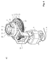
- FIG. 1 shows a perspective view of a first embodiment of a coffee grinder according to the invention.
- the coffee grinder 1 in this case comprises a motor 5, which is controlled / supplied via a cable 6, which can be used for electrical supply and / or optionally also for controlling the motor.
- a housing 7 is present, in which or on which the essential functional elements are arranged.
- the coffee grinder comprises a grinding cone 2 which is arranged within a grinding ring 3.
- the filling region 19 the two elements 2 and 3 are formed conically in opposite directions to form a large gap.
- In this filling gap conveying grooves 29 are also provided both on the grinding cone and on the grinding ring, which are to lead the material to be ground in the actual grinding area.
- the material to be ground may be granular material from the food sector, in particular preferably coffee beans. Likewise, such a mill can also be used for crushing pepper or the like.
- the grinding ring 3 is surrounded by an adjusting ring 4, which has outwardly over ribs 18, via which the adjusting ring 4 can be rotated and thus the grinding gap of the mill can be adjusted. Furthermore, a guide element 8 for arranged the Mahlring.
- the guide element 8 has a resiliently molded onto this latching lug 9, which engages in a row 31 of depressions in the adjusting ring 4 and thus defines 4 defined positions for the rotation of the adjusting ring.
- a gear 10 is arranged.
- This gear 10 is in operative connection with the grinding cone and serves to drive the same.
- the gear 10 is composed of a plurality of components such as an inner hard portion 11, an outer hard portion 13, the teeth, and an intermediate elastic portion 12.
- This elastic portion is made of rubber having a hardness of 20-95 Shore A, preferably 25-90 Shore A, particularly preferably 30-50 Shore A, formed.
- This gear which is rigidly connected via the drive shaft 22 of the grinding cone 2 with the grinding cone 2, is driven by a drive gear 14, which is normally arranged directly on the shaft of the motor 5.
- the tip of this drive gear 14 passes through the housing 7 in an opening 15th
- FIG. 2 shows a top view of a coffee grinder according to FIG. 1.
- the rubber-elastic region 12 between the inner hard region 11 and the outer hard region, the toothing 13 of the toothed wheel 10 is arranged in such a way a permanent relative displacement of the elements 11 and 13 is prevented.
- outwardly directed projections or ribs or webs 17 are arranged on the inner hard area, which protrude into the elastic region 12.
- the teeth 13, inwardly directed projections, ribs or webs 16 are arranged, which also project into the intermediate region 12.
- the projections 16 and 17 are preferably arranged symmetrically offset in the direction of rotation.
- such a coffee grinder comprises considerably fewer individual elements than the prior art, which is one of the great advantages of the proposed design.
- the adjusting ring 4 engages in a rotatable guide 20 (freely rotatable) in the Mahlring 3, and thus ensures that the relative axial position of the elements 3 and 4 is fixed, but not their relative rotational position.
- the connection 20 is preferably designed as a click connection. In the example according to FIG. 3, it is designed such that a groove is present in the grinding ring and a corresponding rib in the adjusting ring, but of course it is also possible to provide a rib on the grinding ring and a groove in the adjusting ring.
- the adjusting ring 4 sits outside on the guide element 8.
- a guide bush 24 is arranged, which is fixed in the guide element 8.
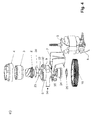
- the grinding ring 3 and the grinding cone 2 are made of a hard material such as steel or ceramic, otherwise these elements would be successively destroyed by the grinding process. It is essential, inter alia, that the actual grinding cone 2 is formed integrally with its drive shaft 22.
- the drive shaft 22 is made of the same material as the grinding cone.
- This drive shaft 22 is mounted in a sliding guide in the guide bush 24. Below the guide bushing 24, the gear 10 is arranged. Between the gear 10 and the guide bush 24 while a spring element 25 is arranged in the form of a corrugated spring.
- the drive shaft 22 via thread grooves 23 and the gear wheel in turn on the inner cylindrical surface of the hub 26 via corresponding guide ribs 28.
- the thread grooves 23 end in the drive shaft 22 in so-called collecting pockets 36. Furthermore, it must be emphasized that the direction of rotation of the mill relative to Screwing the thread grooves 23 in the guide rib 28 is formed such that when the normally prevailing operating direction of rotation of the Mahlkegels the attachment between the gear 10 and drive shaft 22 is tightened.
- the attachment of the grinding cone with the molded-on drive shaft 22 in this construction is extremely simple.
- the grinding cone 2 and its drive shaft can be inserted from above into the guide bushing 24 and from below the gear 10 are placed at intermediate spring element 25 and turned up.
- the thread groove 23 successively screwed into the guide rib 28 until reaching the collecting bag 36 against the spring force of the spring 25, wherein the attachment between the gear 10 and shaft 22 automatically clicks on reaching the collecting bag 36.
- Adjusting ring 4, guide member 8 and the further arranged between grinding cone and guide bushing 24 impeller 30 and the hard elements of the gear 10 are made of plastic, typically of a molded plastic.
- the gear is preferred to use glass fiber reinforced plastic.
- the gear 10 has a construction with an inner hub 26, the outgoing spokes 27 and the already explained inner hard construction 11 (to some extent rim), wherein the elements 26, 27 and 11 are preferably integrally formed.
- the proposed grinder is of a highly modular design and can be adapted to different external conditions.
- the gearwheel 10 it is possible to guide the motor from above into the housing 7, furthermore, it is possible for the gearwheel 10 to also be in the form of a worm wheel or a bevel gearwheel form and, for example, the drive gear 14 tangentially coupled to the gear 10. Since such grinders are installed, for example, in coffee machines as an individual component, this flexibility is of enormous advantage, since it makes it possible to adapt such a grinder, for example, to the predetermined dimensions in an already designed coffee machine.
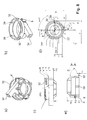
- FIG. 5 shows in detail the grinding cone 2 with the drive shaft 22 formed integrally with the grinding cone.
- the Thread grooves 23 end at their end in a collecting bag 36, respectively.
- FIG. 6 shows the grinding ring with the already explained axial guide recesses 38, which ensure that, when turning on the adjusting ring 4, the grinding ring is displaced exclusively in the axial direction.
- the free rotation of the adjusting ring 4 and the grinding ring 3 can be ensured by the circumferential groove 37. From the figures 6b) - d) possible dimensions for such a grinding ring can be taken.
- Figure 7 shows the gear 10 in different views. From Figure 7a), the very light construction can be seen, which nevertheless has a sufficient stability due to the struts. Possible dimensions (in each case mm) can be taken from FIGS. 7b) and c), and these, as well as the other dimensions mentioned in the context of this disclosure, are of course only to be understood as an example and approximate and simply represent one of the possible realizations. Other dimensions are of course possible depending on load conditions and depending on space. It can be seen in particular from FIGS. 7a) -c) that the guide rib 28 is a somewhat lenticular projection which sweeps over only part of the radial circumference and which is arranged at two opposite positions. Accordingly, the drive shaft 22 has two corresponding thread grooves 23 which cooperate with these guide ribs 28.
- FIG 8 different views of the guide element are shown.
- the guide element 8 has outer guide ribs 32 with a certain pitch.
- the inner axial guide ribs 39 for the corresponding axial guide recesses 38 in the grinding ring 3 can be detected.
- the latching lug 9 which is molded directly on the guide element 8 via a tongue such that the hemisphere at the end is elastically sprung and thus can be completely dispensed with the separate arrangement, for example, a coil spring.
- the guide ribs 32 are formed only in segments, but it can also be a continuous train.
- four axial guide ribs 39 are arranged in the present case, but it is of course also possible to arrange only such a guide rib or two, three or, for example, six such axial guide ribs.
- the arrangement of four such guide ribs is optimal in terms of jamming in many situations.
- FIG. 9 different views of the adjusting ring 4 can be seen.
- the row 31 of depressions on the lower edge can be recognized, in which the latching lug 9 engages in the different rotational positions.
- two such locking lugs 9 are arranged opposite one another, and accordingly the adjusting ring 4 also has two 180 ° segments of parallel to the pitch of the guide groove, respectively. the guide thread 33 extending scenes.
- the guide in the circumferential groove 37 is ideally realized via a nub 40, which allows the adjusting ring to be clicked onto the grinding ring 3 via a click mechanism.
- the Einrastnoppe 40 is easily movable formed, for example, in turn, a tongue. Or simply by the inherent deformability of the material, as is done in the present case (see Figure 9d)).
- FIG. 10 shows different views of the impeller 30, which is arranged between the underside of the grinding cone and the corresponding guide of the guide element 8.
- the impeller 30 is preferably clipped from below onto the grinding cone.
- the impeller 30 has on the outside via wings 41, which serve the ground good from the chamber below the grinder drive out through the opening 34.
- the impeller 30 must rest rotationally fixed on the drive shaft 22, and accordingly, on the inner contour of the impeller 30, limits 42 are provided which engage in corresponding linear grooves of the drive shaft 22 directly below the cone 2.
Landscapes
- Engineering & Computer Science (AREA)
- Mechanical Engineering (AREA)
- Food Science & Technology (AREA)
- Gear Transmission (AREA)
Abstract
Description
Die vorliegende Erfindung betrifft ein verbessertes Mahlwerkzeug zur Zerkleinerung von körnigem Material aus dem Lebensmittelbereich wie insbesondere bevorzugt Getreidekörner, Kaffeebohnen, Pfefferkörner, Salz oder Zucker, mit einem Mahl-Innenkörper respektive Mahlkegel und einem diesen Mahl-Innenkörper unter Bildung eines Mahlspaltes umgebenden feststehenden Mahlring, wobei normalerweise der Mahl-Innenkörper und der Mahlring an ihren gegenüberliegenden Mänteln im oberen Bereich jeweils grössere Fördertaschen bildende Fördernuten und im sich hieran anschliessenden unteren als Mahlkegel ausgestalteten Bereich jeweils Mahlzähne mit geringerer Zahnhöhe aufweisen.The present invention relates to an improved grinding tool for the comminution of granular material from the food sector such as particularly preferred cereal grains, coffee beans, peppercorns, salt or sugar, with a grinding inner body respectively grinding cone and this Mahl-inner body to form a Mahlspaltes surrounding fixed Mahlring, said usually the grinding inner body and the grinding ring at their opposite coats in the upper region each have larger conveyor pockets forming conveying grooves and in the adjoining thereto lower cone designed as Mahlkegel area each having a smaller tooth height.
Zur Lebensmittelzubereitung sind Pfeffer-, Salz- und auch Getreidemühlen der genannten Art bekannt. Problematisch an derartigen Konstruktionen ist in der Regel die Tatsache, dass eine Vielzahl von unterschiedlichen Bauteilen erforderlich ist, um ein gesamtes Mahlwerkzeug zusammen zu bauen. Die Komplexität wird dadurch erhöht, dass einerseits so viele Bauteile wie möglich aus einem billigen Material wie beispielsweise aus gespritztem Kunststoff hergestellt sein sollten, und andererseits gewisse Bauteile, das heisst insbesondere jene, welche den eigentlichen Mahlvorgang durchführen, das heisst der Mahlkegel und der Mahlring, aus einem harten Material wie beispielsweise Metall oder Keramik (oder gegebenenfalls beschichtete Materialien) bestehen sollten. Zudem sollte ein derartiges Mahlwerk eine kompakte Bauweise haben und es sollte in seiner Aussenform möglichst unterschiedlichen Bedingungen angepasst werden können.For food preparation pepper, salt and grain mills of the type mentioned are known. The problem with such constructions is usually the fact that a large number of different components is required in order to assemble an entire grinding tool. The complexity is increased by the fact that on the one hand as many components as possible from a cheap material like For example, should be made of molded plastic, and on the other hand certain components, ie in particular those that perform the actual grinding process, ie the grinding cone and the Mahlring, should consist of a hard material such as metal or ceramic (or optionally coated materials). In addition, such a grinder should have a compact design and it should be able to be adapted in its outer shape as different conditions.
Die
Der Erfindung liegt demnach die Aufgabe zugrunde, ein verbessertes, konstruktiv vereinfachtes, und gleichzeitig sehr zuverlässiges Mahlwerk der eingangs genannten Art zur Verfügung zu stellen.The invention is therefore based on the object to provide an improved, structurally simplified, and at the same time very reliable grinder of the type mentioned.
Konkret handelt es sich um eine Verbesserung eines Mahlwerkzeuges zur Zerkleinerung von körnigem Material aus dem Lebensmittelbereich wie insbesondere bevorzugt Getreidekörner, Kaffeebohnen, Pfefferkörner, Salz oder Zucker, welches ein erstes Mahlelement z.B. in Form eines Mahlkegels und einen dieses erste Mahlelement unter Bildung eines Mahlspaltes umgebenden feststehenden Mahlring (zweites Mahlelement) aufweist (wobei aber auch der Mahlring bewegt und das erste Mahlelement feststehend sein kann).Specifically, it is an improvement of a grinding tool for crushing granular material from the food industry, more preferably grain kernels, coffee beans, peppercorns, salt or sugar containing a first refining element e.g. in the form of a grinding cone and a fixed Mahlring (second grinding element) surrounding this first Mahlelement to form a Mahlspaltes (but also the Mahlring moves and the first Mahlelement can be stationary).
Die erfindungsgemässe Konstruktion ist dabei dadurch gekennzeichnet, dass zwischen Antrieb und dem nicht feststehenden Mahlelement in der Antriebskette wenigstens ein Kupplungselement angeordnet ist, welches wenigstens bereichsweise derart gummielastisch ausgebildet ist, dass der Antrieb an das nicht feststehende Mahlelement elastisch angekoppelt ist.The inventive construction is characterized in that between the drive and the non-fixed grinding element in the drive chain at least one coupling element is arranged, which is at least partially formed so rubbery that the drive is elastically coupled to the non-fixed grinding element.
Normalerweise ist der Antrieb einer derartigen Mühle (der Antrieb ist normalerweise ein Elektromotor) in einer starren Weise über Zahnräder oder ähnliches mit dem eigentlichen Mahlwerk verbunden. Dies bedeutet, dass das bewegliche Element des Mahlwerks in der Regel über ein Getriebe mit Zahnrädern an die Welle des Motors angekoppelt wird. Eine direkte Ankopplung, das heisst die Anordnung des beweglichen Elementes des Mahlwerks auf der Welle des Motors, ist in der Regel nicht möglich, da ansonsten zu leistungsstarke Motoren erforderlich wären. Entsprechend gibt es eine über solche Zahnräder gewährleistete Übersetzung.Normally, the drive of such a mill (the drive is usually an electric motor) in a rigid manner via gears or the like connected to the actual grinder. This means that the movable element of the grinder is usually coupled via a gear with gears to the shaft of the motor. A direct coupling, that is the arrangement of the movable element of the grinder on the shaft of the motor, is not usually possible, otherwise would be required to powerful engines. Accordingly, there is a guaranteed over such gears translation.
Problematisch an einem derartigen Aufbau ist dabei unter anderem, dass durch die immer wieder auftretenden erhöhten Widerstände durch hartes Mahlgut im Mahlspalt beim Mahlvorgang auch laute Geräusche erzeugt werden.The problem with such a structure is, inter alia, that loud noises are generated by the repeatedly occurring increased resistances by hard ground material in the grinding gap during the grinding process.
Weiterhin ist problematisch, dass aufgrund der direkten Rückkopplung der Widerstände im Mahlspalt auf den Motor der Motor auch einer sehr unregelmässigen Belastung ausgesetzt ist und entsprechend der Aufbau fehleranfällig ist. Die ruckartige Belastung des Getriebes ist auch für die einzelnen Zahnräder des Getriebes eine grosse Belastung.Furthermore, it is problematic that due to the direct feedback of the resistors in the grinding gap on the engine, the motor is exposed to a very irregular load and according to the structure is prone to error. The jerky load of the transmission is also a big burden for the individual gears of the transmission.
Der Kern der Erfindung besteht nun unter anderem darin, diese starre Verbindung zwischen der Welle des Motors (oder generell des Antriebs) und dem beweglichen Teile des Mahlwerks durch wenigstens ein elastisches Element gewissermassen aufzuweichen. Dies führt dazu, dass durch die elastische Ankopplung des Antriebs an das nicht feststehende Mahlelement die ruckartigen Belastungen im Mahlspalt aufgefangen werden können. Dies führt zu einer Reduktion der Geräuschbelastung, führt aber auch dazu, dass beim auftreffen auf ein Hindernis im Mahlspalt die notwendige Kraft sukzessive aufgebaut werden kann, indem das elastische Kupplungselement bei im wesentlichen gleich weiterdrehendem Motor die notwendige Kraft aufbaut und beim überschreiten der Grenzkraft unter Entspannung des elastischen Elementes abgeben kann.The essence of the invention is, inter alia, to some extent soften this rigid connection between the shaft of the motor (or generally the drive) and the moving parts of the grinder by at least one elastic element. This results in that the jerky loads in the grinding gap can be absorbed by the elastic coupling of the drive to the non-fixed grinding element. This leads to a reduction of noise pollution, but also leads to the fact that when striking an obstacle in the grinding gap, the necessary force can be built successively by the elastic coupling element builds up the necessary force at substantially the same speed further motor and when exceeding the limit force under relaxation of the elastic element can deliver.
Grundsätzlich kann es sich beim elastischen Kupplungselement beispielsweise um einen elastischen Keilriemen (oder eine analoge Konstruktion) oder um einen elastischen Hebel, um eine elastische Kurbelwelle, einen elastischen Pleuel oder ähnliches handeln. Bevorzugtermassen handelt es sich beim elastischen Kupplungselement aber um ein speziell ausgebildetes Zahnrad. Bevorzugtermassen ist dabei dieses Zahnrad in Bezug auf Torsion (um die Drehachse) elastisch ausgebildet.Basically, the elastic coupling element may be, for example, an elastic V-belt (or an analogous construction) or an elastic lever, an elastic crankshaft, a flexible connecting rod or the like. Preferably, however, the elastic coupling element is a specially designed gear. Preferably, this gear is in relation on torsion (about the axis of rotation) elastic.
Dies ist auf unterschiedliche Weise möglich, beispielsweise ist es möglich, ein Zahnrad mit seiner Nabe auf einer Welle aufzubringen, und zwischen der Nabe und der Welle einen in Bezug auf die Rotation elastischen Gummiring als elastisches Material oder ähnliches aufzubringen. Mit anderen Worten ist es möglich, zwischen Nabe und Welle ein elastisches Material anzuordnen, wobei es sich auch um eine Beschichtung handeln kann.This is possible in different ways, for example, it is possible to apply a gear with its hub on a shaft, and to apply between the hub and the shaft with respect to the rotation elastic rubber ring as an elastic material or the like. In other words, it is possible to arrange an elastic material between hub and shaft, which may also be a coating.
Alternativ, und dies ist die vorliegend bevorzugte Variante, ist es möglich, das Zahnrad als Zwei- oder Mehr-Komponentenbauteil aufzubauen. Dabei kann auf der Innenseite der Nabe direkt ein elastisches Material angeformt sein, und das Zahnrad über dieses elastische Material auf der Welle befestigt sein. Möglich ist es auch, wenigstens im Bereich der Nabe und im Bereich der Zahnung ein hartes, starres Kunststoffmaterial anzuordnen, und im dazwischenliegenden Bereich ein elastisches Material bevorzugtermassen umlaufend vorzusehen. Dieses elastische Material ist dabei derart angeordnet, dass zwischen dem Bereich der Nabe und dem Bereich der Zahnung eine elastische Kopplung besteht. Als hartes Kunststoffmaterial ist in diesem Zusammenhang ein Material zu verstehen, welches zum Beispiel ein E.Modul (Zug) im Bereich von 2000 bis 3500 MPa aufweist. Möglich sind die üblichen KunststoffMaterialien für solche Bauteile, so beispielsweise Polyamid, Polyethylen, Polypropylen, Polycarbonat, ABS Polyoxymethylen/Polyacetal (POM, bevorzugt), Polytetrafluorethylen (PTFE), Polyetheretherketon (PEEK), Polyetherimid (PEI), etc., wobei diese Materialien auch faserverstärkt wie beispielsweise glasfaserverstärkt ausgebildet sein können aber auch Metall wie beispielsweise Aluminium, Stahl, etc..Alternatively, and this is the presently preferred variant, it is possible to construct the gear as a two- or multi-component component. In this case, an elastic material can be formed directly on the inside of the hub, and the gear can be attached via this elastic material on the shaft. It is also possible, at least in the region of the hub and in the area of the teeth, to arrange a hard, rigid plastic material, and to provide an elastic material in the circumferential area, preferably circumferentially. This elastic material is arranged such that there is an elastic coupling between the region of the hub and the region of the toothing. In this context, a hard plastic material is to be understood as meaning a material which, for example, has an E.Module (tension) in the range from 2000 to 3500 MPa. The usual plastic materials are suitable for such components, such as polyamide, polyethylene, polypropylene, polycarbonate, ABS polyoxymethylene / polyacetal (POM, preferred), polytetrafluoroethylene (PTFE), polyetheretherketone (PEEK), polyetherimide (PEI), etc., these materials but also fiber-reinforced such as glass fiber reinforced may be formed but also metal such as aluminum, steel, etc ..
Alternativ ist es auch möglich, das gesamte Zahnrad aus einem derartigen elastischen Material auszubilden.Alternatively, it is also possible to form the entire gear of such an elastic material.
Gemäss einer weiteren bevorzugten Ausführungsform, bei welcher ein derartiges elastisches Material Verwendung findet, handelt es sich beim elastischen Material um ein Material mit einer Härte im Bereich von 35-99 Shore oder 20 - 95 Shore, bevorzugt 25-90 Shore, insbesondere bevorzugt 30-50 Shore (jeweils Shore A, nach DIN 53505, sofern nicht anders angegeben). Als Materialien kommen insbesondere gummielastische Materialien infrage, wie beispielsweise Elastomere, Gummi, oder Kautschuk bevorzugtermassen mit einer derartigen Härte.According to a further preferred embodiment, in which such an elastic material is used, the elastic material is a material having a hardness in the range of 35-99 Shore or 20-95 Shore, preferably 25-90 Shore, particularly preferably 30- 50 Shore (each Shore A, according to DIN 53505, unless otherwise stated). As materials are especially rubber-elastic Materials in question, such as elastomers, rubber or rubber, preferably with such hardness.
Bevorzugtermassen handelt es sich beim elastischen Bereich um einen im wesentlichen hohlzylindrischen (normalerweise kreiszylindrischen) Bereich, welcher auf seiner Aussenseite vom Bereich der Zahnung begrenzt wird und auf seiner Innenseite von der Nabe, wobei gegebenenfalls zwischen der Nabe und dem hohlzylindrischen Bereich harte Speichen und ein innerer harter Bereich angeordnet sein können, so dass der innere harte Bereich auf der Innenseite an den hohlzylindrischen Bereich grenzt. In diesem Zusammenhang sei darauf hingewiesen, dass auch derartige Speichen elastisch ausgebildet werden können. In diesem Fall kann auch härteres Material verwendet werden, sofern die Speichen zur Erreichung der elastischen Wirkung entsprechend dünn ausgebildet sind.Preferably, the elastic region is a substantially hollow cylindrical (usually circular cylindrical) region, which is delimited on its outside by the region of the toothing and on its inside by the hub, optionally between the hub and the hollow cylindrical region hard spokes and an inner Hard area may be arranged so that the inner hard area adjacent to the inside of the hollow cylindrical area. In this context, it should be noted that such spokes can be made elastic. In this case, harder material can be used, provided that the spokes are designed to thin to achieve the elastic effect.
Bevorzugtermassen ist der hohlzylindrische Bereich kraftschlüssig und/oder formschlüssig mit dem Bereich der Zahnung und/oder mit dem inneren harten Bereich und/oder mit der Welle (bei welcher es sich beispielsweise um eine direkt mit einem Mahlkegel verbundene Antriebswelle handeln kann) verbunden respektive mit diesen Bereichen verklebt. Zudem ist es möglich, dass auf der axial inneren Seite des Bereiches der Zahnung und/oder auf der axial äusseren Seite des inneren harten Bereiches in den elastischen Bereich hineinragende Vorsprünge und/oder Stege und/oder Rippen angeordnet sind. Auch die umgekehrte Situation ist denkbar, das heisst dass der elastische Bereich über Vorsprünge und/oder Stege und/oder Rippen verfügt, welche in entsprechender Ausnehmungen im inneren harten Bereich und/oder im Bereich der Zahnung hineinragen.Preferably, the hollow cylindrical region is non-positively and / or positively connected to the region of the toothing and / or to the inner hard region and / or to the shaft (which may, for example, be a drive shaft connected directly to a milling cone) respectively with these Glued areas. In addition, it is possible for projections and / or webs and / or ribs to project into the elastic region on the axially inner side of the region of the toothing and / or on the axially outer side of the inner hard region. The opposite situation is also conceivable, that is to say that the elastic region has projections and / or webs and / or ribs which protrude into corresponding recesses in the inner hard region and / or in the region of the toothing.
Gemäss einer entsprechend weiterhin bevorzugten Ausführungsform der Erfindung verfügen die Vorsprünge und/oder Stege und/oder Rippen über eine radiale Höhe, welche geringer ist als die radiale Breite des elastischen Bereiches, wobei insbesondere bevorzugt die radiale Höhe im Bereich von 30-70%, insbesondere bevorzugt im Bereich von 50% der radialen Breite des elastischen Bereiches ausgebildet ist. Eine ideale elastische Kopplung kann erreicht werden, wenn beispielsweise die Vorsprünge und/oder Stege und/oder Rippen am Bereich der Zahnung (das heisst gewissermassen radial nach innen gerichtet) und die Vorsprünge und/oder Stege und/oder Rippen am inneren harten Bereich (das heisst gewissermassen radial nach aussen gerichtet) umlaufinässig versetzt angeordnet sind, insbesondere bevorzugt symmetrisch. Es können dabei beispielsweise jeweils 3-20, insbesondere bevorzugt 5-12 derartige Vorsprünge angeordnet sein.According to a further preferred embodiment of the invention, the projections and / or webs and / or ribs have a radial height which is less than the radial width of the elastic region, wherein particularly preferably the radial height in the range of 30-70%, in particular is preferably formed in the range of 50% of the radial width of the elastic region. An ideal elastic coupling can be achieved if, for example, the projections and / or webs and / or ribs on the region of the toothing (that is, to some extent directed radially inward) and the projections and / or webs and / or ribs on the inner hard area (that is, in a sense directed radially outward to the outside) are arranged circumferentially offset, in particular preferably symmetrical. For example, in each case 3-20, in particular preferably 5-12, such projections may be arranged.
Die Bauweise des Zahnrades kann unterschiedlich sein, so kann es sich beispielsweise beim Zahnrad um ein Stirnzahnrad, um ein Schneckenzahnrad oder um ein Kegelzahnrad handeln.The construction of the gear can be different, so it can be, for example, the gear to a spur gear, a worm gear or a bevel gear.
Gemäss einer weiter bevorzugten Ausführungsform der Erfindung handelt es sich beim ersten Mahlelement um einen Mahlkegel, wobei der Mahlring feststehend ausgebildet ist, und wobei der Mahlkegel über eine koaxiale, wenigstens im Lagerbereich zylindrische, in einem Lager drehbar gelagerte Antriebswelle mittelbar mit dem Antrieb verbunden ist, und wobei bevorzugtermassen die Antriebswelle und der Mahlkegel einstückig ausgebildet sind.According to a further preferred embodiment of the invention, the first grinding element is a grinding cone, wherein the grinding ring is stationary, and wherein the grinding cone is indirectly connected to the drive via a coaxial, at least in the bearing area cylindrical, rotatably mounted in a bearing drive shaft and wherein preferably the drive shaft and the grinding cone are integrally formed.
Konstruktiv und hinsichtlich der Montage ist eine solche Bauweise besonders vorteilhaft, wenn die Antriebswelle über eine selbsteinrastende Rastverbindung mit einem (bevorzugtermassen das elastische Kupplungselement bildenden) Zahnrad verbunden ist.Structurally and in terms of assembly, such a design is particularly advantageous when the drive shaft is connected via a self-locking detent connection with a (preferably the elastic coupling element forming) gear.
Bevorzugtermassen ist in diesem Zusammenhang die Antriebswelle mit einem Aussengewinde oder wenigstens einer Gewinderille versehen, und dieses Aussengewinde respektive die wenigstens eine Gewinderille greift direkt in ein in der zylindrischen Innenfläche der Nabe eines Zahnrades vorgesehenes Innengewinde respektive Führungsrippe ein und/oder die Antriebswelle weist wenigstens eine, bevorzugt zwei Gewinderillen auf. Das Zahnrad weist wenigstens eine, bevorzugt zwei Führungsrippen auf, welche bevorzugtermassen nur über einen Winkelbereich von 5-30° ausgebildet sind, wobei insbesondere bevorzugt das Aussengewinde respektive die Gewinderillen eine Auffangtasche aufweisen, in welche die Verbindung zwischen Antriebswelle und Zahnrad selbsteinrastend beim erreichen des Anschlages einrastet.Preferably, in this context, the drive shaft is provided with an external thread or at least one thread groove, and this external thread or the at least one thread groove engages directly into an inner thread or guide rib provided in the cylindrical inner surface of the hub of a gearwheel and / or the drive shaft has at least one, preferably two thread grooves on. The toothed wheel has at least one, preferably two guide ribs, which are preferably formed only over an angular range of 5-30 °, wherein in particular preferably the external thread respectively the thread grooves have a collecting pocket, in which the connection between the drive shaft and gear selbsteinrastend when reaching the stop locks.
Bei einer derartigen Bauweise kann auch zwischen einem bevorzugtermassen als Gleitlager ausgebildeten Lager und dem Zahnrad ein Federelement angeordnet werden, welches eine Rückstellkraft in axialer Richtung zur Unterstützung der Selbsteinrastung gewährleistet, wobei es sich bevorzugtermassen bei diesem Federelement um eine Wellfeder handelt. Dabei sind das Lager und/oder das Zahnrad beispielsweise wenigstens teilweise aus Kunststoff gefertigt, und insbesondere bevorzugt hergestellt in einem Spritzgussverfahren.In such a construction can also be between a preferred as Plain bearing trained bearing and the gear a spring element can be arranged, which ensures a restoring force in the axial direction to support the Selbsteinrastung, which is preferably in this spring element is a corrugated spring. The bearing and / or the gear are, for example, at least partially made of plastic, and particularly preferably produced in an injection molding process.
Bevorzugtermassen sind der Mahlkegel und die daran angeordnete Antriebswelle und/oder der Mahlring aus Metall, insbesondere bevorzugt aus Stahl, aus einem mit einem gehärteten Material beschichteten Körper, oder aus Keramik gefertigt.Preferably, the grinding cone and the drive shaft arranged thereon and / or the grinding ring are made of metal, particularly preferably of steel, of a body coated with a hardened material, or of ceramic.
Wie bereits erläutert, kann es sich beim Antrieb um einen manuellen Antrieb oder insbesondere bevorzugt um einen elektromotorischen Antrieb handeln, wobei insbesondere bevorzugt das Zahnrad angetrieben wird über ein Antriebszahnrad, welches direkt auf der Welle des Elektromotors angeordnet ist.As already explained, the drive may be a manual drive or, more preferably, an electromotive drive, wherein the gear is particularly preferably driven via a drive gear, which is arranged directly on the shaft of the electric motor.
Weitere bevorzugte Ausführungsformen der Erfindung sind in den abhängigen Ansprüchen beschrieben.Further preferred embodiments of the invention are described in the dependent claims.
Folgende Elemente sind zusammenfassend entweder in Kombination oder jeweils einzeln betrachtet für sich genommen erfindungsgemässe Konstruktionen, welche auch unabhängig von den oben genannten Merkmalen Neuheit und erfinderischen Charakter aufweisen:
- Verbindung von Mahlkegel und Abtriebswelle zu einer einstückigen Einheit verringert den Montageaufwand u. reduziert die Summentoleranzen.
- Verbindung von Abtriebswelle und -Zahnrad durch einen angespritzten EinrastVerschluss. Dabei wird das Antriebszahnrad über ein Federelement auf den Antriebsbolzen vorgespannt eingerastet.
- Geräuschdämpfung beim Abrollen des Antriebszahnrades auf dem Abtriebszahnrad durch einen 2-Komponenten-Aufbau des Abtriebzahnrades: Das Zahnrad wird durch eine Dämpfungsschicht aus Gummi unter dem Zahnkranz gegen Schwingungs- und Körperschallübertragungen gedämpft. Weiters verleiht dieser Aufbau eine Elastizität in radialer Richtung am Zahnkranz und dämpft dadurch die Krafteinleitung im Falle des Blockierens.
- Verstellrasterung über angespritzte Halbkugeln auf einem Filmscharnier des Grundgehäuses, welche im Verstellring einrasten (vergleiche die weiter unten im Detail diskutierte Rastnase 9 zusammen mit dem
Verstellring 4 und den darin angeordneten Vertiefungen 31). Die Rasterung (Vertiefungen 31) am Verstellring ist ebenfalls mitgespritzt. - Für eine weiter abgesicherte Variante ist der Einbau einer Rutschkuppelung direkt zwischen Abtriebswelle und Nabe des Abtriebszahnrades vorgesehen.
- Modulbauweise: Durch die Modulbauweise ist es möglich, den Antriebsmotor jeweils zum Beispiel um 90° Grad um die Längsachse zu versetzen, wodurch besser auf die Platzverhältnis in der jeweiligen Kaffeemaschine eingegangen werden kann. Die starke Reduktion der Anzahl der einzelnen Bauteile sowie die modulare Bauweise ist ein grosser Vorteil insbesondere bei derartigen Mahlwerken, welche in grössere Maschinen eingebaut werden sollen, da auf unterschiedlichste Platzverhältnisse angepasst werden kann.
- Verstellmechanismus: Der Verstellmechanismus des Mahlwerks ist durch Integration der Längsführungen (vergleiche die weiter unten diskutierten axialen Führungen 38) in den Mahlring bzw. in das Grundgehäuse (vergleiche das weiter unten diskutierte Führungselement 8)
mit lediglich 2 Teilen machbar. Dies ist möglich durch die Integration von Funktionen des Verstellmechanismus' in den Mahlring.
- Connection of grinding cone and output shaft to a one-piece unit reduces the assembly costs u. reduces the sum tolerances.
- Connection of output shaft and gear through a molded snap-in lock. The drive gear is locked biased by a spring element on the drive pin.
- Noise damping when rolling the drive gear on the output gear through a 2-component structure of the output gear: The gear is damped by a rubber damping layer under the ring gear against vibration and structure-borne sound transmissions. Furthermore, this structure gives elasticity in the radial direction on Sprocket and thereby dampens the introduction of force in the case of blocking.
- Verstellrasterung about molded hemispheres on a film hinge of the base housing, which engage in the adjusting ring (see the detail discussed below
detent 9 together with the adjustingring 4 and therecesses 31 disposed therein). The screening (recesses 31) on the adjusting ring is also injected. - For a more secure version of the installation of a slip coupling is provided directly between the output shaft and hub of the output gear.
- Modular design: Due to the modular design, it is possible to offset the drive motor, for example, by 90 ° degrees around the longitudinal axis, so that the space ratio in the respective coffee machine can be better addressed. The strong reduction in the number of individual components and the modular design is a great advantage especially in such grinders, which are to be installed in larger machines, as can be adapted to different space conditions.
- Adjusting mechanism: The adjusting mechanism of the grinder is feasible by integrating the longitudinal guides (compare the axial guides 38 discussed below) into the grinding ring or into the basic housing (compare the
guide element 8 discussed below) with only two parts. This is possible by the integration of functions of the adjusting mechanism 'in the Mahlring.
Die Erfindung soll nachfolgend anhand von Ausführungsbeispielen im Zusammenhang mit den Zeichnungen näher erläutert werden. Es zeigen:
- Fig. 1
- Eine perspektivische Ansicht einer Kaffeemühle gemäss einem ersten Ausführungsbeispiel;
- Fig. 2
- Eine Ansicht auf die
Kaffeemühle gemäss Figur 1 von oben; - Fig. 3
- Einen Schnitt durch die
Kaffeemühle gemäss Figur 1 entlang der Schnittlinie A-A inFigur 2; - Fig. 4
- Eine Kaffeemühle gemäss einem weiteren Ausführungsbeispiel, wobei a) eine perspektivische Ansicht von schräg oben darstellt; b) eine perspektivische Ansicht von schräg unten darstellt; c) eine Ansicht von oben darstellt; d) einen axialen Schnitt entlang der Schnittlinie A-A in Figur 4c) darstellt; e) eine Explosionsdarstellung der einzelnen Elemente dieses Ausführungsbeispiels darstellt;
- Fig. 5
- Verschiedene Ansichten des einstückig ausgebildeten Mahlkegels mit Antriebswelle, wobei a) eine perspektivische Ansicht darstellt; b) eine Ansicht von oben darstellt; c) eine Ansicht von der Seite darstellt;
- Fig. 6
- Unterschiedliche Ansichten des Mahlringes darstellt, wobei in a) eine perspektivische Ansicht dargestellt ist, in b) eine Ansicht von der Seite; in c) ein axialer Schnitt dargestellt ist; in d) ein Detail gemäss Ausschnitt D in b) dargestellt ist;
- Fig. 7
- Unterschiedliche Ansichten des Zahnrades, wobei in a) eine perspektivische Ansicht dargestellt ist, in b) eine Aufsicht dargestellt ist; und in c) ein axialer Schnitt entlang der Schnittlinie A-A in b) dargestellt ist;
- Fig.
- 8 Unterschiedliche Ansichten des Führungselements, wobei in a) eine perspektivische Ansicht von schräg unten dargestellt ist, in b) eine perspektivische Ansicht von schräg oben dargestellt ist; in c) eine seitliche Ansicht dargestellt ist; in d) eine Aufsicht von oben dargestellt ist; in e) ein axialer Schnitt entlang der Schnittlinie A-A in d) dargestellt ist;
- Fig. 9
- Unterschiedliche Ansichten des Verstellringes, wobei in a) eine perspektivische Ansicht von schräg unten dargestellt ist, in b) eine perspektivische Ansicht von schräg oben dargestellt ist; in c) eine seitliche Ansicht dargestellt ist; in d) ein axialer Schnitt entlang der Linie A-A in f) dargestellt ist; in e) eine Ansicht von unten dargestellt ist; in f) eine Ansicht von oben dargestellt ist; in g) der Schnitt entlang der Linie B-B in e) dargestellt ist, und in h) der Ausschnitt C aus Figur 9 g) dargestellt ist; und
- Fig. 10
- Unterschiedliche Ansichten des Flügelrades, wobei in a) eine perspektivische Ansicht dargestellt ist, in b) ein axialer Schnitt entlang der Linie A-A in c) dargestellt ist und in c) eine Aufsicht dargestellt ist.
- Fig. 1
- A perspective view of a coffee grinder according to a first embodiment;
- Fig. 2
- A view of the coffee grinder according to Figure 1 from above;
- Fig. 3
- A section through the coffee grinder according to Figure 1 along the section line AA in Figure 2;
- Fig. 4
- A coffee grinder according to another embodiment, wherein a) is a perspective view obliquely from above; b) shows a perspective view obliquely from below; c) represents a view from above; d) shows an axial section along the section line AA in Figure 4c); e) represents an exploded view of the individual elements of this embodiment;
- Fig. 5
- Various views of the integrally formed Mahlkegels with drive shaft, wherein a) represents a perspective view; b) represents a view from above; c) represents a view from the side;
- Fig. 6
- Different views of the Mahlringes, wherein in a) a perspective view is shown in b) a view from the side; in c) an axial section is shown; in d) a detail according to detail D in b) is shown;
- Fig. 7
- Different views of the gear, wherein in a) a perspective view is shown, b) is shown in a plan view; and in c) an axial section along the section line AA in b) is shown;
- FIG.
- 8 different views of the guide element, wherein in a) a perspective view is shown obliquely from below, in b) is a perspective view obliquely from above; in c) a side view is shown; in d) a top view is shown; in e) an axial section along the section line AA in d) is shown;
- Fig. 9
- Different views of the adjusting ring, wherein in a) a perspective view is shown obliquely from below, in b) is a perspective view shown obliquely from above; in c) a side view is shown; in d) an axial section along the line AA in f) is shown; in e) a view from below is shown; in f) a view from above is shown; in g) the section along the line BB in e) is shown, and in h) the section C from FIG. 9 g) is shown; and
- Fig. 10
- Different views of the impeller, wherein in a) a perspective view is shown in b) an axial section along the line AA in c) is shown and in c) is shown a plan view.
In der Folge soll die Erfindung anhand von mehreren Beispielen erläutert werden. Die Erläuterung dieser Beispiele und deren Funktionsweise dient dabei zur Illustration der technischen Durchführbarkeit der Erfindung sowie unterschiedlicher Bauweisen. Die Ausführungsbeispiele sollen aber nicht zur Einschränkung des Schutzgegenstandes, wie er in den angehängten Patentansprüchen definiert ist, ausgelegt werden.In the following, the invention will be explained with reference to several examples. The explanation of these examples and their operation serves to illustrate the technical feasibility of the invention and different designs. However, the embodiments should not be construed as limiting the subject matter of the invention as defined in the appended claims.
In Figur 1 ist eine perspektivische Ansicht eines erstes Ausführungsbeispieles einer Kaffeemühle nach der Erfindung dargestellt. Die Kaffeemühle 1 umfasst dabei einen Motor 5, welcher über ein Kabel 6, welches zur elektrischen Versorgung und/oder gegebenenfalls auch zur Steuerung des Motors verwendet werden kann, angesteuert/versorgt wird. Weiterhin ist ein Gehäuse 7 vorhanden, in respektive an welchem die wesentlichen funktionellen Elemente angeordnet sind. Die Kaffeemühle umfasst einen Mahlkegel 2, welcher innerhalb eines Mahlringes 3 angeordnet ist. In einem oberen Bereich, dem Füllbereich 19, sind die beiden Elemente 2 und 3 gegenläufig konisch unter Ausbildung eines grossen Spaltes ausgebildet. In diesem Füllspalt sind zudem sowohl am Mahlkegel wie auch am Mahlring Fördernuten 29 vorgesehen, welche das Mahlgut in den eigentlichen Mahlbereich führen sollen. Beim Mahlgut kann es sich um körniges Material aus dem Nahrungsmittelbereich handeln, insbesondere bevorzugt handelt es sich um Kaffeebohnen. Gleichermassen kann eine derartige Mühle aber auch zur Zerkleinerung von Pfeffer oder ähnlichem verwendet werden.FIG. 1 shows a perspective view of a first embodiment of a coffee grinder according to the invention. The
Der Mahlring 3 ist umgeben von einem Verstellring 4, welcher nach Aussen über Rippen 18 verfügt, über welche der Verstellring 4 gedreht werden kann und damit der Mahlspalt der Mühle eingestellt werden kann. Weiterhin ist ein Führungselement 8 für den Mahlring angeordnet. Das Führungselement 8 verfügt über eine an diesem elastisch angespritzten Rastnase 9, welche in eine Reihe 31 von Vertiefungen im Verstellring 4 eingreift und somit für die Rotation des Verstellringes 4 definierte Positionen vorgibt.The grinding
Am Führungselement 8 ist normalerweise auch eine Austrittsöffnung 34 für das gemahlene Mahlgut angeformt.On the
Unterhalb dieser Elemente ist ein Zahnrad 10 angeordnet. Dieses Zahnrad 10 ist in Wirkverbindung mit dem Mahlkegel und dient zum Antrieb desselben. Das Zahnrad 10 ist aus mehreren Komponenten aufgebaut, so aus einem inneren harten Bereich 11, einem äusseren harten Bereich 13, der Zahnung, und einem dazwischenliegenden elastischen Bereich 12. Dieser elastische Bereich ist aus Gummi mit einer Härte von 20-95 Shore A, bevorzugt 25-90 Shore A, insbesondere bevorzugt 30-50 Shore A, ausgebildet. Dieses Zahnrad, welches starr über die Antriebswelle 22 des Mahlkegels 2 mit dem Mahlkegel 2 verbunden ist, wird angetrieben von einem Antriebszahnrad 14, welches normalerweise direkt auf der Welle des Motors 5 angeordnet ist. Im vorliegenden Fall durchtritt die Spitze dieses Antriebszahnrades 14 das Gehäuse 7 in einer Öffnung 15.Below these elements, a
Figur 2 zeigt eine Ansicht von oben auf eine Kaffeemühle gemäss Figur 1. Hierbei kann unter anderem erkannt werden, dass der gummielastische Bereich 12 zwischen dem inneren harten Bereich 11 und dem äusseren harten Bereich, der Zahnung 13 des Zahnrades 10, derart angeordnet ist, dass eine bleibende relative Verschiebung der Elemente 11 und 13 verhindert wird. Zu diesem Zweck sind am inneren harten Bereich nach aussen gerichtete Vorsprünge oder Rippen oder Stege 17 angeordnet, welche in den elastischen Bereich 12 hineinragen. Gleichermassen sind gewissermassen entgegengesetzt am äusseren harten Bereich, der Zahnung 13, nach innen gerichtete Vorsprünge, Rippen oder Stege 16 angeordnet, welche ebenfalls in den Zwischenbereich 12 hineinragen. Die Vorsprünge 16 und 17 sind dabei bevorzugtermnassen symmetrisch versetzt in Rotationsrichtung angeordnet. Durch diese Verzahnung der Elemente 16 und 17 in den elastischen Bereich 12 wird sichergestellt, dass der Bereich 12 nur in elastischer Hinsicht wirkt und kein Rutschen zwischen den Elementen 11 und 13 möglich ist.FIG. 2 shows a top view of a coffee grinder according to FIG. 1. It can be seen, inter alia, that the rubber-
Wie aus der Schnittdarstellung gemäss Figur 3 erkannt werden kann, umfasst eine derartige Kaffeemühle im Vergleich zum Stand der Technik wesentlich weniger einzelne Elemente, was einer der grossen Vorteile der vorgeschlagenen Bauweise ist.As can be seen from the sectional view according to FIG. 3, such a coffee grinder comprises considerably fewer individual elements than the prior art, which is one of the great advantages of the proposed design.
Der Verstellring 4 greift in einer drehbaren Führung 20 (frei drehbar) in den Mahlring 3 ein, und stellt somit sicher, dass die relative axiale Position der Elemente 3 und 4 fixiert ist, nicht aber deren relative Rotationsposition. Die Verbindung 20 ist bevorzugtermassen als Klick-Verbindung ausgestaltet. Im Beispiel gemäss Figur 3 ist sie so ausgestaltet, dass im Mahlring eine Nut vorhanden ist und im Verstellring eine entsprechende Rippe, selbstverständlich ist es aber auch möglich, am Mahlring eine Rippe vorzusehen und im Verstellring eine Nut.The adjusting
Der Verstellring 4 sitzt aussen auf dem Führungselement 8 auf. Als eigentliches Lager für die Antriebswelle respektive Spindel 22 des Mahlkegels 2 ist eine Führungsbuchse 24 angeordnet, welche im Führungselement 8 fixiert ist.The adjusting
Wie sich aus der eigentlichen Aufgabe der Kaffeemühle ergibt, ist der Mahlring 3 sowie der Mahlkegel 2 aus einem harten Material wie bspw. Stahl oder auch Keramik gefertigt, da anderenfalls diese Elemente durch den Mahlvorgang sukzessive zerstört würden. Wesentlich ist nun unter anderem, dass der eigentliche Mahlkegel 2 einstückig mit seiner Antriebswelle 22 ausgebildet ist. Mit anderen Worten ist die Antriebswelle 22 aus dem gleichen Material wie der Mahlkegel. Diese Antriebswelle 22 ist in einer Gleitführung in der Führungsbuchse 24 gelagert. Unterhalb der Führungsbuchse 24 ist das Zahnrad 10 angeordnet. Zwischen dem Zahnrad 10 und der Führungsbuchse 24 ist dabei ein Federelement 25 in Form einer Wellfeder angeordnet. Zudem verfügt die Antriebswelle 22 über Gewinderillen 23 und das Zahnrad seinerseits auf der innenliegenden Zylinderfläche der Nabe 26 über entsprechende Führungsrippen 28. Weiterhin enden die Gewinderillen 23 in der Antriebswelle 22 in sogenannten Auffangtaschen 36. Weiterhin muss herausgestrichen werden, dass die Drehrichtung der Mühle relativ zur Einschraubrichtung der Gewinderillen 23 in die Führungsrippe 28 derart ausgebildet ist, dass bei der im Betrieb normalerweise herrschenden Rotationsrichtung des Mahlkegels die Befestigung zwischen Zahnrad 10 und Antriebswelle 22 festgezogen wird.As can be seen from the actual task of the coffee grinder, the grinding
Überhaupt ist die Befestigung des Mahlkegels mit der daran angeformten Antriebswelle 22 in dieser Konstruktion äusserst einfach. So kann nämlich der Mahlkegel 2 respektive seine Antriebswelle von oben in die Führungsbuchse 24 eingeschoben werden und von unten das Zahnrad 10 bei dazwischenliegendem Federelement 25 aufgesetzt und aufgedreht werden. Dabei schraubt sich die Gewinderille 23 sukzessive in die Führungsrippe 28 ein bis zum Erreichen der Auffangtasche 36 gegen die Federkraft der Feder 25, wobei beim Erreichen der Auffangtasche 36 die Befestigung zwischen Zahnrad 10 und Welle 22 automatisch verklickt.In general, the attachment of the grinding cone with the molded-on
Verstellring 4, Führungselement 8 sowie das weiterhin zwischen Mahlkegel und Führungsbuchse 24 angeordnete Flügelrad 30 und auch die harten Elemente des Zahnrades 10 sind aus Kunststoff gefertigt, typischerweise aus einem gespritzten Kunststoff. Insbesondere beim Zahnrad ist dabei bevorzugt, glasfaserverstärkten Kunststoff zu verwenden. Das Zahnrad 10 verfügt dabei über eine Konstruktion mit einer innenliegenden Nabe 26, davon abgehenden Speichen 27 und der bereits erläuterten inneren harten Konstruktion 11 (gewissermassen Felge), wobei die Elemente 26, 27 und 11 bevorzugtermassen einstückig ausgeformt sind.Adjusting
Wie aus der Zusammenschau der Figuren 1 - 3 erkannt werden kann, ergibt sich somit aufgrund der einstückigen Ausbildung von Mahlkegel 2 und Antriebswelle 22 eine in Bezug auf die Herstellung aber auch in Bezug auf die Montage sehr einfache Bauweise, welche zu einer Reduktion der Anzahl der notwendigen Teile führt. Zudem ergibt sich durch den gummielastischen Bereich 12 eine teilweise Entkopplung des eigentlichen Mahlwerkes vom Motor. Es handelt sich dabei aufgrund des elastischen Bereiches 12 um eine gewissermassen elastische Entkopplung, was einerseits zu einer erhöhten Leichtgängigkeit beim Mahlvorgang führt, und andererseits eine erhebliche Geräuschdämpfung beim Mahlvorgang nach sich zieht.As can be seen from the synopsis of Figures 1 - 3, thus resulting due to the integral formation of grinding
Weiterhin ergibt sich aus der Zusammenschau der Figuren 1 - 3 (sowie auch aufgrund des anfolgend gezeigten Beispieles), dass das vorgeschlagene Mahlwerk stark modular aufgebaut ist und unterschiedlichen äusseren Rahmenbedingungen angepasst werden kann. So ist es bspw. möglich, den Motor auch von oben in das Gehäuse 7 zu führen, weiterhin ist es möglich, das Zahnrad 10 auch als Schneckenrad oder als Kegelzahnrad auszubilden und bspw. das Antriebszahnrad 14 tangential an das Zahnrad 10 anzukoppeln. Da derartige Mahlwerke bspw. in Kaffeemaschinen als individuelles Bauteil eingebaut werden, ist diese Flexibilität von enormem Vorteil, da sie ermöglicht, ein derartiges Mahlwerk bspw. den vorgegebenen Dimensionen in einer bereits gestalteten Kaffeemaschine anzupassen.Furthermore, it follows from the synopsis of FIGS. 1-3 (as well as on the basis of the example shown below) that the proposed grinder is of a highly modular design and can be adapted to different external conditions. For example, it is possible to guide the motor from above into the
Die nun anfolgenden Figuren zeigen ein weiteres Ausführungsbeispiel einer Kaffeemühle nach der Erfindung. In Figur 4a) und b) sind perspektivische Ansichten dieses weiteren Ausführungsbeispieles dargestellt, wobei in a) eine Ansicht von schräg oben dargestellt ist und in b) eine Ansicht von schräg unten. Im Wesentlichen ist die Bauweise analog zur Bauweise gemäss den Figuren 1-3, das Gehäuseelement 7 ist hier aber im Wesentlichen nur als stark reduziertes Tragelement ausgebildet. Insbesondere aus Figur 4 kann dabei auch die sehr schlanke axiale Bauweise erkannt werden. Aus Figur 4c) kann erkannt werden, dass auch in radialer Ausdehnung das vorgeschlagene Mahlwerk über sehr geringe Dimensionen verfügt.The following figures show a further embodiment of a coffee grinder according to the invention. In Figure 4a) and b) perspective views of this further embodiment are shown, wherein in a) a view is shown obliquely from above and in b) a view obliquely from below. In essence, the construction is analogous to the construction according to FIGS. 1-3, but the
Unter anderem aus Figur 4d) kann gesehen werden, dass der Verstellring 4 mit Führungsnuten 33 resp. einem eigentlichen Führungsgewinde ausgestattet ist, welches mit aussenliegenden Führungsrippen 32 am Führungselement 8 kooperiert. Wird am Verstellring 4 gedreht, so verschiebt sich, aufgrund der freien Drehbarkeit zwischen Mahlring 3 und Verstellring 4 und aufgrund der weiterhin im Mahlring 3 vorgesehenen Führungsnuten 38 und der im Führungselement 8 angeordneten Führungsrippen 39 der Mahlring 3 aufgrund der Steigung des Gewindes 32/33 ausschliesslich in axialer Richtung, und so kann die Beabstandung des eigentlichen Mahlspaltes eingestellt werden. Dies ist die sogenannte Mahlgradverstellung (Einstellung der Feinheit des gemahlenen Gutes).Among other things, from Figure 4d) can be seen that the adjusting
Aus Figur 4e) kann die dramatische Reduktion der Anzahl der Bauteile erkannt werden. Im Wesentlichen werden nur noch ca. 14 Bauteile benötigt, und es sind aufgrund der Vielzahl von verwendeten Klick-Mechanismen nur 4 Schrauben 35 erforderlich, was angesichts der hohen axialen Belastung beim Mahlvorgang sehr überraschend ist.From Figure 4e), the dramatic reduction in the number of components can be detected. In essence, only about 14 components are needed, and there are only 4
Figur 5 zeigt im Detail den Mahlkegel 2 mit der einstückig mit dem Mahlkegel ausgebildeten Antriebswelle 22. Insbesondere kann erkannt werden, dass die Gewinderillen 23 an ihrem Ende jeweils in einer Auffangtasche 36 enden. Durch die Kooperation mit den bereits erwähnten Führungsrippen 28 an der Nabe 26 des Zahnrades 10 kann so eine definitive Anschlags- und Einrastposition für die relative Fixierung von Mahlkegel resp. Antriebswelle 22 am Zahnrad 10 gewährleistet werden. Weiterhin können aus den Figuren 5b) und c) typische und mögliche Bemassungen eines derartigen Mahlkegels entnommen werden.FIG. 5 shows in detail the grinding
Figur 6 zeigt den Mahlring mit den bereits erläuterten axialen Führungsausnehmungen 38, welche sicherstellen, dass bei einem Drehen am Verstellring 4 der Mahlring ausschliesslich in axialer Richtung verschoben wird. Zudem kann erkannt werden, dass durch die umlaufende Nut 37 die freie Drehbarkeit von Verstellring 4 und Mahlring 3 gewährleistet werden kann. Aus den Figuren 6b) - d) können mögliche Bemassungen für einen derartigen Mahlring entnommen werden.FIG. 6 shows the grinding ring with the already explained axial guide recesses 38, which ensure that, when turning on the adjusting
Figur 7 zeigt das Zahnrad 10 in unterschiedlichen Ansichten. Aus Figur 7a) kann die sehr leichte Bauweise gesehen werden, welche aufgrund der Verstrebungen trotzdem eine genügende Stabilität aufweist. Aus den Figuren 7b) und c) können mögliche Bemassungen (jeweils Millimeter) entnommen werden, wobei diese, wie auch die anderen im Rahmen dieser Offenbarung genannten Bemassungen, selbstverständlich nur beispielhaft und näherungsweise zu verstehen sind und einfach eine der möglichen Realisierungen darstellen. Andere Bemassungen sind je nach Belastungsverhältnissen und je nach Platzverhältnissen selbstverständlich möglich. Aus den Figuren 7a) - c) kann insbesondere erkannt werden, dass es sich bei der Führungsrippe 28 um eine gewissermassen linsenförmige nur einen Teil des radialen Umfangs überstreichenden Vorsprung handelt, welcher an zwei gegenüberliegenden Positionen angeordnet ist. Entsprechend verfügt auch die Antriebswelle 22 über zwei korrespondierende Gewinderillen 23, welche mit diesen Führungsrippen 28 kooperieren.Figure 7 shows the
In Figur 8 sind unterschiedliche Ansichten des Führungselementes dargestellt. Insbesondere kann erkannt werden, dass das Führungselement 8 über aussenliegende Führungsrippen 32 verfügt mit einer gewissen Steigung. Weiterhin können die innenliegenden axialen Führungsrippen 39 für die korrespondierenden axialen Führungsausnehmungen 38 im Mahlring 3 erkannt werden.In Figure 8 different views of the guide element are shown. In particular, it can be seen that the
Insbesondere herauszustreichen ist dabei vor allem auch die Rastnase 9, welche direkt am Führungselement 8 über eine Zunge derart angespritzt ist, dass die am Ende liegende Halbkugel elastisch gefedert ist und somit auf die separate Anordnung bspw. einer Spiralfeder vollständig verzichtet werden kann. Wie bereits erläutert, greift die Rastnase 9 in entsprechende Vertiefungen 31 im Verstellring 4 ein und legt so unterschiedliche Rotationsposition des Verstellrings eindeutig fest. Im vorliegenden Fall sind die Führungsrippen 32 nur segmentweise ausgebildet, es kann sich aber auch um einen durchlaufenden Zug handeln. Weiterhin sind im vorliegenden Fall vier axiale Führungsrippen 39 angeordnet, es ist aber selbstverständlich auch möglich, nur eine derartige Führungsrippe oder zwei, drei oder bspw. auch sechs derartige axiale Führungsrippen anzuordnen. Die Anordnung von vier derartigen Führungsrippen ist aber hinsichtlich der Verklemmung in vielen Situationen optimal.In particular, it is especially the latching
In Figur 9 sind unterschiedliche Ansichten des Verstellringes 4 zu erkennen. Insbesondere kann dabei die Reihe 31 von Vertiefungen an der Unterkante erkannt werden, in welche die Rastnase 9 bei den unterschiedlichen Rotationspositionen eingreift. Wie auch aus Figur 8d) erkannt werden kann, sind zwei derartige Rastnasen 9 gegenüberliegend angeordnet, und entsprechend verfügt der Verstellring 4 auch über zwei 180° Segmente von parallel zur Steigung der Führungsnut resp. des Führungsgewindes 33 verlaufenden Kulissen. Weiterhin kann bspw. aus Figur 9b) erkannt werden, dass die Führung in der umlaufenden Nut 37 idealerweise über eine Noppe 40 realisiert wird, welche es erlaubt, den Verstellring über einen Klick-Mechanismus auf den Mahlring 3 aufzuklicken. Zu diesem Zweck ist die Einrastnoppe 40 leicht beweglich angeformt bspw. wiederum über eine Zunge. Oder aber auch einfach durch die inhärente Deformationsfähigkeit des Materials, wie dies im vorliegenden Fall (vergleiche Figur 9d)) getan ist.In Figure 9 different views of the adjusting
Figur 10 zeigt abschliessend unterschiedliche Ansichten des Flügelrades 30, welches zwischen der Unterseite des Mahlkegels und der entsprechenden Führung des Führungselementes 8 angeordnet ist. Das Flügelrad 30 wird bevorzugt von unten auf den Mahlkegel aufgeklipst. Das Flügelrad 30 verfügt auf der Aussenseite über Flügel 41, welche dazu dienen, das gemahlene Gut aus der Kammer unterhalb des Mahlwerkes durch die Öffnung 34 herauszutreiben. Dazu muss das Flügelrad 30 rotationsfest auf der Antriebswelle 22 aufsitzen, und entsprechend sind auf der Innenkontur des Flügelrades 30 Begrenzungen 42 vorgesehen, welche in korrespondierende lineare Rillen der Antriebswelle 22 direkt unterhalb des Kegels 2 eingreifen.Finally, FIG. 10 shows different views of the
Als wesentliche Elemente können somit unter anderem einzelne oder auch Kombinationen der folgenden Elemente aufgefasst werden:
- Verstellring mit Wellenkontur für Verstellrasterung;
- Mahlring, der im Verstellring eingeklipst mit Nuten gegen das Verdrehen im Gehäuse gesichert;
- Mahlkegel mit einstückig dazu ausgebildeter integrierter Lagerwelle;
- Flügelrad ist auf den Mahlkegel resp. auf die Lagerwelle aufgeklipst;
- Lagerwelle des Mahlkegels verfügt über Einrastverschluss an das Zahnrad;
- das Führungselement verfügt über eine angespritzte Halbkugel für die Verstellrasterung;
- eine Wellfeder erlaubt eine spielfreie Befestigung der Lagerwelle des Mahlkegels am Zahnrad;
- das Zahnrad ist als Zweikomponentenspritzgussteil ausgebildet, wobei ein Zwischenbereich als Dämpfungsbereich aus einem elastischen Material gebildet ist.
- Adjusting ring with wave contour for Verstellrasterung;
- Mahlring, which is clipped in the adjusting ring with grooves secured against twisting in the housing;
- Grinding cone with integrally formed integrated bearing shaft;
- Impeller is on the Mahlkegel resp. clipped onto the bearing shaft;
- Bearing shaft of the grinding cone has snap-lock on the gear;
- the guide element has a molded hemisphere for Verstellrasterung;
- a corrugated spring allows a backlash-free attachment of the bearing shaft of the grinding cone on the gear;
- the gear is formed as a two-component injection-molded part, wherein an intermediate region is formed as a damping region of an elastic material.
- 11
- Kaffeemühlecoffee grinder
- 22
- Mahlkegelmilling cone
- 33
- Mahlringgrinding ring
- 44
- Verstellringadjusting
- 55
- Motorengine
- 66
- Versorgung/Steuerung von 5Supply / control of 5
- 77
- Gehäusecasing
- 88th
- Führungselement für MahlringGuide element for grinding ring
- 99
- Rastnaselocking lug
- 1010
- Zahnradgear
- 1111
- innerer harter Bereich von 10inner hard area of 10
- 1212
- elastischer Bereich von 10elastic range of 10
- 1313
- Zahnung von 10Toothing of 10
- 1414
- Antriebszahnraddrive gear
- 1515
- Öffnung in 7 für 14Opening in 7 for 14
- 1616
- Vorsprünge/Rippen an 13Projections / ribs on 13
- 1717
- Vorsprünge/Rippen an 11Projections / ribs on 11
- 1818
- Rippen an 4Ribs on 4
- 1919
- Mahlspalt, Füllbereich von 1Grinding gap, filling area of 1
- 2020
- drehbare Führung von 3 an 4 (Nut/Feder)rotatable guide from 3 to 4 (tongue and groove)
- 2121
- Mahlzähne an 2Molars on 2
- 2222
- Antriebswelle/Spindel von 2Drive shaft / spindle of 2
- 2323
- Gewinderillen in 22Thread grooves in 22
- 2424
- Führungsbuchse für 22Guide bush for 22
- 2525
- Federelement/WellfederBungee / wave spring
- 2626
- Nabe von 10Hub of 10
- 2727
- Speichen von 10Spokes of 10
- 2828
- Führungsrippe an 26 für 23Guide rib on 26 for 23
- 2929
- Fördernutentransporting grooves
- 3030
- Flügelradimpeller
- 3131
- Reihe von Vertiefungen in 4Row of depressions in 4
- 3232
- Führungsrippe an 8 für 4Guide rib at 8 for 4
- 3333
- Führungsnut/Fühnzngsgewinde in 4Guide groove / Führenzngsgewinde in 4
- 3434
- Austrittsöffnung für MahlgutOutlet opening for regrind
- 3535
- Schraubenscrew
- 3636
- Auffangtaschecollecting pocket
- 3737
- umlaufende Nut in 3 für umlaufende Rippe von 4circumferential groove in 3 for circumferential rib of 4
- 3838
- axiale Führungsausnehmungen in 3 für 8axial guide recesses in 3 for 8
- 3939
- axiale Führungsrippen an 8 für 38axial guide ribs on 8 for 38
- 4040
- Einrastnoppe für 4 (Feder)Snap knob for 4 (spring)
- 4141
- Flügelwing
- 4242
- Begrenzerlimiter
Claims (17)
dadurch gekennzeichnet, dass
zwischen Antrieb (5) und dem nicht feststehenden Mahlelement (2, 3) in der Antriebskette wenigstens ein Kupplungselement (10) angeordnet ist, welches wenigstens bereichsweise (12) derart gummielastisch ausgebildet ist, dass der Antrieb (5) an das nicht feststehende Mahlelement (2, 3) elastisch angekoppelt ist.Grinding tool (1) for comminuting granular material from the food sector, such as, in particular, cereal grains, coffee beans, peppercorns, salt or sugar, with a first refining element (2) and a second refining element in the form of a first refining element (2) surrounding a refining gap Mahlringes (3), wherein either the Mahlring (3) is fixed and the first grinding element (2) by a drive (5) is driven, or the first grinding element (2) is stationary and the Mahlring (3) of the drive (5) is driven,
characterized in that
between the drive (5) and the non-stationary grinding element (2, 3) in the drive chain at least one coupling element (10) is arranged, which at least partially (12) is designed so rubber-elastic that the drive (5) to the non-fixed grinding element ( 2, 3) is elastically coupled.
Priority Applications (1)
| Application Number | Priority Date | Filing Date | Title |
|---|---|---|---|
| EP06101576A EP1818100A1 (en) | 2006-02-13 | 2006-02-13 | Grinding device for granular material, especially for alimentary use |
Applications Claiming Priority (1)
| Application Number | Priority Date | Filing Date | Title |
|---|---|---|---|
| EP06101576A EP1818100A1 (en) | 2006-02-13 | 2006-02-13 | Grinding device for granular material, especially for alimentary use |
Publications (1)
| Publication Number | Publication Date |
|---|---|
| EP1818100A1 true EP1818100A1 (en) | 2007-08-15 |
Family
ID=37056795
Family Applications (1)
| Application Number | Title | Priority Date | Filing Date |
|---|---|---|---|
| EP06101576A Withdrawn EP1818100A1 (en) | 2006-02-13 | 2006-02-13 | Grinding device for granular material, especially for alimentary use |
Country Status (1)
| Country | Link |
|---|---|
| EP (1) | EP1818100A1 (en) |
Cited By (6)
| Publication number | Priority date | Publication date | Assignee | Title |
|---|---|---|---|---|
| CN103271655A (en) * | 2013-05-31 | 2013-09-04 | 杭州以勒自动售货机制造有限公司 | Bean grinding system of full-automatic coffee machine |
| EP2767201A1 (en) | 2013-02-14 | 2014-08-20 | Ideas Denmark A/S | A grinding unit, a cartridge for the grinding unit and use of same for grinding coffee beans |
| DE102015118858B3 (en) * | 2015-11-04 | 2017-02-09 | Netzsch-Feinmahltechnik Gmbh | Crushing device and method for comminuting raw materials |
| CN111111843A (en) * | 2019-12-28 | 2020-05-08 | 安徽省海仁材料科技有限公司 | Broken sieving mechanism of recycled concrete |
| CN111956095A (en) * | 2020-08-10 | 2020-11-20 | 六安索伊电器制造有限公司 | Grinding device of coffee machine |
| CN114226406A (en) * | 2022-02-28 | 2022-03-25 | 新乡市万弘润建材有限公司 | Highway engineering construction concrete waste recycling system |
Citations (5)
| Publication number | Priority date | Publication date | Assignee | Title |
|---|---|---|---|---|
| FR639714A (en) * | 1927-01-25 | 1928-06-28 | coffee grinder | |
| DE1225027B (en) * | 1961-08-18 | 1966-09-15 | Keramische Ind Bedarfs Kom Ges | Cone or bell mill for fine grinding of grainy, elastic grist |
| DE1300212B (en) * | 1967-03-25 | 1969-07-31 | Bosch Hausgeraete Gmbh | Electric motor-driven coffee grinder with a grinder consisting of a grinding cone and grinding ring |
| US4187992A (en) * | 1978-05-03 | 1980-02-12 | Leon Del Valle | Device for reconstituting used coffee grounds |
| DE19514794A1 (en) | 1995-04-21 | 1996-10-24 | Peter Gass | Grinder for granular material like grain, coffee, pepper, salt or sugar |
-
2006
- 2006-02-13 EP EP06101576A patent/EP1818100A1/en not_active Withdrawn
Patent Citations (5)
| Publication number | Priority date | Publication date | Assignee | Title |
|---|---|---|---|---|
| FR639714A (en) * | 1927-01-25 | 1928-06-28 | coffee grinder | |
| DE1225027B (en) * | 1961-08-18 | 1966-09-15 | Keramische Ind Bedarfs Kom Ges | Cone or bell mill for fine grinding of grainy, elastic grist |
| DE1300212B (en) * | 1967-03-25 | 1969-07-31 | Bosch Hausgeraete Gmbh | Electric motor-driven coffee grinder with a grinder consisting of a grinding cone and grinding ring |
| US4187992A (en) * | 1978-05-03 | 1980-02-12 | Leon Del Valle | Device for reconstituting used coffee grounds |
| DE19514794A1 (en) | 1995-04-21 | 1996-10-24 | Peter Gass | Grinder for granular material like grain, coffee, pepper, salt or sugar |
Cited By (11)
| Publication number | Priority date | Publication date | Assignee | Title |
|---|---|---|---|---|
| EP2767201A1 (en) | 2013-02-14 | 2014-08-20 | Ideas Denmark A/S | A grinding unit, a cartridge for the grinding unit and use of same for grinding coffee beans |
| WO2014125006A1 (en) | 2013-02-14 | 2014-08-21 | Ideas Denmark A/S | A grinding unit, a cartridge for the grinding unit and use of same for grinding coffee beans |
| US9578989B2 (en) | 2013-02-14 | 2017-02-28 | Ideas Denmark A/S | Grinding unit, a cartridge for the grinding unit and use of same for grinding coffee beans |
| CN103271655A (en) * | 2013-05-31 | 2013-09-04 | 杭州以勒自动售货机制造有限公司 | Bean grinding system of full-automatic coffee machine |
| DE102015118858B3 (en) * | 2015-11-04 | 2017-02-09 | Netzsch-Feinmahltechnik Gmbh | Crushing device and method for comminuting raw materials |
| WO2017076382A1 (en) | 2015-11-04 | 2017-05-11 | Netzsch-Feinmahltechnik Gmbh | Crushing device and method for crushing raw materials |
| US11235335B2 (en) | 2015-11-04 | 2022-02-01 | Netzsch-Feinmahltechnik Gmbh | Crushing device and method for crushing raw materials |
| CN111111843A (en) * | 2019-12-28 | 2020-05-08 | 安徽省海仁材料科技有限公司 | Broken sieving mechanism of recycled concrete |
| CN111111843B (en) * | 2019-12-28 | 2021-04-16 | 枝江金太源混凝土有限公司 | Broken sieving mechanism of recycled concrete |
| CN111956095A (en) * | 2020-08-10 | 2020-11-20 | 六安索伊电器制造有限公司 | Grinding device of coffee machine |
| CN114226406A (en) * | 2022-02-28 | 2022-03-25 | 新乡市万弘润建材有限公司 | Highway engineering construction concrete waste recycling system |
Similar Documents
| Publication | Publication Date | Title |
|---|---|---|
| EP2596906B1 (en) | Manual tool machine | |
| EP2411152B1 (en) | Cutting device | |
| EP1679223B1 (en) | Gear for an adjusting device | |
| DE3434905C2 (en) | ||
| EP1818099A1 (en) | Grinding device for granular material, especially for alimentary use | |
| DE102010054134B3 (en) | Ball Screw | |
| EP1008505B1 (en) | Sealing arrangement | |
| EP1818100A1 (en) | Grinding device for granular material, especially for alimentary use | |
| EP2345569B1 (en) | Screw gearing for the steering of a motor vehicle | |
| EP2734408B1 (en) | Fitting for an adjusting device of an automotive vehicle | |
| EP1979134A1 (en) | Gearing, in particular for portable electric power tools | |
| EP3581079B1 (en) | Grinding device for grinding coffee beans | |
| WO2013010918A1 (en) | Seat fitting for a motor vehicle seat | |
| DE10320639A1 (en) | Camshaft adjuster for vehicles, preferably for motor vehicles | |
| EP1131214B1 (en) | Wheel suspension, especially for nonpowered vehicle axles | |
| WO2002037008A1 (en) | Rotating regulating device | |
| DE4108955A1 (en) | Manual or motorised adjuster for vehicle seat - has gear mechanism with hypocycloid element to limit movement | |
| WO2015185345A1 (en) | Plastic sleeve for securing a ball recirculation and for centering a corrugated spring and a shim in a steering mechanism | |
| DE102020126785A1 (en) | Rotary stop device | |
| DE202005020598U1 (en) | Bevel differential, comprising spring element combined with friction reducing sliding disk | |
| AT523527B1 (en) | Adjustable spice mill | |
| DE102004044753B4 (en) | Tilt adjustment fitting for the backrest of a motor vehicle seat | |
| EP3765759A1 (en) | Helical gear transmission for an electromechanical servo steering with an asymmetrically pretensioned fixed bearing | |
| DE102004044754A1 (en) | Adjusting mechanism for backrest of vehicle, comprising flexible segments engaging with complementary base | |
| DE102006002140B3 (en) | Vehicle seat hinge fitting, has two toothings arranged to each other at fixed distance, coaxial to swivel axis where ratchet wheel inclinable to drag axis is axially movable by actuating device between two gear wheels |
Legal Events
| Date | Code | Title | Description |
|---|---|---|---|
| PUAI | Public reference made under article 153(3) epc to a published international application that has entered the european phase |
Free format text: ORIGINAL CODE: 0009012 |
|
| AK | Designated contracting states |
Kind code of ref document: A1 Designated state(s): AT BE BG CH CY CZ DE DK EE ES FI FR GB GR HU IE IS IT LI LT LU LV MC NL PL PT RO SE SI SK TR |
|
| AX | Request for extension of the european patent |
Extension state: AL BA HR MK YU |
|
| AKX | Designation fees paid | ||
| REG | Reference to a national code |
Ref country code: DE Ref legal event code: 8566 |
|
| STAA | Information on the status of an ep patent application or granted ep patent |
Free format text: STATUS: THE APPLICATION IS DEEMED TO BE WITHDRAWN |
|
| 18D | Application deemed to be withdrawn |
Effective date: 20080216 |