EP2767201A1 - A grinding unit, a cartridge for the grinding unit and use of same for grinding coffee beans - Google Patents
A grinding unit, a cartridge for the grinding unit and use of same for grinding coffee beans Download PDFInfo
- Publication number
- EP2767201A1 EP2767201A1 EP13155230.9A EP13155230A EP2767201A1 EP 2767201 A1 EP2767201 A1 EP 2767201A1 EP 13155230 A EP13155230 A EP 13155230A EP 2767201 A1 EP2767201 A1 EP 2767201A1
- Authority
- EP
- European Patent Office
- Prior art keywords
- grinding
- burr
- teeth
- frustoconical
- ring
- Prior art date
- Legal status (The legal status is an assumption and is not a legal conclusion. Google has not performed a legal analysis and makes no representation as to the accuracy of the status listed.)
- Withdrawn
Links
Images


Classifications
-
- A—HUMAN NECESSITIES
- A47—FURNITURE; DOMESTIC ARTICLES OR APPLIANCES; COFFEE MILLS; SPICE MILLS; SUCTION CLEANERS IN GENERAL
- A47J—KITCHEN EQUIPMENT; COFFEE MILLS; SPICE MILLS; APPARATUS FOR MAKING BEVERAGES
- A47J42/00—Coffee mills; Spice mills
- A47J42/02—Coffee mills; Spice mills having grinding cones
- A47J42/10—Grinding cones
-
- A—HUMAN NECESSITIES
- A47—FURNITURE; DOMESTIC ARTICLES OR APPLIANCES; COFFEE MILLS; SPICE MILLS; SUCTION CLEANERS IN GENERAL
- A47J—KITCHEN EQUIPMENT; COFFEE MILLS; SPICE MILLS; APPARATUS FOR MAKING BEVERAGES
- A47J42/00—Coffee mills; Spice mills
- A47J42/02—Coffee mills; Spice mills having grinding cones
- A47J42/08—Adjusting mechanisms
-
- A—HUMAN NECESSITIES
- A47—FURNITURE; DOMESTIC ARTICLES OR APPLIANCES; COFFEE MILLS; SPICE MILLS; SUCTION CLEANERS IN GENERAL
- A47J—KITCHEN EQUIPMENT; COFFEE MILLS; SPICE MILLS; APPARATUS FOR MAKING BEVERAGES
- A47J47/00—Kitchen containers, stands or the like, not provided for in other groups of this subclass; Cutting-boards, e.g. for bread
- A47J47/02—Closed containers for foodstuffs
Definitions
- the present invention relates to a grinding unit comprising at least
- Grinders for grinding various kinds of solid matter, such as coffee and spices are commonly known, and depending on the nature of the granular matter to be downsized by grinding and the end purpose of the grinded matter, the grind size is particular relevant.
- coffee drinkers require different grinds for different purposes and grinds size and grinding operation influences preservation of flavour and aroma of the grinded granular matter.
- Coffee drinkers may for example require coarsely ground coffee beans for press pots, and more finely ground coffee beans for drip filter machines and espresso, and even finer ground coffee for Turkish coffee. How coarse or fine grind or milling size, which is desired, often comes down to individual taste. It should be noted that most coffee grinders cannot produce the very fine grinding grade needed for Turkish coffee.
- European patent application EP 1818099A1 and EP 1818100A1 both disclose grinding devices including a frustoconical burr mill arranged for grinding corn or particles of e.g. pepper, corn, salt, sugar and coffee.
- These known grinding devices comprise a milling cone, the cone burr, and a surrounding milling ring, the ring burr, such that a grinding gap is formed between the cone and the ring.
- the cone and surrounding ring may e.g. be manufactured in metal or ceramics.
- the cone comprises five teeth running along the outer surface of the cone, from the top to the bottom of the cone. These teeth on the cone serve to move and transport the corn or particles.
- the ring on the other hand is presented as having several grooves running along it's inner surface, from the top to the bottom of the ring.
- German patent application DE19514794A1 discloses a similarly structured grinding unit also having a frustoconical burr, a truncated cone, enclosed in a fixed burr ring leaving a grinding gap between them.
- the burr ring and frustoconical burr each have six opposite teeth and grinding grooves facing against each other. The teeth slope at acute angles to the vertical direction of travel and the teeth decrease in height towards the maximum cone diameter but
- the inventor of the present invention has realised that if solid food granula and/or particles having sizes of e.g between 2-10 mm are grinded the grinding path from inlet to outlet is too short to provide a resulting grinded product complying with food enthusiasts demand for high quality properties, e.g. properties relating to extracting aromatic compounds, to dispersion properties.
- the grinding operation of known grinders requires many turns and thus long time, moreover inlet gap of known grinding units is rather large so that substantial application of force and many turns are required to operate the grinding unit for goods grinding results. Grinded matter often has very inhomogeneous particle size and manual grinding requires extra effort.
- a further major disadvantage of known frustoconical burr mills is that they cannot re-grind for example coffee. Ground coffee cannot be made finer because the burrs rapidly clog. Only whole beans or very course granula can be grinded and manufacturers of coffee grinders with ring burr and cone burr instruct and warn users accordingly in accompanying instruction manuals. Even if instruction manuals are followed maintenance must be made frequently to prevent clogging.
- burr is used for a component of a milling or grinding device to grind e.g. hard, small food products, in particular coffee beans.
- a “burr” has an abrasive surface or similar structured surface suited to comminute hard particulate matter caught in the gap to an opposite abrasive surfaces.
- a “burr mill” means a mill using burrs for comminuting, grinding, milling and/or crushing. Usually a burr mill includes a rotating screw, e.g.
- a "frustoconical burr” that pushes the solid particles or granula to be grinded through the mill while solid particles or granula are made into smaller particles due to the interaction of opposite abrasive surfaces of a surrounding "ring burr".
- "burr mills” differ from blade grinders in producing less frictional heat and therefore often are the preferred grinding unit for grinding foodstuffs.
- particles and “granula” used in context of solid matter supplied to the grinding unit includes, but are not limited to, solid particles being seeds of various plants, in particular coffee beans. Particles in form of seeds of spices such as peppercorn, clove, mustard, aniseed, star anise; crystallised spices in form of grains or flakes of salt; and even spices in form of bark, such as sticks of cinnamon, are also contemplated as raw materials suited for grinding using the present invention, and are encompassed within the above terms.
- the size and shape of a "particle” or a “granula” to be grinded may e.g. be that of a coffee bean or a peppercorn.
- a "solid" particle or granula may also be hollow or porous.
- frustoconical is used to identify a body shaped in general as the frustum of a cone, thus the frustum is the basal part of the cone left after cutting off the top of the cone by a plane parallel to the base surface of the cone. Accordingly, a “frustoconical burr” is a burr generally shaped as the frustum of a cone and having an abrasive exterior surface.
- circumscribed curve is to be understood as a closed curve drawn through the vertices of a figure, e.g. the annular figure defined by the teeth in a set of teeth projecting into the grinding gap at the top face of the frustoconical burr.
- an “inscribed curve” is to be understood as a closed curve drawn through the vertices of a figure, e.g. the annular figure defined by the teeth in a set of teeth projecting into the grinding gap at the top face of the ring burr.
- the term “circle” should not be understood as limited to a geometrically perfect circle.
- the term “circle” also includes geometrical figures with e.g. an oval shape and approximated circles.
- a grinding unit having a first angle smaller than or equal to 15° and a second angle smaller than or equal to 22° provides a much steeper grinding gap than in prior art grinding units, thereby enabling highly efficient grinding of solid particles and granula.
- the time consumption for grinding, when compared to already existing grinding devices, is small and the grinding operation is more gentle to the feedstock particles and granula, resulting in a superior grinding quality preserving delicate chemical and physical properties of foodstuffs.
- the best possible taste and aroma can be extracted from the grinded particles and granula when the coffee beans have been grinded using the steep grinding gap of the grinding unit of the present invention, because grinding is very fast.
- Coffee contains about 700-800 different aromatic compounds, which makes coffee one of the most aromatic food products. About 50% of these aromatic compounds are so volatile that they are vaporised within 30 minutes after end of grinding.
- Use of the grinding unit according to the present invention miminize loss of these aromatic compounds and of the natural flavor of food products, in particular of coffee, compared to conventional grinders, by griding so fast and efficient that extraction of the aromatic compounds can start while content of aromatic compounds are still at the highest.
- the first angle and the second angle of a prior art grinding unit are normally much higher than in the grinding unit of the present invention, at least 20° and 27°, respectively. Also, such grinding units are so low that the width of the inlet of the grinding gap becomes so large that some of the particles or granula feed to the grinding unit are repelled instead of kept inside the grinding gap to be drawn down into this grinding gap for abrasive processing. These disadvantages are remedied to a large extent by means of the very steep grinding gap of the present invention. A significantly higher vertical force component is obtained for drawing fed particles and granula downwards into the tapering grinding gap and out of the grinding gap outlet by reducing the first and second angles.
- the first angle can be even smaller, e.g. smaller than or equal to 13°, preferably smaller than or equal to 11°, and more preferred smaller than or equal to 9, and/or the second angle can be smaller than or equal to 22°, and more preferred smaller than or equal to 20°, even more preferred smaller than or equal to 18°, and even more preferred smaller than or equal to 16°.
- the optimum first angle and second angle can preferably be selected so that the inlet gap corresponds to the size and shape of the granula or particles of the feedstock matter to be grinded. This way all particles and granula of a feedstock charge become grinded, and no particles or granula are repelled or thrown away from the grinding gap.
- a further way of ensuring that granula and particles enter appropriately into the grinding gap is keeping a very steep first angle and second angle and increasing the heights of the co-operating ring burr and the frustoconical burr so that the grinding gap inlet is just as wide as required for a granula or a bean to pass into the grinding gap for being grinded.
- the ring burr and the frustoconical burr may have heights selected to provide a grinding gap inlet with a width sized in accordance with the size and shape of particles or granula to be grinded. It is also possible to utilize a combination of adjusting angles and height to arrive to the optimum grinding solution for a specific task and product to be grinded. In very high grinders number of teeth may preferably be larger than for low grinders.
- the height of the frustoconical burr may e.g. be at least 65% of the diameter of the base of the frustoconical burr, preferably at least 67%, and more preferred at least 69% of the diameter of the base of the frustoconical burr.
- the top end surface of the frustoconical burr at the inlet of the grinding gap has a much larger area than in the prior art grinding devices.
- the number of teeth of the second curved teeth, at least at a top end of the frustoconical burr, may be even, preferably the number is at least six, more preferred the number is eight.
- the number of teeth may be selected so that radial distance between teeth is substantially the same as the width or radius of a particle or a granula.
- the number of teeth should or could also be selected in view of height of grinding unit taken together with the kind of matter to be grinded. So a high grinding unit may have more teeth than a low grinding unit.
- the more teeth of the second curved teeth the larger area of the free top end surface of the frustoconical burr.
- the number of teeth must be chosen in view of not having negative impact on and reduce level of access and passage of the particles and/or granula into the grinding gap via the grinding gap inlet.
- the inventor of the present invention has found out that eight teeth are very effective in the design of the grinding unit according to the invention. Although five, six or seven teeth or even four teeth would be possible, the grinding properties obtained due to the steep grinding gap of a grinding unit with eight teeth are superior.
- grinding unit according to the present invention grinding requires less force and fewer turns than when using known grinding units, in particular when using a manually operated grinding unit.
- the geometrical outline taken through the cusps or vertices of the second curved teeth at the top end of the frustoconical burr opposite the base may be substantially square, so that the particles or granula are hit with different radial forces during rotating the frustoconical burr in the ring burr about their respective longitudinal axes taken through their centres.
- a tooth of the first subset of teeth may be arranged alternate with a tooth of the second subset of teeth, thus one after the other, to defined the first circumscribed curve and the second circumscribed curve, respectively. Due to the first angle and the second angle the teeth of one of the subsets of teeth may protrude more into the grinding gap than the teeth of the other subset of teeth.
- This expedient way a particle or a granula can be both milled, grinded and/or crushed in same rotation, applying minimum frictional force upon the particles or granula at any position inside the grinding gap, irrespective of this position being vertical or radial, so that flavour and taste components are treated outmost gentle.
- the grinding unit can be made of many different kinds of materials being resistant to frictional wear, including metal and certain plastic materials, ceramic materials may be preferable. Accordingly, for most grinding purposes at least one of the ring burr and the frustoconical burr are made of at least one ceramic material, preferably both the ring burr and the frustoconical burr are made of at least one ceramic material. Ring burr and frustoconical burr may be made of same or different ceramics, and each also be made of one or more ceramics. Ceramics are extremely hard and non-corrosive, and provide the best performance for multi-use grinding.
- the ring burr and/or the frustoconical burr is/are axially displaceable along it's/their longitudinal axis in order to be able to adjust grinding degree, and thus the size of a resulting particle or granula after grinding the feedstock.
- the technique of axially adjusting the grinding unit including burr mills is known within the art.
- the non-rotating ring burr of the grinding unit is e.g. positionable relative to the rotating frustoconical burr, or vice versa, so as to enable a selectable adjustment of the volume or closeness of the grinding gap and thus available grinding space.
- the curvature of the first curved teeth may be a clockwise first threading and the curvature of the second curved teeth be a counter-clockwise second threading, or vice versa.
- threading is meant a plurality, preferably eight, more or less pointed or blunt protrusions twisting about the longitudinal axes of the ring burr and the frustoconical burr, respectively.
- a “tooth” is configured to protrude radially from a respective surface and run along a smooth curve from a starting point at the top end to an end point close to the base of the ring burr and the frustoconical burr, respectively, where starting point and end point are radially offset.
- a tooth is thus a radially protruding rib twisting about the frustum of the cone burr or twisting along the interior wall of the ring burr.
- a guideway for the particles or granula are created between adjacent and opposite teeth.
- the teeth of the second curved teeth may advantageously divide into a multiplicity of finer curved third teeth towards the base of the frustoconical burr, and/or the first curved teeth may advantageously divide into a multiplicity of finer curved fourth teeth towards the base of the ring burr to enable fine grinding at the grinding gap outlet.
- the invention also relates to a cartridge including the grinding unit defined above.
- the cartridge serves to accommodate the grinding unit, preferably in a detachable manner, with the object of being able to use the grinding unit in grinders of various designs.
- the cartridge comprises a cartridge housing and a detachable and locking ring, rotatable about it's longitudinal centre axis, for keeping the grinding unit in operative grinding position inside the cartridge housing
- the cartridge housing comprises a bottom housing with a bottom opening for inserting the grinding unit
- the bottom housing has a circumferential inner shoulder via which the bottom housing extends into an upper part configured for supplying matter to be grinded to the grinding unit
- the shoulder of the bottom housing has at least one first protrusion for engaging at least one complementary notch or groove of the ring burr to prevent rotation of the ring burr during grinding.
- the possibility of axial displacement of the ring burr may also be utilized in adjusting closeness of grinding gap outlet.
- the grinding unit rests on the locking ring in the upright position of the cartridge, so that the grinding unit can be moved axially by rotating said locking ring about it's central axis to adjust the size of outlet of the grinding gap.
- the shoulder defines the end position for upward axial displacement of the grinding unit by rotation of the locking ring, and contributes to define the largest possible grinding gap outlet and a dead position for the ring burr.
- the axial length of the at least one protrusion defines maximum axial travel of the ring burr without disengagement from the cartridge housing. The smallest possible grinding gap outlet is when the distance between the burr ring and the shoulder is largest.
- the locking ring may have at least two axially protruding locking webs fitting slidably into corresponding internal guide grooves of the bottom housing, wherein an internal guide grove may have an axial guide groove part extending from the free opening of the bottom housing a distance towards the shoulder into a radially extending sloping guide groove part.
- the sloping of the sloping guide groove part serves as the means that controls distance of travel of the locking ring when it rotates, and thus the axial position of the grinding unit, in particular the mutual axial position of the frustoconical burr and the ring burr in relation to each other to adjust size of grinding gap outlet.
- the sloping guide groove may in an alternative embodiment be stepped, wherein a step corresponds to a certain grind size. Adjusting the grind size can then be done simply by rotating the locking ring until the locking webs snap into a desired step. Snapping may even be associated with a noise or can be felt by the operator to ensure correct choice of grind size.
- Three different steps may e.g. correspond to fine, medium and course ground, but many more steps may be provided.
- the grinding gap inlet may also be adjusted, and that height of burrs and first and second angles should be selected in view of this, as well as in view of the particle or granula to be grinded.
- the upper part may include an anchor means for a grinding shaft, which is to be rotationally mounted in a grinder house, and operatively connected to the frustoconical burr to rotate the frustoconical burr, and coupling means for mounting the cartridge inside the grinder house with the grinding shaft accessible for performing the grinding operation.
- an anchor means for a grinding shaft which is to be rotationally mounted in a grinder house, and operatively connected to the frustoconical burr to rotate the frustoconical burr, and coupling means for mounting the cartridge inside the grinder house with the grinding shaft accessible for performing the grinding operation.
- the grinding unit according to the present invention is particularly suited for grinding coffee beans.
- a first angle of 9° and a second angle of 16° are appropriate.
- the grinding unit is, just as a non-limiting example, described for grinding coffee beans in a coffee grinder. It should however be understood that the grinding unit is useful for grinding a lot of other particles and granula.
- the ring burr is substantially cylindrical, but could have other exterior outlines and need not be exactly circular. Heights and radii are exemplary and can be adjusted in relation to each other to reach the correct first angle and second angle for a given product o be grinded.
- Fig. 1 shows, in an exploded perspective view, a grinding unit 1 comprising a ring burr 2 and a frustoconical burr 3 to be inserted via the opening 4 of the ring burr 2 from below.
- the ring burr 2 and the frustoconical burr 3 are arranged co-aligned along their respective longitudinal axes A;B, but it should be noted that in use in grinding the longitudinal axes A;B of these burrs 2;3 often become a bit offset or misaligned due to the presence of the coffee beans (not shown).
- the ring burr 2 has an interior wall 9 provided with annularly spaced apart first curved teeth 10 protruding radially into opening 4.
- the first curved teeth 10 divide into a plurality of finer curved fourth teeth 11 at the base 12 of the ring burr 2, i.e. at the entry of the outlet of the grinding unit 1 in the assembled state of the burrs 2;3, to perform a final fine grinding of coffee beans before finally exiting the grinding unit 1.
- notches 13a,13b,13c are provided in the annular ring wall 14, which notches 13a,13b,13c extend from a top end 15 of the ring burr 2 from the exterior side of the annular ring wall 14 and a distance into the thickness of the annular ring wall 14, but not through the entire wall thickness, thus the notches 13a,13b,13c do not reach the first curved teeth 10.
- the axial length d of the notches 13a,13b,13c defines the maximum possible travel d of the ring burr 2 relative to the frustoconical burr 3 and thus the maximum interval for adjusting a grinding gap outlet between the ring burr 3 and the frustoconical burr 2.
- the frustoconical burr 3 has a base 16, a substantially conical top part 17 with a top end 17a, and a bore 18 extending axially through the frustoconical burr 3 and serving to receive a plug 5, e.g the plug 5 seen in fig. 2 , and a grinder shaft (not shown) for rotating the frustoconical burr 3 about it's longitudinal axis A and relative to the ring burr 2.
- the annular exterior wall 19 of the frustoconical burr 3 has annularly spaced apart second curved teeth 20a,20b protruding radially away from the longitudinal axis A and screwing about the longitudinal axis A as ribs or fins on the exterior face of cone wall 19.
- the second curved teeth 20a,20b comprise a first subset of curved teeth 20a in alternate arrangement with a second subset of curved teeth 20b configured so that at least a part of the teeth of the first subset 20a protrudes closer to the burr ring 3 during grinding than the second subset of teeth 20b.
- radius R1 of the teeth of the first subset of curved teeth 20a is larger than the radius R2 of the second subset of curved teeth 20b along the major part of the top part 17 seen from the top end 17a.
- a further difference between the teeth of the first subset 20a and the teeth of the second subset 20b is that the cusps 21 of the teeth of the first subset 20a are blunter than the cusps 22 of the teeth of the second subset 20b, as seen better in the following figures fig. 4 and 9 .
- the second curved teeth 20a,20b divide into a collar 23 of finer curved third teeth 24 for grinding interaction with the finer curved fourth teeth 11 at the base 12 of the ring burr 2.
- Grinding grooves 8 are defined between the teeth of the first subset of curved teeth 20a and the teeth of the second subset of curved teeth 20b, which grinding grooves 8 have ends 25 that taper towards the base 16.
- Fig. 2 is a perspective view seen slightly oblique from the top of a plug 5 for insertion into the frustoconical burr 3.
- the plug 5 has a foot 6 fitting into the base 16 of the frustoconical burr 3 and a neck 7 fitting into the bore 18 of the frustoconical burr.
- a bore 18' extends through the plug 5 and serves for getting a good hold of a grinder shaft (not shown).
- the bore 18' has a hexagon cross-section but other cross-section may serve quite as well to ensure that a grinding shaft stays fixed to the frustoconical burr 3 during rotation and grinding.
- the foot 6 of the plug 5 has engagement means 26 for coupling with complementary engagement means 27 of the frustoconical burr 3 in order to establish an antirotation means for the grinder shaft (not shown) in relation to the frustoconical burr 3.
- Plug 5 and engagement means 26;27 can have any convenient design able of preventing the shaft of the grinder from getting detached from the frustoconical burr 3, and the plug 5 and it's insertion into the bore 18 of said frustoconical burr 3 is not described any further.
- a first line X1 extends via a first upper point 21', defined by the cusps 21 having the radius R1 of a first circumscribed curve of the teeth of the first subset 20a of curved teeth at the top end 17a of the frustoconical burr 3, through a first lower point 21'' on a second first circumscribed curve at the tapering ends of the grinding grooves 8 of the frustoconical burr 3, and intersects a longitudinal axis A of the frustoconical burr 3 at an angle ⁇ .
- the circumscribed curves are illustrated in fig. 10 .
- the longitudinal section IIIb - IIIB is taken in a similar manner as the longitudinal section IIIa - IIIa seen in fig. 3a but with the cusps 22 of the teeth of the second subset 20b of curved teeth arranged in a plane similarly to the first subset 20a of curved teeth when taking the section seen in fig. 3a .
- a second line X2 extends in similar manner via a second upper point 22', defined by the cusps 22, on a second circumscribed curve of the teeth of the second subset of curved teeth 20b at the top end 17a of the frustoconical burr 3 through a second lower point 22" on a second first circumscribed curve at the tapering ends 25 of the grinding grooves 8 of the frustoconical burr 3, and intersects the longitudinal axis A of the frustoconical burr 3 at an angle ⁇ .
- the first lower point 21" and second lower point 22" are on the same second first circumscribed curve.
- the circumscribed curves are illustrated in fig. 10 .
- Fig. 4 shows the grinding unit 1 of fig. 1 in assembled state and fig. 5 shows the same seen from the side.
- the ring burr 2 surrounds the frustoconical burr 3 and defines a grinding gap 30 in-between.
- the grinding gap 30 is delimited by the interior wall 9 of the ring burr 2, the first curved teeth 10 of the ring burr 2, the annular exterior cone wall 19 of the frustoconical burr 3, and the second curved teeth 20a,20b to define a grinding inlet 31 and a grinding outlet 32.
- Fig. 6 is sectional view taken along line VI-VI of fig. 5 to illustrate the grinding gap 30 extending between the grinding inlet 31 and the grinding outlet 32.
- the second curved teeth 20a,20b with grinding grooves 8 having tapering ends 25 is positioned opposite the first curved teeth 10 in the grinding gap 30.
- first curved teeth 10 and the second curved teeth 20a,20b protrude towards each other the different configurations of the first subset 20a and the second subset 20b of teeth of second curved teeth provide the grinding gap 30 with different width and grinding groove sizes and shapes depending on the position of the frustoconical burr 3 when rotated in relation to the ring burr 2, with the result that coffee beans or other particles or granula are forcedly driven through the grinding length of the grinding gap 30 towards the grinding outlet 32 during grinding.
- the threading of the first curved teeth 10 of the ring burr 2 turns clockwise along the interior wall 9, and the threading of the second curved teeth 20a,20b of the frustoconical burr 3 turn counter-clockwise about the conical body, so when the frustoconical burr 3 is rotated, the opposite teeth 10;20a,20b can interact with optimum efficiency in the grinding process.
- the orientation of these threadings can quite as well be opposite.
- Fig. 7 corresponds substantially to fig. 6 and serves to schematically show the first angle ⁇ and the second angle ⁇ of the grinding gap 30.
- the frustoconical burr 3 is seen axially spaced from the ring burr 2 to better illustrate these angles.
- the height h b of the ring burr 2 is smaller that the height h fb of the frustoconical burr 3, however need not be so.
- the heights can be same or the ring burr be higher than the frustoconical burr.
- Fig. 7a illustrates the third line X3, which is at an angle ⁇ with the longitudinal axis B through the centre of the ring burr 2. This angle ⁇ is very steep and can in some embodiments even be zero.
- the third line X3 extends between a third upper point 28 on an upper inscribed curve of the first curved teeth 10 of the ring burr 2 at the grinding gap inlet 31 through a third lower point 29 on a lower inscribed curve of the first curved teeth 11 of the ring burr 2 at the entry 25 of the grinding gap outlet 32 and intersects the longitudinal centre axis B of the ring burr 2 at an angle ⁇ .
- Fig. 7c shows the first angle ⁇ between the first line X1 and the third line X3, and fig.
- FIG. 7b shows the second angle ⁇ between the second line X2 and the third line X3.
- the ring burr 2 and the frustoconical burr 3 are coaxially aligned.
- the second angle ⁇ is greater than the first angle ⁇ both being steeper than grinding gaps of known grinding units.
- the width of the grinding gap can be made wider by making a higher grinding unit while the grinding gap remains very steep. The inscribed curves is seen better in fig. 11 .
- Fig. 8 is a bottom view of the grinding unit 1 seen in fig. 4 seen from the bottom illustrating the opposite finer fourth teeth 11 of the ring burr 2 opposite the finer third teeth 24 of the frustoconical burr 3 at the grinding gap 30 outlet 32.
- FIG. 9 shows the frustoconical burr 3 seen from the top end 17a to illustrate that the cusps 21 of the first subset of teeth 20a and the cusps 22 of the second subset of teeth 20b defines a substantially squared outline.
- the second first circumscribed curve C4 is illustrated at the tapered ends 25 of the grinding grooves 8.
- the first circumscribed circle C1 of the first subset of curved teeth 20a, the second circumscribed circle C2 of the second subset of curved teeth 20b, and the upper inscribed circle C3 of the first teeth 10 of the ring burr 2 are sketched in, to illustrate the radii R1, R2, and R3 of these at the grinding gap inlet 31, and thus the variable width of the grinding gap 30.
- R1, R2, and R3 of these at the grinding gap inlet 31, and thus the variable width of the grinding gap 30.
- the collar 23 of finer third teeth 24 of the base 16 of the frustoconical burr 3 is seen at the grinding outlet 32.
- the cusps 21 of the teeth of the first subset of curved teeth 20a are blunt or flat contrary to the cusps 22 of the teeth of the second subset of curved teeth 20b, which are more pointed or less blunt.
- Fig. 11 is a longitudinal sectional view seen inside the ring burr 2 illustrating the lower inscribed curve C5 and the upper inscribe curve C4.
- a cartridge 34 for receiving the grinding unit 1 is seen in perspective in fig. 12 , in a top view in fig. 13 where the grinding unit is inserted, and in a bottom view in fig. 14 , where the grinding unit 1 has not been inserted.
- the cartridge 34 has a cartridge housing 35 and a detachable rotatable locking ring 36 suited to be accommodated in said cartridge housing 35 for keeping the grinding unit 1 in operative grinding position inside said cartridge housing 35.
- the cartridge housing 35 has a bottom housing 37 with a bottom opening 38 for inserting the grinding unit 1, the bottom housing 37 has a circumferential shoulder 39 via which the bottom housing 37 extends into an upper part 40 configured for supplying matter to be grinded to the grinding unit 1.
- the shoulder 39 of the bottom housing 37 has at least one first internal locking protrusion 33, as seen best in fig. 14 , for engaging at least one complementary notch or groove 13a,13b,13c of the ring burr 2 to prevent rotation of the ring burr 2 during grinding.
- a logo 41 may be provided on any part of the cartridge housing, in the present case on the bottom housing 37.
- the upper part 40 includes an anchor means 41 for a grinding shaft 42 rotationally mounted in relation to a grinder house (not shown) and operatively connected/connectable to the frustoconical burr 3 to rotate said frustoconical burr 3 in relation to the ring burr 2, and coupling means 43 for mounting the cartridge 34 inside a grinder house (not shown) with the shaft 42 accessible for performing the grinding operation.
- the locking ring 36 has three axially protruding locking webs 44a,44b,44c fitting slidably into corresponding internal guide grooves 45a,45b,45c of the bottom housing 37.
- An internal guide groove 45a,45b,45c has an axial guide groove part (not shown) extending from the free opening 38 of the bottom housing 37 a distance towards the shoulder 39 and into a radially extending sloping guide groove part (not shown).
- the axial guide groove part and the sloping guide groove part substantially form an L shape.
- the locking ring 36 has a bridge member 46 than spans it's diameter and serves to avoid the grinding unit 1 dropping out of the cartridge housing 37 as well as a means for moving the frustoconical burr 3 along the longitudinal axis A;B of the grinding unit 1 when adjusting the grinding outlet 32 by rotating the locking ring 36.
- the cartridge 34 can also be used with conventional grinding units.
- the grinding unit of the present invention has been manufactured and tested against two conventionally obtainable grinding units on the market:
- the aim of the test was to investigate how (time) efficient the grinding units were at grinding espresso coffee beans.
- a frustoconical burr of the present invention was given the dimensions:
- h fb is the height of the frustoconical burr
- Rb is the radius of the base of frustoconical burr
- R1 is the radius of the first circumscribed curve defined by the teeth of the first subset at a free top end of the frustoconical burr
- R2 is the radius of the second first circumscribed curve of the teeth of the second subset at the top end of the frustoconical burr.
- a corresponding ring burr of the present invention was given the dimensions:
- R3 is the radius of the inscribed curve of the first curved teeth of the ring burr at the grinding gap inlet
- R4 is the radius of the lower inscribed curve of the first curved teeth of the ring burr at the entry of the grinding gap outlet.
- the size of the grinded coffee beans were comparable to what is used for (finely sized) espresso.
- the test was carried out by pouring coffee beans into the grinding unit, rotating the frustoconical burr 50 times around it's longitudinal axis, and weighing the amount of grinded coffee beans. The results were:
- the grinding unit of the present invention thus produced 7.3 times as much grinded coffee beans as the Chinese grinding unit, and 5.3 times as much grinded coffee beans as the Japanese grinding unit, even though h fb and h rb were only 1.5 and 1.7 times higher, respectively, and the gaps R3-R2 and R3-R1 were 6 and 4 mm, respectively, i.e. approximately similar.
- the grinding unit of the present invention thus grinded much more coffee beans, and thus was much more time efficient than the Chinese and the Japanese grinding units.
- the cartridge can be dimensioned to fit conventional grinders and any particulate or granular matter be grinded by means of the grinding unit according to the present invention.
- Particles or granula can e.g. be between 2 - 15 mm and the height and weight sized and number of teeth adjusted so that the grinding inlet allows entry of such sizes and shapes of particles.
Abstract
A grinding unit (1) comprises a ring burr (2) and a frustoconical burr (3) that together delimit a grinding gap (30) therebetween. A first angle θ between a first subset of curved teeth (20a) of the frustoconical burr (3) and the first curved teeth of the ring burr (2) provides a grinding gap (30) having an angle smaller than or equal to 15°, and a second angle ϕ between a second subset of curved teeth (20b) of the frustoconical burr (3) and the first curved teeth of the ring burr (2) provides a grinding gap (30) having an angle smaller than or equal to 22°. This grinding unit produces a resulting grinded product, such as grinded coffee beans, with fewer turns than known grinding units and at less effort. The properties and qualities of the resulting grinded products are superior to grinded products obtained with conventional grinding units. In case that coffee is grinded substantially no flavour and aroma are lost by grinding. A cartridge for the grinding units is also provided.
Description
- The present invention relates to a grinding unit comprising at least
- a stationary ring burr with an opening for receiving a rotary frustoconical burr to delimit a grinding gap there between, which grinding gap has an outlet for grinded matter at a base of the frustoconical burr and an inlet for matter to be grinded at the opposite top end of the frustoconical burr,
- the ring burr has an interior wall provided with annularly spaced apart first curved teeth protruding radially into the grinding gap, and
- the frustoconical burr has an annular exterior wall provided with annularly spaced apart second curved teeth protruding into the grinding gap, wherein
- the second curved teeth comprise a first subset of curved teeth and a second subset of curved teeth configured so that at least a part of the curved teeth of the first subset protrude longer into the grinding gap than the second subset of curved teeth, and so that the first subset of curved teeth and the second subset of curved teeth define axially extending grinding grooves tapering towards the base of the frustoconical burr.
- Grinders for grinding various kinds of solid matter, such as coffee and spices are commonly known, and depending on the nature of the granular matter to be downsized by grinding and the end purpose of the grinded matter, the grind size is particular relevant. For example coffee drinkers require different grinds for different purposes and grinds size and grinding operation influences preservation of flavour and aroma of the grinded granular matter. Coffee drinkers may for example require coarsely ground coffee beans for press pots, and more finely ground coffee beans for drip filter machines and espresso, and even finer ground coffee for Turkish coffee. How coarse or fine grind or milling size, which is desired, often comes down to individual taste. It should be noted that most coffee grinders cannot produce the very fine grinding grade needed for Turkish coffee.
- There is a demand for alternative devices for grinding granular or particulate matter or re-grinding particulate matter further or a second time in a manner that sets free any content of aromatic compound, e.g. so that such aromatic compounds can be extracted, as is the case when brewing coffee.
- European patent application
EP 1818099A1 andEP 1818100A1 both disclose grinding devices including a frustoconical burr mill arranged for grinding corn or particles of e.g. pepper, corn, salt, sugar and coffee. These known grinding devices comprise a milling cone, the cone burr, and a surrounding milling ring, the ring burr, such that a grinding gap is formed between the cone and the ring. The cone and surrounding ring may e.g. be manufactured in metal or ceramics. The cone comprises five teeth running along the outer surface of the cone, from the top to the bottom of the cone. These teeth on the cone serve to move and transport the corn or particles. The ring on the other hand is presented as having several grooves running along it's inner surface, from the top to the bottom of the ring. - German patent application
DE19514794A1 discloses a similarly structured grinding unit also having a frustoconical burr, a truncated cone, enclosed in a fixed burr ring leaving a grinding gap between them. The burr ring and frustoconical burr each have six opposite teeth and grinding grooves facing against each other. The teeth slope at acute angles to the vertical direction of travel and the teeth decrease in height towards the maximum cone diameter but - The inventor of the present invention has realised that if solid food granula and/or particles having sizes of e.g between 2-10 mm are grinded the grinding path from inlet to outlet is too short to provide a resulting grinded product complying with food enthusiasts demand for high quality properties, e.g. properties relating to extracting aromatic compounds, to dispersion properties. The grinding operation of known grinders requires many turns and thus long time, moreover inlet gap of known grinding units is rather large so that substantial application of force and many turns are required to operate the grinding unit for goods grinding results. Grinded matter often has very inhomogeneous particle size and manual grinding requires extra effort.
- A further major disadvantage of known frustoconical burr mills is that they cannot re-grind for example coffee. Ground coffee cannot be made finer because the burrs rapidly clog. Only whole beans or very course granula can be grinded and manufacturers of coffee grinders with ring burr and cone burr instruct and warn users accordingly in accompanying instruction manuals. Even if instruction manuals are followed maintenance must be made frequently to prevent clogging.
- The increasing demand for effective, fast grinding of e.g. coffee beans, without loosing taste and aroma, put focus on grinding devices and requires improvement of such known devices.
- It is an aspect of the present invention to provide a grinding unit of the kind mentioned in the opening paragraph that provides a gentle, but still effective, grinding of particulate or granular matter, in particular grinding coffee beans.
- In another aspect is provided a grinding unit of the kind mentioned in the opening paragraph that is more efficient than known grinding units.
- In yet another aspect is provided a grinding unit of the kind mentioned in the opening paragraph the use of which results in substantially uniform particle size.
- In another aspect is provided a grinding unit of the kind mentioned in the opening paragraph grinding faster than known grinding units.
- In yet another aspect is provided a grinding unit of the kind mentioned in the opening paragraph that can grind already grinded matter.
- In yet another aspect is provided a grinding unit of the kind mentioned in the opening paragraph that produces a resulting grinded product with fewer turns than known grinding units.
- In yet another aspect is provided a grinding unit of the kind mentioned in the opening paragraph that can be used with different grinders.
- In yet another aspect is provided a cartridge for the grinding unit of the kind mentioned in the opening paragraph.
- In yet another aspect is provided a grinding unit of the kind mentioned in the opening paragraph and a cartridge where both are replaceable parts.
- The novel and unique whereby these and other aspects are achieved according to the present invention consist in that
- a first line extends via a first upper point on a first circumscribed curve of the teeth of the first subset of curved teeth at a free top end of the frustoconical burr through a first lower point on a second first circumscribed curve at tapered ends of the grinding grooves, and intersects a longitudinal axis of the frustoconical burr,
- a second line extends via a second upper point on a second circumscribed curve of the teeth of the second subset of curved teeth at the free top end of the frustoconical burr through a second lower point on the second first circumscribed curve at tapered ends of the grinding grooves, and intersects the longitudinal axis of the frustoconical burr,
- a third line extends between a third point on an upper inscribed curve of the first curved teeth of the ring burr at the grinding gap inlet through a third lower point on a lower inscribed curve of the first curved teeth of the ring burr at the entry of the grinding gap outlet, and intersects or is parallel to the longitudinal axis of the ring burr, wherein
- a first angle between the first line and the third line is smaller than or equal to 15°, and
- a second angle between the second line and the third line is smaller than or equal to 22°.
- Within the context of the present invention the term "burr", is used for a component of a milling or grinding device to grind e.g. hard, small food products, in particular coffee beans. A "burr" has an abrasive surface or similar structured surface suited to comminute hard particulate matter caught in the gap to an opposite abrasive surfaces. A "burr mill" means a mill using burrs for comminuting, grinding, milling and/or crushing. Usually a burr mill includes a rotating screw, e.g. a "frustoconical burr", that pushes the solid particles or granula to be grinded through the mill while solid particles or granula are made into smaller particles due to the interaction of opposite abrasive surfaces of a surrounding "ring burr". Emphasis is made that "burr mills" differ from blade grinders in producing less frictional heat and therefore often are the preferred grinding unit for grinding foodstuffs.
- The terms "particles" and "granula" used in context of solid matter supplied to the grinding unit includes, but are not limited to, solid particles being seeds of various plants, in particular coffee beans. Particles in form of seeds of spices such as peppercorn, clove, mustard, aniseed, star anise; crystallised spices in form of grains or flakes of salt; and even spices in form of bark, such as sticks of cinnamon, are also contemplated as raw materials suited for grinding using the present invention, and are encompassed within the above terms. The size and shape of a "particle" or a "granula" to be grinded may e.g. be that of a coffee bean or a peppercorn. A "solid" particle or granula may also be hollow or porous.
- The term "frustoconical" is used to identify a body shaped in general as the frustum of a cone, thus the frustum is the basal part of the cone left after cutting off the top of the cone by a plane parallel to the base surface of the cone. Accordingly, a "frustoconical burr" is a burr generally shaped as the frustum of a cone and having an abrasive exterior surface.
- The term "circumscribed curve" is to be understood as a closed curve drawn through the vertices of a figure, e.g. the annular figure defined by the teeth in a set of teeth projecting into the grinding gap at the top face of the frustoconical burr. Correspondingly an "inscribed curve" is to be understood as a closed curve drawn through the vertices of a figure, e.g. the annular figure defined by the teeth in a set of teeth projecting into the grinding gap at the top face of the ring burr. When used in context with the term "circle" the term "circle" should not be understood as limited to a geometrically perfect circle. The term "circle" also includes geometrical figures with e.g. an oval shape and approximated circles.
- A grinding unit having a first angle smaller than or equal to 15° and a second angle smaller than or equal to 22° provides a much steeper grinding gap than in prior art grinding units, thereby enabling highly efficient grinding of solid particles and granula. The time consumption for grinding, when compared to already existing grinding devices, is small and the grinding operation is more gentle to the feedstock particles and granula, resulting in a superior grinding quality preserving delicate chemical and physical properties of foodstuffs. In case of e.g. coffee beans, the best possible taste and aroma can be extracted from the grinded particles and granula when the coffee beans have been grinded using the steep grinding gap of the grinding unit of the present invention, because grinding is very fast. Also, variations in the particle size of the product after the grinding operation, in particular when regrinding, are substantially smaller than with many known grinding devices, and the grinded product appears as a very homogenous composition. In case of e.g. pepper corn or cinnamon the ground or powdered product is thus easier to disperse in another substance. Thus aromatic delight is highly improved and less grinded, resulting product is needed due to the gentle grinding and the high quality resulting from the fast and gentle grinding process.
- This is especially important for coffee aficionados looking to get the most flavor from the freshly ground beans. Coffee contains about 700-800 different aromatic compounds, which makes coffee one of the most aromatic food products. About 50% of these aromatic compounds are so volatile that they are vaporised within 30 minutes after end of grinding. Use of the grinding unit according to the present invention miminize loss of these aromatic compounds and of the natural flavor of food products, in particular of coffee, compared to conventional grinders, by griding so fast and efficient that extraction of the aromatic compounds can start while content of aromatic compounds are still at the highest.
- The first angle and the second angle of a prior art grinding unit are normally much higher than in the grinding unit of the present invention, at least 20° and 27°, respectively. Also, such grinding units are so low that the width of the inlet of the grinding gap becomes so large that some of the particles or granula feed to the grinding unit are repelled instead of kept inside the grinding gap to be drawn down into this grinding gap for abrasive processing. These disadvantages are remedied to a large extent by means of the very steep grinding gap of the present invention. A significantly higher vertical force component is obtained for drawing fed particles and granula downwards into the tapering grinding gap and out of the grinding gap outlet by reducing the first and second angles. Fewer rotations of the frustoconical burr inside the ring burr, or vice versa, than with known devices, are required, because particles and granula are drawn more efficiently down between the teeth of the opposite burrs during comminuting, grinding and/or milling to obtain the desired resulting down-sized product. Moreover, the tendency to clog is substantially reduced, due to the higher vertical force and/or less frictional heat applied to the grinded particles.
- In some grinding units the first angle can be even smaller, e.g. smaller than or equal to 13°, preferably smaller than or equal to 11°, and more preferred smaller than or equal to 9, and/or the second angle can be smaller than or equal to 22°, and more preferred smaller than or equal to 20°, even more preferred smaller than or equal to 18°, and even more preferred smaller than or equal to 16°. The optimum first angle and second angle can preferably be selected so that the inlet gap corresponds to the size and shape of the granula or particles of the feedstock matter to be grinded. This way all particles and granula of a feedstock charge become grinded, and no particles or granula are repelled or thrown away from the grinding gap.
- A further way of ensuring that granula and particles enter appropriately into the grinding gap is keeping a very steep first angle and second angle and increasing the heights of the co-operating ring burr and the frustoconical burr so that the grinding gap inlet is just as wide as required for a granula or a bean to pass into the grinding gap for being grinded. So the ring burr and the frustoconical burr may have heights selected to provide a grinding gap inlet with a width sized in accordance with the size and shape of particles or granula to be grinded. It is also possible to utilize a combination of adjusting angles and height to arrive to the optimum grinding solution for a specific task and product to be grinded. In very high grinders number of teeth may preferably be larger than for low grinders.
- The height of the frustoconical burr may e.g. be at least 65% of the diameter of the base of the frustoconical burr, preferably at least 67%, and more preferred at least 69% of the diameter of the base of the frustoconical burr. Given the steep grinding gap of the grinding unit according to the invention the top end surface of the frustoconical burr at the inlet of the grinding gap has a much larger area than in the prior art grinding devices.
- The number of teeth of the second curved teeth, at least at a top end of the frustoconical burr, may be even, preferably the number is at least six, more preferred the number is eight. The number of teeth may be selected so that radial distance between teeth is substantially the same as the width or radius of a particle or a granula. Thus the number of teeth should or could also be selected in view of height of grinding unit taken together with the kind of matter to be grinded. So a high grinding unit may have more teeth than a low grinding unit.
- The more teeth of the second curved teeth, the larger area of the free top end surface of the frustoconical burr. Thus the number of teeth must be chosen in view of not having negative impact on and reduce level of access and passage of the particles and/or granula into the grinding gap via the grinding gap inlet. The inventor of the present invention has found out that eight teeth are very effective in the design of the grinding unit according to the invention. Although five, six or seven teeth or even four teeth would be possible, the grinding properties obtained due to the steep grinding gap of a grinding unit with eight teeth are superior. By means of the grinding unit according to the present invention, grinding requires less force and fewer turns than when using known grinding units, in particular when using a manually operated grinding unit.
- The geometrical outline taken through the cusps or vertices of the second curved teeth at the top end of the frustoconical burr opposite the base may be substantially square, so that the particles or granula are hit with different radial forces during rotating the frustoconical burr in the ring burr about their respective longitudinal axes taken through their centres.
- A tooth of the first subset of teeth may be arranged alternate with a tooth of the second subset of teeth, thus one after the other, to defined the first circumscribed curve and the second circumscribed curve, respectively. Due to the first angle and the second angle the teeth of one of the subsets of teeth may protrude more into the grinding gap than the teeth of the other subset of teeth. This expedient way a particle or a granula can be both milled, grinded and/or crushed in same rotation, applying minimum frictional force upon the particles or granula at any position inside the grinding gap, irrespective of this position being vertical or radial, so that flavour and taste components are treated outmost gentle.
- Although the grinding unit can be made of many different kinds of materials being resistant to frictional wear, including metal and certain plastic materials, ceramic materials may be preferable. Accordingly, for most grinding purposes at least one of the ring burr and the frustoconical burr are made of at least one ceramic material, preferably both the ring burr and the frustoconical burr are made of at least one ceramic material. Ring burr and frustoconical burr may be made of same or different ceramics, and each also be made of one or more ceramics. Ceramics are extremely hard and non-corrosive, and provide the best performance for multi-use grinding.
- The ring burr and/or the frustoconical burr is/are axially displaceable along it's/their longitudinal axis in order to be able to adjust grinding degree, and thus the size of a resulting particle or granula after grinding the feedstock. The technique of axially adjusting the grinding unit including burr mills is known within the art. The non-rotating ring burr of the grinding unit is e.g. positionable relative to the rotating frustoconical burr, or vice versa, so as to enable a selectable adjustment of the volume or closeness of the grinding gap and thus available grinding space.
- The curvature of the first curved teeth may be a clockwise first threading and the curvature of the second curved teeth be a counter-clockwise second threading, or vice versa. By "threading" is meant a plurality, preferably eight, more or less pointed or blunt protrusions twisting about the longitudinal axes of the ring burr and the frustoconical burr, respectively. A "tooth" is configured to protrude radially from a respective surface and run along a smooth curve from a starting point at the top end to an end point close to the base of the ring burr and the frustoconical burr, respectively, where starting point and end point are radially offset. A tooth is thus a radially protruding rib twisting about the frustum of the cone burr or twisting along the interior wall of the ring burr. A guideway for the particles or granula are created between adjacent and opposite teeth.
- The teeth of the second curved teeth may advantageously divide into a multiplicity of finer curved third teeth towards the base of the frustoconical burr, and/or the first curved teeth may advantageously divide into a multiplicity of finer curved fourth teeth towards the base of the ring burr to enable fine grinding at the grinding gap outlet.
- The invention also relates to a cartridge including the grinding unit defined above. The cartridge serves to accommodate the grinding unit, preferably in a detachable manner, with the object of being able to use the grinding unit in grinders of various designs.
- The cartridge comprises a cartridge housing and a detachable and locking ring, rotatable about it's longitudinal centre axis, for keeping the grinding unit in operative grinding position inside the cartridge housing, the cartridge housing comprises a bottom housing with a bottom opening for inserting the grinding unit, the bottom housing has a circumferential inner shoulder via which the bottom housing extends into an upper part configured for supplying matter to be grinded to the grinding unit, the shoulder of the bottom housing has at least one first protrusion for engaging at least one complementary notch or groove of the ring burr to prevent rotation of the ring burr during grinding.
- The possibility of axial displacement of the ring burr may also be utilized in adjusting closeness of grinding gap outlet.
- The grinding unit rests on the locking ring in the upright position of the cartridge, so that the grinding unit can be moved axially by rotating said locking ring about it's central axis to adjust the size of outlet of the grinding gap. The shoulder defines the end position for upward axial displacement of the grinding unit by rotation of the locking ring, and contributes to define the largest possible grinding gap outlet and a dead position for the ring burr. The axial length of the at least one protrusion defines maximum axial travel of the ring burr without disengagement from the cartridge housing. The smallest possible grinding gap outlet is when the distance between the burr ring and the shoulder is largest.
- The locking ring may have at least two axially protruding locking webs fitting slidably into corresponding internal guide grooves of the bottom housing, wherein an internal guide grove may have an axial guide groove part extending from the free opening of the bottom housing a distance towards the shoulder into a radially extending sloping guide groove part. In this way the locking ring does not easily disengage the cartridge housing and the grinding unit does not accidentally drop out of the cartridge housing. The sloping of the sloping guide groove part serves as the means that controls distance of travel of the locking ring when it rotates, and thus the axial position of the grinding unit, in particular the mutual axial position of the frustoconical burr and the ring burr in relation to each other to adjust size of grinding gap outlet.
- The sloping guide groove may in an alternative embodiment be stepped, wherein a step corresponds to a certain grind size. Adjusting the grind size can then be done simply by rotating the locking ring until the locking webs snap into a desired step. Snapping may even be associated with a noise or can be felt by the operator to ensure correct choice of grind size. Three different steps may e.g. correspond to fine, medium and course ground, but many more steps may be provided.
- It should be noted that when the size of the grinding gap outlet is adjusted by axial displacement of the ring burr relative to the frustoconical burr the grinding gap inlet may also be adjusted, and that height of burrs and first and second angles should be selected in view of this, as well as in view of the particle or granula to be grinded.
- The upper part may include an anchor means for a grinding shaft, which is to be rotationally mounted in a grinder house, and operatively connected to the frustoconical burr to rotate the frustoconical burr, and coupling means for mounting the cartridge inside the grinder house with the grinding shaft accessible for performing the grinding operation.
- The grinding unit according to the present invention, with or without the cartridge according to the present invention, is particularly suited for grinding coffee beans. When grinding coffee beans for espresso coffee a first angle of 9° and a second angle of 16° are appropriate.
- The invention will be described in further details below with references to the accompanying drawing, in which
-
fig. 1 is an exploded perspective view of an exemplary grinding unit according to the present invention seen oblique from above, -
fig. 2 is a perspective view of an exemplary plug for the grinding unit according to the present invention seen oblique from above, -
fig. 3a is a longitudinal sectional view of the frustoconical burr taken along line IIIa - IIIa infig. 1 , indicating the inclination of the first line, -
fig. 3b is a longitudinal sectional view of the frustoconical burr taken along line IIIb - IIIb infig. 1 , indicating the inclination of the second line, -
fig. 4 shows the grinding unit seen infig. 1 in assembled state, -
fig. 5 shows the same seen from the side, -
fig. 6 is a longitudinal sectional view taken along line VI - VI infig. 5 , -
figs. 7a,b,c are schematically sectional views illustrating the first and second angle of the grinding gap, -
fig. 8 shows the grinding unit seen from below, -
fig. 9 shows the frustoconical burr from the top end, -
fig. 10 shows the assembled grinding unit shown infig. 4 seen from the top end of the frustoconical burr, -
fig. 11 is a longitudinal sectional view through the ring burr illustrating the lower inscribed curve, -
fig. 12 is a perspective, exploded view of an exemplary embodiment of a cartridge according to the invention, -
fig. 13 shows the same seen from above, and -
fig. 14 shows, seen from below, the cartridge housing wit out grinding unit. - In the following detailed description the grinding unit is, just as a non-limiting example, described for grinding coffee beans in a coffee grinder. It should however be understood that the grinding unit is useful for grinding a lot of other particles and granula. The ring burr is substantially cylindrical, but could have other exterior outlines and need not be exactly circular. Heights and radii are exemplary and can be adjusted in relation to each other to reach the correct first angle and second angle for a given product o be grinded.
-
Fig. 1 shows, in an exploded perspective view, a grindingunit 1 comprising aring burr 2 and afrustoconical burr 3 to be inserted via theopening 4 of thering burr 2 from below. Infig. 1 thering burr 2 and thefrustoconical burr 3 are arranged co-aligned along their respective longitudinal axes A;B, but it should be noted that in use in grinding the longitudinal axes A;B of theseburrs 2;3 often become a bit offset or misaligned due to the presence of the coffee beans (not shown). - The
ring burr 2 has aninterior wall 9 provided with annularly spaced apart firstcurved teeth 10 protruding radially intoopening 4. The firstcurved teeth 10 divide into a plurality of finer curvedfourth teeth 11 at thebase 12 of thering burr 2, i.e. at the entry of the outlet of the grindingunit 1 in the assembled state of theburrs 2;3, to perform a final fine grinding of coffee beans before finally exiting the grindingunit 1. Threenotches annular ring wall 14, whichnotches top end 15 of thering burr 2 from the exterior side of theannular ring wall 14 and a distance into the thickness of theannular ring wall 14, but not through the entire wall thickness, thus thenotches curved teeth 10. The axial length d of thenotches ring burr 2 relative to thefrustoconical burr 3 and thus the maximum interval for adjusting a grinding gap outlet between thering burr 3 and thefrustoconical burr 2. - The
frustoconical burr 3 has abase 16, a substantially conicaltop part 17 with atop end 17a, and abore 18 extending axially through thefrustoconical burr 3 and serving to receive aplug 5, e.g theplug 5 seen infig. 2 , and a grinder shaft (not shown) for rotating thefrustoconical burr 3 about it's longitudinal axis A and relative to thering burr 2. Theannular exterior wall 19 of thefrustoconical burr 3 has annularly spaced apart secondcurved teeth cone wall 19. - The second
curved teeth curved teeth 20a in alternate arrangement with a second subset ofcurved teeth 20b configured so that at least a part of the teeth of thefirst subset 20a protrudes closer to theburr ring 3 during grinding than the second subset ofteeth 20b. Thus radius R1 of the teeth of the first subset ofcurved teeth 20a is larger than the radius R2 of the second subset ofcurved teeth 20b along the major part of thetop part 17 seen from thetop end 17a. A further difference between the teeth of thefirst subset 20a and the teeth of thesecond subset 20b is that thecusps 21 of the teeth of thefirst subset 20a are blunter than thecusps 22 of the teeth of thesecond subset 20b, as seen better in the following figuresfig. 4 and9 . For a blunt orwide tooth 20a crushing and grinding property prevails, and for a pointed or leesblunt tooth 20b cutting property prevail. Towards the base 16 the secondcurved teeth collar 23 of finer curvedthird teeth 24 for grinding interaction with the finer curvedfourth teeth 11 at thebase 12 of thering burr 2. Grindinggrooves 8 are defined between the teeth of the first subset ofcurved teeth 20a and the teeth of the second subset ofcurved teeth 20b, which grindinggrooves 8 have ends 25 that taper towards thebase 16. -
Fig. 2 is a perspective view seen slightly oblique from the top of aplug 5 for insertion into thefrustoconical burr 3. Theplug 5 has afoot 6 fitting into thebase 16 of thefrustoconical burr 3 and aneck 7 fitting into thebore 18 of the frustoconical burr. A bore 18' extends through theplug 5 and serves for getting a good hold of a grinder shaft (not shown). In thepresent plug 5 the bore 18' has a hexagon cross-section but other cross-section may serve quite as well to ensure that a grinding shaft stays fixed to thefrustoconical burr 3 during rotation and grinding. Thefoot 6 of theplug 5 has engagement means 26 for coupling with complementary engagement means 27 of thefrustoconical burr 3 in order to establish an antirotation means for the grinder shaft (not shown) in relation to thefrustoconical burr 3.Plug 5 and engagement means 26;27 can have any convenient design able of preventing the shaft of the grinder from getting detached from thefrustoconical burr 3, and theplug 5 and it's insertion into thebore 18 of saidfrustoconical burr 3 is not described any further. - As illustrated in
fig. 3a a first line X1 extends via a first upper point 21', defined by thecusps 21 having the radius R1 of a first circumscribed curve of the teeth of thefirst subset 20a of curved teeth at thetop end 17a of thefrustoconical burr 3, through a first lower point 21'' on a second first circumscribed curve at the tapering ends of the grindinggrooves 8 of thefrustoconical burr 3, and intersects a longitudinal axis A of thefrustoconical burr 3 at an angle α. The circumscribed curves are illustrated infig. 10 . - In the sectional view of
fig. 3b the longitudinal section IIIb - IIIB is taken in a similar manner as the longitudinal section IIIa - IIIa seen infig. 3a but with thecusps 22 of the teeth of thesecond subset 20b of curved teeth arranged in a plane similarly to thefirst subset 20a of curved teeth when taking the section seen infig. 3a . A second line X2 extends in similar manner via a second upper point 22', defined by thecusps 22, on a second circumscribed curve of the teeth of the second subset ofcurved teeth 20b at thetop end 17a of thefrustoconical burr 3 through a secondlower point 22" on a second first circumscribed curve at the tapering ends 25 of the grindinggrooves 8 of thefrustoconical burr 3, and intersects the longitudinal axis A of thefrustoconical burr 3 at an angle β. The firstlower point 21" and secondlower point 22" are on the same second first circumscribed curve. The circumscribed curves are illustrated infig. 10 . -
Fig. 4 shows the grindingunit 1 offig. 1 in assembled state andfig. 5 shows the same seen from the side. Thering burr 2 surrounds thefrustoconical burr 3 and defines a grindinggap 30 in-between. The grindinggap 30 is delimited by theinterior wall 9 of thering burr 2, the firstcurved teeth 10 of thering burr 2, the annularexterior cone wall 19 of thefrustoconical burr 3, and the secondcurved teeth inlet 31 and a grindingoutlet 32. -
Fig. 6 is sectional view taken along line VI-VI offig. 5 to illustrate the grindinggap 30 extending between the grindinginlet 31 and the grindingoutlet 32. The secondcurved teeth grooves 8 having tapering ends 25 is positioned opposite the firstcurved teeth 10 in the grindinggap 30. Because the firstcurved teeth 10 and the secondcurved teeth first subset 20a and thesecond subset 20b of teeth of second curved teeth provide the grindinggap 30 with different width and grinding groove sizes and shapes depending on the position of thefrustoconical burr 3 when rotated in relation to thering burr 2, with the result that coffee beans or other particles or granula are forcedly driven through the grinding length of the grindinggap 30 towards the grindingoutlet 32 during grinding. The threading of the firstcurved teeth 10 of thering burr 2 turns clockwise along theinterior wall 9, and the threading of the secondcurved teeth frustoconical burr 3 turn counter-clockwise about the conical body, so when thefrustoconical burr 3 is rotated, theopposite teeth 10;20a,20b can interact with optimum efficiency in the grinding process. The orientation of these threadings can quite as well be opposite. -
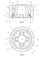
Fig. 7 corresponds substantially tofig. 6 and serves to schematically show the first angle ϕ and the second angle θ of the grindinggap 30. Thefrustoconical burr 3 is seen axially spaced from thering burr 2 to better illustrate these angles. - In the present case the height hb of the
ring burr 2 is smaller that the height hfb of thefrustoconical burr 3, however need not be so. The heights can be same or the ring burr be higher than the frustoconical burr. -
Fig. 7a illustrates the third line X3, which is at an angle γ with the longitudinal axis B through the centre of thering burr 2. This angle γ is very steep and can in some embodiments even be zero. The third line X3 extends between a thirdupper point 28 on an upper inscribed curve of the firstcurved teeth 10 of thering burr 2 at the grindinggap inlet 31 through a thirdlower point 29 on a lower inscribed curve of the firstcurved teeth 11 of thering burr 2 at theentry 25 of the grindinggap outlet 32 and intersects the longitudinal centre axis B of thering burr 2 at an angle γ.Fig. 7c shows the first angle ϕ between the first line X1 and the third line X3, andfig. 7b shows the second angle θ between the second line X2 and the third line X3. Thering burr 2 and thefrustoconical burr 3 are coaxially aligned. As is clear from thefigures 7a,7b,7b the second angle θ is greater than the first angle ϕ both being steeper than grinding gaps of known grinding units. Conventionally, there have been a prejudice to use grinding units with larger width of grinding gaps than specified in accordance with the present invention due to the apprehension that particles and granula could not enter the grinding gap appropriately to pass further down into the grinding gap and be properly grinded for a given purpose and a desired quality. As is clear fromfig. 7a,7b,7c the width of the grinding gap can be made wider by making a higher grinding unit while the grinding gap remains very steep. The inscribed curves is seen better infig. 11 . -
Fig. 8 is a bottom view of the grindingunit 1 seen infig. 4 seen from the bottom illustrating the opposite finerfourth teeth 11 of thering burr 2 opposite the finerthird teeth 24 of thefrustoconical burr 3 at the grindinggap 30outlet 32. - In
fig. 9 shows thefrustoconical burr 3 seen from thetop end 17a to illustrate that thecusps 21 of the first subset ofteeth 20a and thecusps 22 of the second subset ofteeth 20b defines a substantially squared outline. The second first circumscribed curve C4 is illustrated at the tapered ends 25 of the grindinggrooves 8. - In the top end view of the assembled grinding
unit 1 seen infig. 10 the first circumscribed circle C1 of the first subset ofcurved teeth 20a, the second circumscribed circle C2 of the second subset ofcurved teeth 20b, and the upper inscribed circle C3 of thefirst teeth 10 of thering burr 2 are sketched in, to illustrate the radii R1, R2, and R3 of these at the grindinggap inlet 31, and thus the variable width of the grindinggap 30. In the respective sets ofteeth 10;20a,20b R3 > R1 > R2. Thecollar 23 of finerthird teeth 24 of thebase 16 of thefrustoconical burr 3 is seen at the grindingoutlet 32. Thecusps 21 of the teeth of the first subset ofcurved teeth 20a are blunt or flat contrary to thecusps 22 of the teeth of the second subset ofcurved teeth 20b, which are more pointed or less blunt. -
Fig. 11 is a longitudinal sectional view seen inside thering burr 2 illustrating the lower inscribed curve C5 and the upper inscribe curve C4. - A
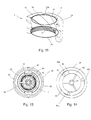
cartridge 34 for receiving the grindingunit 1 is seen in perspective infig. 12 , in a top view infig. 13 where the grinding unit is inserted, and in a bottom view infig. 14 , where the grindingunit 1 has not been inserted. - The
cartridge 34 has acartridge housing 35 and a detachablerotatable locking ring 36 suited to be accommodated in saidcartridge housing 35 for keeping the grindingunit 1 in operative grinding position inside saidcartridge housing 35. Thecartridge housing 35 has abottom housing 37 with abottom opening 38 for inserting the grindingunit 1, thebottom housing 37 has acircumferential shoulder 39 via which thebottom housing 37 extends into anupper part 40 configured for supplying matter to be grinded to the grindingunit 1. Theshoulder 39 of thebottom housing 37 has at least one firstinternal locking protrusion 33, as seen best infig. 14 , for engaging at least one complementary notch orgroove ring burr 2 to prevent rotation of thering burr 2 during grinding. Alogo 41 may be provided on any part of the cartridge housing, in the present case on thebottom housing 37. Theupper part 40 includes an anchor means 41 for a grindingshaft 42 rotationally mounted in relation to a grinder house (not shown) and operatively connected/connectable to thefrustoconical burr 3 to rotate saidfrustoconical burr 3 in relation to thering burr 2, and coupling means 43 for mounting thecartridge 34 inside a grinder house (not shown) with theshaft 42 accessible for performing the grinding operation. - The locking
ring 36 has three axially protruding lockingwebs internal guide grooves bottom housing 37. Aninternal guide groove free opening 38 of the bottom housing 37 a distance towards theshoulder 39 and into a radially extending sloping guide groove part (not shown). The axial guide groove part and the sloping guide groove part substantially form an L shape. The lockingring 36 has abridge member 46 than spans it's diameter and serves to avoid the grindingunit 1 dropping out of thecartridge housing 37 as well as a means for moving thefrustoconical burr 3 along the longitudinal axis A;B of the grindingunit 1 when adjusting the grindingoutlet 32 by rotating the lockingring 36. - The
cartridge 34 can also be used with conventional grinding units. - The superiority of the grinding unit according to the present invention is illustrated in the below Example.
- The grinding unit of the present invention has been manufactured and tested against two conventionally obtainable grinding units on the market:
- The Japanese grinding units used in Kyocera Conical Ceramic Burr Hand Turn Coffee, and a Chinese version being substantially a copy of these Japanese grinding units. The Chinese copy is substantial of same design as the Japanese, but differs in a very abrupt transition between first curved teeth and fourth curved teeth of the ring burr. Both had six second curved teeth, with three teeth in each of the first subset and the second subset of second curved teeth. The radius of the teeth of the first subset was larger than the radius of the teeth of the second subset and the teeth of a first subset were arranged on a frustoconical body alternating with teeth of the second subset.
- The aim of the test was to investigate how (time) efficient the grinding units were at grinding espresso coffee beans.
- A frustoconical burr of the present invention was given the dimensions:
- hfb = 29 mm
- Rb = 20 mm
- R1 = 14.5 mm
- R2 = 12 mm
- Where hfb is the height of the frustoconical burr, Rb is the radius of the base of frustoconical burr, R1 is the radius of the first circumscribed curve defined by the teeth of the first subset at a free top end of the frustoconical burr, and R2 is the radius of the second first circumscribed curve of the teeth of the second subset at the top end of the frustoconical burr.
- A corresponding ring burr of the present invention was given the dimensions:
- hrb = 25 mm
- R3 = 19 mm
- R4 = 18 mm
- Where hrb is the height of the ring burr, R3 is the radius of the inscribed curve of the first curved teeth of the ring burr at the grinding gap inlet, and R4 is the radius of the lower inscribed curve of the first curved teeth of the ring burr at the entry of the grinding gap outlet.
- The frustoconical burr was positioned in the opening of the ring burr in such as way that their longitudinal axes coincided, though displaced along their longitudinal axes relative to each other such that approximately
R3 - R2 = 6.4 mm
R3 - R1 = 3.6 mm
which resulted in a first angle of 9° and a second angle of 16°. The size of the grinded coffee beans were comparable to what is used for (finely sized) espresso. - For the Chinese and Japanese grinding units the similarly identified dimensions were approximately, hfb = 19mm, hrb - 15 mm, Rb = 15.5 mm, R1 = 10 mm, R2 = 8 mm, R3 = 14 mm, and R4 = 14 mm. Furthermore, the first and second angles are approximately 20° and 27°.
- The test was carried out by pouring coffee beans into the grinding unit, rotating the frustoconical burr 50 times around it's longitudinal axis, and weighing the amount of grinded coffee beans. The results were:
- Grinding unit according to the invention = 24 g
- Chinese grinding unit = 3.3 g
- Japanese grinding unit = 4.5 g
- The grinding unit of the present invention thus produced 7.3 times as much grinded coffee beans as the Chinese grinding unit, and 5.3 times as much grinded coffee beans as the Japanese grinding unit, even though hfb and hrb were only 1.5 and 1.7 times higher, respectively, and the gaps R3-R2 and R3-R1 were 6 and 4 mm, respectively, i.e. approximately similar. The grinding unit of the present invention thus grinded much more coffee beans, and thus was much more time efficient than the Chinese and the Japanese grinding units.
- Although the invention is described above in context with food products and for a manually operated grinding unit it should be understood that other kinds of particles than food product particles can be grinded, as well as a motor can be incorporated to operate the device.
- The cartridge can be dimensioned to fit conventional grinders and any particulate or granular matter be grinded by means of the grinding unit according to the present invention. Particles or granula can e.g. be between 2 - 15 mm and the height and weight sized and number of teeth adjusted so that the grinding inlet allows entry of such sizes and shapes of particles.
Claims (15)
- A grinding unit (1) comprising at least- a stationary ring burr (2) with an opening (4) for receiving a rotary frustoconical burr (3) to delimit a grinding gap (30) there between, which grinding gap (30) has an outlet (32) for grinded matter at a base (16) of the frustoconical burr (3) and an inlet (31) for matter to be grinded at the opposite top end (17a) of the frustoconical burr (3),- the ring burr (2) has an interior wall (9) provided with annularly spaced apart first curved teeth (10) protruding radially into the grinding gap (30), and- the frustoconical burr (3) has an annular exterior wall (19) provided with annularly spaced apart second curved teeth (20a;20b) protruding into the grinding gap (30), wherein- the second curved teeth (20a;20b) comprise a first subset of curved teeth (20a) and a second subset of curved teeth (20b) configured so that at least a part of the curved teeth of the first subset (20a) protrude longer into the grinding gap (30) than the second subset of curved teeth (20b), and so that the first subset of curved teeth (20a) and the second subset of curved teeth (20b) define axially extending grinding grooves (8) tapering towards the base (16) of the frustoconical burr (3),
characterised in that- a first line (X1) extends via a first upper point (21') on a first circumscribed curve (C1) of the teeth of the first subset of curved teeth (20a) at a free top end (17a) of the frustoconical burr (3) through a first lower point (21") on a second first circumscribed curve (C4) at tapered ends of the grinding grooves (8), and intersects a longitudinal axis (A) of the frustoconical burr (3),- a second line (X2) extends via a second upper point (22') on a second circumscribed curve (C2) of the teeth of the second subset of curved teeth (20b) at the free top end (17a) of the frustoconical burr (3) through a second lower point (22") on the second first circumscribed curve (C4) at tapered ends of the grinding grooves (8), and intersects a longitudinal axis (A) of the frustoconical burr (3),- a third line (X3) extends between a third point (28) on an upper inscribed curve (C3) of the first curved teeth (10) of the ring burr (2) at the grinding gap (30) inlet (31) through a third lower point (29) on a lower inscribed curve (C5) of the first curved teeth (10) of the ring burr (2) at the entry (25) of the grinding gap (30) outlet (32), and intersects or is parallel to the longitudinal axis (B) of the ring burr (2), wherein- a first angle ϕ between the first line (X1) and the third line (X3) is smaller than or equal to 15°, and- a second angle θ between the second line (X2) and the third line (X3) is smaller than or equal to 22°. - A grinding unit (1) according to claim 2, characterised in that- the first angle ϕ is smaller than or equal to 13°, preferably smaller than or equal to 11°, and more preferred smaller than or equal to 9, and/or- the second angle θ is smaller than or equal to 22°, and more preferred smaller than or equal to 20°, even more preferred smaller than or equal to 18°, and even more preferred smaller than or equal to 16°.
- A grinding unit (1) according to any of the claims 1 or 2, characterised in that the ring burr (2) and the frustoconical burr (3) have heights (hrb; hfb) selected to provide a grinding gap inlet (31) with a width sized in accordance with the size and shape of particles or granula to be grinded.
- A grinding unit (1) according to claim 3, characterised in that the height (hfb) of the frustoconical burr (3) is at least 65% of the diameter of the base of the frustoconical burr, preferably at least 67%, and more preferred at least 69%.
- A grinding unit (1) according to any of the preceding claims 1 - 4, characterised in that the number of teeth of the second curved teeth (20a;20b), at least at a top end (17a) of the frustoconical burr (3), is even, preferably the number is at least six, more preferred the number is eight.
- A grinding unit (1) according to any of the preceding claims 1 - 5, characterised in that a geometrical outline taken through the cusps (21;22) of the second curved teeth (20a,20b) at the top end (17a) of the frustoconical burr (3) opposite the base (16) is substantially square.
- A grinding unit (1) according to any of the preceding claims 1 - 6, characterised in that a tooth of the first subset of curved teeth (20a) is arranged alternate with a tooth of the second subset of curved teeth (20b).
- A grinding unit (1) according to any of the preceding claims 1 - 7, characterised in that at least one of the ring burr (2) and the frustoconical burr (3) are made of at least one ceramic material, preferably both the ring burr (2) and the frustoconical burr (3) are made of at least one ceramic material.
- A grinding unit (1) according to any of the preceding claims 1 - 8, characterised in that the ring burr (2) and/or the frustoconical burr (3) is/are axially displaceable along it's/their longitudinal axis (A;B).
- A grinding unit (1) according to any of the preceding claims 1 - 9, characterised in that a curvature of the first curved teeth (10) is a clockwise first threading, and a curvature of the second curved teeth (20a;20b) is a counter-clockwise second threading, or vice versa.
- A grinding unit (1) according to any of the preceding claims 1 - 10, characterised in that the teeth of the second curved teeth (20a;20b) divide into a multiplicity of finer curved third teeth (24) towards the base (16) of the frustoconical burr (3), and/or the teeth of the first curved teeth (10) divide into a multiplicity of finer curved fourth teeth (11) towards the base (12) of the ring burr (2).
- A cartridge (34) for the grinding unit (1) according to any of the preceding claims 1 - 11, characterised in that the cartridge (34) comprises a cartridge housing (35) and a detachable, locking ring (36), rotatable about it's central axis, for keeping the grinding unit (1) in operative grinding position inside the cartridge housing (35), the cartridge housing (35) comprises a bottom housing (37) with a bottom opening (38) for inserting the grinding unit (1), the bottom housing (37) has a circumferential inner shoulder (39) via which the bottom housing (37) extends into an upper part (40) configured for supplying matter to be grinded to the grinding unit (1), the shoulder (39) of the bottom housing (37) has at least one first locking protrusion (33) for engaging at least one complementary notch or groove (13a,13b,13c) of the ring burr (2) to prevent rotation of the ring burr (2) during grinding.
- A cartridge (34) according to claim 12, characterised in that the locking ring (36) has at least two axially protruding locking webs (44) fitting slidably into corresponding internal guide grooves (45) of the bottom housing (37), wherein an internal guide groove (45) has an axial guide groove part extending from the free opening (38) of the bottom housing (37) a distance towards the shoulder (39) into a radially extending sloping guide groove part.
- A cartridge (34) according to any of the claims 12 or 13, characterised in that the upper part (40) includes an anchor means (41) for a grinding shaft (42) rotationally mounted in a grinder house and operatively connected to the frustoconical burr (3), and coupling means (43) for mounting the cartridge (34) inside the grinder house with the grinding shaft (42) accessible for performing the grinding operation.
- Use of the grinding unit (1) according to any of the preceding claims 1 - 11 with or without the cartridge (34) according to any of the preceding claims 12, 13 or 14 for grinding coffee beans.
Priority Applications (8)
| Application Number | Priority Date | Filing Date | Title |
|---|---|---|---|
| EP13155230.9A EP2767201A1 (en) | 2013-02-14 | 2013-02-14 | A grinding unit, a cartridge for the grinding unit and use of same for grinding coffee beans |
| CA2899417A CA2899417C (en) | 2013-02-14 | 2014-02-13 | A grinding unit, a cartridge for the grinding unit and use of same for grinding coffee beans |
| AU2014217847A AU2014217847B2 (en) | 2013-02-14 | 2014-02-13 | A grinding unit, a cartridge for the grinding unit and use of same for grinding coffee beans |
| PCT/EP2014/052788 WO2014125006A1 (en) | 2013-02-14 | 2014-02-13 | A grinding unit, a cartridge for the grinding unit and use of same for grinding coffee beans |
| CN201480009044.9A CN105188495B (en) | 2013-02-14 | 2014-02-13 | Grinding unit, the purposes for the cylinder base of grinding unit and the grinding unit to ground coffee beans |
| US14/767,572 US9578989B2 (en) | 2013-02-14 | 2014-02-13 | Grinding unit, a cartridge for the grinding unit and use of same for grinding coffee beans |
| EP14709201.9A EP2956039B1 (en) | 2013-02-14 | 2014-02-13 | A grinding unit, a cartridge for the grinding unit and use of same for grinding coffee beans |
| DK14709201.9T DK2956039T3 (en) | 2013-02-14 | 2014-02-13 | A LOVE UNIT, A HOLDER FOR THE LOVE UNIT AND USING THE SAME TO MAKE COFFEE BEANS |
Applications Claiming Priority (1)
| Application Number | Priority Date | Filing Date | Title |
|---|---|---|---|
| EP13155230.9A EP2767201A1 (en) | 2013-02-14 | 2013-02-14 | A grinding unit, a cartridge for the grinding unit and use of same for grinding coffee beans |
Publications (1)
| Publication Number | Publication Date |
|---|---|
| EP2767201A1 true EP2767201A1 (en) | 2014-08-20 |
Family
ID=47683650
Family Applications (2)
| Application Number | Title | Priority Date | Filing Date |
|---|---|---|---|
| EP13155230.9A Withdrawn EP2767201A1 (en) | 2013-02-14 | 2013-02-14 | A grinding unit, a cartridge for the grinding unit and use of same for grinding coffee beans |
| EP14709201.9A Active EP2956039B1 (en) | 2013-02-14 | 2014-02-13 | A grinding unit, a cartridge for the grinding unit and use of same for grinding coffee beans |
Family Applications After (1)
| Application Number | Title | Priority Date | Filing Date |
|---|---|---|---|
| EP14709201.9A Active EP2956039B1 (en) | 2013-02-14 | 2014-02-13 | A grinding unit, a cartridge for the grinding unit and use of same for grinding coffee beans |
Country Status (7)
| Country | Link |
|---|---|
| US (1) | US9578989B2 (en) |
| EP (2) | EP2767201A1 (en) |
| CN (1) | CN105188495B (en) |
| AU (1) | AU2014217847B2 (en) |
| CA (1) | CA2899417C (en) |
| DK (1) | DK2956039T3 (en) |
| WO (1) | WO2014125006A1 (en) |
Cited By (3)
| Publication number | Priority date | Publication date | Assignee | Title |
|---|---|---|---|---|
| WO2016207740A1 (en) * | 2015-06-22 | 2016-12-29 | Patrick John Delbridge | Spice grinders |
| EP3202290A1 (en) * | 2016-02-03 | 2017-08-09 | Eugster/Frismag AG | Grinder, mill, device for preparing coffee with a mill and method of milling |
| WO2019020915A1 (en) * | 2017-07-28 | 2019-01-31 | Psp | Device for grinding food grains and mill comprising such a grinding device |
Families Citing this family (40)
| Publication number | Priority date | Publication date | Assignee | Title |
|---|---|---|---|---|
| WO2015113040A1 (en) | 2014-01-27 | 2015-07-30 | Hospi Corporation | Method and apparatus for preparing liquid suspensions and solutions from medications in pill or tablet form |
| TWM512994U (en) * | 2015-06-08 | 2015-12-01 | Jie-Chi Liu | A cup of coffee combiner |
| CN105167615B (en) * | 2015-09-15 | 2017-11-28 | 广东新宝电器股份有限公司 | A kind of coffee machine bean grinding system |
| EP3355982B1 (en) | 2015-10-02 | 2023-11-08 | Myers Devices, LLC | Aspiration apparatus and method of using the same |
| ITUB20159723A1 (en) * | 2015-12-16 | 2017-06-16 | Plast Emilia S R L | Grinding device |
| JP6887145B2 (en) * | 2016-07-25 | 2021-06-16 | 株式会社川▲崎▼合成樹脂 | Crusher |
| CN106622468B (en) * | 2016-12-06 | 2019-01-29 | 东阿阿胶股份有限公司 | A kind of donkey-hide gelatin pulverizer |
| CN106607135B (en) * | 2016-12-06 | 2019-01-22 | 东阿阿胶股份有限公司 | A kind of donkey-hide gelatin pulverizer fine lapping knife |
| CN106824414B (en) * | 2016-12-06 | 2019-01-15 | 东阿阿胶股份有限公司 | A kind of donkey-hide gelatin pulverizer fine lapping mechanism |
| CN114631744A (en) * | 2017-05-16 | 2022-06-17 | 尼科尔森设计顾问有限公司 | Bean grinding equipment |
| CA3010942A1 (en) * | 2017-07-18 | 2019-01-18 | Gruppo Cimbali S.P.A. | Device for resetting the position of the grinding wheels in a grinder |
| US10413127B1 (en) | 2017-07-27 | 2019-09-17 | Jana Media, LLC | Coffee grinder |
| IT201700118492A1 (en) * | 2017-10-19 | 2019-04-19 | Mazzer Luigi Spa | COFFEE GRINDER WITH REPOSITIONABLE SYSTEM FOR INDICATION OF THE POSITION OF THE MEANS OF ADJUSTMENT OF THE DISTANCE BETWEEN THE MILLS |
| USD901822S1 (en) * | 2017-11-17 | 2020-11-10 | Leo Martin Shapiro | Prayer wheel |
| CN108478043A (en) * | 2018-05-21 | 2018-09-04 | 广东万事泰电器有限公司 | Bean milling machine |
| US11619112B2 (en) | 2018-10-22 | 2023-04-04 | Halliburton Energy Services, Inc. | Rotating cutter apparatus for reducing the size of solid objects in a fluid |
| AT522032B1 (en) * | 2018-12-18 | 2021-11-15 | Joma Kunststofftechnik Gmbh | Grinder with convex curved grinding projections |
| WO2020180665A1 (en) * | 2019-03-04 | 2020-09-10 | Nypro Inc. | Improved spice grinder |
| AU2019271902B2 (en) * | 2019-04-26 | 2021-07-01 | Japan Porlex & Co., Ltd. | Mortar body and mill device |
| JP6731516B1 (en) * | 2019-05-07 | 2020-07-29 | 株式会社貝印刃物開発センター | Granular food mill |
| GB201913905D0 (en) * | 2019-09-26 | 2019-11-13 | Stasin Howard Robert | Condiment dispenser |
| EP3804586B1 (en) * | 2019-10-10 | 2022-01-26 | Hemro International AG | Coffee mill |
| AT523107B1 (en) * | 2019-11-04 | 2021-09-15 | Joma Kunststofftechnik Gmbh | Spice grinder part and manufacturing process for a spice grinder part |
| EP4076114A1 (en) * | 2019-12-18 | 2022-10-26 | Melitta Professional Coffee Solutions GmbH & Co. KG | Grinder, grinding disk for a grinder, and coffee machine having a grinder of this type |
| US11490765B2 (en) * | 2020-01-02 | 2022-11-08 | E-Link Plastic & Metal Industrial Co., Ltd. | Medicine grinder |
| US20210204756A1 (en) | 2020-01-03 | 2021-07-08 | Samson Bright Industrial Company Limited | Grinder |
| CN111166176A (en) * | 2020-01-17 | 2020-05-19 | 六安索伊电器制造有限公司 | Double-bean grinding device for coffee machine |
| ES1246489Y (en) * | 2020-03-06 | 2020-08-28 | Proyectos Y Ejecuciones S A | Grinder |
| CN113712450A (en) * | 2020-05-20 | 2021-11-30 | 漳州灿坤实业有限公司 | Bean grinding mechanism and bean grinding device |
| EP3912534A1 (en) * | 2020-05-18 | 2021-11-24 | Tsann Kuen (Zhangzhou) Enterprise Co., Ltd. | Coffee bean grinder |
| CN111530536B (en) * | 2020-05-25 | 2021-08-17 | 青岛农业大学 | Loss-prevention molecular biology experiment sample grinder |
| CN112386128B (en) * | 2020-11-16 | 2021-11-05 | 台州智子科技有限公司 | Raw material grinding device for coffee beverage |
| USD935832S1 (en) | 2021-03-05 | 2021-11-16 | Strategic Exits LLC | Coffee grinder |
| US11647865B2 (en) | 2021-03-05 | 2023-05-16 | Srategic Exits LLC | Conical burr hand grinder |
| CN215993719U (en) * | 2021-04-12 | 2022-03-11 | 宁波厨聚厨房科技有限公司 | Grinding machine core and grinding head used by same |
| CN113080723B (en) * | 2021-04-12 | 2022-10-04 | 宁波厨聚厨房科技有限公司 | Grinding machine core and grinding head used by same |
| USD945816S1 (en) | 2021-04-22 | 2022-03-15 | Strategic Exits LLC | Coffee grinder |
| CN113180500B (en) * | 2021-05-21 | 2023-07-25 | 东莞市贝跃五金电子有限公司 | Vertical straight row grinding knife set |
| CN217090442U (en) * | 2022-01-27 | 2022-08-02 | 宁波畅佳电子商务有限公司 | Grinding device |
| US11832766B2 (en) | 2022-02-14 | 2023-12-05 | Samson Bright Industrial Company Limited | Grinder |
Citations (5)
| Publication number | Priority date | Publication date | Assignee | Title |
|---|---|---|---|---|
| DE19514794A1 (en) | 1995-04-21 | 1996-10-24 | Peter Gass | Grinder for granular material like grain, coffee, pepper, salt or sugar |
| US6224005B1 (en) * | 1999-12-07 | 2001-05-01 | Yienn Lih Enterprise Co., Ltd. | Inner grinding member of a pepper grinder |
| EP1818100A1 (en) | 2006-02-13 | 2007-08-15 | Eldom Rothrist AG | Grinding device for granular material, especially for alimentary use |
| EP1818099A1 (en) | 2006-02-13 | 2007-08-15 | Eldom Rothrist AG | Grinding device for granular material, especially for alimentary use |
| EP2050377A1 (en) * | 2007-10-16 | 2009-04-22 | Eldom Rothrist AG | Grinding tool |
Family Cites Families (13)
| Publication number | Priority date | Publication date | Assignee | Title |
|---|---|---|---|---|
| FR1472524A (en) * | 1966-03-24 | 1967-03-10 | Broyeurs Menagers Soc D | Grinding process and processors for coffee, pepper or other granular products |
| DE1960314A1 (en) * | 1969-12-02 | 1971-06-03 | Licentia Gmbh | Grinding cone for a coffee grinder |
| US5052631A (en) * | 1987-08-24 | 1991-10-01 | Poncy George W | Peppermill tree |
| US4771954A (en) * | 1987-10-05 | 1988-09-20 | Poncy George W | Wooden peppermill tree |
| DE29506788U1 (en) | 1995-04-21 | 1995-08-17 | Gass Peter | Grinder for crushing granular material such as grain, coffee, pepper, salt or sugar |
| US7273005B2 (en) | 2004-06-18 | 2007-09-25 | Saeco Ipr Limited | Coffee grinder assembly for a coffee machine |
| FR2873559B1 (en) * | 2004-07-28 | 2008-04-18 | Psp Ind Sas Soc Par Actions Si | UNIVERSAL CASSETTE FOR THE ADJUSTMENT OF MILLING ON A CONDIMENT MILL, MECHANICAL OR ELECTRIC, OR ON AN APPARATUS FOR REDUCING FEED IN END PORTIONS |
| ITFI20060281A1 (en) | 2006-11-14 | 2008-05-15 | Saeco Ipr Ltd | GRINDING ORGANS FOR A COFFEE MILL DEVICE AND A COFFEE MACHINE INCLUDING SUCH A DEVICE. |
| CN201001652Y (en) * | 2007-02-06 | 2008-01-09 | 白宗仁 | Mills |
| WO2009047590A1 (en) * | 2007-10-12 | 2009-04-16 | Bich Francois | Grinding system, grinding mill for such grinding system and reload cartridge for such grinding system. |
| US7604192B2 (en) * | 2007-11-28 | 2009-10-20 | Samson Bright Industrial Company Limited | Grinding apparatus for a condiment grinder |
| CN102871564B (en) * | 2012-09-29 | 2014-11-26 | 宁波厨聚厨房科技有限公司 | Grinding device |
| EP2984973A1 (en) * | 2014-08-12 | 2016-02-17 | Jura Elektroapparate Ag | Grinder for grinding coffee beans and coffee machine with such a grinder |
-
2013
- 2013-02-14 EP EP13155230.9A patent/EP2767201A1/en not_active Withdrawn
-
2014
- 2014-02-13 US US14/767,572 patent/US9578989B2/en active Active
- 2014-02-13 CA CA2899417A patent/CA2899417C/en active Active
- 2014-02-13 WO PCT/EP2014/052788 patent/WO2014125006A1/en active Application Filing
- 2014-02-13 EP EP14709201.9A patent/EP2956039B1/en active Active
- 2014-02-13 CN CN201480009044.9A patent/CN105188495B/en active Active
- 2014-02-13 AU AU2014217847A patent/AU2014217847B2/en active Active
- 2014-02-13 DK DK14709201.9T patent/DK2956039T3/en active
Patent Citations (5)
| Publication number | Priority date | Publication date | Assignee | Title |
|---|---|---|---|---|
| DE19514794A1 (en) | 1995-04-21 | 1996-10-24 | Peter Gass | Grinder for granular material like grain, coffee, pepper, salt or sugar |
| US6224005B1 (en) * | 1999-12-07 | 2001-05-01 | Yienn Lih Enterprise Co., Ltd. | Inner grinding member of a pepper grinder |
| EP1818100A1 (en) | 2006-02-13 | 2007-08-15 | Eldom Rothrist AG | Grinding device for granular material, especially for alimentary use |
| EP1818099A1 (en) | 2006-02-13 | 2007-08-15 | Eldom Rothrist AG | Grinding device for granular material, especially for alimentary use |
| EP2050377A1 (en) * | 2007-10-16 | 2009-04-22 | Eldom Rothrist AG | Grinding tool |
Cited By (4)
| Publication number | Priority date | Publication date | Assignee | Title |
|---|---|---|---|---|
| WO2016207740A1 (en) * | 2015-06-22 | 2016-12-29 | Patrick John Delbridge | Spice grinders |
| EP3202290A1 (en) * | 2016-02-03 | 2017-08-09 | Eugster/Frismag AG | Grinder, mill, device for preparing coffee with a mill and method of milling |
| WO2019020915A1 (en) * | 2017-07-28 | 2019-01-31 | Psp | Device for grinding food grains and mill comprising such a grinding device |
| FR3069462A1 (en) * | 2017-07-28 | 2019-02-01 | Psp | FOOD SEED MILLING DEVICE AND MILL COMPRISING SUCH A MILLING DEVICE. |
Also Published As
| Publication number | Publication date |
|---|---|
| US20160015214A1 (en) | 2016-01-21 |
| EP2956039B1 (en) | 2017-05-24 |
| DK2956039T3 (en) | 2017-09-11 |
| EP2956039A1 (en) | 2015-12-23 |
| CA2899417A1 (en) | 2014-08-21 |
| AU2014217847B2 (en) | 2017-09-14 |
| AU2014217847A1 (en) | 2015-09-24 |
| US9578989B2 (en) | 2017-02-28 |
| CN105188495A (en) | 2015-12-23 |
| WO2014125006A1 (en) | 2014-08-21 |
| CA2899417C (en) | 2016-07-19 |
| CN105188495B (en) | 2017-09-29 |
Similar Documents
| Publication | Publication Date | Title |
|---|---|---|
| EP2767201A1 (en) | A grinding unit, a cartridge for the grinding unit and use of same for grinding coffee beans | |
| JP6990846B2 (en) | Electric flour grinder | |
| RU2683666C2 (en) | Grinder for grinding coffee beans as well as coffee machine comprising such grinder | |
| KR101935150B1 (en) | Grinding blade using vertical rollers and grinder having the same | |
| US9545174B2 (en) | Directly falling powder type coffee grinding machine | |
| CN207463350U (en) | A kind of fish meal disintegrating apparatus with grinding particle size adjustable function | |
| KR101932088B1 (en) | Coffee bean grinding apparatus | |
| US3952958A (en) | Grinder apparatus for wheat, grains, and the like | |
| KR101154088B1 (en) | Grinding case | |
| WO2019169994A1 (en) | Grinder provided with feeding screw | |
| CN104970678A (en) | Juice extractor | |
| JP6553724B2 (en) | Sandstone millstone | |
| US1987941A (en) | Feed grinder | |
| KR20200125895A (en) | Mortar and mill device | |
| WO2019058351A1 (en) | Freeze dried coffee with coffee grounds | |
| CN208177585U (en) | Grinder with feeding spiro rod | |
| CN202665315U (en) | Granular food grinding mill | |
| CN102715855B (en) | Grainy food grinding machine | |
| KR20170123356A (en) | Drip coffee Extractor Brewing using a millstone | |
| KR200490342Y1 (en) | Dispersion device of coffee powder applied to coffee machine | |
| JP6795815B2 (en) | Coffee bean grinder | |
| EP3954258A1 (en) | Automatic coffee machine having a grinder with a safety element | |
| CN213640631U (en) | Electric coffee bean grinder | |
| KR101257154B1 (en) | Home-use power Pulverizer | |
| KR200219303Y1 (en) | pepper crusher |
Legal Events
| Date | Code | Title | Description |
|---|---|---|---|
| PUAI | Public reference made under article 153(3) epc to a published international application that has entered the european phase |
Free format text: ORIGINAL CODE: 0009012 |
|
| 17P | Request for examination filed |
Effective date: 20130214 |
|
| AK | Designated contracting states |
Kind code of ref document: A1 Designated state(s): AL AT BE BG CH CY CZ DE DK EE ES FI FR GB GR HR HU IE IS IT LI LT LU LV MC MK MT NL NO PL PT RO RS SE SI SK SM TR |
|
| AX | Request for extension of the european patent |
Extension state: BA ME |
|
| STAA | Information on the status of an ep patent application or granted ep patent |
Free format text: STATUS: THE APPLICATION IS DEEMED TO BE WITHDRAWN |
|
| 18D | Application deemed to be withdrawn |
Effective date: 20150221 |