EP1817742B1 - Planar angular visualization of the bronchial tree - Google Patents
Planar angular visualization of the bronchial tree Download PDFInfo
- Publication number
- EP1817742B1 EP1817742B1 EP05806939.4A EP05806939A EP1817742B1 EP 1817742 B1 EP1817742 B1 EP 1817742B1 EP 05806939 A EP05806939 A EP 05806939A EP 1817742 B1 EP1817742 B1 EP 1817742B1
- Authority
- EP
- European Patent Office
- Prior art keywords
- tree structure
- anatomical
- planar
- visualization
- tree
- Prior art date
- Legal status (The legal status is an assumption and is not a legal conclusion. Google has not performed a legal analysis and makes no representation as to the accuracy of the status listed.)
- Expired - Lifetime
Links
Images




Classifications
-
- G—PHYSICS
- G06—COMPUTING OR CALCULATING; COUNTING
- G06T—IMAGE DATA PROCESSING OR GENERATION, IN GENERAL
- G06T7/00—Image analysis
- G06T7/10—Segmentation; Edge detection
- G06T7/11—Region-based segmentation
-
- G—PHYSICS
- G06—COMPUTING OR CALCULATING; COUNTING
- G06T—IMAGE DATA PROCESSING OR GENERATION, IN GENERAL
- G06T2207/00—Indexing scheme for image analysis or image enhancement
- G06T2207/10—Image acquisition modality
- G06T2207/10072—Tomographic images
- G06T2207/10081—Computed x-ray tomography [CT]
-
- G—PHYSICS
- G06—COMPUTING OR CALCULATING; COUNTING
- G06T—IMAGE DATA PROCESSING OR GENERATION, IN GENERAL
- G06T2207/00—Indexing scheme for image analysis or image enhancement
- G06T2207/30—Subject of image; Context of image processing
- G06T2207/30004—Biomedical image processing
- G06T2207/30101—Blood vessel; Artery; Vein; Vascular
Definitions
- This invention pertains in general to the field of medical imaging. More particularly the invention relates to a method and an apparatus for planar angular visualization of an anatomical tree structure, and more particularly to a planar topological mapping of a three-dimensional bronchial tree structure of the lungs.
- a patient In helical computed tomography (CT) imaging, a patient is advanced linearly through the examination region along a direction that is perpendicular to a gantry rotation plane to effectuate a helical orbiting of the x-ray source about the subject.
- X-ray absorption data obtained during the helical orbiting is reconstructed using filtered back projection or another reconstruction method to generate a three-dimensional image representation of the subject or of a selected portion thereof.
- High resolution CT data sets from multi-slice scanners allow the inspection of the bronchial down to smaller airways for diagnostic purposes.
- the resulting images can be used to inspect the airway lumen and wall thickness of the bronchia.
- Bartz D et Al.: "Hybrid segmentation and exploration of the human lungs", ISBN: 0-7803-8120-3 discloses a hybrid segmentation method based on a pipeline of three segmentation stages to extract the lower airways down to the seventh generation of the bronchi. User interacts to specify the seed point inside the easily detectable trachea at the upper end of the lower airways. The authors also disclose the segmentation of the complementary vascular tree of the lungs.
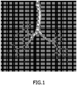
- the bronchial tree structure contains hundreds of sub-segments. Therefore, a visual inspection of all paths in the three-dimensional bronchial tree is very time consuming. On the other hand, a planar projection of the three-dimensional tree leads to multiple occlusions, as illustrated in Figure 1 , and the continuation of the specific airway path is difficult to follow, due to the delicate structure of the tree.
- an object of the present invention is to provide a system and method for providing an improved representation of a three-dimensional anatomical tree.
- the present invention preferably seeks to mitigate, alleviate or eliminate one or more of the above-identified deficiencies in the art and disadvantages singly or in any combination and solves at least the above mentioned problems by providing a system, an image acquisition device, a method, a computer-readable medium and an image workstation that provides a planar angular visualization of an anatomical tree according to the appended claims.
- the general solution according to the invention suggests a planar topological mapping of the three-dimensional bronchial tree structure of the lungs such that no occlusions or intersection of segments occur, that the hierarchy of the sub-segments is derivable, and that conveys a similarity to the true anatomical regions such as the lung lobes.
- this map allows inspection of the bronchial tree in a view, and with a low degree of freedom, for instance through a Graphical User Interface slider which varies the selected distance to the carina of all bronchial segments.
- a method for visualizing an anatomical tree structure which comprises the following steps.
- the anatomical tree structure is segmented from a three-dimensional image set of at least a portion of a body.
- a planar angular visualization of the anatomical tree structure is then determined.
- the planar angular visualization of the anatomical tree structure is then displayed.
- a system for visualizing an anatomical tree structure is disclosed.
- Segmenting means segments the anatomical tree structure from a three-dimensional image set of at least a portion of a body.
- Determination means determines a planar visualization of the anatomical tree structure.
- Displaying means displays the planar angular visualization of the anatomical tree structure.
- a computer-readable medium having embodied thereon a computer program, for automatic extraction of an anatomical tree structure, for processing by a computer.
- the computer program comprises a code segment for segmenting the anatomical tree structure from a three-dimensional image set of at least a portion of a body, a code segment for determining a planar angular visualization of the anatomical tree structure; and a code segment for displaying the planar angular visualization of the anatomical tree structure.
- the present invention has the advantage over the prior art that it provides a two-dimensional representation of an anatomical map in which occlusions or intersection of segments are minimized, i.e. do not occur, thus making the visual inspection of the paths of the anatomical tree much easier, thus facilitating subsequent automated or manual processing of the derived information, e.g. for analysis of the tree for anomalies.
- CT computed tomography
- MRI Magnetic Resonance Imaging
- PET Position Emission Tomography
- SPECT Single Photon Emission Computed Tomography
- the CT acquisition device 20 comprises a multi-array CT gantry 22 and a patient table 24 that can be positioned within the gantry 22.
- the patient table 24 supports a patient during acquisition of raw image data of the patient.
- the coarse image data is applied to a computer 26, which reconstructs volumetric image data of the raw image data.
- the computer 26 is programmed in such a manner that in conformity with the invention the computer 26 calculates a segmented tree of the tracheobronchial tree.
- the computer 26 determines a planar angular visualization of the anatomical tree structure, the tree and visualization being displayed on a display unit of the computer.
- the reconstructed volumetric image data can be transferred to an image processing system 28 for processing the data according to the method of the invention.
- This image processing system 28 may be a suitably programmed computer of a workstation 30.
- the workstation 30, which will be described in more detail below with reference to Figure 9 is connected to a screen 32.
- the system further comprises a microprocessor, a general purpose memory like random access memory (RAM) and a further memory that are being communicatively connected to each other through a software bus.
- the memory comprises computer readable software code designed to perform the method according to the invention.
- the memory is a display buffer that is designed to comprise the segmented tracheobronchial tree, the planar angular visualization and the original image set as previously described.
- the workstation 30 comprises a suitable storage reading device, like a CD-drive, that can read the software from the storage device. This CD-drive is then operatively connected to the software bus too.
- a person is x-rayed using a multi-slice CT and a 3-D data set representing the person's bronchial tree is created using a known manner in step 300.
- the bronchial tree is segmented from a three-dimensional image in step 302, as for instance based on the algorithm described in Schlatölter et al. (Simultaneous Segmentation and Tree Reconstruction of the Airways for Virtual Bronchoscopy, SPIE Conference on Medical Imaging, Proceedings of SPIE Vol. 4684, pp. 103-113 (2002 )).
- the unsupervised bronchial tree segmentation starts from the trachea and is based on a so-called front propagation approach.
- a region growing aggregates all voxels below a certain Hounsfield threshold. Whenever the growth front splits into different segments, a further region growing is started in each of the segments. "Leakages" into the parenchymal tissue is detected and stopped by monitoring a possible sudden increase of the growth front. After the region growing process is complete, then the centerlines (skeleton lines) of trachea, bronchi and smaller airways are extracted and a linked graph structure is built which represents the branching points of the tree structure.
- a planar angular visualization of the bronchial tree structure is then determined in step 304.
- the planar visualization of the bronchial tree structure is then displayed in step 306.
- the invention suggests a two-dimensional planar mapping of the bronchial tree, as illustrated in Figure 4 , such that no occlusions or intersection of segments occur, and that the hierarchy of the segments is obvious.
- the true geometric relations are not preserved, but the topological relations are true as for example in a typical subway map.
- the main segments point in the approximate direction of their true geometric location in a coronal projection wherein upper lung lobes (42, 41) are directed upwards and lower lung lobes (44, 43) are directed downwards as illustrated in Figures 4-5 .
- Figure 5 also illustrates a middle 45 lung lobe.
- the suggested planar mapping gives an overview of the bronchial tree in a single two-dimensional view, which is intuitively similar to the anatomical relations, as illustrated in Figure 5 .
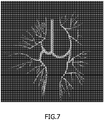
- the trachea 50 descends towards the center of the diagram, representing the carina, and then left and right main bronchi bifurcate at 90° angles. It will be understood by those skilled in the art that the angle could also be fixed at another value, for example, as illustrated in Figure 7 which will be described in more detail below.
- the plotted centerline branches with an equal angular step width to the left and right of the current angular direction. The angular step width decreases by a factor of 1 ⁇ 2 after each bifurcation.
- the bifurcations are characterized as the locations where in the above described region growing scheme the growth front has disintegrated (split).
- Each point in the mapping is given by angle and distance to the center of the diagram.
- the distance to the diagram center is proportional to the bronchial-path-distance to the carina, and the angle is determined by the number of previous bifurcations. So the length of a segment in the diagram is just given by the connection between the point positions determined as previously explained.
- the length of a segment in the diagram is not a true representation of its real length. This is not possible as the segments have to be spread out far enough to avoid overlapping. Rather, the radial distance is a true representation of the length of the airway back to the carina. In other words, the tangential distances in the diagram (on the circles) are just used to spread out the segments, but the radial distances are true.
- the direction of the branching in the diagram is controlled such that the one of the two subtrees which has the higher centroid (in foot-to-head direction) is chosen as the branch in the diagram which bends towards the top, whereas the other branch bends towards the bottom of the diagram.
- the colors or grey scale values of the displayed diagram may be chosen such as to reflect the anatomically differentiated lobes and main segments as illustrated in Fig. 10 . It will be understood by those skilled in the art that the actual displayed colors or grey scale values can be selected by the user to provide a visual image which is distinctive to the user.
- the diagram may be interactive in a way that a mouse click on a given point in the diagram will set another display device such as an orthoviewer directly to the place in the three-dimensional CT data set which is represented by the click-on point in the planar mapping.
- the diagram may be interactive in a way that a mouse click on a given point in the diagram selects the airway centreline path from this point to the trachea and displays further quantitative information along this path, such as lumen diameter, bronchial wall thickness, etc.
- the diagram may be interactive in a way that a mouse movement over a certain diagram region magnifies this region such that also higher orders of tree generations become discernable.
- a further feature allows the user to move a slider in a graphical user interface such that for all of the points in the tree which have the specified distance from the carina, a perpendicular reformatted image is shown in the corresponding position in the diagram and moving the slider allows changing the specified carina distance, as illustrated by the images in Figure 6 .
- An alternative display of the planar mapping indicating the airway lumen diameter in relation to the carina distance is illustrated in Fig. 7 .
- the diagram can be drawn such that the line thickness at each point of the diagram is proportional to the measured airway lumen diameter at the corresponding point in the bronchial tree.
- the different line thickness is illustrated in Fig. 7 .
- the diagram can be drawn such that smooth angular interpolation is used to give a more organic appearance as illustrated in Fig. 7 .
- the bifurcations are at the same positions as in Figs. 4-5 , wherein position is defined by the number of earlier bifurcations and length to carina, but between the bifurcation points the centreline points are linearly interpolated in their angle and radial distance ( ⁇ and ⁇ coordinate).
- the diagram can be drawn such that the bronchial wall thickness at each point of the diagram is proportional to the measured wall thickness at the corresponding point in the bronchial tree.
- Anomalies in the bronchial lumen diameter and wall thickness can be automatically detected and pointed out by markers or color coding at the respective positions in the diagram.
- another image processing module can find at each point of the bronchial tree the accompanying artery. The diameter of the accompanying artery can be automatically measured. Then the ratio between the bronchial diameter and the arterial diameter (which is an important clinical parameter) can be color-coded into each point of the planar mapping.
- planar mapping is to map the segmented pulmonary arterial vessel tree, and to render at each point of the graph the vessel diameter or any possibly detected anomalies. For example, at each point of the graph, the minimum projection of the CT-Hounsfield values at this vessel portion can be rendered, so that filling defects (caused by clots, and possibly indicating pulmonary embolisms) can be detected at a single glance.
- a computer-readable medium 100 has embodied thereon a computer program 110 for automatic extraction of a planar angular visualization of an anatomical tree from a 3D medical image 112, for processing by a computer 113.
- the computer program comprises a code segment 114 for segmenting the anatomical tree structure from a three-dimensional image set of at least a portion of a body, a code segment 115 for determining a planar angular visualization of the anatomical tree structure, a code segment 116 for displaying the planar angular visualization of the anatomical tree structure.
- Fig. 9 illustrates an exemplary medical image workstation 119 according to a further embodiment of the present invention.
- the medical workstation is arranged for implementing the method of the invention, and configured to receive and process a 3D medical image.
- the workstation is arranged to run the above described program code segments in order to perform the method according to the invention.
- the medical workstation 119 is configured for automatic extraction of a planar angular visualization of an anatomical tree from a 3D medical image, and comprises segmenting means 120 for segmenting the anatomical tree structure from a three-dimensional image set of at least a portion of a body, determination means 121 for determining a planar visualization of the anatomical tree structure, displaying means 122 for displaying the planar angular visualization of the anatomical tree structure.
- Said means 120-122 are preferably electronic components operatively connected to each other in a suitable way.
- Other components of the medical workstation as e.g. display(s) or pointer actuating devices are not illustrated or discussed in detail.
- the invention can be implemented in any suitable form including hardware, software, firmware or any combination of these. However, preferably, the invention is implemented as computer software running on one or more data processors and/or digital signal processors.
- the elements and components of an embodiment of the invention may be physically, functionally and logically implemented in any suitable way. Indeed, the functionality may be implemented in a single unit, in a plurality of units or as part of other functional units. As such, the invention may be implemented in a single unit, or may be physically and functionally distributed between different units and processors.
Landscapes
- Engineering & Computer Science (AREA)
- Computer Vision & Pattern Recognition (AREA)
- Physics & Mathematics (AREA)
- General Physics & Mathematics (AREA)
- Theoretical Computer Science (AREA)
- Apparatus For Radiation Diagnosis (AREA)
Priority Applications (1)
| Application Number | Priority Date | Filing Date | Title |
|---|---|---|---|
| EP05806939.4A EP1817742B1 (en) | 2004-11-23 | 2005-11-21 | Planar angular visualization of the bronchial tree |
Applications Claiming Priority (4)
| Application Number | Priority Date | Filing Date | Title |
|---|---|---|---|
| EP04106013 | 2004-11-23 | ||
| EP05102793 | 2005-04-08 | ||
| PCT/IB2005/053829 WO2006056923A1 (en) | 2004-11-23 | 2005-11-21 | Planar angular visualization of the bronchial tree |
| EP05806939.4A EP1817742B1 (en) | 2004-11-23 | 2005-11-21 | Planar angular visualization of the bronchial tree |
Publications (2)
| Publication Number | Publication Date |
|---|---|
| EP1817742A1 EP1817742A1 (en) | 2007-08-15 |
| EP1817742B1 true EP1817742B1 (en) | 2018-01-10 |
Family
ID=35814189
Family Applications (1)
| Application Number | Title | Priority Date | Filing Date |
|---|---|---|---|
| EP05806939.4A Expired - Lifetime EP1817742B1 (en) | 2004-11-23 | 2005-11-21 | Planar angular visualization of the bronchial tree |
Country Status (5)
| Country | Link |
|---|---|
| US (1) | US8045769B2 (https=) |
| EP (1) | EP1817742B1 (https=) |
| JP (1) | JP4871292B2 (https=) |
| CN (1) | CN101065771B (https=) |
| WO (1) | WO2006056923A1 (https=) |
Families Citing this family (21)
| Publication number | Priority date | Publication date | Assignee | Title |
|---|---|---|---|---|
| DE602006008113D1 (de) * | 2005-02-11 | 2009-09-10 | Philips Intellectual Property | Verfahren zur automatischen extraktion des lungenarterienbaums aus medizinischen 3d-bildern |
| ATE544133T1 (de) | 2008-04-18 | 2012-02-15 | Koninkl Philips Electronics Nv | Segmentierung von lungenarterien |
| US11464578B2 (en) | 2009-02-17 | 2022-10-11 | Inneroptic Technology, Inc. | Systems, methods, apparatuses, and computer-readable media for image management in image-guided medical procedures |
| WO2011092594A2 (en) | 2010-02-01 | 2011-08-04 | Superdimension, Ltd. | Region-growing algorithm |
| JP5584006B2 (ja) * | 2010-03-31 | 2014-09-03 | 富士フイルム株式会社 | 投影画像生成装置、投影画像生成プログラムおよび投影画像生成方法 |
| DE102012204063B4 (de) * | 2012-03-15 | 2021-02-18 | Siemens Healthcare Gmbh | Generierung von Visualisierungs-Befehlsdaten |
| JP5833994B2 (ja) * | 2012-09-20 | 2015-12-16 | 富士フイルム株式会社 | 画像処理装置および方法ならびにプログラム |
| CN104036484B (zh) | 2013-03-06 | 2017-08-08 | 东芝医疗系统株式会社 | 图像分割装置、图像分割方法和医学图像设备 |
| JP6080267B2 (ja) * | 2014-09-12 | 2017-02-15 | 富士フイルム株式会社 | 3次元オブジェクト分割出力装置およびその応用 |
| US9901406B2 (en) | 2014-10-02 | 2018-02-27 | Inneroptic Technology, Inc. | Affected region display associated with a medical device |
| US10188467B2 (en) | 2014-12-12 | 2019-01-29 | Inneroptic Technology, Inc. | Surgical guidance intersection display |
| US9949700B2 (en) * | 2015-07-22 | 2018-04-24 | Inneroptic Technology, Inc. | Medical device approaches |
| CN105224759B (zh) * | 2015-10-13 | 2018-03-20 | 张帆 | 一种人体解剖结构模型、植入物快速成型方法 |
| ES2815423T3 (es) * | 2016-02-05 | 2021-03-30 | Pulmonx Corp | Procedimientos, sistemas y dispositivos para analizar datos de imágenes pulmonares |
| CN110246126A (zh) * | 2019-06-14 | 2019-09-17 | 吉林大学第一医院 | 一种从肺部ct图像中提取末端支气管树的方法 |
| US11875459B2 (en) | 2020-04-07 | 2024-01-16 | Vida Diagnostics, Inc. | Subject specific coordinatization and virtual navigation systems and methods |
| CN111861988A (zh) * | 2020-06-09 | 2020-10-30 | 深圳市旭东数字医学影像技术有限公司 | 基于支气管的自动及半自动肺分叶分段的方法及其系统 |
| US12266111B2 (en) | 2020-11-27 | 2025-04-01 | Vida Diagnostics, Inc. | Visualization of sub-pleural regions |
| US12076158B2 (en) | 2021-02-05 | 2024-09-03 | Siemens Healthineers Ag | Intuitive display for rotator cuff tear diagnostics |
| CN114820919B (zh) * | 2022-03-09 | 2024-10-18 | 深圳湾实验室 | 符合真实解剖结构的人体全呼吸道模型构建方法及系统 |
| CN116245746B (zh) * | 2022-12-21 | 2025-08-19 | 杭州堃博生物科技有限公司 | 支气管树模型补全方法、装置及非易失性存储介质 |
Family Cites Families (10)
| Publication number | Priority date | Publication date | Assignee | Title |
|---|---|---|---|---|
| JPS575109A (en) * | 1980-06-10 | 1982-01-11 | Fanuc Ltd | Curved surface forming method |
| JP3030108B2 (ja) * | 1991-03-18 | 2000-04-10 | 日本板硝子株式会社 | 多分岐光回路 |
| JPH0696223A (ja) * | 1992-09-16 | 1994-04-08 | Matsushita Electric Ind Co Ltd | 木構造図描画装置 |
| FR2708166A1 (fr) * | 1993-07-22 | 1995-01-27 | Philips Laboratoire Electroniq | Procédé de traitement d'images numérisées pour la détection automatique de sténoses. |
| US6246784B1 (en) * | 1997-08-19 | 2001-06-12 | The United States Of America As Represented By The Department Of Health And Human Services | Method for segmenting medical images and detecting surface anomalies in anatomical structures |
| EP1275086A2 (en) * | 2000-04-07 | 2003-01-15 | Stephen R. Aylward | Systems and methods for tubular object processing |
| US7191119B2 (en) * | 2002-05-07 | 2007-03-13 | International Business Machines Corporation | Integrated development tool for building a natural language understanding application |
| JP4342784B2 (ja) * | 2002-09-27 | 2009-10-14 | ザイオソフト株式会社 | 分岐体のcpr画像表示処理方法、分岐体のcpr画像表示処理装置及びプログラム |
| GB2395880B (en) | 2002-11-27 | 2005-02-02 | Voxar Ltd | Curved multi-planar reformatting of three-dimensional volume data sets |
| US7469073B2 (en) * | 2004-05-24 | 2008-12-23 | Siemens Medical Solutions Usa, Inc. | Image-based method for detection and removal of small fragments in segmented three-dimensional volumes |
-
2005
- 2005-11-21 JP JP2007542441A patent/JP4871292B2/ja not_active Expired - Fee Related
- 2005-11-21 CN CN2005800401985A patent/CN101065771B/zh not_active Expired - Lifetime
- 2005-11-21 WO PCT/IB2005/053829 patent/WO2006056923A1/en not_active Ceased
- 2005-11-21 US US11/719,549 patent/US8045769B2/en active Active
- 2005-11-21 EP EP05806939.4A patent/EP1817742B1/en not_active Expired - Lifetime
Also Published As
| Publication number | Publication date |
|---|---|
| US8045769B2 (en) | 2011-10-25 |
| CN101065771B (zh) | 2011-05-18 |
| CN101065771A (zh) | 2007-10-31 |
| US20090148008A1 (en) | 2009-06-11 |
| WO2006056923A1 (en) | 2006-06-01 |
| JP4871292B2 (ja) | 2012-02-08 |
| EP1817742A1 (en) | 2007-08-15 |
| JP2008520319A (ja) | 2008-06-19 |
Similar Documents
| Publication | Publication Date | Title |
|---|---|---|
| EP1817742B1 (en) | Planar angular visualization of the bronchial tree | |
| US20250241551A1 (en) | System for vascular assessment | |
| US7599535B2 (en) | System and method for tree-model visualization for pulmonary embolism detection | |
| Sonka et al. | Rule-based detection of intrathoracic airway trees | |
| JP6080249B2 (ja) | 3次元画像表示装置および方法並びにプログラム | |
| US5891030A (en) | System for two dimensional and three dimensional imaging of tubular structures in the human body | |
| US10039510B2 (en) | Visualizing different types of airway wall abnormalities | |
| EP2104453B1 (en) | Visualizing a vascular structure | |
| CN102007515B (zh) | 用于对肺动脉进行分割的方法和系统 | |
| WO2005055008A2 (en) | Automated segmentation, visualization and analysis of medical images | |
| JP2006075599A (ja) | 管状の解剖学的構造の可視化方法 | |
| WO2012158676A1 (en) | Systems and methods for segmenting three dimensional image volumes | |
| EP1761897A1 (en) | Displaying a tracheobronchial tree | |
| Ropinski et al. | Multimodal vessel visualization of mouse aorta PET/CT scans | |
| US11875459B2 (en) | Subject specific coordinatization and virtual navigation systems and methods | |
| CN112884879B (zh) | 用于提供至少一个管状结构的二维展开图像的方法 | |
| Kiraly et al. | Virtual bronchoscopy for quantitative airway analysis | |
| WO2010001327A1 (en) | Processing anatomy and associated quantitative analysis data of tissue | |
| Andronikou et al. | Technical developments in postprocessing of paediatric airway imaging | |
| Yu et al. | Toward reliable multigenerational analysis of anatomical trees in 3D high-resolution CT images | |
| Kamal | Investigation of in Vivo Cardiac Chambers Composite Rendering | |
| Douek et al. | Image processing in contrast-enhanced MR angiography | |
| Rubin | Volumetric Analysis of Spiral CT Data |
Legal Events
| Date | Code | Title | Description |
|---|---|---|---|
| PUAI | Public reference made under article 153(3) epc to a published international application that has entered the european phase |
Free format text: ORIGINAL CODE: 0009012 |
|
| 17P | Request for examination filed |
Effective date: 20070625 |
|
| AK | Designated contracting states |
Kind code of ref document: A1 Designated state(s): AT BE BG CH CY CZ DE DK EE ES FI FR GB GR HU IE IS IT LI LT LU LV MC NL PL PT RO SE SI SK TR |
|
| DAX | Request for extension of the european patent (deleted) | ||
| RAP1 | Party data changed (applicant data changed or rights of an application transferred) |
Owner name: PHILIPS INTELLECTUAL PROPERTY & STANDARDS GMBH Owner name: KONINKLIJKE PHILIPS N.V. |
|
| 17Q | First examination report despatched |
Effective date: 20140901 |
|
| GRAP | Despatch of communication of intention to grant a patent |
Free format text: ORIGINAL CODE: EPIDOSNIGR1 |
|
| INTG | Intention to grant announced |
Effective date: 20170714 |
|
| GRAS | Grant fee paid |
Free format text: ORIGINAL CODE: EPIDOSNIGR3 |
|
| GRAA | (expected) grant |
Free format text: ORIGINAL CODE: 0009210 |
|
| REG | Reference to a national code |
Ref country code: DE Ref legal event code: R081 Ref document number: 602005053362 Country of ref document: DE Owner name: KONINKLIJKE PHILIPS N.V., NL Free format text: FORMER OWNERS: PHILIPS INTELLECTUAL PROPERTY & STANDARDS GMBH, 20099 HAMBURG, DE; KONINKLIJKE PHILIPS ELECTRONICS N.V., EINDHOVEN, NL Ref country code: DE Ref legal event code: R081 Ref document number: 602005053362 Country of ref document: DE Owner name: PHILIPS GMBH, DE Free format text: FORMER OWNERS: PHILIPS INTELLECTUAL PROPERTY & STANDARDS GMBH, 20099 HAMBURG, DE; KONINKLIJKE PHILIPS ELECTRONICS N.V., EINDHOVEN, NL |
|
| AK | Designated contracting states |
Kind code of ref document: B1 Designated state(s): AT BE BG CH CY CZ DE DK EE ES FI FR GB GR HU IE IS IT LI LT LU LV MC NL PL PT RO SE SI SK TR |
|
| REG | Reference to a national code |
Ref country code: GB Ref legal event code: FG4D |
|
| REG | Reference to a national code |
Ref country code: CH Ref legal event code: EP Ref country code: AT Ref legal event code: REF Ref document number: 963168 Country of ref document: AT Kind code of ref document: T Effective date: 20180115 |
|
| REG | Reference to a national code |
Ref country code: IE Ref legal event code: FG4D |
|
| REG | Reference to a national code |
Ref country code: DE Ref legal event code: R096 Ref document number: 602005053362 Country of ref document: DE |
|
| REG | Reference to a national code |
Ref country code: DE Ref legal event code: R081 Ref document number: 602005053362 Country of ref document: DE Owner name: PHILIPS GMBH, DE Free format text: FORMER OWNERS: KONINKLIJKE PHILIPS N.V., EINDHOVEN, NL; PHILIPS INTELLECTUAL PROPERTY & STANDARDS GMBH, 20099 HAMBURG, DE Ref country code: DE Ref legal event code: R081 Ref document number: 602005053362 Country of ref document: DE Owner name: KONINKLIJKE PHILIPS N.V., NL Free format text: FORMER OWNERS: KONINKLIJKE PHILIPS N.V., EINDHOVEN, NL; PHILIPS INTELLECTUAL PROPERTY & STANDARDS GMBH, 20099 HAMBURG, DE |
|
| REG | Reference to a national code |
Ref country code: DE Ref legal event code: R084 Ref document number: 602005053362 Country of ref document: DE |
|
| REG | Reference to a national code |
Ref country code: GB Ref legal event code: 746 Effective date: 20180322 |
|
| REG | Reference to a national code |
Ref country code: NL Ref legal event code: MP Effective date: 20180110 |
|
| REG | Reference to a national code |
Ref country code: AT Ref legal event code: MK05 Ref document number: 963168 Country of ref document: AT Kind code of ref document: T Effective date: 20180110 |
|
| PG25 | Lapsed in a contracting state [announced via postgrant information from national office to epo] |
Ref country code: NL Free format text: LAPSE BECAUSE OF FAILURE TO SUBMIT A TRANSLATION OF THE DESCRIPTION OR TO PAY THE FEE WITHIN THE PRESCRIBED TIME-LIMIT Effective date: 20180110 |
|
| PG25 | Lapsed in a contracting state [announced via postgrant information from national office to epo] |
Ref country code: LT Free format text: LAPSE BECAUSE OF FAILURE TO SUBMIT A TRANSLATION OF THE DESCRIPTION OR TO PAY THE FEE WITHIN THE PRESCRIBED TIME-LIMIT Effective date: 20180110 Ref country code: CY Free format text: LAPSE BECAUSE OF FAILURE TO SUBMIT A TRANSLATION OF THE DESCRIPTION OR TO PAY THE FEE WITHIN THE PRESCRIBED TIME-LIMIT Effective date: 20180110 Ref country code: FI Free format text: LAPSE BECAUSE OF FAILURE TO SUBMIT A TRANSLATION OF THE DESCRIPTION OR TO PAY THE FEE WITHIN THE PRESCRIBED TIME-LIMIT Effective date: 20180110 Ref country code: ES Free format text: LAPSE BECAUSE OF FAILURE TO SUBMIT A TRANSLATION OF THE DESCRIPTION OR TO PAY THE FEE WITHIN THE PRESCRIBED TIME-LIMIT Effective date: 20180110 |
|
| PG25 | Lapsed in a contracting state [announced via postgrant information from national office to epo] |
Ref country code: AT Free format text: LAPSE BECAUSE OF FAILURE TO SUBMIT A TRANSLATION OF THE DESCRIPTION OR TO PAY THE FEE WITHIN THE PRESCRIBED TIME-LIMIT Effective date: 20180110 Ref country code: PL Free format text: LAPSE BECAUSE OF FAILURE TO SUBMIT A TRANSLATION OF THE DESCRIPTION OR TO PAY THE FEE WITHIN THE PRESCRIBED TIME-LIMIT Effective date: 20180110 Ref country code: BG Free format text: LAPSE BECAUSE OF FAILURE TO SUBMIT A TRANSLATION OF THE DESCRIPTION OR TO PAY THE FEE WITHIN THE PRESCRIBED TIME-LIMIT Effective date: 20180410 Ref country code: GR Free format text: LAPSE BECAUSE OF FAILURE TO SUBMIT A TRANSLATION OF THE DESCRIPTION OR TO PAY THE FEE WITHIN THE PRESCRIBED TIME-LIMIT Effective date: 20180411 Ref country code: SE Free format text: LAPSE BECAUSE OF FAILURE TO SUBMIT A TRANSLATION OF THE DESCRIPTION OR TO PAY THE FEE WITHIN THE PRESCRIBED TIME-LIMIT Effective date: 20180110 Ref country code: LV Free format text: LAPSE BECAUSE OF FAILURE TO SUBMIT A TRANSLATION OF THE DESCRIPTION OR TO PAY THE FEE WITHIN THE PRESCRIBED TIME-LIMIT Effective date: 20180110 Ref country code: IS Free format text: LAPSE BECAUSE OF FAILURE TO SUBMIT A TRANSLATION OF THE DESCRIPTION OR TO PAY THE FEE WITHIN THE PRESCRIBED TIME-LIMIT Effective date: 20180510 |
|
| REG | Reference to a national code |
Ref country code: DE Ref legal event code: R097 Ref document number: 602005053362 Country of ref document: DE |
|
| PG25 | Lapsed in a contracting state [announced via postgrant information from national office to epo] |
Ref country code: EE Free format text: LAPSE BECAUSE OF FAILURE TO SUBMIT A TRANSLATION OF THE DESCRIPTION OR TO PAY THE FEE WITHIN THE PRESCRIBED TIME-LIMIT Effective date: 20180110 Ref country code: IT Free format text: LAPSE BECAUSE OF FAILURE TO SUBMIT A TRANSLATION OF THE DESCRIPTION OR TO PAY THE FEE WITHIN THE PRESCRIBED TIME-LIMIT Effective date: 20180110 Ref country code: RO Free format text: LAPSE BECAUSE OF FAILURE TO SUBMIT A TRANSLATION OF THE DESCRIPTION OR TO PAY THE FEE WITHIN THE PRESCRIBED TIME-LIMIT Effective date: 20180110 |
|
| PLBE | No opposition filed within time limit |
Free format text: ORIGINAL CODE: 0009261 |
|
| STAA | Information on the status of an ep patent application or granted ep patent |
Free format text: STATUS: NO OPPOSITION FILED WITHIN TIME LIMIT |
|
| PG25 | Lapsed in a contracting state [announced via postgrant information from national office to epo] |
Ref country code: SK Free format text: LAPSE BECAUSE OF FAILURE TO SUBMIT A TRANSLATION OF THE DESCRIPTION OR TO PAY THE FEE WITHIN THE PRESCRIBED TIME-LIMIT Effective date: 20180110 Ref country code: CZ Free format text: LAPSE BECAUSE OF FAILURE TO SUBMIT A TRANSLATION OF THE DESCRIPTION OR TO PAY THE FEE WITHIN THE PRESCRIBED TIME-LIMIT Effective date: 20180110 Ref country code: DK Free format text: LAPSE BECAUSE OF FAILURE TO SUBMIT A TRANSLATION OF THE DESCRIPTION OR TO PAY THE FEE WITHIN THE PRESCRIBED TIME-LIMIT Effective date: 20180110 |
|
| 26N | No opposition filed |
Effective date: 20181011 |
|
| PG25 | Lapsed in a contracting state [announced via postgrant information from national office to epo] |
Ref country code: SI Free format text: LAPSE BECAUSE OF FAILURE TO SUBMIT A TRANSLATION OF THE DESCRIPTION OR TO PAY THE FEE WITHIN THE PRESCRIBED TIME-LIMIT Effective date: 20180110 |
|
| REG | Reference to a national code |
Ref country code: CH Ref legal event code: PL |
|
| PG25 | Lapsed in a contracting state [announced via postgrant information from national office to epo] |
Ref country code: LU Free format text: LAPSE BECAUSE OF NON-PAYMENT OF DUE FEES Effective date: 20181121 Ref country code: MC Free format text: LAPSE BECAUSE OF FAILURE TO SUBMIT A TRANSLATION OF THE DESCRIPTION OR TO PAY THE FEE WITHIN THE PRESCRIBED TIME-LIMIT Effective date: 20180110 |
|
| REG | Reference to a national code |
Ref country code: BE Ref legal event code: MM Effective date: 20181130 |
|
| REG | Reference to a national code |
Ref country code: IE Ref legal event code: MM4A |
|
| PG25 | Lapsed in a contracting state [announced via postgrant information from national office to epo] |
Ref country code: LI Free format text: LAPSE BECAUSE OF NON-PAYMENT OF DUE FEES Effective date: 20181130 Ref country code: CH Free format text: LAPSE BECAUSE OF NON-PAYMENT OF DUE FEES Effective date: 20181130 |
|
| PG25 | Lapsed in a contracting state [announced via postgrant information from national office to epo] |
Ref country code: IE Free format text: LAPSE BECAUSE OF NON-PAYMENT OF DUE FEES Effective date: 20181121 |
|
| PG25 | Lapsed in a contracting state [announced via postgrant information from national office to epo] |
Ref country code: BE Free format text: LAPSE BECAUSE OF NON-PAYMENT OF DUE FEES Effective date: 20181130 |
|
| PG25 | Lapsed in a contracting state [announced via postgrant information from national office to epo] |
Ref country code: TR Free format text: LAPSE BECAUSE OF FAILURE TO SUBMIT A TRANSLATION OF THE DESCRIPTION OR TO PAY THE FEE WITHIN THE PRESCRIBED TIME-LIMIT Effective date: 20180110 |
|
| PG25 | Lapsed in a contracting state [announced via postgrant information from national office to epo] |
Ref country code: PT Free format text: LAPSE BECAUSE OF FAILURE TO SUBMIT A TRANSLATION OF THE DESCRIPTION OR TO PAY THE FEE WITHIN THE PRESCRIBED TIME-LIMIT Effective date: 20180110 |
|
| PG25 | Lapsed in a contracting state [announced via postgrant information from national office to epo] |
Ref country code: HU Free format text: LAPSE BECAUSE OF FAILURE TO SUBMIT A TRANSLATION OF THE DESCRIPTION OR TO PAY THE FEE WITHIN THE PRESCRIBED TIME-LIMIT; INVALID AB INITIO Effective date: 20051121 |
|
| PGFP | Annual fee paid to national office [announced via postgrant information from national office to epo] |
Ref country code: FR Payment date: 20211126 Year of fee payment: 17 |
|
| PGFP | Annual fee paid to national office [announced via postgrant information from national office to epo] |
Ref country code: GB Payment date: 20221122 Year of fee payment: 18 |
|
| PG25 | Lapsed in a contracting state [announced via postgrant information from national office to epo] |
Ref country code: FR Free format text: LAPSE BECAUSE OF NON-PAYMENT OF DUE FEES Effective date: 20221130 |
|
| GBPC | Gb: european patent ceased through non-payment of renewal fee |
Effective date: 20231121 |
|
| PG25 | Lapsed in a contracting state [announced via postgrant information from national office to epo] |
Ref country code: GB Free format text: LAPSE BECAUSE OF NON-PAYMENT OF DUE FEES Effective date: 20231121 |
|
| PG25 | Lapsed in a contracting state [announced via postgrant information from national office to epo] |
Ref country code: GB Free format text: LAPSE BECAUSE OF NON-PAYMENT OF DUE FEES Effective date: 20231121 |
|
| PGFP | Annual fee paid to national office [announced via postgrant information from national office to epo] |
Ref country code: DE Payment date: 20241128 Year of fee payment: 20 |
|
| REG | Reference to a national code |
Ref country code: DE Ref legal event code: R071 Ref document number: 602005053362 Country of ref document: DE |