EP1817601B1 - Procede et appareil pour la mesure de la concentration d'hydrogene dans des constituants d'alliage de zirconium dans une piscine d'une centrale nucleaire - Google Patents
Procede et appareil pour la mesure de la concentration d'hydrogene dans des constituants d'alliage de zirconium dans une piscine d'une centrale nucleaire Download PDFInfo
- Publication number
- EP1817601B1 EP1817601B1 EP05851307A EP05851307A EP1817601B1 EP 1817601 B1 EP1817601 B1 EP 1817601B1 EP 05851307 A EP05851307 A EP 05851307A EP 05851307 A EP05851307 A EP 05851307A EP 1817601 B1 EP1817601 B1 EP 1817601B1
- Authority
- EP
- European Patent Office
- Prior art keywords
- fuel rod
- nuclear fuel
- calibration
- calibration standard
- eddy current
- Prior art date
- Legal status (The legal status is an assumption and is not a legal conclusion. Google has not performed a legal analysis and makes no representation as to the accuracy of the status listed.)
- Not-in-force
Links
Images


Classifications
-
- G—PHYSICS
- G21—NUCLEAR PHYSICS; NUCLEAR ENGINEERING
- G21C—NUCLEAR REACTORS
- G21C17/00—Monitoring; Testing ; Maintaining
- G21C17/06—Devices or arrangements for monitoring or testing fuel or fuel elements outside the reactor core, e.g. for burn-up, for contamination
-
- G—PHYSICS
- G01—MEASURING; TESTING
- G01R—MEASURING ELECTRIC VARIABLES; MEASURING MAGNETIC VARIABLES
- G01R33/00—Arrangements or instruments for measuring magnetic variables
- G01R33/02—Measuring direction or magnitude of magnetic fields or magnetic flux
- G01R33/028—Electrodynamic magnetometers
-
- G—PHYSICS
- G01—MEASURING; TESTING
- G01N—INVESTIGATING OR ANALYSING MATERIALS BY DETERMINING THEIR CHEMICAL OR PHYSICAL PROPERTIES
- G01N33/00—Investigating or analysing materials by specific methods not covered by groups G01N1/00 - G01N31/00
- G01N33/20—Metals
- G01N33/202—Constituents thereof
- G01N33/2022—Non-metallic constituents
-
- G—PHYSICS
- G01—MEASURING; TESTING
- G01N—INVESTIGATING OR ANALYSING MATERIALS BY DETERMINING THEIR CHEMICAL OR PHYSICAL PROPERTIES
- G01N33/00—Investigating or analysing materials by specific methods not covered by groups G01N1/00 - G01N31/00
- G01N33/20—Metals
- G01N33/208—Coatings, e.g. platings
-
- Y—GENERAL TAGGING OF NEW TECHNOLOGICAL DEVELOPMENTS; GENERAL TAGGING OF CROSS-SECTIONAL TECHNOLOGIES SPANNING OVER SEVERAL SECTIONS OF THE IPC; TECHNICAL SUBJECTS COVERED BY FORMER USPC CROSS-REFERENCE ART COLLECTIONS [XRACs] AND DIGESTS
- Y02—TECHNOLOGIES OR APPLICATIONS FOR MITIGATION OR ADAPTATION AGAINST CLIMATE CHANGE
- Y02E—REDUCTION OF GREENHOUSE GAS [GHG] EMISSIONS, RELATED TO ENERGY GENERATION, TRANSMISSION OR DISTRIBUTION
- Y02E30/00—Energy generation of nuclear origin
- Y02E30/30—Nuclear fission reactors
Definitions
- the present invention relates generally to a method of measuring hydrogen concentration in conductive materials.
- the present invention relates to a method of measuring hydrogen concentration in nuclear fuel rod claddings using eddy current techniques.
- the current method for determining hydrogen concentration in nuclear fuel rods is a destructive method, involving cutting samples out of the rod. These samples must be shipped to a laboratory that is equipped to handle radioactive materials for analysis. The analysis is a slow and expensive analytical process, requiring skilled operators and complicated equipment. Consequently, the number of analytical samples processed is relatively small, compared to the total sample population. This leads to a poor statistical representation of the fuel rod population, which may result in premature discharge of fuel rods, or more importantly, may lead to the use of fuel rods past their safe operating lifetime. Therefore, while this method is accurate, the fact that it is destructive, requires off-site analysis, and is slow limits its usefulness.
- In-situ methods of hydrogen measurement are available. However, these in-situ methods involve indirect measurements and assumptions which, if untrue, lead to large errors in hydrogen concentration.
- One such method measures a parameter different than hydrogen concentration, the zirconium oxide thickness, which is then correlated to hydrogen concentration using certain assumptions.
- Zirconium oxide is formed at the surface of fuel rods in the reaction between the zirconium cladding and the water used as a moderator in light water reactors. During operation of the reactor, the high temperatures at the surface of fuel rods cause the water to react with the surface. The hydrogen left after the oxygen from the water has reacted either absorbs into the cladding or remains in the water. Generally, a significant fraction of the available hydrogen is absorbed by the metal.
- the zirconium oxide-based analysis proceeds as follows.
- the thickness of the zirconium oxide layer is determined using an eddy current probe pressed against the surface of the fuel rod.
- This technique uses a probe containing a metal coil of wire, excited with radio-frequency alternating current, to induce a current, called an eddy current, in the fuel rod cladding.
- the induced eddy current in turn induces a back EMF in the probe coil and changes the probe impedance.
- the induced eddy current and probe impedance are dependent upon how close the probe is to the cladding, the effective electrical conductivity of the cladding, the effective magnetic permeability of any material between the probe and the cladding, and, if the excitation frequency is low enough, the thickness of the cladding.
- United States Patent No. 5,889,401 to Jourdain, et al. discloses a refinement to the above approach in which measurements are iteratively fit to a mathematical model of the probe and its interaction with the fuel rod and environment to estimate zirconium oxide and crud thickness.
- This method has been extended to include measurement of hydride in United States Patent No. 6,541,964 , also to Jourdain et al.
- theses methods still do not directly measure the parameter of interest, hydrogen concentration.
- the former patent is only useful for oxide and crud measurement, while the latter patent still depends on an indirect, iterative, mathematical model approach.
- United States Patent No. 6,541,964 does not address a number of key complications, including fuel rod temperature, temperature gradients, and inhomogeneous hydrogen concentrations.
- the measurement should preferably be made in-situ and should be independent of the temperature at which the measurement is performed.
- the present invention provides a method for measuring hydrogen concentration in an electrically conductive material according to the appended claims.
- the electrically conductive material is a nuclear fuel road including its cladding.
- a calibration standard is used that represents background variables that may affect the eddy current probe response, such as zirconium oxide thickness, ferromagnetic and non-ferromagnetic crud thickness, effective crud permeability, fuel rod temperature and combinations thereof.
- the method of the present invention is useful for in-situ measurement of hydrogen in nuclear power plant fuel rod claddings. This method eliminates the expense of destructively examining fuel rods. Furthermore, it eliminates uncertainty present with other eddy current methods in which hydrogen concentration is estimated by measurement of cladding oxide thickness.
- Fig. 1 is a process flow diagram according to one embodiment of the present invention.
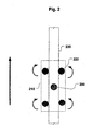
- Fig. 2 is a schematic diagram of a movable probe mount and a calibration standard according to an embodiment of the invention.
- Fig. 3 is a schematic diagram of a calibration standard and a fuel rod according to one embodiment of the present invention.
- the present invention provides a method for measuring any parameter of interest in a particular sample using an eddy current probe.
- the probe may be used to measure hydrogen concentration in a piece or section of metal, such as the hydrogen concentration in the cladding of a nuclear fuel rod.
- the eddy current probe is calibrated using a calibration standard that provides varying amounts of the parameter of interest in a material or substrate that represents the sample to be measured.
- the calibration standard may be a piece of metal having varying hydrogen concentrations similar, to the piece of metal or sample to be measured. The calibrated probe is then used to measure the parameter of interest in a given sample.
- a probe attached to an eddy current measurement device is brought into contact with a calibration standard.
- the eddy current probe used in this invention is preferably a surface probe.
- the probe should contact the surface in a reproducible manner to prevent a decrease in sensitivity due to inadequate contact with the surface.
- contacting the surface in a reproducible manner is accomplished through the use of spring-loading, which provides constant pressure sensor-to-surface contact.
- the probe will preferably be oriented perpendicular to the surface of the calibration standard with little or no variation from the perpendicular direction.
- the area(s) selected for measurement should be as similar as possible in geometry to each other. Differences in geometry such as curves, edges or other types of discontinuities may affect eddy current response and lead to errors in concentration measurement.
- the calibration standard is measured at a predetermined number of frequencies and locations, where each location contains a known level of the parameter of interest and representative values of the background variables.
- the calibration standard would have varying levels of the parameter of interest extending beyond the range expected in the in-situ measurements, as well as having representative levels of background variables that may affect the measurement of the sample.
- the eddy current probe response is dependent upon the electrical conductivity of the calibration standard, which, in turn, is dependent upon the level of the parameter of interest in the standard, such as hydrogen concentration.
- Fig. 2 is a schematic diagram of a movable probe mount and a calibration standard according to an embodiment of the invention.
- the eddy current probe 200 is brought into contact with the surface of the calibration standard 230.
- the probe 200 is held using a mount 210 that allows the probe 200 to traverse the length of the calibration standard 230.
- the mount 210 further includes a mode of automatically traversing the calibration standard, such as wheels 220 powered by an electric motor (not shown).
- the purpose of the mount 210 is to allow reproducible sample-to-probe contact pressure, as well as to allow the probe 200 to be moved along the length of the sample and calibration standard 230 at a reproducible rate.
- the probe response from the calibration standard 230 is measured as the probe 200 moves along the standard.
- calibration standards are, in general, fabricated to duplicate the size, shape, and construction material of the fuel rod measured as closely as possible.
- the calibration standards should contain varying amounts of hydrogen, preferably encompassing the concentration range of hydrogen expected, with the exception that the standard contains no fissionable material. For instance, if the highest concentration of hydrogen expected is approximately 500 parts per million (ppm), the highest concentration standard should contain at least this concentration. Preferably, the concentration of the highest standard should be at least 25 percent more than the highest concentration expected.
- the distribution of the varying parameter levels in each calibration standard point is determined by routine destructive and nondestructive techniques capable of measuring hydrogen concentration, e.g., hot vacuum extraction, and imaging hydride platelets within the cladding wall, e.g., metallography.
- Fuel rod cladding is often constructed of ZIRCALOY TM -4 in a tubular shape. Therefore, in a preferred embodiment, the calibration standard should be constructed of ZIRCALOY TM -4 material, in a tubular configuration, of approximately the same dimension as the fuel rods. Typically the cladding wall thickness is the order of 0.6 mm.
- Hydrogen-charged samples are prepared by any of a number of methods known to the art, such as electrochemical deposition or elevated temperature exposure of the metal standard to flowing hydrogen gas. In a preferred embodiment, the samples are prepared by flowing hydrogen gas in combination with thermal cycling. The distribution of hydrogen across the calibration standard is controlled through the application of differing temperature gradients across the standard. Alternatively, the standards may be prepared by flowing hydrogen across the standard, then subsequently applying heat in the manner described above.
- the calibration standard may also be used for temperature calibration.
- a calibration standard would include a source of heat to produce the same temperature and possibly temperature gradient across the calibration standard.
- the heat source is an internal electrical heater rod.
- any other type of suitable heat source may be used, such as a heat exchange coil or circulating water bath or heating tape attached to the calibration standard.
- it is often not necessary to perform a rigorous temperature calibration for each set of measurements.
- it is possible to quantify the relationship between cladding temperature and eddy current response in a separate activity, such as a laboratory environment. Any temperature gradient through the cladding wall can often be accounted for analytically, or, if sufficiently small, ignored.
- only one temperature calibration measurement is performed at the OD of the fuel rod cladding.
- One method of measuring temperature at the OD would be using a thermocouple, for instance.
- the minimum number of frequencies to be measured at each point along the calibration standard is dependent upon the number of significant independent background variables.
- Each data point collected at each frequency is composed of two components, a resistance component and a reactance component (in some measurement instruments the in-phase component and the quadrature component, or the amplitude and phase angle of the response). Therefore, when N different frequencies are measured, 2N sets of data result.
- the method can suppress the effects of 2N-1 background variables. Thus if there are three background variables, two frequencies are required. If there are five background variables, three frequencies are required. The greater the number of background variables to be suppressed the higher the data precision required.
- three background variables are assumed to have significant effects on the eddy current response: zirconium oxide thickness, effective crud permeability and fuel rod temperature.
- ⁇ 50.3 * ⁇ / f * ⁇ r 1 / 2
- ⁇ is the electromagnetic depth of penetration (skin depth) in mm
- p is the electrical resistivity in micro ohm cm
- f is the electromagnetic frequency in Hz
- ⁇ r is the relative magnetic permeability.
- one frequency may be 25 MHz
- a second frequency may be 10 MHz.
- the depths of penetration are the order of 0.085 mm and 0.135 mm, respectively, and only approximately 15% and 25% of the ZIRCALOYTM cladding wall is penetrated.
- An example calibration test matrix may include 10 or more test points. Test matrices may be derived using design of experiment techniques or through other methods known in the art. Below is a representative 15 point test matrix (in this example, "Magnetic Crud Layers" refers to a relative value proportional to the eddy current response obtained from measuring a crud layer of non-specified thickness and composition, i.e., a value of "2" represents twice the measured eddy current probe response that a value of "1" does): Test Point Number Hydrogen (ppm) ZrO 2 (microns) Magnetic Crud Layers Temperature (°C) 1 0 0 0 30 2 300 0 0 30 3 600 0 0 30 4 0 0 0 40 5 300 100 0 40 6 600 0 0 40 7 0 50 0 30 8 300 0 1 30 9 600 100 0 30 10 0 100 2 40 11 300 0 2 40 12 600 50 1 40 13 0 0 0 30 14 300 50 1 30 15 600 0 2 30
- B N and C N are constants
- X 1 and R 1 are the reactance and resistance at frequency 1
- X 2 and R 2 are the reactance and resistance at frequency 2
- X N and R N are the reactance and resistance at frequency N.
- the constants can be determined if the detailed relationship between the physical parameter and the eddy current response parameters are known, or, as in a preferred embodiment, if a set of at least 2N+1 measurements are made on the calibration standard. Better results may be obtained if 4N or more measurements are made with a best fit used to determine the 2N+1 calibration constants. This approach is rigorously correct for a small range of the physical parameter measured. For a larger range, higher order terms can be included in the expansion, or the expansion can be repeated at different nominal values.
- the fuel rod sample is measured.
- the outside surface temperatures of the cladding are measured using a thermocouple in contact with the outside of the fuel rod.
- the same sensor, eddy current instrument, cabling, test frequencies, voltage levels input to sensor, and measurement procedures as used in the calibration phase may be used.
- the parameter of interest hydrogen concentration in this embodiment, is calculated using the calibration constants determined as described above. With the calculated constants and the values of R i and X i obtained from the sample measurements, the hydrogen concentration is calculated at each point of interest.
- the calculation may be done remotely using a desktop computer and commercially-available software packages. Spreadsheet-based software packages, for instance, may be adequate for many applications. Alternatively, the software code necessary to perform this calculation may be resident in the data-handling system of the eddy current measurement device and the hydrogen concentration calculated in real time.
- the outer surface temperature is read from a thermocouple 315 attached to the calibration standard 320. If desired or necessary, temperature calibration measurements may be done alternatively in a laboratory setting. In yet another embodiment, after a sufficient number of calibrations have been performed on a given fuel rod type, a large enough database may exist to allow for calculation of the temperature effect, thus eliminating the need for a separate temperature measurement.
- calibration constants are calculated from the calibration measurements, and hydrogen concentrations for each sample point are calculated using the calibration constants and nuclear fuel rod data.
- hydrogen concentrations are displayed using whatever means are convenient and appropriate. Possible means include digital meter readout, analog meter readout, computer display, or operator notation. Typical units for display will be ppm hydrogen.
- the same methodology may be used by first calibrating the eddy current probe using a calibration standard that has known amounts of the parameter of interest and is also configured to similar the material or substrate against which the eddy current probe will be used. Therefore, the scope of the invention should not be limited by the specific disclosure herein.
Landscapes
- Physics & Mathematics (AREA)
- Engineering & Computer Science (AREA)
- Condensed Matter Physics & Semiconductors (AREA)
- General Physics & Mathematics (AREA)
- Plasma & Fusion (AREA)
- General Engineering & Computer Science (AREA)
- High Energy & Nuclear Physics (AREA)
- Monitoring And Testing Of Nuclear Reactors (AREA)
- Investigating Or Analyzing Materials By The Use Of Magnetic Means (AREA)
- Investigating And Analyzing Materials By Characteristic Methods (AREA)
Claims (16)
- Procédé de mesure de la concentration d'hydrogène dans un matériau électriquement conducteur, consistant à :étalonner (120) une sonde de courant de Foucault à une pluralité de concentrations d'hydrogène, dans lequel ledit étalonnage comprend la mesure (115) de courants de Foucault à une pluralité de positions le long d'un étalon ;mesurer (125) des courants de Foucault à une pluralité de positions le long d'un matériau électriquement conducteur ; etcalculer (130) une concentration d'hydrogène dans ledit matériau électriquement conducteur à chacune desdites positions le long dudit matériau électriquement conducteur,dans lequel ledit étalon comprend une variable d'arrière-plan qui simule ladite variable d'arrière-plan présente dans ledit matériau électriquement conducteur, dans lequel ladite variable d'arrière-plan est sélectionnée dans le groupe consistant en une épaisseur d'oxyde de zirconium, une épaisseur brute, une perméabilité brute effective, une température de barre de combustible et des combinaisons de celles-ci.
- Procédé selon la revendication 1, dans lequel ledit étalonnage comprend en outre la mesure desdits courants de Foucault à ladite pluralité de positions le long dudit étalon à une pluralité de fréquences à chacune desdites positions le long dudit étalon.
- Procédé selon la revendication 2, dans lequel ladite pluralité de fréquences est dans la plage de 1 KHz à 40 MHz.
- Procédé selon la revendication 2, dans lequel ladite pluralité de fréquences est d'environ 2 à environ 10.
- Procédé selon la revendication 2, dans lequel ledit étalonnage fournit un ensemble de données d'étalonnage, et dans lequel ledit calcul comprend le calcul d'un ensemble de constantes d'étalonnage en utilisant un développement en série de Taylor sur la base dudit ensemble de données d'étalonnage et le calcul de ladite concentration d'hydrogène sur la base dudit ensemble de constantes d'étalonnage.
- Procédé selon la revendication 1, dans lequel ledit matériau électriquement conducteur est une gaine de barre de combustible nucléaire.
- Procédé selon la revendication 1, dans lequel ledit matériau électriquement conducteur est un alliage de zirconium.
- Procédé selon la revendication 1, dans lequel le matériau électriquement conducteur comprend une barre de combustible nucléaire comportant une gaine, et dans lequel :ledit étalonnage d'une sonde de courant de Foucault à une pluralité de concentrations d'hydrogène comprend la mesure de courants de Foucault le long d'une barre de combustible nucléaire étalon disposée dans un bassin d'eau ;ladite mesure de courants de Foucault à une pluralité de positions comprend la mesure à une pluralité de positions le long de la barre de combustible nucléaire disposée adjacente à ladite barre de combustible nucléaire étalon dans ledit bassin d'eau ; etledit calcul d'une concentration d'hydrogène comprend le calcul d'une concentration d'hydrogène dans ladite barre de combustible nucléaire à chacune desdites positions le long de ladite barre de combustible nucléaire.
- Procédé selon la revendication 8, dans lequel ledit étalonnage comprend en outre la mesure desdits courants de Foucault à ladite pluralité de positions le long de ladite barre de combustible nucléaire étalon à une pluralité de fréquences à chacune desdites positions le long de ladite barre de combustible nucléaire étalon.
- Procédé selon la revendication 9, dans lequel ladite pluralité de fréquences est dans la plage de 1 KHz à 40 MHz.
- Procédé selon la revendication 9, dans lequel ladite pluralité de fréquences est d'environ 2 à environ 10.
- Procédé selon la revendication 9, dans lequel ledit étalonnage fournit un ensemble de données d'étalonnage, et dans lequel ledit calcul comprend le calcul d'un ensemble de constantes d'étalonnage en utilisant un développement en série de Taylor sur la base dudit ensemble de données d'étalonnage et le calcul de ladite concentration d'hydrogène sur la base dudit ensemble de constantes d'étalonnage.
- Procédé selon la revendication 9, dans lequel ladite barre de combustible nucléaire étalon comprend une variable d'arrière-plan qui simule ladite variable d'arrière-plan présente dans ladite barre de combustible nucléaire, dans lequel ladite variable d'arrière-plan est sélectionnée dans le groupe consistant en une épaisseur d'oxyde de zirconium, une épaisseur brute, une perméabilité brute effective, une température de barre de combustible et des combinaisons de celles-ci.
- Système de mesure d'une concentration d'hydrogène dans une barre de combustible nucléaire (330), comprenant :une sonde de courant de Foucault (200, 310) pour mesurer des courants de Foucault à une pluralité de positions le long d'une barre de combustible nucléaire ;une barre de combustible nucléaire étalon (320) pour étalonner ladite sonde de courant de Foucault à une pluralité de concentrations d'hydrogène ;un système de manipulation de données pour collecter les mesures de courant de Foucault générées par ladite sonde de courant de Foucault et pour calculer une concentration d'hydrogène à chacune de la pluralité de positions en utilisant les mesures de courant de Foucault,dans lequel ladite barre de combustible nucléaire étalon comprend une variable d'arrière-plan configurée pour simuler ladite variable d'arrière-plan présente dans ladite barre de combustible nucléaire, dans lequel ladite variable d'arrière-plan est sélectionnée dans le groupe consistant en une épaisseur d'oxyde de zirconium, une épaisseur brute, une perméabilité brute effective, une température de barre de combustible et des combinaisons de celles-ci.
- Système selon la revendication 14, comprenant en outre un support (325) configuré pour contenir ladite barre de combustible nucléaire étalon et une barre de combustible nucléaire à mesurer.
- Système selon la revendication 14, comprenant en outre un support de sonde (305) mobile configuré pour contenir ladite sonde de courant de Foucault et pour se déplacer le long d'une longueur de ladite barre de combustible nucléaire étalon et de la barre de combustible nucléaire à mesurer.
Applications Claiming Priority (2)
| Application Number | Priority Date | Filing Date | Title |
|---|---|---|---|
| US11/001,405 US7388369B2 (en) | 2004-11-30 | 2004-11-30 | Method and apparatus for measuring hydrogen concentration in zirconium alloy components in the fuel pool of a nuclear power plant |
| PCT/US2005/039666 WO2006060102A2 (fr) | 2004-11-30 | 2005-10-25 | Procede et appareil pour la mesure de la concentration d'hydrogene dans des constituants d'alliage de zirconium dans une piscine d'une centrale nucleaire |
Publications (3)
| Publication Number | Publication Date |
|---|---|
| EP1817601A2 EP1817601A2 (fr) | 2007-08-15 |
| EP1817601A4 EP1817601A4 (fr) | 2010-03-03 |
| EP1817601B1 true EP1817601B1 (fr) | 2011-07-06 |
Family
ID=36565487
Family Applications (1)
| Application Number | Title | Priority Date | Filing Date |
|---|---|---|---|
| EP05851307A Not-in-force EP1817601B1 (fr) | 2004-11-30 | 2005-10-25 | Procede et appareil pour la mesure de la concentration d'hydrogene dans des constituants d'alliage de zirconium dans une piscine d'une centrale nucleaire |
Country Status (4)
| Country | Link |
|---|---|
| US (1) | US7388369B2 (fr) |
| EP (1) | EP1817601B1 (fr) |
| AT (1) | ATE515710T1 (fr) |
| WO (1) | WO2006060102A2 (fr) |
Cited By (3)
| Publication number | Priority date | Publication date | Assignee | Title |
|---|---|---|---|---|
| US11662300B2 (en) | 2019-09-19 | 2023-05-30 | Westinghouse Electric Company Llc | Apparatus for performing in-situ adhesion test of cold spray deposits and method of employing |
| US11898986B2 (en) | 2012-10-10 | 2024-02-13 | Westinghouse Electric Company Llc | Systems and methods for steam generator tube analysis for detection of tube degradation |
| US11935662B2 (en) | 2019-07-02 | 2024-03-19 | Westinghouse Electric Company Llc | Elongate SiC fuel elements |
Families Citing this family (6)
| Publication number | Priority date | Publication date | Assignee | Title |
|---|---|---|---|---|
| SE530770C2 (sv) * | 2005-08-24 | 2008-09-09 | Westinghouse Electric Sweden | System och användning avseende virvelströmsmätningar på komponenter för nukleära reaktorer |
| TW201003672A (en) * | 2008-06-09 | 2010-01-16 | Westinghouse Electric Sweden | Method comprising measurement on fuel channels of fuel assemblies for nuclear boiling water reactors |
| US8203336B2 (en) * | 2009-09-13 | 2012-06-19 | Atomic Energy Council Institute Of Nuclear Energy Research | Eddy current probes having magnetic gap |
| KR101200781B1 (ko) * | 2011-07-08 | 2012-11-13 | 한전원자력연료 주식회사 | 프로브 및 이를 포함하는 연료봉 산화막 두께 측정장치 |
| KR101906855B1 (ko) * | 2017-07-25 | 2018-10-11 | 한전원자력연료 주식회사 | 이동형 핵연료 집합체 구조 변형 측정장비의 스탠다드 |
| CA3018475A1 (fr) * | 2017-09-29 | 2019-03-29 | Krassimir Stoev | Procedes et systemes d'essai d'un objet |
Citations (1)
| Publication number | Priority date | Publication date | Assignee | Title |
|---|---|---|---|---|
| JP2004101281A (ja) * | 2002-09-06 | 2004-04-02 | Tokyo Electric Power Co Inc:The | 核燃料部材中の水素濃度の非破壊測定方法 |
Family Cites Families (8)
| Publication number | Priority date | Publication date | Assignee | Title |
|---|---|---|---|---|
| US4402904A (en) | 1980-12-18 | 1983-09-06 | Combustion Engineering, Inc. | Method for determining clad integrity of a nuclear fuel rod |
| US5341678A (en) | 1993-05-12 | 1994-08-30 | General Electric Company | Method for determining thickness of ferromagnetic material deposition on nuclear fuel rods |
| SE508354C2 (sv) * | 1996-07-05 | 1998-09-28 | Asea Atom Ab | Förfarande och anordning för bestämning av skikttjocklek |
| SE515544C2 (sv) * | 1998-11-26 | 2001-08-27 | Westinghouse Atom Ab | Förfarande och anordning för bestämning av hydridinnehåll |
| US6366083B1 (en) | 1999-09-17 | 2002-04-02 | Framatome Anp Inc. | Method for measuring the thickness of oxide layer underlying crud layer containing ferromagnetic material on nuclear fuel rods |
| US6369566B1 (en) | 1999-09-27 | 2002-04-09 | Framatone Anp Inc. | Method for measuring crud thickness on nuclear fuel rods |
| JP4083382B2 (ja) | 2000-12-11 | 2008-04-30 | 日本核燃料開発株式会社 | 核燃料集合体用部材の水素濃度測定方法 |
| US6583618B2 (en) * | 2001-09-21 | 2003-06-24 | Framatome, Anp Inc. | Remote magnetic field material analyzer and method |
-
2004
- 2004-11-30 US US11/001,405 patent/US7388369B2/en not_active Expired - Fee Related
-
2005
- 2005-10-25 EP EP05851307A patent/EP1817601B1/fr not_active Not-in-force
- 2005-10-25 AT AT05851307T patent/ATE515710T1/de not_active IP Right Cessation
- 2005-10-25 WO PCT/US2005/039666 patent/WO2006060102A2/fr active Application Filing
Patent Citations (1)
| Publication number | Priority date | Publication date | Assignee | Title |
|---|---|---|---|---|
| JP2004101281A (ja) * | 2002-09-06 | 2004-04-02 | Tokyo Electric Power Co Inc:The | 核燃料部材中の水素濃度の非破壊測定方法 |
Cited By (3)
| Publication number | Priority date | Publication date | Assignee | Title |
|---|---|---|---|---|
| US11898986B2 (en) | 2012-10-10 | 2024-02-13 | Westinghouse Electric Company Llc | Systems and methods for steam generator tube analysis for detection of tube degradation |
| US11935662B2 (en) | 2019-07-02 | 2024-03-19 | Westinghouse Electric Company Llc | Elongate SiC fuel elements |
| US11662300B2 (en) | 2019-09-19 | 2023-05-30 | Westinghouse Electric Company Llc | Apparatus for performing in-situ adhesion test of cold spray deposits and method of employing |
Also Published As
| Publication number | Publication date |
|---|---|
| WO2006060102A3 (fr) | 2007-06-21 |
| EP1817601A4 (fr) | 2010-03-03 |
| US7388369B2 (en) | 2008-06-17 |
| EP1817601A2 (fr) | 2007-08-15 |
| ATE515710T1 (de) | 2011-07-15 |
| WO2006060102A2 (fr) | 2006-06-08 |
| US20070279050A1 (en) | 2007-12-06 |
Similar Documents
| Publication | Publication Date | Title |
|---|---|---|
| EP1817601B1 (fr) | Procede et appareil pour la mesure de la concentration d'hydrogene dans des constituants d'alliage de zirconium dans une piscine d'une centrale nucleaire | |
| CA1237773A (fr) | Methode et instrument pour mesurer l'epaisseur de la doublure en zircone dans un tube fait d'un alliage de zircone | |
| EP0664435A2 (fr) | Détermination de l'épaisseur | |
| US6366083B1 (en) | Method for measuring the thickness of oxide layer underlying crud layer containing ferromagnetic material on nuclear fuel rods | |
| US6369566B1 (en) | Method for measuring crud thickness on nuclear fuel rods | |
| JP4895142B2 (ja) | 酸化膜厚さ測定方法 | |
| Cai et al. | Quantitative evaluation of electrical conductivity inside stress corrosion crack with electromagnetic NDE methods | |
| Tesfalem et al. | Study of asymmetric gradiometer sensor configurations for eddy current based non-destructive testing in an industrial environment | |
| RU2246144C2 (ru) | Способ и устройство контроля газового зазора технологического канала уран-графитового ядерного реактора | |
| Vary | Nondestructive evaluation technique guide | |
| Deeds et al. | Determination of multiple properties with multiple eddy-current measurements | |
| Gros et al. | Determining confounding sensitivities in eddy current thin film measurements | |
| Dodd | Applications of a Phase-Sensitive Eddy-Current Instrument | |
| Dodd et al. | EDDY-CURRENT EVALUATION OF NUCLEAR CONTROL RODS. | |
| JPS58166203A (ja) | 核燃料用被覆管内面コ−テイング膜厚測定法ならびにその装置 | |
| Thorpe et al. | Eddy Current Measurement of Electrical Resistivity in Heat Treated Zr-2.5% Nb Pressure Tubes | |
| JPS59170706A (ja) | ジルカロイクラツドハフニウム中性子吸収棒のクラツド層の厚さ測定方法 | |
| Kent et al. | Design Optimization and Measurement Uncertainty of an Electromagnetic Level Sensor for Liquid Metal Reactors | |
| Bennett | Enhancing the Capabilities of the CANDU® Gap Probe | |
| CN117554427A (zh) | 基于电阻的铜比测量方法、装置、计算机设备和存储介质 | |
| Alencar et al. | Eddy current NDT: a suitable tool to measure oxide layer thickness in PWR fuel rods | |
| Smirnova et al. | Determination of the composition of the deposits and thickness of the oxide film on the surface of VVÉR and RBMK fuel elements | |
| Martin et al. | Characterization of irradiated fuel rods using pulsed eddy current techniques | |
| JPS6367506A (ja) | 核燃料被覆管のライニング厚さ測定方法およびその装置 | |
| Schankula et al. | AECL hot-cell facilities and post-irradiation examination services |
Legal Events
| Date | Code | Title | Description |
|---|---|---|---|
| PUAI | Public reference made under article 153(3) epc to a published international application that has entered the european phase |
Free format text: ORIGINAL CODE: 0009012 |
|
| 17P | Request for examination filed |
Effective date: 20070606 |
|
| AK | Designated contracting states |
Kind code of ref document: A2 Designated state(s): AT BE BG CH CY CZ DE DK EE ES FI FR GB GR HU IE IS IT LI LT LU LV MC NL PL PT RO SE SI SK TR |
|
| AX | Request for extension of the european patent |
Extension state: AL BA HR MK YU |
|
| DAX | Request for extension of the european patent (deleted) | ||
| A4 | Supplementary search report drawn up and despatched |
Effective date: 20100201 |
|
| RIC1 | Information provided on ipc code assigned before grant |
Ipc: G01N 33/20 20060101ALI20100126BHEP Ipc: G01R 33/028 20060101ALI20100126BHEP Ipc: G01R 33/12 20060101AFI20070709BHEP Ipc: G01N 27/02 20060101ALI20100126BHEP Ipc: G01N 27/72 20060101ALI20100126BHEP |
|
| 17Q | First examination report despatched |
Effective date: 20100419 |
|
| GRAC | Information related to communication of intention to grant a patent modified |
Free format text: ORIGINAL CODE: EPIDOSCIGR1 |
|
| GRAP | Despatch of communication of intention to grant a patent |
Free format text: ORIGINAL CODE: EPIDOSNIGR1 |
|
| RIC1 | Information provided on ipc code assigned before grant |
Ipc: G01N 33/20 20060101ALI20110307BHEP Ipc: G01R 33/028 20060101ALI20110307BHEP Ipc: G01N 27/72 20060101ALI20110307BHEP Ipc: G01N 27/02 20060101ALI20110307BHEP Ipc: G01R 33/12 20060101AFI20110307BHEP |
|
| GRAS | Grant fee paid |
Free format text: ORIGINAL CODE: EPIDOSNIGR3 |
|
| GRAA | (expected) grant |
Free format text: ORIGINAL CODE: 0009210 |
|
| AK | Designated contracting states |
Kind code of ref document: B1 Designated state(s): AT BE BG CH CY CZ DE DK EE ES FI FR GB GR HU IE IS IT LI LT LU LV MC NL PL PT RO SE SI SK TR |
|
| REG | Reference to a national code |
Ref country code: GB Ref legal event code: FG4D |
|
| REG | Reference to a national code |
Ref country code: CH Ref legal event code: EP |
|
| REG | Reference to a national code |
Ref country code: IE Ref legal event code: FG4D |
|
| REG | Reference to a national code |
Ref country code: DE Ref legal event code: R096 Ref document number: 602005028923 Country of ref document: DE Effective date: 20110825 |
|
| REG | Reference to a national code |
Ref country code: CH Ref legal event code: NV Representative=s name: SERVOPATENT GMBH |
|
| REG | Reference to a national code |
Ref country code: SE Ref legal event code: TRGR |
|
| REG | Reference to a national code |
Ref country code: NL Ref legal event code: VDEP Effective date: 20110706 |
|
| PG25 | Lapsed in a contracting state [announced via postgrant information from national office to epo] |
Ref country code: SI Free format text: LAPSE BECAUSE OF FAILURE TO SUBMIT A TRANSLATION OF THE DESCRIPTION OR TO PAY THE FEE WITHIN THE PRESCRIBED TIME-LIMIT Effective date: 20110706 |
|
| REG | Reference to a national code |
Ref country code: AT Ref legal event code: MK05 Ref document number: 515710 Country of ref document: AT Kind code of ref document: T Effective date: 20110706 |
|
| PG25 | Lapsed in a contracting state [announced via postgrant information from national office to epo] |
Ref country code: FI Free format text: LAPSE BECAUSE OF FAILURE TO SUBMIT A TRANSLATION OF THE DESCRIPTION OR TO PAY THE FEE WITHIN THE PRESCRIBED TIME-LIMIT Effective date: 20110706 Ref country code: NL Free format text: LAPSE BECAUSE OF FAILURE TO SUBMIT A TRANSLATION OF THE DESCRIPTION OR TO PAY THE FEE WITHIN THE PRESCRIBED TIME-LIMIT Effective date: 20110706 Ref country code: BE Free format text: LAPSE BECAUSE OF FAILURE TO SUBMIT A TRANSLATION OF THE DESCRIPTION OR TO PAY THE FEE WITHIN THE PRESCRIBED TIME-LIMIT Effective date: 20110706 Ref country code: IS Free format text: LAPSE BECAUSE OF FAILURE TO SUBMIT A TRANSLATION OF THE DESCRIPTION OR TO PAY THE FEE WITHIN THE PRESCRIBED TIME-LIMIT Effective date: 20111106 Ref country code: LT Free format text: LAPSE BECAUSE OF FAILURE TO SUBMIT A TRANSLATION OF THE DESCRIPTION OR TO PAY THE FEE WITHIN THE PRESCRIBED TIME-LIMIT Effective date: 20110706 Ref country code: PT Free format text: LAPSE BECAUSE OF FAILURE TO SUBMIT A TRANSLATION OF THE DESCRIPTION OR TO PAY THE FEE WITHIN THE PRESCRIBED TIME-LIMIT Effective date: 20111107 |
|
| PG25 | Lapsed in a contracting state [announced via postgrant information from national office to epo] |
Ref country code: CY Free format text: LAPSE BECAUSE OF FAILURE TO SUBMIT A TRANSLATION OF THE DESCRIPTION OR TO PAY THE FEE WITHIN THE PRESCRIBED TIME-LIMIT Effective date: 20110706 Ref country code: PL Free format text: LAPSE BECAUSE OF FAILURE TO SUBMIT A TRANSLATION OF THE DESCRIPTION OR TO PAY THE FEE WITHIN THE PRESCRIBED TIME-LIMIT Effective date: 20110706 Ref country code: GR Free format text: LAPSE BECAUSE OF FAILURE TO SUBMIT A TRANSLATION OF THE DESCRIPTION OR TO PAY THE FEE WITHIN THE PRESCRIBED TIME-LIMIT Effective date: 20111007 Ref country code: LV Free format text: LAPSE BECAUSE OF FAILURE TO SUBMIT A TRANSLATION OF THE DESCRIPTION OR TO PAY THE FEE WITHIN THE PRESCRIBED TIME-LIMIT Effective date: 20110706 Ref country code: AT Free format text: LAPSE BECAUSE OF FAILURE TO SUBMIT A TRANSLATION OF THE DESCRIPTION OR TO PAY THE FEE WITHIN THE PRESCRIBED TIME-LIMIT Effective date: 20110706 |
|
| PG25 | Lapsed in a contracting state [announced via postgrant information from national office to epo] |
Ref country code: CZ Free format text: LAPSE BECAUSE OF FAILURE TO SUBMIT A TRANSLATION OF THE DESCRIPTION OR TO PAY THE FEE WITHIN THE PRESCRIBED TIME-LIMIT Effective date: 20110706 Ref country code: SK Free format text: LAPSE BECAUSE OF FAILURE TO SUBMIT A TRANSLATION OF THE DESCRIPTION OR TO PAY THE FEE WITHIN THE PRESCRIBED TIME-LIMIT Effective date: 20110706 |
|
| PLBE | No opposition filed within time limit |
Free format text: ORIGINAL CODE: 0009261 |
|
| STAA | Information on the status of an ep patent application or granted ep patent |
Free format text: STATUS: NO OPPOSITION FILED WITHIN TIME LIMIT |
|
| PG25 | Lapsed in a contracting state [announced via postgrant information from national office to epo] |
Ref country code: RO Free format text: LAPSE BECAUSE OF FAILURE TO SUBMIT A TRANSLATION OF THE DESCRIPTION OR TO PAY THE FEE WITHIN THE PRESCRIBED TIME-LIMIT Effective date: 20110706 Ref country code: EE Free format text: LAPSE BECAUSE OF FAILURE TO SUBMIT A TRANSLATION OF THE DESCRIPTION OR TO PAY THE FEE WITHIN THE PRESCRIBED TIME-LIMIT Effective date: 20110706 Ref country code: IT Free format text: LAPSE BECAUSE OF FAILURE TO SUBMIT A TRANSLATION OF THE DESCRIPTION OR TO PAY THE FEE WITHIN THE PRESCRIBED TIME-LIMIT Effective date: 20110706 Ref country code: MC Free format text: LAPSE BECAUSE OF NON-PAYMENT OF DUE FEES Effective date: 20111031 |
|
| 26N | No opposition filed |
Effective date: 20120411 |
|
| PG25 | Lapsed in a contracting state [announced via postgrant information from national office to epo] |
Ref country code: DK Free format text: LAPSE BECAUSE OF FAILURE TO SUBMIT A TRANSLATION OF THE DESCRIPTION OR TO PAY THE FEE WITHIN THE PRESCRIBED TIME-LIMIT Effective date: 20110706 |
|
| PG25 | Lapsed in a contracting state [announced via postgrant information from national office to epo] |
Ref country code: DE Free format text: LAPSE BECAUSE OF NON-PAYMENT OF DUE FEES Effective date: 20120501 |
|
| REG | Reference to a national code |
Ref country code: IE Ref legal event code: MM4A |
|
| REG | Reference to a national code |
Ref country code: DE Ref legal event code: R097 Ref document number: 602005028923 Country of ref document: DE Effective date: 20120411 |
|
| REG | Reference to a national code |
Ref country code: DE Ref legal event code: R119 Ref document number: 602005028923 Country of ref document: DE Effective date: 20120501 |
|
| PG25 | Lapsed in a contracting state [announced via postgrant information from national office to epo] |
Ref country code: IE Free format text: LAPSE BECAUSE OF NON-PAYMENT OF DUE FEES Effective date: 20111025 |
|
| PGFP | Annual fee paid to national office [announced via postgrant information from national office to epo] |
Ref country code: GB Payment date: 20120925 Year of fee payment: 8 |
|
| PGFP | Annual fee paid to national office [announced via postgrant information from national office to epo] |
Ref country code: FR Payment date: 20121010 Year of fee payment: 8 Ref country code: CH Payment date: 20121026 Year of fee payment: 8 |
|
| PGFP | Annual fee paid to national office [announced via postgrant information from national office to epo] |
Ref country code: SE Payment date: 20121005 Year of fee payment: 8 |
|
| PG25 | Lapsed in a contracting state [announced via postgrant information from national office to epo] |
Ref country code: ES Free format text: LAPSE BECAUSE OF FAILURE TO SUBMIT A TRANSLATION OF THE DESCRIPTION OR TO PAY THE FEE WITHIN THE PRESCRIBED TIME-LIMIT Effective date: 20111017 |
|
| PG25 | Lapsed in a contracting state [announced via postgrant information from national office to epo] |
Ref country code: LU Free format text: LAPSE BECAUSE OF NON-PAYMENT OF DUE FEES Effective date: 20111025 |
|
| PG25 | Lapsed in a contracting state [announced via postgrant information from national office to epo] |
Ref country code: BG Free format text: LAPSE BECAUSE OF FAILURE TO SUBMIT A TRANSLATION OF THE DESCRIPTION OR TO PAY THE FEE WITHIN THE PRESCRIBED TIME-LIMIT Effective date: 20111006 |
|
| PG25 | Lapsed in a contracting state [announced via postgrant information from national office to epo] |
Ref country code: TR Free format text: LAPSE BECAUSE OF FAILURE TO SUBMIT A TRANSLATION OF THE DESCRIPTION OR TO PAY THE FEE WITHIN THE PRESCRIBED TIME-LIMIT Effective date: 20110706 |
|
| PG25 | Lapsed in a contracting state [announced via postgrant information from national office to epo] |
Ref country code: HU Free format text: LAPSE BECAUSE OF FAILURE TO SUBMIT A TRANSLATION OF THE DESCRIPTION OR TO PAY THE FEE WITHIN THE PRESCRIBED TIME-LIMIT Effective date: 20110706 |
|
| REG | Reference to a national code |
Ref country code: CH Ref legal event code: PL |
|
| REG | Reference to a national code |
Ref country code: SE Ref legal event code: EUG |
|
| GBPC | Gb: european patent ceased through non-payment of renewal fee |
Effective date: 20131025 |
|
| PG25 | Lapsed in a contracting state [announced via postgrant information from national office to epo] |
Ref country code: GB Free format text: LAPSE BECAUSE OF NON-PAYMENT OF DUE FEES Effective date: 20131025 Ref country code: LI Free format text: LAPSE BECAUSE OF NON-PAYMENT OF DUE FEES Effective date: 20131031 Ref country code: CH Free format text: LAPSE BECAUSE OF NON-PAYMENT OF DUE FEES Effective date: 20131031 |
|
| REG | Reference to a national code |
Ref country code: FR Ref legal event code: ST Effective date: 20140630 |
|
| PG25 | Lapsed in a contracting state [announced via postgrant information from national office to epo] |
Ref country code: SE Free format text: LAPSE BECAUSE OF NON-PAYMENT OF DUE FEES Effective date: 20131026 Ref country code: FR Free format text: LAPSE BECAUSE OF NON-PAYMENT OF DUE FEES Effective date: 20131031 |