EP1813838A2 - Transmission - Google Patents
Transmission Download PDFInfo
- Publication number
- EP1813838A2 EP1813838A2 EP07001317A EP07001317A EP1813838A2 EP 1813838 A2 EP1813838 A2 EP 1813838A2 EP 07001317 A EP07001317 A EP 07001317A EP 07001317 A EP07001317 A EP 07001317A EP 1813838 A2 EP1813838 A2 EP 1813838A2
- Authority
- EP
- European Patent Office
- Prior art keywords
- lubricant
- shifting fork
- gear
- coupling sleeve
- transmission according
- Prior art date
- Legal status (The legal status is an assumption and is not a legal conclusion. Google has not performed a legal analysis and makes no representation as to the accuracy of the status listed.)
- Granted
Links
Images




Classifications
-
- F—MECHANICAL ENGINEERING; LIGHTING; HEATING; WEAPONS; BLASTING
- F16—ENGINEERING ELEMENTS AND UNITS; GENERAL MEASURES FOR PRODUCING AND MAINTAINING EFFECTIVE FUNCTIONING OF MACHINES OR INSTALLATIONS; THERMAL INSULATION IN GENERAL
- F16H—GEARING
- F16H63/00—Control outputs from the control unit to change-speed- or reversing-gearings for conveying rotary motion or to other devices than the final output mechanism
- F16H63/02—Final output mechanisms therefor; Actuating means for the final output mechanisms
- F16H63/30—Constructional features of the final output mechanisms
-
- F—MECHANICAL ENGINEERING; LIGHTING; HEATING; WEAPONS; BLASTING
- F16—ENGINEERING ELEMENTS AND UNITS; GENERAL MEASURES FOR PRODUCING AND MAINTAINING EFFECTIVE FUNCTIONING OF MACHINES OR INSTALLATIONS; THERMAL INSULATION IN GENERAL
- F16H—GEARING
- F16H57/00—General details of gearing
- F16H57/04—Features relating to lubrication or cooling or heating
- F16H57/042—Guidance of lubricant
- F16H57/0421—Guidance of lubricant on or within the casing, e.g. shields or baffles for collecting lubricant, tubes, pipes, grooves, channels or the like
- F16H57/0423—Lubricant guiding means mounted or supported on the casing, e.g. shields or baffles for collecting lubricant, tubes or pipes
-
- F—MECHANICAL ENGINEERING; LIGHTING; HEATING; WEAPONS; BLASTING
- F16—ENGINEERING ELEMENTS AND UNITS; GENERAL MEASURES FOR PRODUCING AND MAINTAINING EFFECTIVE FUNCTIONING OF MACHINES OR INSTALLATIONS; THERMAL INSULATION IN GENERAL
- F16H—GEARING
- F16H57/00—General details of gearing
- F16H57/04—Features relating to lubrication or cooling or heating
-
- F—MECHANICAL ENGINEERING; LIGHTING; HEATING; WEAPONS; BLASTING
- F16—ENGINEERING ELEMENTS AND UNITS; GENERAL MEASURES FOR PRODUCING AND MAINTAINING EFFECTIVE FUNCTIONING OF MACHINES OR INSTALLATIONS; THERMAL INSULATION IN GENERAL
- F16H—GEARING
- F16H57/00—General details of gearing
- F16H57/04—Features relating to lubrication or cooling or heating
- F16H57/048—Type of gearings to be lubricated, cooled or heated
- F16H57/0493—Gearings with spur or bevel gears
- F16H57/0494—Gearings with spur or bevel gears with variable gear ratio or for reversing rotary motion
-
- F—MECHANICAL ENGINEERING; LIGHTING; HEATING; WEAPONS; BLASTING
- F16—ENGINEERING ELEMENTS AND UNITS; GENERAL MEASURES FOR PRODUCING AND MAINTAINING EFFECTIVE FUNCTIONING OF MACHINES OR INSTALLATIONS; THERMAL INSULATION IN GENERAL
- F16H—GEARING
- F16H3/00—Toothed gearings for conveying rotary motion with variable gear ratio or for reversing rotary motion
- F16H3/02—Toothed gearings for conveying rotary motion with variable gear ratio or for reversing rotary motion without gears having orbital motion
- F16H3/08—Toothed gearings for conveying rotary motion with variable gear ratio or for reversing rotary motion without gears having orbital motion exclusively or essentially with continuously meshing gears, that can be disengaged from their shafts
- F16H3/087—Toothed gearings for conveying rotary motion with variable gear ratio or for reversing rotary motion without gears having orbital motion exclusively or essentially with continuously meshing gears, that can be disengaged from their shafts characterised by the disposition of the gears
- F16H3/089—Toothed gearings for conveying rotary motion with variable gear ratio or for reversing rotary motion without gears having orbital motion exclusively or essentially with continuously meshing gears, that can be disengaged from their shafts characterised by the disposition of the gears all of the meshing gears being supported by a pair of parallel shafts, one being the input shaft and the other the output shaft, there being no countershaft involved
-
- F—MECHANICAL ENGINEERING; LIGHTING; HEATING; WEAPONS; BLASTING
- F16—ENGINEERING ELEMENTS AND UNITS; GENERAL MEASURES FOR PRODUCING AND MAINTAINING EFFECTIVE FUNCTIONING OF MACHINES OR INSTALLATIONS; THERMAL INSULATION IN GENERAL
- F16H—GEARING
- F16H57/00—General details of gearing
- F16H57/04—Features relating to lubrication or cooling or heating
- F16H57/0467—Elements of gearings to be lubricated, cooled or heated
- F16H57/0468—Shift rods or shift forks
-
- F—MECHANICAL ENGINEERING; LIGHTING; HEATING; WEAPONS; BLASTING
- F16—ENGINEERING ELEMENTS AND UNITS; GENERAL MEASURES FOR PRODUCING AND MAINTAINING EFFECTIVE FUNCTIONING OF MACHINES OR INSTALLATIONS; THERMAL INSULATION IN GENERAL
- F16H—GEARING
- F16H63/00—Control outputs from the control unit to change-speed- or reversing-gearings for conveying rotary motion or to other devices than the final output mechanism
- F16H63/02—Final output mechanisms therefor; Actuating means for the final output mechanisms
- F16H63/30—Constructional features of the final output mechanisms
- F16H63/32—Gear shift yokes, e.g. shift forks
Definitions
- the present invention relates to a transmission. More specifically, the present invention relates to a transmission in which a clutch gear is disposed in such a way as to be embedded in a side surface of a variable speed gear that rotates freely on a rotating shaft.
- variable speed transmission is provided with a rotating shaft having a variable speed gear mounted on the rotating shaft to be selectively coupled either in a fixed state or a freely rotatable state.
- a coupling sleeve is provided on the rotating shaft with the coupling sleeve being moved in an axial direction into meshing engagement with a clutch gear that is embedded in a variable speed gear so that the variable speed gear rotates with the rotating shaft.
- the coupling sleeve is disengaged from the clutch gear, the variable speed gear rotates freely on the rotating shaft.
- the overall axial length of the transmission is shortened as a result of the clutch gear being embedded in the side surface of the variable speed gear.
- One of the aims of the transmission of the present invention is to consistently supply lubricant to the clutch gear in a transmission where the clutch gear is embedded in the side surface of a variable speed gear. Furthermore, another of the aims of transmission of the present invention is to supply lubricant to the meshing surfaces of the variable speed gears. Additionally, another of the aims of transmission of the present invention is to more simply maintain the lubricity of the clutch gear embedded in the side surface of the variable speed gear.
- a transmission basically comprises a rotating shaft, a coupling sleeve, a variable speed gear, a clutch gear, a shifting fork and a lubricant supplying structure.
- the coupling sleeve is fixedly coupled to the rotating shaft to rotate with the rotating shaft.
- the variable speed gear is mounted on the rotating shaft to selectively rotate on the rotating shaft.
- the clutch gear is embedded in a side surface of the variable speed gear to selectively engage the coupling sleeve.
- the shifting fork is operatively engagable with an outer peripheral area of the coupling sleeve to move the coupling sleeve in an axial direction of the rotating shaft to selectively engage the coupling sleeve with the clutch gear.
- the lubricant supplying structure is configured and arranged to direct lubricant to the clutch gear by diverting the lubricant against a side surface of the shifting fork that faces the clutch gear and the coupling sleeve.
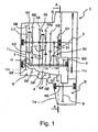
- Figure 1 is a simplified schematic longitudinal cross sectional view, as seen from above, of one example of a variable speed ratio transmission in accordance with a first embodiment of the present invention
- Figure 2 is a simplified schematic transverse cross sectional view as viewed along section line A-A of the transmission in Figure 1;
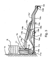
- Figure 3 is a simplified schematic top view of a portion of the transmission 1 for showing the top exterior appearance of an oil gutter of the transmission illustrated in Figures 1 and 2 in accordance with the first embodiment of the present invention
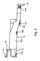
- Figure 4 is a simplified schematic side elevational view of a portion of the transmission 1 for showing the side exterior appearance of the oil gutter 4;
- Figure 5 is an enlarged simplified schematic top view of the downstream edge of the guide path, seen from above;
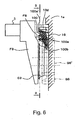
- Figure 6 is a simplified schematic side elevational view of the downstream edge of the guide path as seen from direction of arrow V in Figure 5;
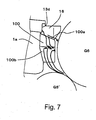
- Figure 7 is a simplified schematic cross sectional view of the downstream edge of the guide path as viewed along section line B-B of Figure 6;
- Figure 8 is a simplified schematic axial end elevational view of a side surface of a shifting fork, as seen from the front side of the transmission in accordance with a second embodiment of the present invention.
- Figure 9 is a simplified schematic cross sectional view as viewed along section line Z-Z of Figure 8 in accordance with the second embodiment of the present invention.
- a variable speed ratio transmission 1 is illustrated cross section with a lubricant supplying structure in accordance with a first embodiment of the present invention.
- the transmission 1 of this first embodiment basically includes an input axle 2 (rotating shaft), an output axle 3 (rotating shaft) and an oil gutter 4 in accordance with the present invention.
- the input axle 2 has a drive gear train G attached thereto.
- the output axle 3 has a driven gear train G' and an output gear GO attached thereto.
- the output gear GO meshes with the drive ring gear R.
- a differential D has a ring gear R that meshes with the output gear GO.
- the oil gutter 4 is attached to a point located at an upper portion of the transmission case 1a above the drive gear train G, the output gear GO and the differential D.
- the oil gutter 4 receives lubricant from the bottom of the case 1a by the rotation of the ring gear R that scoops up lubricant and propels the lubricant into the oil gutter 4.
- the oil gutter 4 is located at a point somewhere between the output axle 3 and a rotating shaft RS of the ring gear R. All of these parts are contained within transmission case 1a.
- the drive gear train G basically includes a 1 st speed drive gear G1, a 2 nd speed drive gear G2, a 3 rd speed drive gear G3, a 4 th speed drive gear G4, a 5 th speed drive gear G5 and a 6 th speed drive gear G6.
- the drive gears G1 to G6 are attached in order from the front edge to the rear edge of transmission case 1a, which is on the clutch side, not shown in the figures.
- the 1 st speed drive gear G1 and the 2 nd speed drive gear G2 are configured as fixed gears, while the 3 rd speed drive gear G3, the 4 th speed drive gear G4, the 5 th speed drive gear G5 and the 6 th speed drive gear G6 are configured as freely rotating gears.
- a 3 rd -4 th speed synchronizer S2 is fixed to the input axle 2 between the 3 rd speed drive gear G 3 and the 4 th speed drive gear G4.
- a 5 th -6 th speed synchronizer S3 is fixed to the input axle 2 between the 5 th speed drive gear G5 and the 6 th speed drive gear G6.
- the 6 th speed drive gear G6 has a 6 th speed clutch gear CG that is embedded in a side surface that faces the 5 th - 6 th speed synchronizer S3.
- the 6 th speed drive gear G6 is a variable speed gear with a clutch gear embedded in its side surface.
- the driven gear train G' basically includes a 1 st speed driven gear G1', a 2 nd speed driven gear G2', a 3rd speed driven gear G3', a 4 th speed driven gear G4', a 5 th speed driven gear G5' and a 6 th speed driven gear G6'.
- the driven gear train G' meshes with the drive gear train G.
- the driven gears G1' to G6' mesh with the drive gears G1 to G6, respectively.
- the driven gears G1' to G6' are attached to the output axle 3 at locations corresponding to the drive gears G1 to G6, respectively, that are attached to the input axle 2.
- the 1 st speed driven gear G1' and the 2 nd speed driven gear G2' are configured as freely rotating gears, while the 3 rd speed driven gear G3', the 4 th speed driven gear G4', the 5 th speed driven gear G5' and the 6 th speed driven gear G6' are configured as fixed gears.
- a 1 st -2 nd speed synchronizer S1 is fixed between the 1 st speed driven gear G1' and the 2 nd speed driven gear G2'.
- the synchronizer S1 includes a coupling sleeve C1 and a shifting fork F1.
- the coupling sleeve C1 is configured and arranged to slide in the axial direction along the output shaft 3 by activation of the shifting fork F1.
- the synchronizer S2 includes a coupling sleeve C2 and a shifting fork F2
- the synchronizer S3 includes a coupling sleeve C3 and a shifting fork F3.
- the coupling sleeve C2 is configured and arranged to slide in the axial direction along the input shaft 2 by activation of the shifting fork F2, while the coupling sleeve C3 is configured and arranged to slide in the axial direction along the input shaft 2 by activation of the shifting fork F3.
- the coupling sleeve C3 has a plurality of splines or teeth (shown in broken lines) formed on an inner peripheral surface.
- the splines or teeth of the coupling sleeve C3 selectively engage a plurality of splines or teeth on the 6 th speed clutch gear CG so that the 6 th speed drive gear G6 selectively rotates with the input shaft 2 when the coupling sleeve C3 is move into engagement with the 6 th speed clutch gear CG by the shifting fork F3.
- the coupling sleeve C3 is disengagement from the 6 th speed clutch gear CG, the 6 th speed clutch gear CG rotates freely about the input shaft 2.
- the synchronizers S1, S2 and S3 have similar structures.
- the differential D is a conventional differential device that transmits power for automatically permitting a variance in the number of rotations of the left and right wheels.
- the differential D is attached to the forward side of transmission case 1a with the ring gear R of the differential D meshing with the output gear GO.
- Figure 3 is a simplified schematic top view of a portion of the transmission 1 for showing the top exterior appearance of the oil gutter 4, while Figure 4 is a simplified schematic side elevational view of the portion of the transmission 1 for showing the side exterior appearance of the oil gutter 4.
- the oil gutter 4 basically has an oil inlet part 11 and an oil channel 12.
- the oil inlet part 11 is configured and arranged relative to the ring gear R to receive the lubricant scooped from the ring gear R.
- the oil channel 12 is configured and arranged relative to the oil inlet part 11 such that the oil channel 12 causes the flow of the received the lubricant to change direction at almost a right angle so as to flow in the axial direction of the transmission 1.
- an oil spill prevention rib 1b is formed at a point located in the upper portion of the transmission case 1a above the oil inlet part 11.
- the oil spill prevention rib 1b is configured to be able to aim the lubricant scooped from the ring gear R at the oil spill prevention rib 1b and guide it to the oil inlet part 11.
- the oil spill prevention rib 1b acts as a guiding member that directs or guides lubricant scooped up due to the rotating of the ring gear R toward the oil gutter 4, without fail.
- the oil inlet part 11 has an outer corner 11a and an inner corner 11b formed where the oil inlet part 11 interconnects with the oil channel 12.
- the oil inlet part 11 also has an oil guide rib 11r extending from the inner corner 11b towards the outer corner 11a.
- the outer corner 11a has an opening 13a acts as a supply port for feeding the lubricant in a direction of an output axle bearing B, which support the output axle 3 for rotation with respect to transmission case 1a.
- the oil guide rib 11r is positioned on the lower wall of the oil inlet part 11 to guide the lubricant from the inner corner 11b to the opening 13a. In other words, the oil guide rib 11r guides the lubricant from the inner corner 11b across the oil channel 12 to the opening 13a.
- the length of the oil guide rib 11r is configured to be about half the length of a diagonal line connecting the outer corner 11a and the inner corner 11b or slightly shorter than length of a diagonal line connecting the outer corner 11a and the inner corner 11b as
- the oil channel 12 has a pair of side wall 12a and 12b for funneling the lubricant from the ring gear R towards the opposite axial end of the transmission 1.
- the oil channel 12 is configured and arranged to become more narrow as the oil channel 12 approaches the 6 th speed drive gear G6 and the 6 th speed driven gear G6' from the 1 st speed drive gear G1 and the 1 st speed driven gear G1'.
- the further downstream oil channel 12 extends, the width of that the oil channel 12 becomes narrower.
- the oil channel 12 is formed at an incline, so that the height and location of its lower surface becomes lower in the downstream direction. In this case, it is possible to increase the flow speed of the lubricant in the downstream direction of the oil channel 12.
- the side wall 12a of the oil channel 12 has an oil opening 13b that faces towards the input axle 2.
- the oil opening 13b acts as a supply port for feeding the lubricant in the direction of the meshing surfaces between the 2 nd speed drive gear G2 and the 2 nd speed driven gear G2', and the meshing surfaces between the 3 rd speed drive gear G3 and the 3 rd speed driven gear G3'.
- the side wall 12a of the oil channel 12 also has with an oil opening 13c that acts as a supply port for feeding the lubricant in the direction of the meshing surfaces between the 4 th speed drive gear G4 and the 4 th speed driven gear G4', and the meshing surfaces between the 5 th speed drive gear G5 and the 5 th speed driven gear G5'.
- the side wall 12a of the oil channel 12 is further provided with an oil opening 13d that faces towards the input axle 2.
- the oil opening 13d acts as a supply port for feeding the lubricant in the direction of the meshing surfaces between the 6 th speed drive gear G6 and the 6 th speed driven gear G6'.
- the oil channel 12 is further provided with a pair of guide walls 14a and 14b for guiding the lubricant along the lower wall of the oil channel 12 to each of the openings 13b, 13c and 13d.
- the guide wall 14a is attached to the near side of the side wall 12a of the oil channel 12.
- the guide wall 14a and the side wall 12a form a guide path 15a for guiding the lubricant to the oil opening 13b.
- the guide wall 14b is attached to the side wall 12b, which is on the opposite side of the side wall 12a of the oil channel 12.
- the guide walls 14a and 14b form a guide path 15b for guiding the lubricant to the oil opening 13d.
- the guide wall 14b and the side wall 12b form a guide path 15c for guiding the lubricant to the oil opening 13c.
- the two guide walls 14a and 14b divide the oil channel 12 into three channels (i.e., the paths 15a to 15c).
- the oil channel 12 has a communicating part 15c' formed on its lower wall, passing below the lower part of guide path 15b and connected to the oil opening 13c in the side wall 12a.
- the communicating part 15c' fluidly connects the guide path 15c to the oil opening 13c.
- the oil channel 12 is configured so that it is possible for the lubricant that flows along the guide path 15c, which is formed in this way on the near side of the side wall 12b, and then to be guided to the oil opening 13c, which is formed on the side wall 12a.
- the oil channel 12 has a protrusion 16 formed at its end that is opposite to the oil inlet part 11.
- This protrusion 16 extends from the side wall 12a at the downstream edge of the guide path 15b where the oil opening 13d is formed.
- the protrusion 16 protrudes at a right angle to the axial direction of the transmission 1.
- the oil inlet part 11, the oil channel 12 and the protrusion 16 are formed as a single unit.
- Figure 5 is an enlarged simplified schematic top view showing the downstream edge of the guide path 15c as elevational viewed from above, while Figure 6 is a side elevational view of the downstream edge of the guide path as seen from direction of arrow V in Figure 5.
- Figure 7 is a simplified schematic cross sectional view of the downstream edge of the guide path as viewed along section line B-B of Figure 6.
- the protrusion 16 is attached to the transmission case 1a by an oil diverting part 100.
- the oil diverting part 100 extends from the transmission case 1a to a location adjacent to the meshing surfaces of the 6 th speed drive gear G6 and the 6 th speed driven gear G6'.
- the protrusion 16 is configured so that a portion of the lubricant fed from the opening 13d is deflected in a smooth curve toward a side surface FS side of the shifting fork F3.
- the lubricant deflected toward the side surface FS of the shifting fork F3 by the protrusion 16 hits the side surface FS of the shifting fork F3, and then streams down the side surface FS.
- the coupling sleeve C3 includes a tapered section (outer corner surface) having a smooth curve with a radius that becomes smaller as the coupling sleeve C3 approaches an end portion of the outer peripheral surface of the coupling sleeve C3 that faces the clutch gear CG.
- the oil diverting part 100 has a first inclined portion with an inclined surface 100a and a second inclined portion with an inclined surface 100b.
- the protrusion 16 constitutes a first orientation or diverting member that is next to the inclined surface 100a, while the second inclined portion with an inclined surface 100b constitutes a second orientation or diverting member.
- the inclined surface 100a is formed so that it is possible to make the lubricant, which is fed from the opening 13d, rapidly flow downward to the meshing surface of the 6 th speed drive gear G6 and the 6 th speed driven gear G6'.
- the inclined surface 100b of the second orientation or diverting member acts as a guiding member that directs or guides lubricant scooped up due to the rotating of the variable speed gear G6 toward the side surface of the shifting fork FS such that the lubrication of the 6 th speed clutch gear CG is further improved.
- the protrusion 16 of the oil channel 12 is preferably attached to the first inclined portion with the inclined surface 100a, while the second inclined portion with the inclined, surface 100b is preferably a part of the wall of the transmission case 1a.
- the inclined surface 100a extends downwardly so as to direct the lubricant from the oil channel 12 towards the meshing surface of the 6 th speed drive gear G6 and the 6 th speed driven gear G6', while the inclined surface 100b so as to direct the lubricant from the rotation of the variable speed gear G6 towards the side surface of the shifting fork FS.
- the inclined surface 100b extends from the inclined surface 100a so as to be vertically and horizontally inclined with respect to a horizontal plane for directing the lubricant against the side surface FS of the shifting fork F3.
- the inclined surface 100b is also formed so that the lubricant that splashes from the meshing surfaces of the 6 th speed drive gear G6 and the 6 th speed driven gear G6' is oriented toward the side surface FS of the shifting fork F3.
- the inclined surface 100a is formed so that it is possible to make the lubricant, which is fed from the oil opening 13d, flow rapidly downward towards the meshing surface of the 6 th speed drive gear G6 and the 6 th speed driven gear G6', while the inclined surface 100a is formed so that it is possible to make the lubricant, which is splashed up from the meshing surfaces of the 6 th speed drive gear G6 and the 6 th speed driven gear G6', flow upwardly towards the side surface FS of the shifting fork F3.
- the lubricant that is oriented toward the side surface FS of the shifting fork F3 by the inclined surface 100b assists the lubricant that is oriented toward side surface FS of the shifting fork F3 by the protrusion 16, and the lubricant that spills from edge surface 100a' of side surface FS of the shifting fork F3 of the inclined surface 100a in reaching side surface FS of the shifting fork F3.
- the lubricant is scooped up from the bottom area of the transmission 1 by the rotation of the ring gear R of the differential D.
- the rotation of the ring gear R conveys the lubricant to the oil inlet part 11 of the oil gutter 4.
- the lubricant on the ring gear R is propelled by the rotation of the ring gear R to hit the oil spill prevention rib 1b.
- a part of the lubricant that is received in the oil inlet part 11 is directed to the oil opening 13a by the guide rib 11r.
- the lubricant exiting from the oil opening 13a is supplied to the bearing B, which supports one end of the output axle 3 to rotate in the transmission case 1a.
- the remaining the lubricant flows into the oil channel 12 and then directed into the oil opening 13b, 13c and 13d by the guide paths 15a, 15b and 15c.
- the lubricant fed from the oil opening 13b is supplied to the meshing surfaces between the 2 nd speed drive gear G2 and the 2 nd speed driven gear G2' and the meshing surfaces between the 3 rd speed drive gear G3 and the 3 rd speed driven gear G3'.
- the lubricant fed from the oil opening 13c is supplied to the meshing surfaces between the 4 th speed drive gear G4 and the 4 th speed driven gear G4', and the meshing surfaces between the 5 th speed drive gear G5 and the 5 th speed driven gear G5'.
- the lubricant fed from opening 13d is supplied to the meshing surfaces between the 6 th speed drive gear G6 and the 6 th speed driven gear G6' by the inclined surface 100a, along with which, a part of the lubricant is directed to the side surface FS of the shifting fork F3 by the protrusion 16.
- the part of the lubricant that is directed by the protrusion 16 to the side surface FS of the shifting fork F3 hits the side surface FS, and then streams down on the outer corner surface of the coupling sleeve C3.
- the lubricant then flows from the outer corner surface of the coupling sleeve C3 to the 6 th speed clutch gear CG, which is embedded in the side surface of the 6 th speed drive gear G6.
- the lubricant at the meshing surfaces between the 6 th speed drive gear G6 and the 6 th speed driven gear G6' splashes against the inclined surface 100b where the lubricant is then directed to the side surface FS of the shifting fork F3.
- This arrangement assists the lubricant that is oriented toward the side surface FS of the shifting fork F3 by the protrusion 16, and the lubricant that spills from the edge surface 100a' of the side surface FS of the shifting fork F3 of the inclined surface 100a in reaching the side surface FS of the shifting fork F3. Accordingly, the lubricant is able to be efficiently supplied to the 6 th speed clutch gear CG.
- the transmission 1 of the first embodiment since a part of the lubricant fed from the oil opening 13d by the protrusion 16, which is formed in the oil gutter 4, is directed to the side surface FS of the shifting fork F3 and hits the side surface FS, and the lubricant that hits it is made to flow from the outer corner surface of the coupling sleeve C3 into the 6 th speed clutch gear CG through the side surface FS, it is possible to ensure more definitely that the lubricant is supplied to the 6 th speed clutch gear CG, which is embedded in side surface of the 6 th speed drive gear G6. Additionally, the lubricant that flows down through the inclined surface 100a without contacting the protrusion 16 is supplied to the meshing surfaces the 6 th speed drive gear G6 and the 6 th speed driven gear G6'.
- the lubricant splashed from the meshing surfaces between the 6 th speed drive gear G6 and the 6 th speed driven gear G6' is directed to the side surface FS of the shifting fork F3 by the inclined surface 100b of the oil diverting part 100, which is formed in transmission case 1a, and assists the lubricant that is oriented toward side surface FS of the shifting fork F3 by protrusion 16, and the lubricant that spills from edge surface 100a' of side surface FS of the shifting fork F3 of the inclined surface 100a in reaching side surface FS of the shifting fork F3, the lubricant is able to be efficiently supplied to the 6 th speed clutch gear CG.
- the lubricant is only oriented to the side surface FS of the shifting fork F3 by using the protrusion 16, it is easier to maintain lubrication of the 6 th speed drive gear G6, which is embedded in the side surface of the 6 th speed clutch gear CG.
- the lubricant is supplied to the clutch gear CG using the side surface of the shifting fork F3 and the coupling sleeve C3 on the clutch gear side of the shifting fork F3, even if the clutch gear CG is embedded in the side surface of the variable speed gear G6, it is possible to supply, without fail, the lubricant to the clutch gear CG via the side surface of the shifting fork F3 and the coupling sleeve C3.
- the lubricant supplying structure to lubricate the clutch gear CG, using a part of the lubricant that lubricates the meshing surfaces of the variable speed gear G6.
- the shifting fork F3 of the transmission 1 of the first embodiment has been replaced with a shifting fork F30 in accordance with a second embodiment.
- the transmission of the second embodiment comprises the same hardware as transmission 1 in the first embodiment, except for changing the shifting fork F3 to the shifting fork F30.
- the parts of the second embodiment that are identical to the parts of the first embodiment will be given the same reference numerals as the parts of the first embodiment.
- the descriptions of the parts of the second embodiment that are identical to the parts of the first embodiment have been omitted for the sake of brevity.
- the parts of the second embodiment that differ from the parts of the first embodiment will be indicated with a single prime (').
- Figure 8 a simplified schematic axial end elevational view of a side surface of a shifting fork, as seen from the front side of the transmission, while simplified schematic cross sectional view as viewed along section line Z-Z of Figure 8.
- the oil gutter 4 and the oil diverting part 100 directs a portion of the lubricant so that the lubricant hits the side surface FS' of the shifting fork F30.
- the side surface FS' of the shifting fork F30 is provides with a plurality of lubricant conduits or guide ways 20 that are configured and arranged to guide the lubricant to the 6 th speed clutch gear CG via the coupling sleeve C3.
- the lubricant conduits 20 are inclined in a direction to direct the lubricant toward the 6 th speed clutch gear CG.
- the lubricant is scooped up from the bottom area of the transmission 1 by the rotation of the ring gear R of the differential D.
- the rotation of the ring gear R conveys the lubricant to the oil inlet part 11 of the oil gutter 4.
- the lubricant on the ring gear R is propelled by the rotation of the ring gear R to hit the oil spill prevention rib 1b.
- a part of the lubricant that is received in the oil inlet part 11 is directed to the oil opening 13a by the guide rib 11r.
- the lubricant exiting from the oil opening 13a is supplied to the bearing B, which supports one end of the output axle 3 to rotate in the transmission case 1a.
- the remaining the lubricant flows into the oil channel 12 and then directed into the oil opening 13b, 13c and 13d by the guide paths 15a, 15b and 15c.
- the lubricant fed from the oil opening 13b is supplied to the meshing surfaces between the 2 nd speed drive gear G2 and the 2 nd speed driven gear G2' and the meshing surfaces between the 3 rd speed drive gear G3 and the 3 rd speed driven gear G3'.
- the lubricant fed from the oil opening 13c is supplied to the meshing surfaces between the 4 th speed drive gear G4 and the 4 th speed driven gear G4', and the meshing surfaces between the 5 th speed drive gear G5 and the 5 th speed driven gear G5'.
- the lubricant fed from opening 13d is supplied to the meshing surfaces between the 6 th speed drive gear G6 and the 6 th speed driven gear G6' by the inclined surface 100a, along with which, a part of the lubricant is directed to the side surface FS' of the shifting fork F30 by the protrusion 16.
- the lubricant hits the side surface FS' that is oriented toward the 6 th speed clutch gear CG, which is embedded in the side surface of the 6 th speed drive gear G6.
- the lubricant that is directed by the protrusion 16 against the side surface FS' of the shifting fork F30 hits the side surface FS', and then streams down the lubricant conduits 20 onto the outer corner surface of the coupling sleeve C3.
- the lubricant then flows from the outer corner surface of the coupling sleeve C3 to the 6 th speed clutch gear CG, which is embedded in the side surface of the 6 th speed drive gear G6.
- the lubricant conduits 20 the lubricant is successfully supplied to the 6 th speed clutch gear CG.
- the lubricant at the meshing surfaces between the 6 th speed drive gear G6 and the 6 th speed driven gear G6' splashes against the inclined surface 100b where the lubricant is then directed to the side surface FS' of the shifting fork F30.
- This arrangement assists the lubricant that is oriented toward the side surface FS' of the shifting fork F30 by the protrusion 16, and the lubricant that spills from the edge surface 100a' of the side surface FS' of the shifting fork F30 of the inclined surface 100a in reaching the side surface FS' of the shifting fork F30. Accordingly, the lubricant is able to be efficiently supplied to the 6 th speed clutch gear CG.
- the lubricant conduits 20 it is possible to supply the lubricant successfully to the 6 th speed clutch gear CG by the lubricant conduits 20, which are formed on the side surface FS' of the 6 th speed of the shifting fork F30.
- the lubricant conduits 20 it is also possible for the lubricant conduits 20 to be formed on an incline so as to orient the lubricant toward the clutch gear side. In this case, it is possible to ensure more definitely that the clutch gear CG will be supplied with the lubricant supplied to the side surface of the shifting fork F30.
- the lubricant oriented toward the side surface FS or FS' of the shifting fork F3 or F30 using the inclined surface 100b of the oil diverting part 100, which is formed in the transmission case 1a the lubricant oriented toward the side surface FS or FS' of the shifting fork F3 or F30 by the protrusion 16 and the lubricant spilling out from the edge surface 100a' of the side surface FS or FS' of the shifting fork F3 or F30 on the inclined surface 100a, is supplied to the side surface FS or FS' of the shifting fork F3 or F30.
- the protrusion 16 is formed as an integral unit with the oil gutter 4
- the lubricant splashed on the meshing surfaces between the 6 th speed drive gear G6 and the 6 th speed driven gear G6' is oriented toward the side surface FS or FS' of the shifting fork F3 or F30 by the inclined surface 100b of the oil diverting part 100, which is formed as a unit in the transmission case 1a, but it is desirable to orient the lubricant splashed on the meshing surfaces the 6 th speed drive gear G6 and the 6 th speed driven gear G6' to the side surface FS or FS' of the shifting fork F3 or F30.
- the 6 th speed clutch gear CG is embedded in the side surface of the 6 th speed drive gear G6 and the protrusion 16 is positioned at the oil opening 13d in order to supply the lubricant to the 6 th speed clutch gear CG.
- the clutch gear is embedded in the side surface of one of the other drive gears (G1, G2, G3, G4, G5), then an oil opening and a protrusion can be provided in the oil channel to supply the lubricant to the meshing surfaces of the corresponding drive gear (G1, G2, G3, G4, G5) and the corresponding driven gear (G1', G2', G3', G4', G5') so that the embedded clutch gear is lubricated.
- the 6 th speed drive gear G6 is a freely rotating gear, but it can be desirable to make the 6 th speed driven gear G6' a freely rotating gear. In this case, it should be configured so that the lubricant fed from the opening will supply the lubricant to the clutch gear embedded in the side surface of the driven gear G6' as a freely rotating gear, by forming a protrusion or incline member so as to direct lubricant to the shifting fork that operates the 6 th speed driven gear G6'.
Landscapes
- Engineering & Computer Science (AREA)
- General Engineering & Computer Science (AREA)
- Mechanical Engineering (AREA)
- General Details Of Gearings (AREA)
- Mechanical Operated Clutches (AREA)
Abstract
Description
- This application claims priority to
Japanese Patent Application No. 2006-021558, filed on January 30, 2006 Japanese Patent Application No. 2006-021558 - The present invention relates to a transmission. More specifically, the present invention relates to a transmission in which a clutch gear is disposed in such a way as to be embedded in a side surface of a variable speed gear that rotates freely on a rotating shaft.
- Various types of transmissions are presently known. One example of a conventional variable speed transmission is disclosed in
Japanese Unexamined Patent Application Publication No. 3035997 - In view of the above, it will be apparent to those skilled in the art from this disclosure that there exists a need for an improved transmission. This invention addresses this need in the art as well as other needs, which will become apparent to those skilled in the art from this disclosure.
- Incidentally, it has been determined that with such a transmission, in order to perform lubrication of parts requiring lubrication, such as the meshing surfaces between the variable speed gears and the meshing surfaces between the coupling sleeve and the clutch gear, there is a need to supply the lubricant. As a structure for supplying the lubricant to these parts requiring lubrication, feeding from an oil gutter is widely known, but when the coupling sleeve and the clutch gear are meshed in the transmission, if one simply feeds from an oil gutter, on certain occasions it may not be possible to supply sufficient lubricant to the clutch gear.
- One of the aims of the transmission of the present invention is to consistently supply lubricant to the clutch gear in a transmission where the clutch gear is embedded in the side surface of a variable speed gear. Furthermore, another of the aims of transmission of the present invention is to supply lubricant to the meshing surfaces of the variable speed gears. Additionally, another of the aims of transmission of the present invention is to more simply maintain the lubricity of the clutch gear embedded in the side surface of the variable speed gear.
- In accordance with one aspect of the present invention, a transmission is provided that basically comprises a rotating shaft, a coupling sleeve, a variable speed gear, a clutch gear, a shifting fork and a lubricant supplying structure. The coupling sleeve is fixedly coupled to the rotating shaft to rotate with the rotating shaft. The variable speed gear is mounted on the rotating shaft to selectively rotate on the rotating shaft. The clutch gear is embedded in a side surface of the variable speed gear to selectively engage the coupling sleeve. The shifting fork is operatively engagable with an outer peripheral area of the coupling sleeve to move the coupling sleeve in an axial direction of the rotating shaft to selectively engage the coupling sleeve with the clutch gear. The lubricant supplying structure is configured and arranged to direct lubricant to the clutch gear by diverting the lubricant against a side surface of the shifting fork that faces the clutch gear and the coupling sleeve.
- These and other objects, features, aspects and advantages of the present invention will become apparent to those skilled in the art from the following detailed description, which, taken in conjunction with the annexed drawings, discloses a preferred embodiment of the present invention.
- Referring now to the attached drawings which form a part of this original disclosure:
- Figure 1 is a simplified schematic longitudinal cross sectional view, as seen from above, of one example of a variable speed ratio transmission in accordance with a first embodiment of the present invention;
- Figure 2 is a simplified schematic transverse cross sectional view as viewed along section line A-A of the transmission in Figure 1;
- Figure 3 is a simplified schematic top view of a portion of the
transmission 1 for showing the top exterior appearance of an oil gutter of the transmission illustrated in Figures 1 and 2 in accordance with the first embodiment of the present invention; - Figure 4 is a simplified schematic side elevational view of a portion of the
transmission 1 for showing the side exterior appearance of theoil gutter 4; - Figure 5 is an enlarged simplified schematic top view of the downstream edge of the guide path, seen from above;
- Figure 6 is a simplified schematic side elevational view of the downstream edge of the guide path as seen from direction of arrow V in Figure 5;
- Figure 7 is a simplified schematic cross sectional view of the downstream edge of the guide path as viewed along section line B-B of Figure 6;
- Figure 8 is a simplified schematic axial end elevational view of a side surface of a shifting fork, as seen from the front side of the transmission in accordance with a second embodiment of the present invention; and
- Figure 9 is a simplified schematic cross sectional view as viewed along section line Z-Z of Figure 8 in accordance with the second embodiment of the present invention.
- Selected embodiments of the present invention will now be explained with reference to the drawings. It will be apparent to those skilled in the art from this disclosure that the following descriptions of the embodiments of the present invention are provided for illustration only and not for the purpose of limiting the invention as defined by the appended claims and their equivalents.
- Referring initially to Figure 1, a variable
speed ratio transmission 1 is illustrated cross section with a lubricant supplying structure in accordance with a first embodiment of the present invention. As shown in Figures 1 and 2, thetransmission 1 of this first embodiment basically includes an input axle 2 (rotating shaft), an output axle 3 (rotating shaft) and anoil gutter 4 in accordance with the present invention. Theinput axle 2 has a drive gear train G attached thereto. Theoutput axle 3 has a driven gear train G' and an output gear GO attached thereto. The output gear GO meshes with the drive ring gear R. A differential D has a ring gear R that meshes with the output gear GO. Theoil gutter 4 is attached to a point located at an upper portion of thetransmission case 1a above the drive gear train G, the output gear GO and the differential D. Theoil gutter 4 receives lubricant from the bottom of thecase 1a by the rotation of the ring gear R that scoops up lubricant and propels the lubricant into theoil gutter 4. Preferably, as viewed from a top view in Figure 1, theoil gutter 4 is located at a point somewhere between theoutput axle 3 and a rotating shaft RS of the ring gear R. All of these parts are contained withintransmission case 1a. - The drive gear train G basically includes a 1st speed drive gear G1, a 2nd speed drive gear G2, a 3rd speed drive gear G3, a 4th speed drive gear G4, a 5th speed drive gear G5 and a 6th speed drive gear G6. The drive gears G1 to G6 are attached in order from the front edge to the rear edge of
transmission case 1a, which is on the clutch side, not shown in the figures. The 1st speed drive gear G1 and the 2nd speed drive gear G2 are configured as fixed gears, while the 3rd speed drive gear G3, the 4th speed drive gear G4, the 5th speed drive gear G5 and the 6th speed drive gear G6 are configured as freely rotating gears. Also, a 3rd-4th speed synchronizer S2 is fixed to theinput axle 2 between the 3rd speed drive gear G3 and the 4th speed drive gear G4. A 5th -6th speed synchronizer S3 is fixed to theinput axle 2 between the 5th speed drive gear G5 and the 6th speed drive gear G6. The 6th speed drive gear G6 has a 6th speed clutch gear CG that is embedded in a side surface that faces the 5th - 6th speed synchronizer S3. Thus, the 6th speed drive gear G6 is a variable speed gear with a clutch gear embedded in its side surface. - Referring now to the
output axle 3, the output gear GO is fixed to a foremost part of theoutput axle 3, which is the clutch side not shown in the figures. The driven gear train G' basically includes a 1st speed driven gear G1', a 2nd speed driven gear G2', a 3rd speed driven gear G3', a 4th speed driven gear G4', a 5th speed driven gear G5' and a 6th speed driven gear G6'. The driven gear train G' meshes with the drive gear train G. In particular, the driven gears G1' to G6' mesh with the drive gears G1 to G6, respectively. Thus, the driven gears G1' to G6' are attached to theoutput axle 3 at locations corresponding to the drive gears G1 to G6, respectively, that are attached to theinput axle 2. The 1st speed driven gear G1' and the 2nd speed driven gear G2' are configured as freely rotating gears, while the 3rd speed driven gear G3', the 4th speed driven gear G4', the 5th speed driven gear G5' and the 6th speed driven gear G6' are configured as fixed gears. Also, a 1st-2nd speed synchronizer S1 is fixed between the 1st speed driven gear G1' and the 2nd speed driven gear G2'. - The synchronizer S1 includes a coupling sleeve C1 and a shifting fork F1. The coupling sleeve C1 is configured and arranged to slide in the axial direction along the
output shaft 3 by activation of the shifting fork F1. Similarly, the synchronizer S2 includes a coupling sleeve C2 and a shifting fork F2, and the synchronizer S3 includes a coupling sleeve C3 and a shifting fork F3. The coupling sleeve C2 is configured and arranged to slide in the axial direction along theinput shaft 2 by activation of the shifting fork F2, while the coupling sleeve C3 is configured and arranged to slide in the axial direction along theinput shaft 2 by activation of the shifting fork F3. As illustrated in Figure 5, the coupling sleeve C3 has a plurality of splines or teeth (shown in broken lines) formed on an inner peripheral surface. The splines or teeth of the coupling sleeve C3 selectively engage a plurality of splines or teeth on the 6th speed clutch gear CG so that the 6th speed drive gear G6 selectively rotates with theinput shaft 2 when the coupling sleeve C3 is move into engagement with the 6th speed clutch gear CG by the shifting fork F3. When the coupling sleeve C3 is disengagement from the 6th speed clutch gear CG, the 6th speed clutch gear CG rotates freely about theinput shaft 2. The synchronizers S1, S2 and S3 have similar structures. - The differential D is a conventional differential device that transmits power for automatically permitting a variance in the number of rotations of the left and right wheels. The differential D is attached to the forward side of
transmission case 1a with the ring gear R of the differential D meshing with the output gear GO. - Figure 3 is a simplified schematic top view of a portion of the
transmission 1 for showing the top exterior appearance of theoil gutter 4, while Figure 4 is a simplified schematic side elevational view of the portion of thetransmission 1 for showing the side exterior appearance of theoil gutter 4. As shown in Figure 3, theoil gutter 4 basically has anoil inlet part 11 and anoil channel 12. Theoil inlet part 11 is configured and arranged relative to the ring gear R to receive the lubricant scooped from the ring gear R. Theoil channel 12 is configured and arranged relative to theoil inlet part 11 such that theoil channel 12 causes the flow of the received the lubricant to change direction at almost a right angle so as to flow in the axial direction of thetransmission 1. - As shown in Figures 3 and 4, an oil
spill prevention rib 1b is formed at a point located in the upper portion of thetransmission case 1a above theoil inlet part 11. The oilspill prevention rib 1b is configured to be able to aim the lubricant scooped from the ring gear R at the oilspill prevention rib 1b and guide it to theoil inlet part 11. Thus., the oilspill prevention rib 1b acts as a guiding member that directs or guides lubricant scooped up due to the rotating of the ring gear R toward theoil gutter 4, without fail. - The
oil inlet part 11 has anouter corner 11a and aninner corner 11b formed where theoil inlet part 11 interconnects with theoil channel 12. Theoil inlet part 11 also has anoil guide rib 11r extending from theinner corner 11b towards theouter corner 11a. Theouter corner 11a has anopening 13a acts as a supply port for feeding the lubricant in a direction of an output axle bearing B, which support theoutput axle 3 for rotation with respect totransmission case 1a. Theoil guide rib 11r is positioned on the lower wall of theoil inlet part 11 to guide the lubricant from theinner corner 11b to theopening 13a. In other words, theoil guide rib 11r guides the lubricant from theinner corner 11b across theoil channel 12 to theopening 13a. The length of theoil guide rib 11r is configured to be about half the length of a diagonal line connecting theouter corner 11a and theinner corner 11b or slightly shorter than length of a diagonal line connecting theouter corner 11a and theinner corner 11b as shown in Figure 3. - The
oil channel 12 has a pair ofside wall transmission 1. In particular, theoil channel 12 is configured and arranged to become more narrow as theoil channel 12 approaches the 6th speed drive gear G6 and the 6th speed driven gear G6' from the 1st speed drive gear G1 and the 1st speed driven gear G1'. In other words, the furtherdownstream oil channel 12 extends, the width of that theoil channel 12 becomes narrower. Moreover, theoil channel 12 is formed at an incline, so that the height and location of its lower surface becomes lower in the downstream direction. In this case, it is possible to increase the flow speed of the lubricant in the downstream direction of theoil channel 12. As a result, it is possible to supply the lubricant, without fail, as far as the downstream point in theoil gutter 4. Theside wall 12a of theoil channel 12 has anoil opening 13b that faces towards theinput axle 2. Theoil opening 13b acts as a supply port for feeding the lubricant in the direction of the meshing surfaces between the 2nd speed drive gear G2 and the 2nd speed driven gear G2', and the meshing surfaces between the 3rd speed drive gear G3 and the 3rd speed driven gear G3'. Theside wall 12a of theoil channel 12 also has with anoil opening 13c that acts as a supply port for feeding the lubricant in the direction of the meshing surfaces between the 4th speed drive gear G4 and the 4th speed driven gear G4', and the meshing surfaces between the 5th speed drive gear G5 and the 5th speed driven gear G5'. Theside wall 12a of theoil channel 12 is further provided with anoil opening 13d that faces towards theinput axle 2. Theoil opening 13d acts as a supply port for feeding the lubricant in the direction of the meshing surfaces between the 6th speed drive gear G6 and the 6th speed driven gear G6'. Theoil channel 12 is further provided with a pair ofguide walls oil channel 12 to each of theopenings - The
guide wall 14a is attached to the near side of theside wall 12a of theoil channel 12. Theguide wall 14a and theside wall 12a form aguide path 15a for guiding the lubricant to theoil opening 13b. Theguide wall 14b is attached to theside wall 12b, which is on the opposite side of theside wall 12a of theoil channel 12. Theguide walls guide path 15b for guiding the lubricant to theoil opening 13d. Theguide wall 14b and theside wall 12b form aguide path 15c for guiding the lubricant to theoil opening 13c. In other words, the twoguide walls oil channel 12 into three channels (i.e., thepaths 15a to 15c). - The
oil channel 12 has a communicatingpart 15c' formed on its lower wall, passing below the lower part ofguide path 15b and connected to theoil opening 13c in theside wall 12a. Thus, the communicatingpart 15c' fluidly connects theguide path 15c to theoil opening 13c. In other words, theoil channel 12 is configured so that it is possible for the lubricant that flows along theguide path 15c, which is formed in this way on the near side of theside wall 12b, and then to be guided to theoil opening 13c, which is formed on theside wall 12a. Also, theoil channel 12 has aprotrusion 16 formed at its end that is opposite to theoil inlet part 11. Thisprotrusion 16 extends from theside wall 12a at the downstream edge of theguide path 15b where theoil opening 13d is formed. Theprotrusion 16 protrudes at a right angle to the axial direction of thetransmission 1. Preferably, theoil inlet part 11, theoil channel 12 and theprotrusion 16 are formed as a single unit. - Figure 5 is an enlarged simplified schematic top view showing the downstream edge of the
guide path 15c as elevational viewed from above, while Figure 6 is a side elevational view of the downstream edge of the guide path as seen from direction of arrow V in Figure 5. Figure 7 is a simplified schematic cross sectional view of the downstream edge of the guide path as viewed along section line B-B of Figure 6. As shown in Figures 5 to 7, theprotrusion 16 is attached to thetransmission case 1a by anoil diverting part 100. Theoil diverting part 100 extends from thetransmission case 1a to a location adjacent to the meshing surfaces of the 6th speed drive gear G6 and the 6th speed driven gear G6'. Theprotrusion 16 is configured so that a portion of the lubricant fed from theopening 13d is deflected in a smooth curve toward a side surface FS side of the shifting fork F3. The lubricant deflected toward the side surface FS of the shifting fork F3 by theprotrusion 16 hits the side surface FS of the shifting fork F3, and then streams down the side surface FS. The lubricant then spills from the side surface FS of the shifting fork F3 onto an outer peripheral area (outer corner surface) of the coupling sleeve C3, where the lubricant streams down from the outer peripheral area (outer corner surface) of the coupling sleeve C3 to direct the lubricant to the 6th speed clutch gear CG that is embedded in the side surface of the 6th speed drive gear G6. As seen in Figure 6, the coupling sleeve C3 includes a tapered section (outer corner surface) having a smooth curve with a radius that becomes smaller as the coupling sleeve C3 approaches an end portion of the outer peripheral surface of the coupling sleeve C3 that faces the clutch gear CG. - As seen in Figures 5 to 7, the
oil diverting part 100 has a first inclined portion with aninclined surface 100a and a second inclined portion with aninclined surface 100b. Theprotrusion 16 constitutes a first orientation or diverting member that is next to theinclined surface 100a, while the second inclined portion with aninclined surface 100b constitutes a second orientation or diverting member. In other words, theinclined surface 100a is formed so that it is possible to make the lubricant, which is fed from theopening 13d, rapidly flow downward to the meshing surface of the 6th speed drive gear G6 and the 6th speed driven gear G6'. Theinclined surface 100b of the second orientation or diverting member acts as a guiding member that directs or guides lubricant scooped up due to the rotating of the variable speed gear G6 toward the side surface of the shifting fork FS such that the lubrication of the 6th speed clutch gear CG is further improved. - The
protrusion 16 of theoil channel 12 is preferably attached to the first inclined portion with theinclined surface 100a, while the second inclined portion with the inclined,surface 100b is preferably a part of the wall of thetransmission case 1a. As best seen in Figure 7, theinclined surface 100a extends downwardly so as to direct the lubricant from theoil channel 12 towards the meshing surface of the 6th speed drive gear G6 and the 6th speed driven gear G6', while theinclined surface 100b so as to direct the lubricant from the rotation of the variable speed gear G6 towards the side surface of the shifting fork FS. In this case it is possible to more efficiently supply the lubricant to the side surface of the shifting fork FS. As a result, it is possible to ensure more definitely that the 6th speed clutch gear CG will be lubricated. - As best seen in Figure 6, the
inclined surface 100b extends from theinclined surface 100a so as to be vertically and horizontally inclined with respect to a horizontal plane for directing the lubricant against the side surface FS of the shifting fork F3. Theinclined surface 100b is also formed so that the lubricant that splashes from the meshing surfaces of the 6th speed drive gear G6 and the 6th speed driven gear G6' is oriented toward the side surface FS of the shifting fork F3. Accordingly, theinclined surface 100a is formed so that it is possible to make the lubricant, which is fed from theoil opening 13d, flow rapidly downward towards the meshing surface of the 6th speed drive gear G6 and the 6th speed driven gear G6', while theinclined surface 100a is formed so that it is possible to make the lubricant, which is splashed up from the meshing surfaces of the 6th speed drive gear G6 and the 6th speed driven gear G6', flow upwardly towards the side surface FS of the shifting fork F3. The lubricant that is oriented toward the side surface FS of the shifting fork F3 by theinclined surface 100b assists the lubricant that is oriented toward side surface FS of the shifting fork F3 by theprotrusion 16, and the lubricant that spills fromedge surface 100a' of side surface FS of the shifting fork F3 of theinclined surface 100a in reaching side surface FS of the shifting fork F3. - Next, the lubricating operation of the lubricant supplying structure of the
transmission 1 of this first embodiment will be explained. In particular, the lubricant flow to the 6th speed clutch gear CG by theoil gutter 4 will now be explained. - The lubricant is scooped up from the bottom area of the
transmission 1 by the rotation of the ring gear R of the differential D. Thus, the rotation of the ring gear R conveys the lubricant to theoil inlet part 11 of theoil gutter 4. For example, the lubricant on the ring gear R is propelled by the rotation of the ring gear R to hit the oilspill prevention rib 1b. Accordingly, a part of the lubricant that is received in theoil inlet part 11 is directed to theoil opening 13a by theguide rib 11r. The lubricant exiting from theoil opening 13a is supplied to the bearing B, which supports one end of theoutput axle 3 to rotate in thetransmission case 1a. The remaining the lubricant flows into theoil channel 12 and then directed into theoil opening guide paths - The lubricant fed from the
oil opening 13b is supplied to the meshing surfaces between the 2nd speed drive gear G2 and the 2nd speed driven gear G2' and the meshing surfaces between the 3rd speed drive gear G3 and the 3rd speed driven gear G3'. The lubricant fed from theoil opening 13c is supplied to the meshing surfaces between the 4th speed drive gear G4 and the 4th speed driven gear G4', and the meshing surfaces between the 5th speed drive gear G5 and the 5th speed driven gear G5'. - The lubricant fed from opening 13d is supplied to the meshing surfaces between the 6th speed drive gear G6 and the 6th speed driven gear G6' by the
inclined surface 100a, along with which, a part of the lubricant is directed to the side surface FS of the shifting fork F3 by theprotrusion 16. In particular, the part of the lubricant that is directed by theprotrusion 16 to the side surface FS of the shifting fork F3 hits the side surface FS, and then streams down on the outer corner surface of the coupling sleeve C3. The lubricant then flows from the outer corner surface of the coupling sleeve C3 to the 6th speed clutch gear CG, which is embedded in the side surface of the 6th speed drive gear G6. At this time, some of the lubricant at the meshing surfaces between the 6th speed drive gear G6 and the 6th speed driven gear G6' splashes against theinclined surface 100b where the lubricant is then directed to the side surface FS of the shifting fork F3. This arrangement assists the lubricant that is oriented toward the side surface FS of the shifting fork F3 by theprotrusion 16, and the lubricant that spills from theedge surface 100a' of the side surface FS of the shifting fork F3 of theinclined surface 100a in reaching the side surface FS of the shifting fork F3. Accordingly, the lubricant is able to be efficiently supplied to the 6th speed clutch gear CG. - According to the
transmission 1 of the first embodiment, as explained above, since a part of the lubricant fed from theoil opening 13d by theprotrusion 16, which is formed in theoil gutter 4, is directed to the side surface FS of the shifting fork F3 and hits the side surface FS, and the lubricant that hits it is made to flow from the outer corner surface of the coupling sleeve C3 into the 6th speed clutch gear CG through the side surface FS, it is possible to ensure more definitely that the lubricant is supplied to the 6th speed clutch gear CG, which is embedded in side surface of the 6th speed drive gear G6. Additionally, the lubricant that flows down through theinclined surface 100a without contacting theprotrusion 16 is supplied to the meshing surfaces the 6th speed drive gear G6 and the 6th speed driven gear G6'. - Also, according to the
transmission 1 of the first embodiment, because the lubricant splashed from the meshing surfaces between the 6th speed drive gear G6 and the 6th speed driven gear G6' is directed to the side surface FS of the shifting fork F3 by theinclined surface 100b of theoil diverting part 100, which is formed intransmission case 1a, and assists the lubricant that is oriented toward side surface FS of the shifting fork F3 byprotrusion 16, and the lubricant that spills fromedge surface 100a' of side surface FS of the shifting fork F3 of theinclined surface 100a in reaching side surface FS of the shifting fork F3, the lubricant is able to be efficiently supplied to the 6th speed clutch gear CG. - Furthermore, according to the
transmission 1 in the first embodiment, because the lubricant is only oriented to the side surface FS of the shifting fork F3 by using theprotrusion 16, it is easier to maintain lubrication of the 6th speed drive gear G6, which is embedded in the side surface of the 6th speed clutch gear CG. - With the
transmission 1 of the present invention, since the lubricant is supplied to the clutch gear CG using the side surface of the shifting fork F3 and the coupling sleeve C3 on the clutch gear side of the shifting fork F3, even if the clutch gear CG is embedded in the side surface of the variable speed gear G6, it is possible to supply, without fail, the lubricant to the clutch gear CG via the side surface of the shifting fork F3 and the coupling sleeve C3. Moreover, with such a transmission as the one in the present invention,-it is possible for the lubricant supplying structure to lubricate the clutch gear CG, using a part of the lubricant that lubricates the meshing surfaces of the variable speed gear G6. - Referring now to Figures 8 and 9, the shifting fork F3 of the
transmission 1 of the first embodiment has been replaced with a shifting fork F30 in accordance with a second embodiment. In other words, the transmission of the second embodiment comprises the same hardware astransmission 1 in the first embodiment, except for changing the shifting fork F3 to the shifting fork F30. In view of the similarity between the first and second embodiments, the parts of the second embodiment that are identical to the parts of the first embodiment will be given the same reference numerals as the parts of the first embodiment. Moreover, the descriptions of the parts of the second embodiment that are identical to the parts of the first embodiment have been omitted for the sake of brevity. The parts of the second embodiment that differ from the parts of the first embodiment will be indicated with a single prime ('). - Figure 8 a simplified schematic axial end elevational view of a side surface of a shifting fork, as seen from the front side of the transmission, while simplified schematic cross sectional view as viewed along section line Z-Z of Figure 8. As in the first embodiment, the
oil gutter 4 and theoil diverting part 100 directs a portion of the lubricant so that the lubricant hits the side surface FS' of the shifting fork F30. The side surface FS' of the shifting fork F30 is provides with a plurality of lubricant conduits or guideways 20 that are configured and arranged to guide the lubricant to the 6th speed clutch gear CG via the coupling sleeve C3. Thelubricant conduits 20 are inclined in a direction to direct the lubricant toward the 6th speed clutch gear CG. - Next, the lubricating operation of the lubricant supplying structure of the
transmission 1 of this second embodiment will be explained. In particular, the lubricant flow to the 6th speed clutch gear CG by theoil gutter 4 will now be explained. - Similar to the first embodiment, the lubricant is scooped up from the bottom area of the
transmission 1 by the rotation of the ring gear R of the differential D. Thus, the rotation of the ring gear R conveys the lubricant to theoil inlet part 11 of theoil gutter 4. For example, the lubricant on the ring gear R is propelled by the rotation of the ring gear R to hit the oilspill prevention rib 1b. Accordingly, a part of the lubricant that is received in theoil inlet part 11 is directed to theoil opening 13a by theguide rib 11r. The lubricant exiting from theoil opening 13a is supplied to the bearing B, which supports one end of theoutput axle 3 to rotate in thetransmission case 1a. The remaining the lubricant flows into theoil channel 12 and then directed into theoil opening guide paths - The lubricant fed from the
oil opening 13b is supplied to the meshing surfaces between the 2nd speed drive gear G2 and the 2nd speed driven gear G2' and the meshing surfaces between the 3rd speed drive gear G3 and the 3rd speed driven gear G3'. The lubricant fed from theoil opening 13c is supplied to the meshing surfaces between the 4th speed drive gear G4 and the 4th speed driven gear G4', and the meshing surfaces between the 5th speed drive gear G5 and the 5th speed driven gear G5'. - The lubricant fed from opening 13d is supplied to the meshing surfaces between the 6th speed drive gear G6 and the 6th speed driven gear G6' by the
inclined surface 100a, along with which, a part of the lubricant is directed to the side surface FS' of the shifting fork F30 by theprotrusion 16. Thus, the lubricant hits the side surface FS' that is oriented toward the 6th speed clutch gear CG, which is embedded in the side surface of the 6th speed drive gear G6. In particular, the lubricant that is directed by theprotrusion 16 against the side surface FS' of the shifting fork F30 hits the side surface FS', and then streams down thelubricant conduits 20 onto the outer corner surface of the coupling sleeve C3. The lubricant then flows from the outer corner surface of the coupling sleeve C3 to the 6th speed clutch gear CG, which is embedded in the side surface of the 6th speed drive gear G6. By using thelubricant conduits 20, the lubricant is successfully supplied to the 6th speed clutch gear CG. At this time, some of the lubricant at the meshing surfaces between the 6th speed drive gear G6 and the 6th speed driven gear G6' splashes against theinclined surface 100b where the lubricant is then directed to the side surface FS' of the shifting fork F30. This arrangement assists the lubricant that is oriented toward the side surface FS' of the shifting fork F30 by theprotrusion 16, and the lubricant that spills from theedge surface 100a' of the side surface FS' of the shifting fork F30 of theinclined surface 100a in reaching the side surface FS' of the shifting fork F30. Accordingly, the lubricant is able to be efficiently supplied to the 6th speed clutch gear CG. - According to the transmission of the second embodiment, as explained above, operational effects similar to the
transmission 1 of the first embodiment. In other words, it is possible to ensure more definitely that the lubricant is supplied to the 6th speed clutch gear CG, which is embedded in the side surface of the 6th speed drive gear G6. Also the effect of supplying the lubricant to the meshing surfaces of the 6th speed drive gear G6 and the 6th speed driven gear G6', and the effect of supplying the lubricant efficiently to the 6th speed clutch gear CG by using theinclined surface 100b are achieved successfully. In addition, it is possible to supply the lubricant successfully to the 6th speed clutch gear CG by thelubricant conduits 20, which are formed on the side surface FS' of the 6th speed of the shifting fork F30. In other words, in the transmission of the present invention, it is also possible for thelubricant conduits 20 to be formed on an incline so as to orient the lubricant toward the clutch gear side. In this case, it is possible to ensure more definitely that the clutch gear CG will be supplied with the lubricant supplied to the side surface of the shifting fork F30. - In the
transmissions 1 of the first and second embodiments, by directing the lubricant oriented toward the side surface FS or FS' of the shifting fork F3 or F30 using theinclined surface 100b of theoil diverting part 100, which is formed in thetransmission case 1a, the lubricant oriented toward the side surface FS or FS' of the shifting fork F3 or F30 by theprotrusion 16 and the lubricant spilling out from theedge surface 100a' of the side surface FS or FS' of the shifting fork F3 or F30 on theinclined surface 100a, is supplied to the side surface FS or FS' of the shifting fork F3 or F30. However, it can be preferable to supply the lubricant to the side surface FS or FS' of the shifting fork F3 or F30 using only theprotrusion 16 without using theinclined surface 100b of theoil diverting part 100, or to supply the lubricant to the side surface FS or FS' of the shifting fork F3 or F30 using only theinclined surface 100b of theoil diverting part 100. - In the
transmissions 1 of the first and second embodiments, while the lubricant from theoil opening 13d is directed toward the side surface FS or FS' of the shifting fork F3 or F30 by theprotrusion 16, which is formed as an integral unit with theoil gutter 4, it can be desirable to form theprotrusion 16 as a separate unit from theoil gutter 4. Also, it can be preferable to use a part of thetransmission case 1a to direct the lubricant fed from theoil opening 13d to the side surface FS or FS' of the shifting forks F3 and F30. - In the
transmissions 1 of the first and second embodiments, the lubricant splashed on the meshing surfaces between the 6th speed drive gear G6 and the 6th speed driven gear G6' is oriented toward the side surface FS or FS' of the shifting fork F3 or F30 by theinclined surface 100b of theoil diverting part 100, which is formed as a unit in thetransmission case 1a, but it is desirable to orient the lubricant splashed on the meshing surfaces the 6th speed drive gear G6 and the 6th speed driven gear G6' to the side surface FS or FS' of the shifting fork F3 or F30. For example, it can be desirable to direct the lubricant that splashed on the meshing surfaces of the 6th speed drive gear G6 and the 6th speed driven gear G6' to the side surface FS or FS' of the shifting fork F3 or F30 by an orientation board, etc., which is provided separately from thetransmission case 1a. - In the
transmissions 1 of the first and second embodiments, the 6th speed clutch gear CG is embedded in the side surface of the 6th speed drive gear G6 and theprotrusion 16 is positioned at theoil opening 13d in order to supply the lubricant to the 6th speed clutch gear CG. However if the clutch gear is embedded in the side surface of one of the other drive gears (G1, G2, G3, G4, G5), then an oil opening and a protrusion can be provided in the oil channel to supply the lubricant to the meshing surfaces of the corresponding drive gear (G1, G2, G3, G4, G5) and the corresponding driven gear (G1', G2', G3', G4', G5') so that the embedded clutch gear is lubricated. - In the
transmissions 1 of the first and second embodiments, the 6th speed drive gear G6 is a freely rotating gear, but it can be desirable to make the 6th speed driven gear G6' a freely rotating gear. In this case, it should be configured so that the lubricant fed from the opening will supply the lubricant to the clutch gear embedded in the side surface of the driven gear G6' as a freely rotating gear, by forming a protrusion or incline member so as to direct lubricant to the shifting fork that operates the 6th speed driven gear G6'. - In understanding the scope of the present invention, the term "comprising" and its derivatives, as used herein, are intended to be open ended terms that specify the presence of the stated features, elements, components, groups, integers, and/or steps, but do not exclude the presence of other unstated features, elements, components, groups, integers and/or steps. The foregoing also applies to words having similar meanings such as the terms, "including", "having" and their derivatives. Also, the terms "part," "section," "portion," "member" or "element" when used in the singular can have the dual meaning of a single part or a plurality of parts. Also as used herein to describe the above embodiment(s), the following directional terms "forward, rearward, above, downward, vertical, horizontal, below and transverse" as well as any other similar directional terms refer to those directions of a vehicle equipped with the transmission of the present invention. Accordingly, these terms, as utilized to describe the present invention should be interpreted relative to a vehicle equipped with the transmission of the present invention.
- Moreover, terms that are expressed as "means-plus function" in the claims should include any structure that can be utilized to carry out the function of that part of the present invention. The terms of degree such as "substantially", "about" and "approximately" as used herein mean a reasonable amount of deviation of the modified term such that the end result is not significantly changed.
- While only selected embodiments have been chosen to illustrate the present invention, it will be apparent to those skilled in the art from this disclosure that various changes and modifications can be made herein without departing from the scope of the invention as defined in the appended claims. For example, the size, shape, location or orientation of the various components can be changed as needed and/or desired. Components that are shown directly connected or contacting each other can have intermediate structures disposed between them. The functions of one element can be performed by two, and vice versa. The structures and functions of one embodiment can be adopted in another embodiment. It is not necessary for all advantages to be present in a particular embodiment at the same time. Every feature which is unique from the prior art, alone or in combination with other features, also should be considered a separate description of further inventions by the applicant, including the structural and/or functional concepts embodied by such feature(s). Thus, the foregoing descriptions of the embodiments according to the present invention are provided for illustration only, and not for the purpose of limiting the invention as defined by the appended claims and their equivalents.
Claims (15)
- A transmission comprising:a rotating shaft (2);a coupling sleeve (C3) coupled to the rotating shaft (2) to rotate with the rotating shaft (2);a variable speed gear (G6) mounted on the rotating shaft (2) to selectively rotate on the rotating shaft (2);a clutch gear (CG) embedded in a side surface of the variable speed gear (G6) to selectively engage the coupling sleeve (C3);a shifting fork (F3, F30) operatively engagable with an outer peripheral area of the coupling sleeve (C3) to move the coupling sleeve (C3) in an axial direction of the rotating shaft (2) to selectively engage the coupling sleeve (C3) with the clutch gear (CG); anda lubricant supplying structure configured and arranged to direct lubricant to the clutch gear (CG) by diverting the lubricant against a side surface of the shifting fork (F3, F30) that faces the clutch gear (CG) and the coupling sleeve (C3).
- The transmission according to claim 1, wherein
the lubricant supplying structure includes an oil gutter (4) configured and arranged to direct a part of the lubricant, which is supplied to a meshing surface, to the side surface of the shifting fork (F3, F30). - The transmission according to claim 2, wherein
the lubricant supplying structure further includes a first orientation member (16) configured and arranged to direct a part of the lubricant, which is supplied to the meshing surface, to the side surface of the shifting fork (F3, F30). - The transmission according to claim 1 or 2, wherein
the lubricant supplying structure further includes a second orientation member (100b) configured and arranged to direct a part of the lubricant, which is scooped up by rotation of the variable speed gear (G6), to the side surface of the shifting fork (F3, F30). - The transmission according to claim 3, wherein
the lubricant supplying structure further includes a second orientation member (100b) configured and arranged to direct a part of the lubricant, which is scooped up by rotation of the variable speed gear (G6), to the side surface of the shifting fork (F3, F30). - The transmission according to claim 5, wherein
the first and second orientation members (16, 100b) are configured to cooperate together to direct a part of the lubricant to the side surface of the shifting fork (F3, F30). - The transmission according to claim 6, wherein
the first and second orientation members (100b) are configured and arranged relative to each other such that the lubricant directed by the second orientation member (100b) towards the side surface of the shifting fork (F3, F30) aids in directing the lubricant from the first orientation member (16) towards the side surface of the shifting fork (F3, F30). - The transmission according to any one of claims 4 to 7, wherein
the second orientation member (100b) is formed by a part of a transmission case (1a). - The transmission according to any one of claims 2 to 8, wherein
the lubricant supplying structure further includes a guiding member (1b) configured and arranged to direct the lubricant, which is scooped up by rotation of a differential gear, to the oil gutter (4). - The transmission according to any one of claims 2 to 9, wherein
the oil gutter (4) has a channel width that becomes narrower in a downstream direction with respect to the axial direction of the rotating shaft (2). - The transmission according to claim 9, wherein
the guiding member (1b) includes a rib formed by a part of a transmission case (1a). - The transmission according to any one of claims 1 to 11, wherein
the side surface of the shifting fork (F3, F30) includes a lubricant channel (20) configured and arranged to direct a part of the lubricant, which has been directed against the side surface of the shifting fork (F3, F30) by lubricant supplying structure, to the clutch gear (CG). - The transmission according to claim 12, wherein
the lubricant channel (20) is inclined relative to the axial direction of the rotating shaft (2) so as to direct the lubricant along a path toward a side surface of the clutch gear (CG) that faces the side surface of the shifting fork (F3, F30). - The transmission according to any one of claims 1 to 13, wherein
the coupling sleeve (C3) includes a tapered section having a radius that becomes smaller as the tapered section approaches an end portion of the outer peripheral surface of the coupling sleeve (C3), and the end portion faces the clutch gear side.. - The transmission according to any one of claims 1 to 14, wherein
the coupling sleeve (C3) including a spline formed on an inner surface that meshes with the clutch gear (CG).
Applications Claiming Priority (1)
| Application Number | Priority Date | Filing Date | Title |
|---|---|---|---|
| JP2006021558A JP4874661B2 (en) | 2006-01-30 | 2006-01-30 | transmission |
Publications (3)
| Publication Number | Publication Date |
|---|---|
| EP1813838A2 true EP1813838A2 (en) | 2007-08-01 |
| EP1813838A3 EP1813838A3 (en) | 2011-02-23 |
| EP1813838B1 EP1813838B1 (en) | 2012-04-18 |
Family
ID=37964560
Family Applications (1)
| Application Number | Title | Priority Date | Filing Date |
|---|---|---|---|
| EP07001317A Ceased EP1813838B1 (en) | 2006-01-30 | 2007-01-22 | Transmission |
Country Status (5)
| Country | Link |
|---|---|
| US (1) | US8079445B2 (en) |
| EP (1) | EP1813838B1 (en) |
| JP (1) | JP4874661B2 (en) |
| KR (1) | KR101321325B1 (en) |
| CN (1) | CN101012877B (en) |
Cited By (3)
| Publication number | Priority date | Publication date | Assignee | Title |
|---|---|---|---|---|
| EP2148114A1 (en) * | 2008-07-24 | 2010-01-27 | Aichi Machine Industry Co. Ltd. | Lubricating apparatus and transmission equipped with the same |
| CN110206874A (en) * | 2018-02-28 | 2019-09-06 | 丰田自动车株式会社 | Vehicle driving apparatus |
| EP3209907B1 (en) | 2014-10-24 | 2019-12-25 | Magna PT B.V. & Co. KG | Fluid conducting device and motor vehicle transmission |
Families Citing this family (9)
| Publication number | Priority date | Publication date | Assignee | Title |
|---|---|---|---|---|
| JP5360412B2 (en) * | 2009-12-28 | 2013-12-04 | スズキ株式会社 | Transmission lubrication structure |
| JP5113949B1 (en) | 2012-05-09 | 2013-01-09 | 株式会社小松製作所 | Wheel loader |
| JP5867438B2 (en) * | 2013-03-29 | 2016-02-24 | マツダ株式会社 | Transmission lubrication structure |
| JP5966997B2 (en) * | 2013-03-29 | 2016-08-10 | マツダ株式会社 | Transmission lubrication structure |
| MX2017009813A (en) * | 2015-01-29 | 2017-11-02 | Aichi Machine Ind | Oil garter and transmission provided with same. |
| DE102016207456A1 (en) * | 2016-04-29 | 2017-11-02 | Zf Friedrichshafen Ag | Displacement body in a vehicle transmission |
| JP7243472B2 (en) * | 2019-06-12 | 2023-03-22 | トヨタ自動車株式会社 | vehicle power transmission |
| JP7671158B2 (en) * | 2021-03-08 | 2025-05-01 | ニデック株式会社 | Transmission mechanism and drive unit |
| JP2025024591A (en) * | 2023-08-07 | 2025-02-20 | 本田技研工業株式会社 | Power transmission |
Citations (1)
| Publication number | Priority date | Publication date | Assignee | Title |
|---|---|---|---|---|
| JPH0335997B2 (en) | 1987-04-04 | 1991-05-30 | Mitsubishi Genshi Nenryo Kk |
Family Cites Families (24)
| Publication number | Priority date | Publication date | Assignee | Title |
|---|---|---|---|---|
| US2046957A (en) * | 1935-05-18 | 1936-07-07 | Int Motor Co | Synchronizing mechanism |
| US2395189A (en) * | 1940-02-07 | 1946-02-19 | Clark Equipment Co | Synchronizer |
| US3587783A (en) * | 1969-11-28 | 1971-06-28 | Gen Motors Corp | Power transmission and transmission-lubricating system |
| US4242923A (en) * | 1977-11-02 | 1981-01-06 | Toyota Jidosha Kogyo Kabushiki Kaisha | Lubrication in power transmission unit |
| JPS6059864U (en) * | 1983-09-30 | 1985-04-25 | 富士重工業株式会社 | Transmission lubrication system |
| JPS62143859U (en) * | 1986-03-06 | 1987-09-10 | ||
| JPH01128063U (en) * | 1988-02-26 | 1989-08-31 | ||
| JPH0241723U (en) * | 1988-09-14 | 1990-03-22 | ||
| DE3906376A1 (en) | 1989-03-01 | 1990-09-06 | Will E C H Gmbh & Co | Device for slitting moving webs of material |
| JP3035997B2 (en) | 1990-06-30 | 2000-04-24 | スズキ株式会社 | Transmission shifting device |
| JPH0462951U (en) * | 1990-10-04 | 1992-05-28 | ||
| JPH0495352U (en) * | 1991-01-18 | 1992-08-18 | ||
| JPH04277361A (en) * | 1991-02-28 | 1992-10-02 | Suzuki Motor Corp | Lubricating construction in geared transmission |
| IT1245811B (en) * | 1991-05-17 | 1994-10-18 | Fiat Auto Spa | OIL COLLECTOR INSERT FOR LUBRICATION OF A SYNCHRONIZER OF A VEHICLE SPEED CHANGE. |
| JPH0559038U (en) * | 1992-01-20 | 1993-08-03 | マツダ株式会社 | Lubrication structure of transmission |
| JPH061908U (en) * | 1992-06-16 | 1994-01-14 | 日野自動車工業株式会社 | Lubrication device for gear transmission |
| JPH10299876A (en) | 1997-04-25 | 1998-11-13 | Suzuki Motor Corp | Shift fork with lubrication function |
| JPH11118029A (en) | 1997-10-13 | 1999-04-30 | Daihatsu Motor Co Ltd | Lubrication structure of shift fork |
| JP3646498B2 (en) * | 1997-12-26 | 2005-05-11 | スズキ株式会社 | Transmission lubrication device |
| DE19858987A1 (en) * | 1998-12-21 | 2000-06-29 | Schaeffler Waelzlager Ohg | Non-cutting synchronizer ring with structured friction surfaces |
| DE10064528B4 (en) | 2000-12-22 | 2004-09-23 | Dr.Ing.H.C. F. Porsche Ag | Internal combustion engine, in particular for motorcycles |
| JP2003278898A (en) | 2002-03-27 | 2003-10-02 | Suzuki Motor Corp | Automatic transmission |
| JP4015511B2 (en) * | 2002-09-11 | 2007-11-28 | 本田技研工業株式会社 | Engine lubrication equipment |
| JP4581583B2 (en) | 2004-09-16 | 2010-11-17 | トヨタ自動車株式会社 | Transmission lubrication structure |
-
2006
- 2006-01-30 JP JP2006021558A patent/JP4874661B2/en not_active Expired - Fee Related
-
2007
- 2007-01-16 US US11/623,567 patent/US8079445B2/en active Active
- 2007-01-18 CN CN200710000283XA patent/CN101012877B/en not_active Expired - Fee Related
- 2007-01-22 EP EP07001317A patent/EP1813838B1/en not_active Ceased
- 2007-01-30 KR KR1020070009216A patent/KR101321325B1/en not_active Expired - Fee Related
Patent Citations (1)
| Publication number | Priority date | Publication date | Assignee | Title |
|---|---|---|---|---|
| JPH0335997B2 (en) | 1987-04-04 | 1991-05-30 | Mitsubishi Genshi Nenryo Kk |
Cited By (4)
| Publication number | Priority date | Publication date | Assignee | Title |
|---|---|---|---|---|
| EP2148114A1 (en) * | 2008-07-24 | 2010-01-27 | Aichi Machine Industry Co. Ltd. | Lubricating apparatus and transmission equipped with the same |
| EP3209907B1 (en) | 2014-10-24 | 2019-12-25 | Magna PT B.V. & Co. KG | Fluid conducting device and motor vehicle transmission |
| CN110206874A (en) * | 2018-02-28 | 2019-09-06 | 丰田自动车株式会社 | Vehicle driving apparatus |
| CN110206874B (en) * | 2018-02-28 | 2022-04-08 | 丰田自动车株式会社 | vehicle drive |
Also Published As
| Publication number | Publication date |
|---|---|
| EP1813838B1 (en) | 2012-04-18 |
| EP1813838A3 (en) | 2011-02-23 |
| JP2007205367A (en) | 2007-08-16 |
| US20070175728A1 (en) | 2007-08-02 |
| KR101321325B1 (en) | 2013-10-22 |
| CN101012877A (en) | 2007-08-08 |
| CN101012877B (en) | 2010-05-19 |
| US8079445B2 (en) | 2011-12-20 |
| KR20070078812A (en) | 2007-08-02 |
| JP4874661B2 (en) | 2012-02-15 |
Similar Documents
| Publication | Publication Date | Title |
|---|---|---|
| EP1813838B1 (en) | Transmission | |
| CN105190106B (en) | The lubricating structure of speed changer | |
| CN105074285B (en) | The lubricating structure of speed changer | |
| CN101101053B (en) | Synchronizing mechanism and transmission having the same | |
| JP5802379B2 (en) | Vehicular transmission rectifier plate | |
| US7195103B2 (en) | Oil supplying device | |
| JP2018162836A (en) | Lubrication fluid supply structure of power transmission device | |
| JP2017227321A (en) | Vehicle transmission | |
| JP6135657B2 (en) | Transmission lubrication structure | |
| WO2014033940A1 (en) | Oil gutter and transmissions provided with same | |
| JP2009138821A (en) | Lubricating structure for vehicle transmission | |
| JP4624910B2 (en) | transmission | |
| JPH09177948A (en) | Lubrication structure of gear equipment | |
| JP5885994B2 (en) | Transmission oil supply device | |
| WO2007020433A1 (en) | Lubrication of a multi-speed gear transmission by using a shiftfork | |
| JPH083744Y2 (en) | Lubrication device for vehicle transmission | |
| JP6504136B2 (en) | Gearbox lubrication structure | |
| JP5217923B2 (en) | Lubrication device for friction transmission | |
| JP2002228089A (en) | Lubricating oil passage structure | |
| JP4655377B2 (en) | Transmission lubrication structure | |
| JP2011043187A (en) | Transmission | |
| JP7135781B2 (en) | Transmission case structure | |
| JP2022190917A (en) | power transmission device | |
| JP2022190918A (en) | power transmission device | |
| JP2017180505A (en) | Transmission lubrication structure |
Legal Events
| Date | Code | Title | Description |
|---|---|---|---|
| PUAI | Public reference made under article 153(3) epc to a published international application that has entered the european phase |
Free format text: ORIGINAL CODE: 0009012 |
|
| AK | Designated contracting states |
Kind code of ref document: A2 Designated state(s): AT BE BG CH CY CZ DE DK EE ES FI FR GB GR HU IE IS IT LI LT LU LV MC NL PL PT RO SE SI SK TR |
|
| AX | Request for extension of the european patent |
Extension state: AL BA HR MK RS |
|
| PUAL | Search report despatched |
Free format text: ORIGINAL CODE: 0009013 |
|
| AK | Designated contracting states |
Kind code of ref document: A3 Designated state(s): AT BE BG CH CY CZ DE DK EE ES FI FR GB GR HU IE IS IT LI LT LU LV MC NL PL PT RO SE SI SK TR |
|
| AX | Request for extension of the european patent |
Extension state: AL BA HR MK RS |
|
| 17P | Request for examination filed |
Effective date: 20110725 |
|
| RIC1 | Information provided on ipc code assigned before grant |
Ipc: F16H 57/04 20100101AFI20110831BHEP Ipc: F16H 63/32 20060101ALN20110831BHEP Ipc: F16H 3/089 20060101ALN20110831BHEP |
|
| GRAP | Despatch of communication of intention to grant a patent |
Free format text: ORIGINAL CODE: EPIDOSNIGR1 |
|
| AKX | Designation fees paid |
Designated state(s): DE FR GB |
|
| RAP1 | Party data changed (applicant data changed or rights of an application transferred) |
Owner name: AICHI MACHINE INDUSTRY CO., LTD. |
|
| GRAS | Grant fee paid |
Free format text: ORIGINAL CODE: EPIDOSNIGR3 |
|
| GRAA | (expected) grant |
Free format text: ORIGINAL CODE: 0009210 |
|
| AK | Designated contracting states |
Kind code of ref document: B1 Designated state(s): DE FR GB |
|
| REG | Reference to a national code |
Ref country code: GB Ref legal event code: FG4D |
|
| REG | Reference to a national code |
Ref country code: DE Ref legal event code: R096 Ref document number: 602007022037 Country of ref document: DE Effective date: 20120614 |
|
| PLBE | No opposition filed within time limit |
Free format text: ORIGINAL CODE: 0009261 |
|
| STAA | Information on the status of an ep patent application or granted ep patent |
Free format text: STATUS: NO OPPOSITION FILED WITHIN TIME LIMIT |
|
| 26N | No opposition filed |
Effective date: 20130121 |
|
| REG | Reference to a national code |
Ref country code: DE Ref legal event code: R097 Ref document number: 602007022037 Country of ref document: DE Effective date: 20130121 |
|
| REG | Reference to a national code |
Ref country code: FR Ref legal event code: PLFP Year of fee payment: 10 |
|
| REG | Reference to a national code |
Ref country code: FR Ref legal event code: PLFP Year of fee payment: 11 |
|
| REG | Reference to a national code |
Ref country code: FR Ref legal event code: PLFP Year of fee payment: 12 |
|
| REG | Reference to a national code |
Ref country code: DE Ref legal event code: R081 Ref document number: 602007022037 Country of ref document: DE Owner name: NISSAN MOTOR CO., LTD., YOKOHAMA-SHI, JP Free format text: FORMER OWNER: AICHI MACHINE INDUSTRY CO., LTD., NAGOYA-SHI, AICHI, JP Ref country code: DE Ref legal event code: R082 Ref document number: 602007022037 Country of ref document: DE Representative=s name: GRUENECKER PATENT- UND RECHTSANWAELTE PARTG MB, DE |
|
| REG | Reference to a national code |
Ref country code: GB Ref legal event code: 732E Free format text: REGISTERED BETWEEN 20220721 AND 20220727 |
|
| PGFP | Annual fee paid to national office [announced via postgrant information from national office to epo] |
Ref country code: GB Payment date: 20231219 Year of fee payment: 18 |
|
| PGFP | Annual fee paid to national office [announced via postgrant information from national office to epo] |
Ref country code: FR Payment date: 20231219 Year of fee payment: 18 |
|
| PGFP | Annual fee paid to national office [announced via postgrant information from national office to epo] |
Ref country code: DE Payment date: 20231219 Year of fee payment: 18 |
|
| REG | Reference to a national code |
Ref country code: DE Ref legal event code: R119 Ref document number: 602007022037 Country of ref document: DE |
|
| GBPC | Gb: european patent ceased through non-payment of renewal fee |
Effective date: 20250122 |
|
| PG25 | Lapsed in a contracting state [announced via postgrant information from national office to epo] |
Ref country code: DE Free format text: LAPSE BECAUSE OF NON-PAYMENT OF DUE FEES Effective date: 20250801 |
|
| PG25 | Lapsed in a contracting state [announced via postgrant information from national office to epo] |
Ref country code: GB Free format text: LAPSE BECAUSE OF NON-PAYMENT OF DUE FEES Effective date: 20250122 |
|
| PG25 | Lapsed in a contracting state [announced via postgrant information from national office to epo] |
Ref country code: FR Free format text: LAPSE BECAUSE OF NON-PAYMENT OF DUE FEES Effective date: 20250131 |