EP1813831A1 - Cooling medium distribution device - Google Patents
Cooling medium distribution device Download PDFInfo
- Publication number
- EP1813831A1 EP1813831A1 EP06026391A EP06026391A EP1813831A1 EP 1813831 A1 EP1813831 A1 EP 1813831A1 EP 06026391 A EP06026391 A EP 06026391A EP 06026391 A EP06026391 A EP 06026391A EP 1813831 A1 EP1813831 A1 EP 1813831A1
- Authority
- EP
- European Patent Office
- Prior art keywords
- kühlmediumverteileinrichtung
- cooling medium
- kühlmediumverteilflächen
- drive
- receiving plate
- Prior art date
- Legal status (The legal status is an assumption and is not a legal conclusion. Google has not performed a legal analysis and makes no representation as to the accuracy of the status listed.)
- Granted
Links
Images


Classifications
-
- F—MECHANICAL ENGINEERING; LIGHTING; HEATING; WEAPONS; BLASTING
- F16—ENGINEERING ELEMENTS AND UNITS; GENERAL MEASURES FOR PRODUCING AND MAINTAINING EFFECTIVE FUNCTIONING OF MACHINES OR INSTALLATIONS; THERMAL INSULATION IN GENERAL
- F16D—COUPLINGS FOR TRANSMITTING ROTATION; CLUTCHES; BRAKES
- F16D13/00—Friction clutches
- F16D13/58—Details
- F16D13/72—Features relating to cooling
-
- F—MECHANICAL ENGINEERING; LIGHTING; HEATING; WEAPONS; BLASTING
- F16—ENGINEERING ELEMENTS AND UNITS; GENERAL MEASURES FOR PRODUCING AND MAINTAINING EFFECTIVE FUNCTIONING OF MACHINES OR INSTALLATIONS; THERMAL INSULATION IN GENERAL
- F16D—COUPLINGS FOR TRANSMITTING ROTATION; CLUTCHES; BRAKES
- F16D21/00—Systems comprising a plurality of actuated clutches
- F16D21/02—Systems comprising a plurality of actuated clutches for interconnecting three or more shafts or other transmission members in different ways
- F16D21/06—Systems comprising a plurality of actuated clutches for interconnecting three or more shafts or other transmission members in different ways at least two driving shafts or two driven shafts being concentric
- F16D2021/0676—Mechanically actuated multiple lamellae clutches
-
- F—MECHANICAL ENGINEERING; LIGHTING; HEATING; WEAPONS; BLASTING
- F16—ENGINEERING ELEMENTS AND UNITS; GENERAL MEASURES FOR PRODUCING AND MAINTAINING EFFECTIVE FUNCTIONING OF MACHINES OR INSTALLATIONS; THERMAL INSULATION IN GENERAL
- F16D—COUPLINGS FOR TRANSMITTING ROTATION; CLUTCHES; BRAKES
- F16D25/00—Fluid-actuated clutches
- F16D25/08—Fluid-actuated clutches with fluid-actuated member not rotating with a clutching member
- F16D25/082—Fluid-actuated clutches with fluid-actuated member not rotating with a clutching member the line of action of the fluid-actuated members co-inciding with the axis of rotation
- F16D25/087—Fluid-actuated clutches with fluid-actuated member not rotating with a clutching member the line of action of the fluid-actuated members co-inciding with the axis of rotation the clutch being actuated by the fluid-actuated member via a diaphragm spring or an equivalent array of levers
-
- F—MECHANICAL ENGINEERING; LIGHTING; HEATING; WEAPONS; BLASTING
- F16—ENGINEERING ELEMENTS AND UNITS; GENERAL MEASURES FOR PRODUCING AND MAINTAINING EFFECTIVE FUNCTIONING OF MACHINES OR INSTALLATIONS; THERMAL INSULATION IN GENERAL
- F16D—COUPLINGS FOR TRANSMITTING ROTATION; CLUTCHES; BRAKES
- F16D25/00—Fluid-actuated clutches
- F16D25/10—Clutch systems with a plurality of fluid-actuated clutches
Definitions
- the invention relates to ademediumverteil founded for a wet-running clutch device, with severaldemediumverteil vom, where along the cooling medium is conveyed radially outward.
- the invention further relates to a wet-running coupling device with drive-side and driven-side friction units, which are formed of a plurality of layers in the axial direction on the drive side and the output side alternating friction partners, which are axially compressible to form a frictional engagement with each other.
- the object of the invention is the life of a wet-running coupling device, as for example from the U.S. Patent US 4,446,953 is known to increase.
- the object is achieved in ademediumverteil observed for a wet-running clutch device, with severaldemediumverteil inhabit, along which is conveyed radially outwardly along cooling medium, characterized in that thedemediumverteil inhabit are designed so that the radially outwardly promoted cooling medium has different axialdemediumabspritzstellen and / ordemediumabspritzethosen , Due to the inventive design ofdemediumverteil inhabit the cooling medium can be specifically promoted to different axial positions. This allows a defined supply of different clutch lining elements with cooling medium.
- a preferred embodiment of thedemediumverteil rose is characterized in that thebisumverteil vom are provided on ramps, which have radially outward, viewed in the circumferential direction, different slopes.
- the cooling medium is conveyed radially outward to the clutch lining elements. Due to the different pitch angle of the ramps, the cooling medium is injected at different axial positions and in different directions at the radially outer edges of the ramps.
- a further preferred embodiment of thedemediumverteil rose is characterized in that thebismodumverteil vom are limited by webs. Under speed, the cooling medium comes with the webs, preferably spirally from the inside to outward, in contact and is thereby influenced in its radial acceleration and flow direction.
- a further preferred exemplary embodiment of the cooling medium distributing device is characterized in that the cooling medium distributing device comprises a cooling medium distributing body, which essentially has the shape of an annular disk and on which the cooling medium distributing surfaces are provided.
- the cooling medium distributing device comprises a cooling medium distributing body, which essentially has the shape of an annular disk and on which the cooling medium distributing surfaces are provided.
- thedemediumverteil radially inside a plane annular disk surface, from which thedemediumverteil vom extend radially outward.
- a further preferred exemplary embodiment of the cooling medium distributing device is characterized in that the cooling medium distributing device comprises a drive sleeve.
- the drive sleeve is preferably used to drivingly connect thedemediumverteil observed with a cooling medium pump, which is driven via thedemediumverteil est.
- a further preferred embodiment of thedemediumverteil listening is characterized in that the drive sleeve has coupling elements.
- the coupling elements are preferably used to drivingly connect the drive sleeve with a drive element of a cooling medium pump, which is driven via thedemediumverteil listening.
- a further preferred exemplary embodiment of the cooling medium distribution device is characterized in that the cooling medium distribution device comprises a receiving plate.
- the cooling medium distribution device comprises a receiving plate.
- thedemediumverteil emotions is attached to the receiving plate radially inside.
- a further preferred embodiment of thedemediumverteil listening is characterized in that the receiving plate has radially outward coupling elements.
- the coupling elements are preferably used to rotatably connect thedemediumverteil observed with a coupling part, in particular a plate carrier, which in turn is driven at engine speed.
- cooling medium distribution device is characterized in that the cooling medium distribution surfaces have a sharp edge radially on the outside.
- the edge has a radius that is less than 0.5 mm.
- Thedemediumverteil listening 1 serves to distribute cooling medium.
- the cooling medium is preferably oil which is used in a wet-running coupling device for cooling friction disks.
- the cooling medium distribution device 1 according to the invention is therefore also referred to as oil distributor.
- Thedemediumverteil listening 1 comprises a receiving plate 2, which has substantially the shape of a circular disk 3. Radially outward from the annular disc 3 teeth 5, 6 and 7, which represent coupling elements. Radially inside of the circular disc 3, a collar 9 is angled. In the collar 9, a plurality of passage openings 11, 12 are recessed, which allow the passage of cooling medium in the radial direction.
- the collar 9 merges into a mounting flange 14 having a plurality of through holes 16, 17. the through holes 16, 17 are used to pass fasteners 19, with the aid of ademediumverteil emotions 20 is attached to the receiving plate 2.
- Thedemediumverteil 1969 20 has a plurality ofbiskmediumverteil vom 21 to 23, which are evenly distributed over the circumference.
- Thebismediumverteil insects 21 to 23 are each of two webs 25, 26; 26, 27; 27.28 limited.
- thedemediumverteil insects 21 to 23 surfaces of ramps, which emanate radially outwardly from a flat annular disk surface 30 and have different slopes.
- Radially inside a drive sleeve 32 is attached to the annular disk surface 30.
- the drive sleeve 32 has substantially the shape of a circular cylinder jacket, on the diametrically opposite two coupling elements 34, 35 are formed.
- the receiving plate 2, thedemediumverteil emotions 20 and the drive sleeve 32 may be integrally connected to each other. Instead, however, the parts may also be formed separately and fastened to one another with the aid of further fastening means, such as screws or rivets. It is also possible to connect the individual parts cohesively, for example by welding.
- FIGS. 3 and 4 show a cooling medium distribution device according to the invention, which is combined in three parts from a receiving plate 2, a cooling medium distributing body 20 and a drive sleeve 32.
- Thedemediumverteil stresses 20 is molded from plastic and fastened by snap connection elements or a bayonet lock on the receiving plate 2.
- the cooling medium distributing body 20 may also be fixed to the receiving plate 2 by means of screws 36 which are inserted through through holes 38 in the cooling medium distributing body 20.
- the drive sleeve 32 and the receiving plate 2 are two separate sheet metal parts.
- FIGS. 5 and 6 show that the receiving plate 2 and the cooling medium distributing body 20 can also be combined in one piece in a sheet-metal part 40.
- the sheet metal part 40 can be made for example by punching and forming of sheet metal.
- the drive sleeve 32 which is likewise in the form of a shaped sheet metal part, can be fastened to the cooling medium distribution body 20 with the aid of rivet bolts (not shown).
- the drive sleeve 32 has a mounting flange 41 with through holes 42.
- the through holes 42 of the mounting flange 41 are to be brought to coincide with the assembly with further through holes 43, which are recessed in the annular disk surface 30.
- the webs 44 are exposed by forming from the original sheet metal part.
- FIG. 7 shows a part of a drive train 51 of a motor vehicle.
- a drive unit 53 in particular an internal combustion engine, from which a crankshaft 54 starts, and a gear 55
- a wet-running dual clutch 56 is arranged in lamellar construction.
- a torsional vibration damping device 58 is connected between the drive unit 53 and the dual clutch 56.
- the torsional vibration damping device 58 is a dual-mass flywheel.
- the crankshaft 54 of the internal combustion engine 53 is fixedly connected via screw connections to an input part of the torsional vibration damping device 58.
- the input part of the torsional vibration damping device 58 is coupled to an output part of the torsional vibration damping device 58 with the interposition of coil springs.
- the output part of the torsional vibration damping device 58 in turn is via a connecting part with an integrated hub part rotatably connected to an input part 64 of the dual clutch 56.
- the clutch input part 64 is integrally connected to an outer disk carrier 66 of a first disk clutch assembly 67.
- an inner disk carrier 69 of the first disk clutch assembly 67 is arranged.
- the inner disk carrier 69 is fastened radially on the inside to a hub part 71 which is non-rotatably connected to a first transmission input shaft 73 via a tooth system.
- the outer disk carrier 66 of the first disk clutch assembly 67 is rotatably connected via a coupling member 68 with an outer disk carrier 70 of a second disk clutch assembly 72.
- an inner disk carrier 74 of the second disk clutch assembly 72 is arranged, which is fixed radially inwardly with a hub portion 75.
- the hub part 75 is rotatably connected via a toothing with a second transmission input shaft 76 which is formed as a hollow shaft.
- the first transmission input shaft 73 is rotatably arranged.
- the two multi-plate clutch assemblies 67 and 72 are actuated via actuating levers 77 and 78, the radially inner ends of which are supported on actuating bearings.
- the actuating bearings are actuated by means of actuating piston in the axial direction.
- the actuating force of the actuating lever 78 is transmitted via a pressure pot 81 on a blade 82 of the multi-disc clutch assembly 72.
- a receiving plate 2 of ademediumverteil excited 1 as shown in Figures 1 to 6 in various embodiments, mounted in the outer disk carrier 70.
- the outer disk carrier 70 which is non-rotatably connected to the outer disk carrier 66, is drivingly connected to the crankshaft 54. Therefore, the receiving plate 2 rotates during operation of the internal combustion engine 53 at engine speed.
- Thedemediumverteil stresses 20 of thedemediumverteil interests 1 is disposed radially within passage openings 86, which allow the passage of cooling medium in the radial direction through the inner disk carrier 74 therethrough.
- the drive sleeve 32 of thedemediumverteil interests 1 is connected to a pump drive tube 84, which in turn rotatably and with a drive pinion of a (not shown) cooling medium pump is connected.
- a special cooling medium in particular a special cooling oil, used to dissipate the frictional heat generated during operation of the multi-plate clutch assemblies 67 and 72.
- the cooling oil in each case flows through between a steel plate and a friction plate, wherein a temperature exchange takes place. By grooves in the friction linings, the cooling oil is directed radially outward. In this way, the cooling oil is passed through both disk clutch assemblies 72 and 67 radially outward. Subsequently, the cooling oil mixes with oil in a transmission sump. From here it is then pumped to the radiator and then back into the clutch.
- the cooling oil In order to supply the lining grooves uniformly with cooling oil, the cooling oil is conveyed to different axial positions via the special geometry of the cooling medium distribution surfaces. Due to the centrifugal force occurring during operation, the cooling oil is thrown radially outwards to the clutch linings, where it can enter the lining grooves.
- the cooling medium distributing body can have different ramp geometries 101 to 105.
- the direction of rotation in the clockwise direction is indicated by an arrow 100.
- a sharp edge at the end of the ramp allows for an unadulterated spraying of the cooling oil in the specified direction.
- the associated radius is less than 0.5 mm.
- the webs can extend straight in the radial direction.
- the webs can also extend in the tangential direction.
- the webs each have the shape of circular arcs, which are arranged spirally.
- the webs can also be combined from straight sections with circular arcs.
Abstract
Description
Die Erfindung betrifft eine Kühlmediumverteileinrichtung für eine nasslaufende Kupplungseinrichtung, mit mehreren Kühlmediumverteilflächen, an denen entlang Kühlmedium radial nach außen gefördert wird. Die Erfindung betrifft des Weiteren eine nasslaufende Kupplungseinrichtung mit antriebsseitigen und abtriebsseitigen Reibeinheiten, die aus einer Mehrzahl schichtweise in axialer Richtung antriebsseitig und abtriebsseitig abwechselnder Reibpartner gebildet sind, die zur Bildung eines Reibeingriffs axial miteinander verpressbar sind.The invention relates to a Kühlmediumverteileinrichtung for a wet-running clutch device, with several Kühlmediumverteilflächen, where along the cooling medium is conveyed radially outward. The invention further relates to a wet-running coupling device with drive-side and driven-side friction units, which are formed of a plurality of layers in the axial direction on the drive side and the output side alternating friction partners, which are axially compressible to form a frictional engagement with each other.
Aufgabe der Erfindung ist es, die Lebensdauer einer nasslaufenden Kupplungseinrichtung, wie sie zum Beispiel aus dem
Die Aufgabe ist bei einer Kühlmediumverteileinrichtung für eine nasslaufende Kupplungseinrichtung, mit mehreren Kühlmediumverteilflächen, an denen entlang Kühlmedium radial nach außen gefördert wird, dadurch gelöst, dass die Kühlmediumverteilflächen so ausgeführt sind, dass das radial nach außen geförderte Kühlmedium unterschiedliche axiale Kühlmediumabspritzstellen und/oder Kühlmediumabspritzrichtungen aufweist. Durch die erfindungsgemäße Gestaltung der Kühlmediumverteilflächen kann das Kühlmedium gezielt an unterschiedliche axiale Positionen gefördert werden. Dadurch wird eine definierte Versorgung von unterschiedlichen Kupplungsbelagelementen mit Kühlmedium ermöglicht.The object is achieved in a Kühlmediumverteileinrichtung for a wet-running clutch device, with several Kühlmediumverteilflächen, along which is conveyed radially outwardly along cooling medium, characterized in that the Kühlmediumverteilflächen are designed so that the radially outwardly promoted cooling medium has different axial Kühlmediumabspritzstellen and / or Kühlmediumabspritzrichtungen , Due to the inventive design of Kühlmediumverteilflächen the cooling medium can be specifically promoted to different axial positions. This allows a defined supply of different clutch lining elements with cooling medium.
Ein bevorzugtes Ausführungsbeispiel der Kühlmediumverteileinrichtung ist dadurch gekennzeichnet, dass die Kühlmediumverteilflächen an Rampen vorgesehen sind, die radial nach außen, in Umfangsrichtung betrachtet, unterschiedliche Steigungen aufweisen. Durch die im Betrieb wirkende Fliehkraft wird das Kühlmedium radial nach außen zu den Kupplungsbelagelementen gefördert. Durch die unterschiedlichen Steigungswinkel der Rampen spritzt das Kühlmedium an unterschiedlichen axialen Positionen und in unterschiedlichen Richtungen an den radial äußeren Rändern der Rampen ab.A preferred embodiment of the Kühlmediumverteileinrichtung is characterized in that the Kühlmediumverteilflächen are provided on ramps, which have radially outward, viewed in the circumferential direction, different slopes. By acting centrifugal force during operation, the cooling medium is conveyed radially outward to the clutch lining elements. Due to the different pitch angle of the ramps, the cooling medium is injected at different axial positions and in different directions at the radially outer edges of the ramps.
Ein weiteres bevorzugtes Ausführungsbeispiel der Kühlmediumverteileinrichtung ist dadurch gekennzeichnet, dass die Kühlmediumverteilflächen von Stegen begrenzt sind. Unter Drehzahl kommt das Kühlmedium mit den Stegen, die vorzugsweise spiralförmig von innen nach außen verlaufen, in Kontakt und wird dadurch in seiner radialen Beschleunigung und Fließrichtung beeinflusst.A further preferred embodiment of the Kühlmediumverteileinrichtung is characterized in that the Kühlmediumverteilflächen are limited by webs. Under speed, the cooling medium comes with the webs, preferably spirally from the inside to outward, in contact and is thereby influenced in its radial acceleration and flow direction.
Ein weiteres bevorzugtes Ausführungsbeispiel der Kühlmediumverteileinrichtung ist dadurch gekennzeichnet, dass die Kühlmediumverteileinrichtung einen Kühlmediumverteilkörper umfasst, der im Wesentlichen die Gestalt einer Kreisringscheibe aufweist und an dem die Kühlmediumverteilflächen vorgesehen sind. Vorzugsweise weist der Kühlmediumverteilkörper radial innen eine plane Kreisringscheibenfläche auf, von der sich die Kühlmediumverteilflächen radial nach außen erstrecken.A further preferred exemplary embodiment of the cooling medium distributing device is characterized in that the cooling medium distributing device comprises a cooling medium distributing body, which essentially has the shape of an annular disk and on which the cooling medium distributing surfaces are provided. Preferably, the Kühlmediumverteilkörper radially inside a plane annular disk surface, from which the Kühlmediumverteilflächen extend radially outward.
Ein weiteres bevorzugtes Ausführungsbeispiel der Kühlmediumverteileinrichtung ist dadurch gekennzeichnet, dass die Kühlmediumverteileinrichtung eine Antriebshülse umfasst. Die Antriebshülse dient vorzugsweise dazu, die Kühlmediumverteileinrichtung antriebsmäßig mit einer Kühlmediumpumpe zu verbinden, die über die Kühlmediumverteileinrichtung angetrieben wird.A further preferred exemplary embodiment of the cooling medium distributing device is characterized in that the cooling medium distributing device comprises a drive sleeve. The drive sleeve is preferably used to drivingly connect the Kühlmediumverteileinrichtung with a cooling medium pump, which is driven via the Kühlmediumverteileinrichtung.
Ein weiteres bevorzugtes Ausführungsbeispiel der Kühlmediumverteileinrichtung ist dadurch gekennzeichnet, dass die Antriebshülse Kopplungselemente aufweist. Die Kopplungselemente dienen vorzugsweise dazu, die Antriebshülse antriebsmäßig mit einem Antriebselement einer Kühlmediumpumpe zu verbinden, die über die Kühlmediumverteileinrichtung angetrieben wird.A further preferred embodiment of the Kühlmediumverteileinrichtung is characterized in that the drive sleeve has coupling elements. The coupling elements are preferably used to drivingly connect the drive sleeve with a drive element of a cooling medium pump, which is driven via the Kühlmediumverteileinrichtung.
Ein weiteres bevorzugtes Ausführungsbeispiel der Kühlmediumverteileinrichtung ist dadurch gekennzeichnet, dass die Kühlmediumverteileinrichtung einen Aufnahmeteller umfasst. Vorzugsweise ist an dem Aufnahmeteller radial innen der Kühlmediumverteilkörper befestigt.A further preferred exemplary embodiment of the cooling medium distribution device is characterized in that the cooling medium distribution device comprises a receiving plate. Preferably, the Kühlmediumverteilkörper is attached to the receiving plate radially inside.
Ein weiteres bevorzugtes Ausführungsbeispiel der Kühlmediumverteileinrichtung ist dadurch gekennzeichnet, dass der Aufnahmeteller radial außen Kopplungselemente aufweist. Die Kopplungselemente dienen vorzugsweise dazu, die Kühlmediumverteileinrichtung drehfest mit einem Kupplungsteil, insbesondere einem Lamellenträger, zu verbinden, das beziehungsweise der wiederum mit Motordrehzahl angetrieben ist.A further preferred embodiment of the Kühlmediumverteileinrichtung is characterized in that the receiving plate has radially outward coupling elements. The coupling elements are preferably used to rotatably connect the Kühlmediumverteileinrichtung with a coupling part, in particular a plate carrier, which in turn is driven at engine speed.
Ein weiteres bevorzugtes Ausführungsbeispiel der Kühlmediumverteileinrichtung ist dadurch gekennzeichnet, dass die Kühlmediumverteilflächen radial außen eine scharfe Kante aufweisen. Dadurch wird an den Kühlmediumabspritzstellen ein unverfälschtes Abspritzen des Kühlmediums sichergestellt. Vorzugsweise hat die Kante einen Radius, der kleiner als 0,5 mm ist.Another preferred exemplary embodiment of the cooling medium distribution device is characterized in that the cooling medium distribution surfaces have a sharp edge radially on the outside. As a result, at the Kühlmediumabspritzstellen an unadulterated cumshot of Coolant ensured. Preferably, the edge has a radius that is less than 0.5 mm.
Bei einer nasslaufenden Kupplungseinrichtung mit antriebsseitigen und abtriebsseitigen Reibeinheiten, die aus einer Mehrzahl schichtweise in axialer Richtung antriebsseitig und abtriebsseitig abwechselnder Reibpartner gebildet sind, die zur Bildung eines Reibeingriffs axial miteinander verpressbar sind, ist die oben angegebene Aufgabe durch eine vorab beschriebene Kühlmediumverteileinrichtung gelöst.In a wet-running clutch device with drive-side and driven-side friction units, which are axially formed from a plurality of axially alternating drive side and output side alternating friction partners, which are axially compressible to form a frictional engagement with each other, the above object is achieved by a Kühlmediumverteileinrichtung described above.
Weitere Vorteile, Merkmale und Einzelheiten der Erfindung ergeben sich aus der nachfolgenden Beschreibung, in der unter Bezugnahme auf die Zeichnung verschiedene Ausführungsbeispiele im Einzelnen beschrieben sind. Es zeigen:
Figur 1 eine perspektivische Darstellung einer erfindungsgemäßen Kühlmediumverteileinrichtung;- Figur 2eine perspektivische Schnittdarstellung der Kühlmediumverteileinrichtung aus
Figur 1; Figur 3 eine dreiteilige Kühlmediumverteileinrichtung, wie sie inFigur 1 perspektivisch dargestellt ist, in Explosionsdarstellung;- Figur 4einen Schnitt eines Kühlmediumverteilkörpers aus
Figur 3 in perspektivischer Darstellung; - Figur 5eine zweiteilige Kühlmediumverteileinrichtung, wie sie in
Figur 1 perspektivisch dargestellt ist, in Explosionsdarstellung; Figur 6 einen Schnitt eines Kühlmediumverteilkörpers ausFigur 5 in perspektivischer Darstellung;Figur 7 eine Drehmomentübertragungseinrichtung mit einer Kühlmediumverteileinrichtung, wie sie in denFiguren 1 bis 6 in verschiedenen Ansichten und Ausführungsbeispielen dargestellt ist, im Halbschnitt;- Figur 8die Ansicht eines Längsschnitts durch die in den
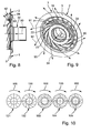
Figuren 1 und 2 dargestellte Kühlmediumverteileinrichtung; - Figur 9eine perspektivische Darstellung der in Figur 8 dargestellten Kühlmediumverteileinrichtung und
- Figur 10 fünf verschiedene Varianten eines Kühlmediumverteilkörpers mit unterschiedlichen Steggeometrien.
- Figure 1 is a perspective view of a Kühlmediumverteileinrichtung invention;
- Figure 2 is a perspective sectional view of the Kühlmediumverteileinrichtung of Figure 1;
- Figure 3 is a three-part Kühlmediumverteileinrichtung, as shown in perspective in Figure 1, in an exploded view;
- FIG. 4 shows a section of a cooling medium distributing body from FIG. 3 in a perspective view;
- Figure 5 is a two-part Kühlmediumverteileinrichtung, as shown in perspective in Figure 1, in an exploded view;
- 6 shows a section of a Kühlmediumverteilkörpers of Figure 5 in a perspective view;
- Figure 7 shows a torque transmitting device with a Kühlmediumverteileinrichtung, as shown in Figures 1 to 6 in various views and embodiments, in half section;
- FIG. 8 shows the view of a longitudinal section through the cooling medium distribution device illustrated in FIGS. 1 and 2;
- FIG. 9 is a perspective view of the cooling medium distribution device shown in FIG. 8 and FIG
- Figure 10 shows five different variants of a Kühlmediumverteilkörpers with different web geometries.
In den Figuren 1 und 2 ist eine Kühlmediumverteileinrichtung 1 in verschiedenen Ansichten perspektivisch dargestellt. Die Kühlmediumverteileinrichtung 1 dient dazu, Kühlmedium zu verteilen. Bei dem Kühlmedium handelt es sich vorzugsweise um Öl, das in einer nasslaufenden Kupplungseinrichtung zur Kühlung von Reiblamellen verwendet wird. Die erfindungsgemäße Kühlmediumverteileinrichtung 1 wird daher auch als Ölverteiler bezeichnet. Die Kühlmediumverteileinrichtung 1 umfasst einen Aufnahmeteller 2, der im Wesentlichen die Gestalt einer Kreisringscheibe 3 aufweist. Radial außen gehen von der Kreisringscheibe 3 Zähne 5, 6 und 7 aus, die Kopplungselemente darstellen. Radial innen ist von der Kreisringscheibe 3 ein Kragen 9 abgewinkelt. In dem Kragen 9 sind eine Vielzahl von Durchtrittsöffnungen 11, 12 ausgespart, die den Durchtritt von Kühlmedium in radialer Richtung ermöglichen. Der Kragen 9 geht in einen Befestigungsflansch 14 über, der mehrere Durchgangslöcher 16, 17 aufweist. die Durchgangslöcher 16, 17 dienen zum Durchführen von Befestigungselementen 19, mit deren Hilfe ein Kühlmediumverteilkörper 20 an dem Aufnahmeteller 2 befestigt ist.In Figures 1 and 2, a
Der Kühlmediumverteilkörper 20 weist eine Vielzahl von Kühlmediumverteilflächen 21 bis 23 auf, die gleichmäßig über den Umfang verteilt sind. Die Kühlmediumverteilflächen 21 bis 23 werden jeweils von zwei Stegen 25, 26; 26, 27; 27,28 begrenzt. Darüber hinaus sind die Kühlmediumverteilflächen 21 bis 23 Oberflächen von Rampen, die radial außen von einer planen Kreisringscheibenfläche 30 ausgehen und unterschiedliche Steigungen aufweisen. Radial innen ist an der Kreisringscheibenfläche 30 eine Antriebshülse 32 angebracht. Die Antriebshülse 32 hat im Wesentlichen die Gestalt eines Kreiszylindermantels, an dem diametral gegenüberliegend zwei Kopplungselemente 34, 35 ausgebildet sind. Der Aufnahmeteller 2, der Kühlmediumverteilkörper 20 und die Antriebshülse 32 können einstückig miteinander verbunden sein. Stattdessen können die Teile aber auch separat ausgebildet sein und mit Hilfe von weiteren Befestigungsmitteln, wie Schrauben oder Nieten aneinander befestigt sein. Es ist auch möglich, die Einzelteile stoffschlüssig miteinander zu verbinden, zum Beispiel durch Schweißen.The
In den Figuren 3 und 4 ist eine erfindungsgemäße Kühlmediumverteileinrichtung dargestellt, die dreiteilig aus einem Aufnahmeteller 2, einem Kühlmediumverteilkörper 20 und einer Antriebshülse 32 kombiniert ist. Der Kühlmediumverteilkörper 20 ist aus Kunststoff gegossen und durch Schnappverbindungselemente oder einen Bajonettverschluss an dem Aufnahmeteller 2 befestigbar. Alternativ kann der Kühlmediumverteilkörper 20 auch mit Hilfe von Schrauben 36, die durch Durchgangslöcher 38 in dem Kühlmediumverteilkörper 20 hindurch gesteckt werden, an dem Aufnahmeteller 2 befestigt sein. Bei der Antriebshülse 32 und dem Aufnahmeteller 2 handelt es sich um zwei separate Blechteile.FIGS. 3 and 4 show a cooling medium distribution device according to the invention, which is combined in three parts from a receiving
In den Figuren 5 und 6 ist gezeigt, dass der Aufnahmeteller 2 und der Kühlmediumverteilkörper 20 auch einteilig in einem Blechteil 40 zusammengefasst sein können. Das Blechteil 40 kann zum Beispiel durch Stanzen und Umformen aus Blech hergestellt werden. Die ebenfalls als Blechformteil ausgebildete Antriebshülse 32 kann mit Hilfe von (nicht dargestellten) Nietbolzen an dem Kühlmediumverteilkörper 20 befestigt werden. Zu diesem Zweck weist die Antriebshülse 32 einen Befestigungsflansch 41 mit Durchgangslöchern 42 auf. Die Durchgangslöcher 42 des Befestigungsflansches 41 sind beim Zusammenbau mit weiteren Durchgangslöchern 43 zur Deckung zu bringen, die in der Kreisringscheibenfläche 30 ausgespart sind. In Figur 6 ist des Weiteren angedeutet, dass die Stege 44 durch Umformen aus dem ursprünglichen Blechteil herausgestellt sind.FIGS. 5 and 6 show that the receiving
In Figur 7 ist ein Teil eines Antriebsstrangs 51 eines Kraftfahrzeugs dargestellt. Zwischen einer Antriebseinheit 53, insbesondere einer Brennkraftmaschine, von der eine Kurbelwelle 54 ausgeht, und einem Getriebe 55 ist eine nasslaufende Doppelkupplung 56 in Lamellenbauweise angeordnet. Zwischen die Antriebseinheit 53 und die Doppelkupplung 56 ist eine Drehschwingungsdämpfungseinrichtung 58 geschaltet. Bei der Drehschwingungsdämpfungseinrichtung 58 handelt es sich um ein Zweimassenschwungrad.FIG. 7 shows a part of a
Die Kurbelwelle 54 der Brennkraftmaschine 53 ist über Schraubverbindungen fest mit einem Eingangsteil der Drehschwingungsdämpfungseinrichtung 58 verbunden. Das Eingangsteil der Drehschwingungsdämpfungseinrichtung 58 ist unter Zwischenschaltung von Schraubenfedern mit einem Ausgangsteil der Drehschwingungsdämpfungseinrichtung 58 gekoppelt. Das Ausgangsteil der Drehschwingungsdämpfungseinrichtung 58 wiederum ist über ein Verbindungsteil mit einem integrierten Nabenteil drehfest mit einem Eingangsteil 64 der Doppelkupplung 56 verbunden. Das Kupplungseingangsteil 64 ist einstückig mit einem Außenlamellenträger 66 einer ersten Lamellen-Kupplungsanordnung 67 verbunden. Radial innerhalb des Außenlamellenträgers 66 ist ein Innenlamellenträger 69 der ersten Lamellen-Kupplungsanordnung 67 angeordnet. Der Innenlamellenträger 69 ist radial innen an einem Nabenteil 71 befestigt, das über eine Verzahnung drehfest mit einer ersten Getriebeeingangswelle 73 verbunden ist.The
Der Außenlamellenträger 66 der ersten Lamellen-Kupplungsanordnung 67 ist über ein Kopplungsteil 68 drehfest mit einem Außenlamellenträger 70 einer zweiten Lamellen-Kupplungsanordnung 72 verbunden. Radial innerhalb des Außenlamellenträgers 70 ist ein Innenlamellenträger 74 der zweiten Lamellen-Kupplungsanordnung 72 angeordnet, der radial innen fest mit einem Nabenteil 75 verbunden ist. Das Nabenteil 75 ist über eine Verzahnung drehfest mit einer zweiten Getriebeeingangswelle 76 verbunden, die als Hohlwelle ausgebildet ist. In der zweiten Getriebeeingangswelle 76 ist die erste Getriebeeingangswelle 73 drehbar angeordnet. Die beiden Lamellen-Kupplungsanordnungen 67 und 72 werden über Betätigungshebel 77 und 78 betätigt, deren radial innere Enden sich an Betätigungslagern abstützen. Die Betätigungslager werden mit Hilfe von Betätigungskolben in axialer Richtung betätigt.The
Die Betätigungskraft des Betätigungshebels 78 wird über einen Drucktopf 81 auf eine Lamelle 82 der Lamellen-Kupplungsanordnung 72 übertragen. In axialer Richtung zwischen dem Drucktopf 81 und der Lamelle 82 ist ein Aufnahmeteller 2 einer Kühlmediumverteileinrichtung 1, wie sie in den Figuren 1 bis 6 in verschiedenen Ausführungsformen dargestellt ist, in den Außenlamellenträger 70 eingehängt. Der Außenlamellenträger 70, der drehfest mit dem Außenlamellenträger 66 verbunden ist, ist antriebsmäßig mit der Kurbelwelle 54 verbunden. Daher dreht sich der Aufnahmeteller 2 im Betrieb der Brennkraftmaschine 53 mit Motordrehzahl. Der Kühlmediumverteilkörper 20 der Kühlmediumverteileinrichtung 1 ist radial innerhalb von Durchtrittsöffnungen 86 angeordnet, die den Durchtritt von Kühlmedium in radialer Richtung durch den Innenlamellenträger 74 hindurch ermöglichen. Die Antriebshülse 32 der Kühlmediumverteileinrichtung 1 ist mit einem Pumpenantriebsrohr 84 verbunden, das wiederum drehfest und mit einem Antriebsritzel einer (nicht dargestellten) Kühlmediumpumpe verbunden ist.The actuating force of the actuating
In der nasslaufenden Doppelkupplung 56 wird ein spezielles Kühlmedium, insbesondere ein spezielles Kühlöl, verwendet, um die im Betrieb an den Lamellen-Kupplungsanordnungen 67 und 72 entstehende Reibungswärme abzuführen. Zur Kühlung der Reibbeläge strömt das Kühlöl jeweils zwischen einer Stahllamelle und einer Reiblamelle hindurch, wobei ein Temperaturaustausch stattfindet. Durch Nuten in den Reibbelägen wird das Kühlöl radial nach außen geleitet. Auf diese Art und Weise wird das Kühlöl durch beide Lamellen-Kupplungsanordnungen 72 und 67 radial nach außen geführt. Anschließend vermischt sich das Kühlöl mit Öl in einem Getriebesumpf. Von hier wird es dann zum Kühler und dann wieder in die Kupplung gepumpt. Um die Belagsnuten gleichmäßig mit Kühlöl zu versorgen, wird das Kühlöl über die spezielle Geometrie der Kühlmediumverteilflächen an unterschiedliche axiale Positionen gefördert. Durch die im Betrieb auftretende Fliehkraft wird das Kühlöl radial nach außen an die Kupplungsbeläge geschleudert, wo es in die Belagnuten eintreten kann.In the wet-running
In den Figuren 8 und 9 ist durch einen Pfeil 90 angedeutet, dass das von der Kühlölpumpe geförderte Kühlöl durch die Antriebshülse 32 aus dem Inneren der Antriebshülse 32 zu der planen Kreisringscheibenfläche 30 gelangt. Durch die von der Motordrehzahl bewirkte Fliehkraft verteilt sich der von der Kühlölpumpe geförderte Volumenstrom gleichmäßig auf die Kühlmediumverteilflächen 21 bis 23, die an den Rampen ausgebildet sind. Dabei wird das Kühlöl durch die Stege 25 bis 28 zusätzlich beschleunigt und spritzt auf der durch die unterschiedlichen Rampensteigungswinkel vorgegebenen Richtung am Rampenende radial außen ab. Über die Anzahl der Rampen kann die Kühlölmenge für einen Belag abgestimmt werden. Besonders stark belastete Reibbeläge können so bevorzugt gekühlt werden. Durch Pfeile 91 bis 94 ist das am Rampenende abspritzende Kühlöl angedeutet. In den Figuren 8 und 9 sieht man, dass das Kühlöl von den unterschiedlichen Rampen sowohl in axialer Richtung als auch in tangentialer Richtung in unterschiedlichen Richtungen abspritzt.In the figures 8 and 9 is indicated by an
In Figur 10 ist angedeutet, dass der Kühlmediumverteilkörper unterschiedliche Rampengeometrien 101 bis 105 aufweisen kann. Die Drehrichtung im Uhrzeigersinn ist jeweils durch einen Pfeil 100 angedeutet. Je größer die Anzahl der Rampen ist, desto gleichmäßiger können die einzelnen Belagsebenen versorgt werden. Allerdings besteht bei zu vielen Rampen die Gefahr, dass das Öl in unerwünschter Weise verwirbelt wird. Durch eine scharfe Kante am Rampenende wird ein unverfälschtes Abspritzen des Kühlöls in die vorgegebene Richtung ermöglicht. Der zugehörige Radius ist kleiner als 0,5 mm. Bei 101 ist angedeutet, dass die Stege sich in radialer Richtung gerade erstrecken können. Bei 102 ist angedeutet, dass sich die Stege auch in tangentialer Richtung erstrecken können. Bei 103 ist angedeutet, dass die Stege jeweils die Gestalt von Kreisbögen aufweisen, die spiralförmig angeordnet sind. Bei 104 und 105 ist angedeutet, dass die Stege auch aus geraden Teilstücken mit Kreisbögen kombiniert sein können.In FIG. 10 it is indicated that the cooling medium distributing body can have
- 1.1.
- KühlmediumverteileinrichtungKühlmediumverteileinrichtung
- 2.Second
- AufnahmetellerShot plate
- 3.Third
- KreisringscheibeAnnular disk
- 5.5th
- Kopplungselementcoupling element
- 6.6th
- Kopplungselementcoupling element
- 7.7th
- Kopplungselementcoupling element
- 9.9th
- Kragencollar
- 11.11th
- DurchtrittsöffnungThrough opening
- 12.12th
- DurchtrittsöffnungThrough opening
- 14.14th
- Befestigungsflanschmounting flange
- 16.16th
- DurchgangslochThrough Hole
- 17.17th
- DurchgangslochThrough Hole
- 19.19th
- Befestigungselementfastener
- 20.20th
- KühlmediumverteilkörperKühlmediumverteilkörper
- 21.21st
- KühlmediumverteilflächenKühlmediumverteilflächen
- 22.22nd
- KühlmediumverteilflächenKühlmediumverteilflächen
- 23.23rd
- KühlmediumverteilflächenKühlmediumverteilflächen
- 25.25th
- Stegweb
- 26.26th
- Stegweb
- 27.27th
- Stegweb
- 28.28th
- Stegweb
- 30.30th
- KreisringscheibenflächeAnnular disk surface
- 32.32nd
- Antriebshülsedrive sleeve
- 34.34th
- Kopplungselementcoupling element
- 35.35th
- Kopplungselementcoupling element
- 36.36th
- Schraubenscrew
- 38.38th
- DurchgangslochThrough Hole
- 40.40th
- Blechteilsheet metal part
- 41.41st
- Befestigungsflanschmounting flange
- 42.42nd
- DurchgangslochThrough Hole
- 43.43rd
- DurchgangslochThrough Hole
- 44.44th
- Stegweb
- 51.51st
- Antriebsstrangpowertrain
- 53.53rd
- Antriebseinheitdrive unit
- 54.54th
- Kurbelwellecrankshaft
- 55.55th
- Getriebetransmission
- 56.56th
- DoppelkupplungDouble coupling
- 58.58th
- DrehschwingungsdämpfungseinrichtungTorsional vibration damping device
- 64.64th
- KupplungseingangsteilClutch input part
- 66.66th
- AußenlamellenträgerExternal disk carrier
- 67.67th
- erste Lamellen-Kupplungsanordnungfirst disk clutch assembly
- 68.68th
- Kopplungsteilcoupling part
- 69.69th
- InnenlamellenträgerInner disk carrier
- 70.70th
- AußenlamellenträgerExternal disk carrier
- 71.71st
- Nabelteilnavel part
- 72.72nd
- zweite Lamellen-Kupplungsanordnungsecond disk clutch assembly
- 73.73rd
- GetriebeeingangswelleTransmission input shaft
- 74.74th
- InnenlamellenträgerInner disk carrier
- 75.75th
- Nabelteilnavel part
- 76.76th
- GetriebeeingangswelleTransmission input shaft
- 77.77th
- Betätigungshebelactuating lever
- 78.78th
- Betätigungshebelactuating lever
- 81.81st
- Drucktopfpressure cooker
- 82.82nd
- Lamellelamella
- 84.84th
- PumpenantriebsrohrPump drive tube
- 86.86th
- DurchtrittsöffnungThrough opening
- 90.90th
- Pfeilarrow
- 91.91st
- Pfeilarrow
- 92.92nd
- Pfeilarrow
- 93.93rd
- Pfeilarrow
- 94.94th
- Pfeilarrow
- 100.100th
- Pfeilarrow
- 101.One hundred and first
- KühlmediumverteilkörperKühlmediumverteilkörper
- 102.102nd
- KühlmediumverteilkörperKühlmediumverteilkörper
- 103.103rd
- KühlmediumverteilkörperKühlmediumverteilkörper
- 104.104th
- KühlmediumverteilkörperKühlmediumverteilkörper
- 105.105th
- KühlmediumverteilkörperKühlmediumverteilkörper
Claims (10)
Applications Claiming Priority (1)
| Application Number | Priority Date | Filing Date | Title |
|---|---|---|---|
| DE102006003923 | 2006-01-26 |
Publications (3)
| Publication Number | Publication Date |
|---|---|
| EP1813831A1 true EP1813831A1 (en) | 2007-08-01 |
| EP1813831B1 EP1813831B1 (en) | 2010-02-17 |
| EP1813831B2 EP1813831B2 (en) | 2017-06-07 |
Family
ID=37946455
Family Applications (1)
| Application Number | Title | Priority Date | Filing Date |
|---|---|---|---|
| EP06026391.0A Not-in-force EP1813831B2 (en) | 2006-01-26 | 2006-12-20 | Cooling medium distribution device |
Country Status (5)
| Country | Link |
|---|---|
| US (1) | US7673730B2 (en) |
| EP (1) | EP1813831B2 (en) |
| CN (1) | CN101008424B (en) |
| AT (1) | ATE458152T1 (en) |
| DE (1) | DE502006006167D1 (en) |
Cited By (4)
| Publication number | Priority date | Publication date | Assignee | Title |
|---|---|---|---|---|
| EP1914434A3 (en) * | 2006-10-21 | 2010-03-24 | LuK Lamellen und Kupplungsbau Beteiligungs KG | Torque transmission device |
| DE102012201510A1 (en) | 2012-02-02 | 2013-08-08 | Zf Friedrichshafen Ag | clutch assembly |
| DE102012201507A1 (en) * | 2012-02-02 | 2013-08-08 | Zf Friedrichshafen Ag | clutch assembly |
| DE102015220446B3 (en) * | 2015-10-20 | 2016-12-15 | Magna powertrain gmbh & co kg | Wet running coupling unit |
Families Citing this family (13)
| Publication number | Priority date | Publication date | Assignee | Title |
|---|---|---|---|---|
| DE112008001561B4 (en) * | 2007-07-02 | 2017-09-21 | Schaeffler Technologies AG & Co. KG | Coupling arrangement, in particular wet-running dual clutch arrangement |
| US20100140036A1 (en) * | 2008-12-08 | 2010-06-10 | Gm Global Technology Operations, Inc. | Compact dry dual clutch module |
| US8919512B2 (en) * | 2011-03-30 | 2014-12-30 | Borgwarner Inc. | Wet clutch module with integrated heat exchanger |
| DE102011083805A1 (en) * | 2011-09-30 | 2013-04-04 | Schaeffler Technologies AG & Co. KG | Adjustable coolant pump with integrated pressure chamber |
| DE102011084853A1 (en) * | 2011-10-20 | 2013-04-25 | Schaeffler Technologies AG & Co. KG | Adjustable coolant pump |
| DE112013002627B4 (en) * | 2012-05-22 | 2020-02-20 | Schaeffler Technologies AG & Co. KG | wet clutch |
| JP5967291B2 (en) * | 2013-03-11 | 2016-08-10 | 日産自動車株式会社 | Driving force transmission device |
| US9163715B2 (en) | 2013-08-23 | 2015-10-20 | American Axle & Manufacturing, Inc. | Clutched power transmitting device with filter element |
| US9353846B2 (en) | 2013-08-23 | 2016-05-31 | American Axle & Manufacturing, Inc. | Power transmitting component with torque transfer device configured with fluid evacuation and lubrication system |
| US9303696B2 (en) | 2013-08-23 | 2016-04-05 | American Axle & Manufacturing, Inc. | Optimized outer clutch housing for reduced spin loss, improved oil flow and improved clutch durability |
| DE102014212808A1 (en) * | 2014-07-02 | 2016-01-07 | Schaeffler Technologies AG & Co. KG | Optimization of the oil distribution of a wet / moist multi-plate clutch |
| CN104265641A (en) * | 2014-09-09 | 2015-01-07 | 浙江海洋学院 | Flow controllable type cutter suction pump |
| CN112943684B (en) * | 2021-02-07 | 2022-12-27 | 武汉船用机械有限责任公司 | Deep well immersed pump impeller auxiliary device and pump head |
Citations (4)
| Publication number | Priority date | Publication date | Assignee | Title |
|---|---|---|---|---|
| US4473144A (en) * | 1982-05-18 | 1984-09-25 | International Harvester Co. | Transmission clutch hub |
| US4971184A (en) * | 1989-08-07 | 1990-11-20 | General Motors Corporation | Overrunning clutch with lubricant spreading and distribution means |
| US20030085094A1 (en) * | 2001-11-05 | 2003-05-08 | Nsk-Warner K.K. | Starting clutch |
| WO2004104439A1 (en) * | 2003-05-24 | 2004-12-02 | Dr. Ing. H.C. F. Porsche Aktiengesellschaft | Clutch device, in particular a multiplate clutch for a double-clutch gearbox |
Family Cites Families (4)
| Publication number | Priority date | Publication date | Assignee | Title |
|---|---|---|---|---|
| US3540557A (en) * | 1969-04-01 | 1970-11-17 | Caterpillar Tractor Co | Fluid pressure booster for sequentially releasing clutch and engaging brake |
| DE3047778A1 (en) † | 1980-12-18 | 1982-07-08 | Fichtel & Sachs Ag, 8720 Schweinfurt | HYDRAULIC CLUTCH BRAKE FOR WET COUPLINGS |
| US4446953A (en) * | 1981-11-17 | 1984-05-08 | International Harvester Co. | Clutch oil shield and diverter |
| DE3661035D1 (en) * | 1985-06-29 | 1988-12-01 | Klifa Gmbh & Co | Water pump impeller |
-
2006
- 2006-12-20 EP EP06026391.0A patent/EP1813831B2/en not_active Not-in-force
- 2006-12-20 DE DE502006006167T patent/DE502006006167D1/en active Active
- 2006-12-20 AT AT06026391T patent/ATE458152T1/en active
-
2007
- 2007-01-16 CN CN2007100017549A patent/CN101008424B/en not_active Expired - Fee Related
- 2007-01-18 US US11/654,973 patent/US7673730B2/en not_active Expired - Fee Related
Patent Citations (4)
| Publication number | Priority date | Publication date | Assignee | Title |
|---|---|---|---|---|
| US4473144A (en) * | 1982-05-18 | 1984-09-25 | International Harvester Co. | Transmission clutch hub |
| US4971184A (en) * | 1989-08-07 | 1990-11-20 | General Motors Corporation | Overrunning clutch with lubricant spreading and distribution means |
| US20030085094A1 (en) * | 2001-11-05 | 2003-05-08 | Nsk-Warner K.K. | Starting clutch |
| WO2004104439A1 (en) * | 2003-05-24 | 2004-12-02 | Dr. Ing. H.C. F. Porsche Aktiengesellschaft | Clutch device, in particular a multiplate clutch for a double-clutch gearbox |
Cited By (9)
| Publication number | Priority date | Publication date | Assignee | Title |
|---|---|---|---|---|
| EP1914434A3 (en) * | 2006-10-21 | 2010-03-24 | LuK Lamellen und Kupplungsbau Beteiligungs KG | Torque transmission device |
| US7966901B2 (en) | 2006-10-21 | 2011-06-28 | Schaeffler Technologies Gmbh & Co. Kg | Torque transfer device |
| DE102012201510A1 (en) | 2012-02-02 | 2013-08-08 | Zf Friedrichshafen Ag | clutch assembly |
| DE102012201507A1 (en) * | 2012-02-02 | 2013-08-08 | Zf Friedrichshafen Ag | clutch assembly |
| WO2013113529A1 (en) | 2012-02-02 | 2013-08-08 | Zf Friedrichshafen Ag | Clutch arrangement |
| DE102015220446B3 (en) * | 2015-10-20 | 2016-12-15 | Magna powertrain gmbh & co kg | Wet running coupling unit |
| CN106907404A (en) * | 2015-10-20 | 2017-06-30 | 麦格纳动力系有限两合公司 | The clutch unit of wet operation |
| CN106907404B (en) * | 2015-10-20 | 2019-04-12 | 麦格纳动力系有限两合公司 | The clutch unit of wet operation |
| US10563702B2 (en) | 2015-10-20 | 2020-02-18 | Magna powertrain gmbh & co kg | Wet-running clutch unit |
Also Published As
| Publication number | Publication date |
|---|---|
| US7673730B2 (en) | 2010-03-09 |
| DE502006006167D1 (en) | 2010-04-01 |
| EP1813831B1 (en) | 2010-02-17 |
| CN101008424A (en) | 2007-08-01 |
| EP1813831B2 (en) | 2017-06-07 |
| ATE458152T1 (en) | 2010-03-15 |
| US20070170034A1 (en) | 2007-07-26 |
| CN101008424B (en) | 2011-05-11 |
Similar Documents
| Publication | Publication Date | Title |
|---|---|---|
| EP1813831B2 (en) | Cooling medium distribution device | |
| DE102013203510B4 (en) | Coupling arrangement for a transmission with improved cooling | |
| EP1364134B1 (en) | Clutch arrangement | |
| EP2387673B2 (en) | Clutch unit | |
| DE112011101231B4 (en) | Double coupling | |
| EP1783388B1 (en) | Multi-disc clutch device | |
| WO2012146228A1 (en) | Torsional vibration damper | |
| WO2015144157A1 (en) | Clutch system with dual clutch and csc with an axial csc bearing comprising a platform for receiving the csc, and powertrain | |
| DE112011105537B4 (en) | Dry double clutch | |
| DE102006028552A1 (en) | Clutch device has clutch plate and pendulum mass mounting device of centrifugal force pendulum device enfolds several pendulum masses which are movably attached at pendulum mass mounting device | |
| WO2015007283A1 (en) | Bearing assembly for an intermediate shaft in a clutch of a hybrid module | |
| DE60012379T2 (en) | Torque converter with a lock-up clutch with a spring-loaded piston | |
| DE102014205506A1 (en) | Bearing and axial support of a double clutch on a transmission input shaft | |
| DE102008042466A1 (en) | Wet-running starting clutch | |
| DE102020112616B3 (en) | Multi-plate clutch arrangement with spring plate units acting independently of one another for connecting two part-plates to an output shaft | |
| DE112006000595T5 (en) | coupling device | |
| EP3571425A1 (en) | Torque transmission assembly | |
| EP3953596B1 (en) | Multiple disc clutch, in particular for a hybrid drive train | |
| EP1729025B1 (en) | Mulitple clutch device | |
| WO2016000707A1 (en) | Optimizing the oil distribution of a wet/moist multi-disc clutch | |
| DE102021106623B3 (en) | Coupling device with an axial toothing | |
| DE102006060228A1 (en) | Coolant distribution device e.g. oil distributor, has coolant distribution surfaces implemented so that coolant conveyed outwardly in radial direction has different axial coolant spray-off points and/or coolant spray-off devices | |
| DE102006042441B4 (en) | Hydrodynamic torque converter with a lock-up clutch | |
| EP3927991B1 (en) | Compact clutch assembly with a support body | |
| DE102017130853B4 (en) | coupling device |
Legal Events
| Date | Code | Title | Description |
|---|---|---|---|
| PUAI | Public reference made under article 153(3) epc to a published international application that has entered the european phase |
Free format text: ORIGINAL CODE: 0009012 |
|
| AK | Designated contracting states |
Kind code of ref document: A1 Designated state(s): AT BE BG CH CY CZ DE DK EE ES FI FR GB GR HU IE IS IT LI LT LU LV MC NL PL PT RO SE SI SK TR |
|
| AX | Request for extension of the european patent |
Extension state: AL BA HR MK YU |
|
| 17P | Request for examination filed |
Effective date: 20080201 |
|
| 17Q | First examination report despatched |
Effective date: 20080228 |
|
| AKX | Designation fees paid |
Designated state(s): AT BE BG CH CY CZ DE DK EE ES FI FR GB GR HU IE IS IT LI LT LU LV MC NL PL PT RO SE SI SK TR |
|
| GRAP | Despatch of communication of intention to grant a patent |
Free format text: ORIGINAL CODE: EPIDOSNIGR1 |
|
| GRAS | Grant fee paid |
Free format text: ORIGINAL CODE: EPIDOSNIGR3 |
|
| GRAA | (expected) grant |
Free format text: ORIGINAL CODE: 0009210 |
|
| AK | Designated contracting states |
Kind code of ref document: B1 Designated state(s): AT BE BG CH CY CZ DE DK EE ES FI FR GB GR HU IE IS IT LI LT LU LV MC NL PL PT RO SE SI SK TR |
|
| REG | Reference to a national code |
Ref country code: GB Ref legal event code: FG4D Free format text: NOT ENGLISH |
|
| REG | Reference to a national code |
Ref country code: CH Ref legal event code: EP |
|
| REG | Reference to a national code |
Ref country code: IE Ref legal event code: FG4D Free format text: LANGUAGE OF EP DOCUMENT: GERMAN |
|
| REF | Corresponds to: |
Ref document number: 502006006167 Country of ref document: DE Date of ref document: 20100401 Kind code of ref document: P |
|
| REG | Reference to a national code |
Ref country code: NL Ref legal event code: VDEP Effective date: 20100217 |
|
| LTIE | Lt: invalidation of european patent or patent extension |
Effective date: 20100217 |
|
| PG25 | Lapsed in a contracting state [announced via postgrant information from national office to epo] |
Ref country code: PT Free format text: LAPSE BECAUSE OF FAILURE TO SUBMIT A TRANSLATION OF THE DESCRIPTION OR TO PAY THE FEE WITHIN THE PRESCRIBED TIME-LIMIT Effective date: 20100617 Ref country code: LT Free format text: LAPSE BECAUSE OF FAILURE TO SUBMIT A TRANSLATION OF THE DESCRIPTION OR TO PAY THE FEE WITHIN THE PRESCRIBED TIME-LIMIT Effective date: 20100217 Ref country code: IS Free format text: LAPSE BECAUSE OF FAILURE TO SUBMIT A TRANSLATION OF THE DESCRIPTION OR TO PAY THE FEE WITHIN THE PRESCRIBED TIME-LIMIT Effective date: 20100617 Ref country code: ES Free format text: LAPSE BECAUSE OF FAILURE TO SUBMIT A TRANSLATION OF THE DESCRIPTION OR TO PAY THE FEE WITHIN THE PRESCRIBED TIME-LIMIT Effective date: 20100528 |
|
| PG25 | Lapsed in a contracting state [announced via postgrant information from national office to epo] |
Ref country code: FI Free format text: LAPSE BECAUSE OF FAILURE TO SUBMIT A TRANSLATION OF THE DESCRIPTION OR TO PAY THE FEE WITHIN THE PRESCRIBED TIME-LIMIT Effective date: 20100217 Ref country code: PL Free format text: LAPSE BECAUSE OF FAILURE TO SUBMIT A TRANSLATION OF THE DESCRIPTION OR TO PAY THE FEE WITHIN THE PRESCRIBED TIME-LIMIT Effective date: 20100217 Ref country code: SI Free format text: LAPSE BECAUSE OF FAILURE TO SUBMIT A TRANSLATION OF THE DESCRIPTION OR TO PAY THE FEE WITHIN THE PRESCRIBED TIME-LIMIT Effective date: 20100217 Ref country code: LV Free format text: LAPSE BECAUSE OF FAILURE TO SUBMIT A TRANSLATION OF THE DESCRIPTION OR TO PAY THE FEE WITHIN THE PRESCRIBED TIME-LIMIT Effective date: 20100217 |
|
| REG | Reference to a national code |
Ref country code: IE Ref legal event code: FD4D |
|
| RAP2 | Party data changed (patent owner data changed or rights of a patent transferred) |
Owner name: SCHAEFFLER TECHNOLOGIES GMBH & CO. KG |
|
| PG25 | Lapsed in a contracting state [announced via postgrant information from national office to epo] |
Ref country code: IE Free format text: LAPSE BECAUSE OF FAILURE TO SUBMIT A TRANSLATION OF THE DESCRIPTION OR TO PAY THE FEE WITHIN THE PRESCRIBED TIME-LIMIT Effective date: 20100217 Ref country code: CY Free format text: LAPSE BECAUSE OF FAILURE TO SUBMIT A TRANSLATION OF THE DESCRIPTION OR TO PAY THE FEE WITHIN THE PRESCRIBED TIME-LIMIT Effective date: 20100217 Ref country code: SE Free format text: LAPSE BECAUSE OF FAILURE TO SUBMIT A TRANSLATION OF THE DESCRIPTION OR TO PAY THE FEE WITHIN THE PRESCRIBED TIME-LIMIT Effective date: 20100217 Ref country code: GR Free format text: LAPSE BECAUSE OF FAILURE TO SUBMIT A TRANSLATION OF THE DESCRIPTION OR TO PAY THE FEE WITHIN THE PRESCRIBED TIME-LIMIT Effective date: 20100518 Ref country code: NL Free format text: LAPSE BECAUSE OF FAILURE TO SUBMIT A TRANSLATION OF THE DESCRIPTION OR TO PAY THE FEE WITHIN THE PRESCRIBED TIME-LIMIT Effective date: 20100217 Ref country code: RO Free format text: LAPSE BECAUSE OF FAILURE TO SUBMIT A TRANSLATION OF THE DESCRIPTION OR TO PAY THE FEE WITHIN THE PRESCRIBED TIME-LIMIT Effective date: 20100217 Ref country code: EE Free format text: LAPSE BECAUSE OF FAILURE TO SUBMIT A TRANSLATION OF THE DESCRIPTION OR TO PAY THE FEE WITHIN THE PRESCRIBED TIME-LIMIT Effective date: 20100217 |
|
| PLBI | Opposition filed |
Free format text: ORIGINAL CODE: 0009260 |
|
| PG25 | Lapsed in a contracting state [announced via postgrant information from national office to epo] |
Ref country code: SK Free format text: LAPSE BECAUSE OF FAILURE TO SUBMIT A TRANSLATION OF THE DESCRIPTION OR TO PAY THE FEE WITHIN THE PRESCRIBED TIME-LIMIT Effective date: 20100217 Ref country code: CZ Free format text: LAPSE BECAUSE OF FAILURE TO SUBMIT A TRANSLATION OF THE DESCRIPTION OR TO PAY THE FEE WITHIN THE PRESCRIBED TIME-LIMIT Effective date: 20100217 Ref country code: BG Free format text: LAPSE BECAUSE OF FAILURE TO SUBMIT A TRANSLATION OF THE DESCRIPTION OR TO PAY THE FEE WITHIN THE PRESCRIBED TIME-LIMIT Effective date: 20100517 |
|
| PLAX | Notice of opposition and request to file observation + time limit sent |
Free format text: ORIGINAL CODE: EPIDOSNOBS2 |
|
| 26 | Opposition filed |
Opponent name: ZF FRIEDRICHSHAFEN AG Effective date: 20101116 |
|
| PG25 | Lapsed in a contracting state [announced via postgrant information from national office to epo] |
Ref country code: DK Free format text: LAPSE BECAUSE OF FAILURE TO SUBMIT A TRANSLATION OF THE DESCRIPTION OR TO PAY THE FEE WITHIN THE PRESCRIBED TIME-LIMIT Effective date: 20100217 |
|
| PG25 | Lapsed in a contracting state [announced via postgrant information from national office to epo] |
Ref country code: IT Free format text: LAPSE BECAUSE OF FAILURE TO SUBMIT A TRANSLATION OF THE DESCRIPTION OR TO PAY THE FEE WITHIN THE PRESCRIBED TIME-LIMIT Effective date: 20100217 |
|
| PLAF | Information modified related to communication of a notice of opposition and request to file observations + time limit |
Free format text: ORIGINAL CODE: EPIDOSCOBS2 |
|
| BERE | Be: lapsed |
Owner name: LUK LAMELLEN UND KUPPLUNGSBAU BETEILIGUNGS K.G. Effective date: 20101231 |
|
| PLBB | Reply of patent proprietor to notice(s) of opposition received |
Free format text: ORIGINAL CODE: EPIDOSNOBS3 |
|
| PG25 | Lapsed in a contracting state [announced via postgrant information from national office to epo] |
Ref country code: MC Free format text: LAPSE BECAUSE OF NON-PAYMENT OF DUE FEES Effective date: 20101231 |
|
| REG | Reference to a national code |
Ref country code: CH Ref legal event code: PL |
|
| GBPC | Gb: european patent ceased through non-payment of renewal fee |
Effective date: 20101220 |
|
| REG | Reference to a national code |
Ref country code: FR Ref legal event code: ST Effective date: 20110831 |
|
| PG25 | Lapsed in a contracting state [announced via postgrant information from national office to epo] |
Ref country code: BE Free format text: LAPSE BECAUSE OF NON-PAYMENT OF DUE FEES Effective date: 20101231 |
|
| PG25 | Lapsed in a contracting state [announced via postgrant information from national office to epo] |
Ref country code: LI Free format text: LAPSE BECAUSE OF NON-PAYMENT OF DUE FEES Effective date: 20101231 Ref country code: CH Free format text: LAPSE BECAUSE OF NON-PAYMENT OF DUE FEES Effective date: 20101231 Ref country code: FR Free format text: LAPSE BECAUSE OF NON-PAYMENT OF DUE FEES Effective date: 20110103 |
|
| PG25 | Lapsed in a contracting state [announced via postgrant information from national office to epo] |
Ref country code: GB Free format text: LAPSE BECAUSE OF NON-PAYMENT OF DUE FEES Effective date: 20101220 |
|
| RAP2 | Party data changed (patent owner data changed or rights of a patent transferred) |
Owner name: SCHAEFFLER TECHNOLOGIES AG & CO. KG |
|
| PG25 | Lapsed in a contracting state [announced via postgrant information from national office to epo] |
Ref country code: LU Free format text: LAPSE BECAUSE OF NON-PAYMENT OF DUE FEES Effective date: 20101220 Ref country code: HU Free format text: LAPSE BECAUSE OF FAILURE TO SUBMIT A TRANSLATION OF THE DESCRIPTION OR TO PAY THE FEE WITHIN THE PRESCRIBED TIME-LIMIT Effective date: 20100818 |
|
| REG | Reference to a national code |
Ref country code: DE Ref legal event code: R081 Ref document number: 502006006167 Country of ref document: DE Owner name: SCHAEFFLER TECHNOLOGIES AG & CO. KG, DE Free format text: FORMER OWNER: SCHAEFFLER TECHNOLOGIES GMBH & CO. KG, 91074 HERZOGENAURACH, DE Effective date: 20120828 Ref country code: DE Ref legal event code: R081 Ref document number: 502006006167 Country of ref document: DE Owner name: SCHAEFFLER TECHNOLOGIES GMBH & CO. KG, DE Free format text: FORMER OWNER: SCHAEFFLER TECHNOLOGIES GMBH & CO. KG, 91074 HERZOGENAURACH, DE Effective date: 20120828 |
|
| PG25 | Lapsed in a contracting state [announced via postgrant information from national office to epo] |
Ref country code: TR Free format text: LAPSE BECAUSE OF FAILURE TO SUBMIT A TRANSLATION OF THE DESCRIPTION OR TO PAY THE FEE WITHIN THE PRESCRIBED TIME-LIMIT Effective date: 20100217 |
|
| REG | Reference to a national code |
Ref country code: AT Ref legal event code: MM01 Ref document number: 458152 Country of ref document: AT Kind code of ref document: T Effective date: 20111220 |
|
| APAH | Appeal reference modified |
Free format text: ORIGINAL CODE: EPIDOSCREFNO |
|
| APBM | Appeal reference recorded |
Free format text: ORIGINAL CODE: EPIDOSNREFNO |
|
| APBP | Date of receipt of notice of appeal recorded |
Free format text: ORIGINAL CODE: EPIDOSNNOA2O |
|
| PG25 | Lapsed in a contracting state [announced via postgrant information from national office to epo] |
Ref country code: AT Free format text: LAPSE BECAUSE OF NON-PAYMENT OF DUE FEES Effective date: 20111220 |
|
| APBQ | Date of receipt of statement of grounds of appeal recorded |
Free format text: ORIGINAL CODE: EPIDOSNNOA3O |
|
| RAP2 | Party data changed (patent owner data changed or rights of a patent transferred) |
Owner name: SCHAEFFLER TECHNOLOGIES GMBH & CO. KG |
|
| REG | Reference to a national code |
Ref country code: DE Ref legal event code: R081 Ref document number: 502006006167 Country of ref document: DE Owner name: SCHAEFFLER TECHNOLOGIES AG & CO. KG, DE Free format text: FORMER OWNER: SCHAEFFLER TECHNOLOGIES AG & CO. KG, 91074 HERZOGENAURACH, DE Effective date: 20140214 Ref country code: DE Ref legal event code: R081 Ref document number: 502006006167 Country of ref document: DE Owner name: SCHAEFFLER TECHNOLOGIES GMBH & CO. KG, DE Free format text: FORMER OWNER: SCHAEFFLER TECHNOLOGIES AG & CO. KG, 91074 HERZOGENAURACH, DE Effective date: 20140214 |
|
| PLAB | Opposition data, opponent's data or that of the opponent's representative modified |
Free format text: ORIGINAL CODE: 0009299OPPO |
|
| R26 | Opposition filed (corrected) |
Opponent name: ZF FRIEDRICHSHAFEN AG Effective date: 20101116 |
|
| RAP2 | Party data changed (patent owner data changed or rights of a patent transferred) |
Owner name: SCHAEFFLER TECHNOLOGIES AG & CO. KG |
|
| REG | Reference to a national code |
Ref country code: DE Ref legal event code: R081 Ref document number: 502006006167 Country of ref document: DE Owner name: SCHAEFFLER TECHNOLOGIES AG & CO. KG, DE Free format text: FORMER OWNER: SCHAEFFLER TECHNOLOGIES GMBH & CO. KG, 91074 HERZOGENAURACH, DE Effective date: 20150213 |
|
| PLAB | Opposition data, opponent's data or that of the opponent's representative modified |
Free format text: ORIGINAL CODE: 0009299OPPO |
|
| R26 | Opposition filed (corrected) |
Opponent name: ZF FRIEDRICHSHAFEN AG Effective date: 20101116 |
|
| APBU | Appeal procedure closed |
Free format text: ORIGINAL CODE: EPIDOSNNOA9O |
|
| PUAH | Patent maintained in amended form |
Free format text: ORIGINAL CODE: 0009272 |
|
| STAA | Information on the status of an ep patent application or granted ep patent |
Free format text: STATUS: PATENT MAINTAINED AS AMENDED |
|
| 27A | Patent maintained in amended form |
Effective date: 20170607 |
|
| AK | Designated contracting states |
Kind code of ref document: B2 Designated state(s): AT BE BG CH CY CZ DE DK EE ES FI FR GB GR HU IE IS IT LI LT LU LV MC NL PL PT RO SE SI SK TR |
|
| REG | Reference to a national code |
Ref country code: DE Ref legal event code: R102 Ref document number: 502006006167 Country of ref document: DE |
|
| PUAH | Patent maintained in amended form |
Free format text: ORIGINAL CODE: 0009272 |
|
| STAA | Information on the status of an ep patent application or granted ep patent |
Free format text: STATUS: PATENT MAINTAINED AS AMENDED |
|
| PGFP | Annual fee paid to national office [announced via postgrant information from national office to epo] |
Ref country code: DE Payment date: 20190228 Year of fee payment: 13 |
|
| PGFP | Annual fee paid to national office [announced via postgrant information from national office to epo] |
Ref country code: DE Payment date: 20190228 Year of fee payment: 13 |
|
| REG | Reference to a national code |
Ref country code: DE Ref legal event code: R119 Ref document number: 502006006167 Country of ref document: DE |
|
| PG25 | Lapsed in a contracting state [announced via postgrant information from national office to epo] |
Ref country code: DE Free format text: LAPSE BECAUSE OF NON-PAYMENT OF DUE FEES Effective date: 20200701 |
|
| P01 | Opt-out of the competence of the unified patent court (upc) registered |
Effective date: 20230522 |