EP1813803A1 - Pompe à carburant entraîné par un matériau à mémoire de forme - Google Patents
Pompe à carburant entraîné par un matériau à mémoire de forme Download PDFInfo
- Publication number
- EP1813803A1 EP1813803A1 EP06425042A EP06425042A EP1813803A1 EP 1813803 A1 EP1813803 A1 EP 1813803A1 EP 06425042 A EP06425042 A EP 06425042A EP 06425042 A EP06425042 A EP 06425042A EP 1813803 A1 EP1813803 A1 EP 1813803A1
- Authority
- EP
- European Patent Office
- Prior art keywords
- fuel pump
- shape memory
- memory material
- flexible membrane
- pumping chamber
- Prior art date
- Legal status (The legal status is an assumption and is not a legal conclusion. Google has not performed a legal analysis and makes no representation as to the accuracy of the status listed.)
- Withdrawn
Links
Images
Classifications
-
- F—MECHANICAL ENGINEERING; LIGHTING; HEATING; WEAPONS; BLASTING
- F02—COMBUSTION ENGINES; HOT-GAS OR COMBUSTION-PRODUCT ENGINE PLANTS
- F02M—SUPPLYING COMBUSTION ENGINES IN GENERAL WITH COMBUSTIBLE MIXTURES OR CONSTITUENTS THEREOF
- F02M37/00—Apparatus or systems for feeding liquid fuel from storage containers to carburettors or fuel-injection apparatus; Arrangements for purifying liquid fuel specially adapted for, or arranged on, internal-combustion engines
- F02M37/04—Feeding by means of driven pumps
- F02M37/046—Arrangements for driving diaphragm-type pumps
-
- F—MECHANICAL ENGINEERING; LIGHTING; HEATING; WEAPONS; BLASTING
- F04—POSITIVE - DISPLACEMENT MACHINES FOR LIQUIDS; PUMPS FOR LIQUIDS OR ELASTIC FLUIDS
- F04B—POSITIVE-DISPLACEMENT MACHINES FOR LIQUIDS; PUMPS
- F04B43/00—Machines, pumps, or pumping installations having flexible working members
- F04B43/0009—Special features
- F04B43/0054—Special features particularities of the flexible members
-
- F—MECHANICAL ENGINEERING; LIGHTING; HEATING; WEAPONS; BLASTING
- F05—INDEXING SCHEMES RELATING TO ENGINES OR PUMPS IN VARIOUS SUBCLASSES OF CLASSES F01-F04
- F05C—INDEXING SCHEME RELATING TO MATERIALS, MATERIAL PROPERTIES OR MATERIAL CHARACTERISTICS FOR MACHINES, ENGINES OR PUMPS OTHER THAN NON-POSITIVE-DISPLACEMENT MACHINES OR ENGINES
- F05C2251/00—Material properties
- F05C2251/08—Shape memory
Definitions
- the present invention relates to a fuel pump for an internal combustion engine.
- At least one fuel pump is present which has the function of feeding the fuel from a tank to an injection system.
- a modern internal combustion engine with direct injection of the fuel comprises both a low pressure fuel pump positioned in correspondence with the petrol tank and a successive high pressure fuel pump positioned inside the engine compartment.
- a low pressure fuel pump normally comprises an electric motor, which operates the pump itself; this construction solution simplifies the positioning and the fitting of the fuel pump inside the fuel tank, but is also bulky and heavy due to the presence of the electric motor.
- a high pressure fuel pump comprises at least one cylinder equipped with a piston mechanically operated by the engine shaft in order to have a reciprocating motion inside said cylinder; a monodirectional inlet valve, which allows the fuel to flow into the cylinder, and a monodirectional outlet valve, which allows the fuel to flow out of the cylinder are positioned on the top of the cylinder.
- the high pressure fuel pump is sized to feed in all operating conditions a quantity of fuel in excess of the effective consumption, and downstream the fuel pump there is a pressure regulator that maintains the pressure level of the fuel equal to a desired value discharging the excess fuel towards a recirculation channel which returns the excess fuel to the tank.
- the fuel pump must be sized to feed a quantity of fuel equal to the maximum possible consumption; however, this condition of maximum possible consumption rarely occurs, and in all the remaining operating conditions the quantity of fuel fed to the fuel pump is much greater than the effective consumption and, therefore, a considerable part of this fuel must be discharged by the pressure regulator in the tank.
- variable flow high pressure fuel pumps of the type described above are particularly complex and expensive due to the presence of the electromagnetic actuator and the electronics for piloting and control thereof. Moreover, there is a continual alternation of fuel entering and leaving the cylinder through the inlet valve and this continual alternate stream of fuel entering and leaving clearly entails waste of part of the energy used by the pump.
- a fuel pump is made for an internal combustion engine according to the appended claims.
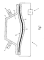
- the fuel pump 1 comprises a pumping chamber 2 with variable volume, a monodirectional inlet valve 3, communicating with the pumping chamber 2 and a monodirectional outlet valve 4 communicating with the pumping chamber 2.
- the pumping chamber 2 is contained inside a rigid open container 5 and is delimited by a flexible membrane 6, which is connected to the rigid container 5 and is made of hyperelastic or rigid polymeric material; moreover the flexible membrane 6 is equipped with an actuating device 7 that acts on the flexible membrane 6 to cyclically vary the volume of the pumping chamber 2 and therefore actuating the fuel pumping.
- the actuator device 7 comprises a shape memory material 8 that modifies its geometry upon application of an external influence of a physical nature and is mechanically coupled with the flexible membrane 6, and a piloting device 9 to cyclically apply an external influence of a physical nature to the shape memory material 8.
- the shape memory material 8 is a Shape Memory Alloy (SMA) capable of changing its physical characteristics upon application of an external influence of a physical nature; in particular metal alloys are used (for example nickel-titanium or a copper-based alloy) capable of changing its dimensions upon application of heat.
- SMA Shape Memory Alloy
- metal alloys for example nickel-titanium or a copper-based alloy
- the variation of the geometry of the shape memory material 8 is obtained by heating (i.e. by raising the temperature) of the shape memory material 8 itself.
- the shape memory material 8 is of a given length, while when the temperature of the shape memory material 8 exceeds a set temperature threshold (depending on the chemical-physical characteristics of the material), the shape memory material 8 shortens by a predetermined quantity (depending on the chemical-physical characteristics of the material) generating a reduction in the distance existing between the extremities of the shape memory material 8 itself.
- the shape memory material 8 is "two-way", i.e. it shortens when heated and lengthens spontaneously returning to its initial size when cooled.
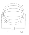
- the shape memory material 8 is filiform and extends along the entire length of the flexible membrane 6; in particular a plurality of wires is envisaged, which are made of the shape memory material 8 and are uniformly distributed along the flexible membrane 6. Upon application of an external influence of a physical nature the shape memory material 8 contracts, shortening and consequently deforming the flexible membrane 6 and therefore varying the volume of the pumping chamber 2.
- the piloting device 9 applies heat to modify the geometry of the shape memory material 8 and, in particular, the piloting device 9 circulates an electric current through the shape memory material 8 to heat the shape memory material 8 itself by Joule effect.
- the heating of the shape memory material 8 occurs by means of a phenomenon of magnetic or electromagnetic nature, or the shape memory material 8 is heated by a hot fluid.
- the shape memory material 8 is buried in the flexible membrane 6; in particular the flexible membrane 6 is made of pressed plastic material and the shape memory material 8 is co-pressed inside the flexible membrane 6.
- the shape memory material 8 is cyclically crossed by an impulsive electric current, which by the Joule effect determines the heating of the shape memory material 8 itself; following the heating, the shape memory material 8 contracts, shortening and determining a deformation of the flexible membrane 6 which causes a variation in the volume of the pumping chamber 2.
- the electric current passing through the shape memory material 8 is interrupted and the shape memory material 8 itself cools returning to its original length and determining a new deformation in the flexible membrane 6 equal and opposite to the previous deformation.
- the cyclical alternation of the deformations of the flexible membrane 6 determines a cyclical variation in the volume of the pumping chamber 2 and therefore actuates the fuel pumping.
- Regulating the frequency and/or the intensity of the physical influence applied to the shape memory material 8 it is possible to regulate the average capacity of the fuel pump 1 in an extremely simple and precise manner; in particular by increasing the frequency and/or intensity of the physical influence applied to the shape memory material 8 the average capacity of the fuel pump 1 is increased and vice versa.
- the shape memory material 8 transmits the heat to the surrounding flexible membrane 6, which is maintained at room temperature by the fuel that continually flows through the pumping chamber 2 and which wets an internal wall 10 of the flexible membrane 6 itself.
- the fuel pump 1 comprises a plurality of pumping chambers 2; moreover, one pumping chamber 2 could comprise two or more flexible membranes 6, each of which is coupled with a corresponding actuator device 7.
- the shape memory material 8 is "two-way”, i.e. it shortens when heated and lengthens spontaneously returning to its original dimensions when cooled.
- the shape memory material 8 could be "one-way”, i.e. it shortens when heated, but does not lengthen spontaneously returning to its original dimensions when cooled; in this case the lengthening of the shape memory material 8 when cooled is determined by the force of the spring-back of the flexible membrane 6.
- the fuel pump 1 described above presents numerous advantages, since it is simple and easy to construct and has at the same time a highly reduced size and a high level of energetic efficiency.
- the actuation of the fuel pump 1 described above is completely independent from the motion of the engine shaft and therefore the positioning and the fitting of the fuel pump 1 itself is extremely simple.
- the fuel pump 1 described above may be activated with a very higher frequency than the rotation of the engine shaft; therefore the pressure of the fuel downstream the fuel pump 1 presents extremely limited oscillations.
- by regulating the frequency and/or intensity of the physical influence applied to the shape memory material 8 it is possible to regulate the average capacity of the fuel pump 1 in an extremely simple and precise manner.
- the fuel pump 1 described above can be used both as a low pressure fuel pump and as a high pressure fuel pump.
Landscapes
- Engineering & Computer Science (AREA)
- Mechanical Engineering (AREA)
- General Engineering & Computer Science (AREA)
- Chemical & Material Sciences (AREA)
- Combustion & Propulsion (AREA)
- Reciprocating Pumps (AREA)
Priority Applications (1)
| Application Number | Priority Date | Filing Date | Title |
|---|---|---|---|
| EP06425042A EP1813803A1 (fr) | 2006-01-30 | 2006-01-30 | Pompe à carburant entraîné par un matériau à mémoire de forme |
Applications Claiming Priority (1)
| Application Number | Priority Date | Filing Date | Title |
|---|---|---|---|
| EP06425042A EP1813803A1 (fr) | 2006-01-30 | 2006-01-30 | Pompe à carburant entraîné par un matériau à mémoire de forme |
Publications (1)
| Publication Number | Publication Date |
|---|---|
| EP1813803A1 true EP1813803A1 (fr) | 2007-08-01 |
Family
ID=36607355
Family Applications (1)
| Application Number | Title | Priority Date | Filing Date |
|---|---|---|---|
| EP06425042A Withdrawn EP1813803A1 (fr) | 2006-01-30 | 2006-01-30 | Pompe à carburant entraîné par un matériau à mémoire de forme |
Country Status (1)
| Country | Link |
|---|---|
| EP (1) | EP1813803A1 (fr) |
Cited By (4)
| Publication number | Priority date | Publication date | Assignee | Title |
|---|---|---|---|---|
| CN104564624A (zh) * | 2013-10-25 | 2015-04-29 | 埃贝斯佩歇气候控制系统有限责任两合公司 | 特别是用于为车辆加热器输送液体燃料的泵 |
| WO2017102209A1 (fr) | 2015-12-17 | 2017-06-22 | Ksb Aktiengesellschaft | Pompe comportant un élément de refoulement déformable |
| WO2020087768A1 (fr) * | 2018-10-31 | 2020-05-07 | 李仕清 | Appareil électroménager à fonction haute/basse pression |
| CN112955657A (zh) * | 2018-10-31 | 2021-06-11 | 李仕清 | 一种具备高低压功能的家用电器 |
Citations (7)
| Publication number | Priority date | Publication date | Assignee | Title |
|---|---|---|---|---|
| US3606592A (en) * | 1970-05-20 | 1971-09-20 | Bendix Corp | Fluid pump |
| JPS6198980A (ja) * | 1984-10-19 | 1986-05-17 | Hitachi Ltd | 形状記憶合金を用いたポンプ装置 |
| JPH01170776A (ja) * | 1987-04-24 | 1989-07-05 | Mitsubishi Motors Corp | 燃料ポンプ構造 |
| US4846119A (en) * | 1987-08-15 | 1989-07-11 | Andreas Stihl | Fuel injection pump for a two-stroke engine |
| JP2001073906A (ja) * | 1999-09-06 | 2001-03-21 | Nissan Motor Co Ltd | 燃料噴射用高圧配管 |
| JP2001336443A (ja) * | 2000-05-26 | 2001-12-07 | Nissan Motor Co Ltd | ユニットインジェクタの制御装置 |
| EP1460260A2 (fr) * | 2003-03-19 | 2004-09-22 | Sofabex | Pompe à carburant électrique du type à membrane pour véhicule automobile |
-
2006
- 2006-01-30 EP EP06425042A patent/EP1813803A1/fr not_active Withdrawn
Patent Citations (7)
| Publication number | Priority date | Publication date | Assignee | Title |
|---|---|---|---|---|
| US3606592A (en) * | 1970-05-20 | 1971-09-20 | Bendix Corp | Fluid pump |
| JPS6198980A (ja) * | 1984-10-19 | 1986-05-17 | Hitachi Ltd | 形状記憶合金を用いたポンプ装置 |
| JPH01170776A (ja) * | 1987-04-24 | 1989-07-05 | Mitsubishi Motors Corp | 燃料ポンプ構造 |
| US4846119A (en) * | 1987-08-15 | 1989-07-11 | Andreas Stihl | Fuel injection pump for a two-stroke engine |
| JP2001073906A (ja) * | 1999-09-06 | 2001-03-21 | Nissan Motor Co Ltd | 燃料噴射用高圧配管 |
| JP2001336443A (ja) * | 2000-05-26 | 2001-12-07 | Nissan Motor Co Ltd | ユニットインジェクタの制御装置 |
| EP1460260A2 (fr) * | 2003-03-19 | 2004-09-22 | Sofabex | Pompe à carburant électrique du type à membrane pour véhicule automobile |
Non-Patent Citations (4)
| Title |
|---|
| PATENT ABSTRACTS OF JAPAN vol. 010, no. 277 (M - 519) 19 September 1986 (1986-09-19) * |
| PATENT ABSTRACTS OF JAPAN vol. 013, no. 446 (M - 877) 6 October 1989 (1989-10-06) * |
| PATENT ABSTRACTS OF JAPAN vol. 2000, no. 20 10 July 2001 (2001-07-10) * |
| PATENT ABSTRACTS OF JAPAN vol. 2002, no. 04 4 August 2002 (2002-08-04) * |
Cited By (9)
| Publication number | Priority date | Publication date | Assignee | Title |
|---|---|---|---|---|
| CN104564624A (zh) * | 2013-10-25 | 2015-04-29 | 埃贝斯佩歇气候控制系统有限责任两合公司 | 特别是用于为车辆加热器输送液体燃料的泵 |
| US20150118077A1 (en) * | 2013-10-25 | 2015-04-30 | Eberspächer Climate Control Systems GmbH & Co. KG | Pump, especially for delivering liquid fuel for a vehicle heater |
| RU2593870C2 (ru) * | 2013-10-25 | 2016-08-10 | Эбершпехер Клаймит Контрол Системз Гмбх Унд Ко. Кг | Насос, в частности, для подачи жидкого горючего материала для обогревателя транспортного средства |
| DE102013221744B4 (de) * | 2013-10-25 | 2019-05-16 | Eberspächer Climate Control Systems GmbH & Co. KG | Pumpe, insbesondere zum Fördern von flüssigem Brennstoff für ein Fahrzeugheizgerät |
| US10428808B2 (en) * | 2013-10-25 | 2019-10-01 | Eberspächer Climate Control Systems GmbH & Co. KG | Pump, especially for delivering liquid fuel for a vehicle heater |
| WO2017102209A1 (fr) | 2015-12-17 | 2017-06-22 | Ksb Aktiengesellschaft | Pompe comportant un élément de refoulement déformable |
| DE102015225726A1 (de) | 2015-12-17 | 2017-06-22 | Ksb Aktiengesellschaft | Pumpe mit verformbarem Förderelement |
| WO2020087768A1 (fr) * | 2018-10-31 | 2020-05-07 | 李仕清 | Appareil électroménager à fonction haute/basse pression |
| CN112955657A (zh) * | 2018-10-31 | 2021-06-11 | 李仕清 | 一种具备高低压功能的家用电器 |
Similar Documents
| Publication | Publication Date | Title |
|---|---|---|
| EP1813803A1 (fr) | Pompe à carburant entraîné par un matériau à mémoire de forme | |
| EP1598549B1 (fr) | Méthode d'injection directe de carburant dans un moteur à combustion interne | |
| US6976473B2 (en) | Fuel injection system for an internal combustion engine | |
| EP1269023A1 (fr) | Compresseur de gaz | |
| US10280907B2 (en) | Booster pump | |
| US20200271107A1 (en) | Drive system comprising at least one metal element exhibiting shape memory properties | |
| US7185491B2 (en) | Steam engine | |
| JP4528821B2 (ja) | 燃料供給装置のコントローラ | |
| US20110076160A1 (en) | Control device for a hydraulic piston machine with a variable flow rate | |
| CN107366585B (zh) | 用于控制适于直接喷射系统的燃料泵的方法 | |
| EP3513073A2 (fr) | Pompe volumétrique et système de commande | |
| CN110207415B (zh) | 用于维勒米尔热泵的四过程循环 | |
| WO2017145804A1 (fr) | Dispositif d'ajustement pour moteur stirling | |
| TW201239206A (en) | Hydraulic drive | |
| JP2008190483A (ja) | 外燃機関 | |
| JP6417971B2 (ja) | 吸入調量弁 | |
| WO2012175800A2 (fr) | Système d'injection de carburant | |
| JP2003269287A (ja) | 高圧燃料供給システム | |
| JP5792589B2 (ja) | 圧力制御装置および燃料供給装置 | |
| CN213039381U (zh) | 一种发动机电控燃油喷射系统 | |
| JP5866225B2 (ja) | 油圧ポンプ、特に燃料ポンプ | |
| CN111502950B (zh) | 一种高效高精度的直线液压泵双向配流方法 | |
| MX2015005905A (es) | Bomba para fluidos. | |
| US11162478B2 (en) | Hydraulic transmission for a SMA engine used in an energy recovery device | |
| JP7025997B2 (ja) | パルセーションダンパ |
Legal Events
| Date | Code | Title | Description |
|---|---|---|---|
| PUAI | Public reference made under article 153(3) epc to a published international application that has entered the european phase |
Free format text: ORIGINAL CODE: 0009012 |
|
| AK | Designated contracting states |
Kind code of ref document: A1 Designated state(s): AT BE BG CH CY CZ DE DK EE ES FI FR GB GR HU IE IS IT LI LT LU LV MC NL PL PT RO SE SI SK TR |
|
| AX | Request for extension of the european patent |
Extension state: AL BA HR MK YU |
|
| AKX | Designation fees paid | ||
| REG | Reference to a national code |
Ref country code: DE Ref legal event code: 8566 |
|
| STAA | Information on the status of an ep patent application or granted ep patent |
Free format text: STATUS: THE APPLICATION IS DEEMED TO BE WITHDRAWN |
|
| 18D | Application deemed to be withdrawn |
Effective date: 20080202 |