EP1811631A2 - Surface permanent magnet type rotating electric machine and manufacturing method thereof - Google Patents
Surface permanent magnet type rotating electric machine and manufacturing method thereof Download PDFInfo
- Publication number
- EP1811631A2 EP1811631A2 EP07100747A EP07100747A EP1811631A2 EP 1811631 A2 EP1811631 A2 EP 1811631A2 EP 07100747 A EP07100747 A EP 07100747A EP 07100747 A EP07100747 A EP 07100747A EP 1811631 A2 EP1811631 A2 EP 1811631A2
- Authority
- EP
- European Patent Office
- Prior art keywords
- scattering
- prevention tube
- permanent magnet
- electric machine
- rotating electric
- Prior art date
- Legal status (The legal status is an assumption and is not a legal conclusion. Google has not performed a legal analysis and makes no representation as to the accuracy of the status listed.)
- Granted
Links
Images


Classifications
-
- H—ELECTRICITY
- H02—GENERATION; CONVERSION OR DISTRIBUTION OF ELECTRIC POWER
- H02K—DYNAMO-ELECTRIC MACHINES
- H02K1/00—Details of the magnetic circuit
- H02K1/02—Details of the magnetic circuit characterised by the magnetic material
-
- B—PERFORMING OPERATIONS; TRANSPORTING
- B22—CASTING; POWDER METALLURGY
- B22F—WORKING METALLIC POWDER; MANUFACTURE OF ARTICLES FROM METALLIC POWDER; MAKING METALLIC POWDER; APPARATUS OR DEVICES SPECIALLY ADAPTED FOR METALLIC POWDER
- B22F7/00—Manufacture of composite layers, workpieces, or articles, comprising metallic powder, by sintering the powder, with or without compacting wherein at least one part is obtained by sintering or compression
- B22F7/008—Manufacture of composite layers, workpieces, or articles, comprising metallic powder, by sintering the powder, with or without compacting wherein at least one part is obtained by sintering or compression characterised by the composition
-
- H—ELECTRICITY
- H01—ELECTRIC ELEMENTS
- H01F—MAGNETS; INDUCTANCES; TRANSFORMERS; SELECTION OF MATERIALS FOR THEIR MAGNETIC PROPERTIES
- H01F7/00—Magnets
- H01F7/02—Permanent magnets [PM]
Definitions
- the present invention relates to a surface permanent magnet type rotating electric machine and a manufacturing method thereof, and more particularly to a surface permanent magnet type rotating electric machine having a scattering-prevention tube for suppressing scattering of a magnet arranged in a rotor and a manufacturing method thereof.
- Patent Document 1 discloses suppression of eddy current loss by dividing a scattering-prevention tube in a plurality of pieces in an axial direction to obtain a plurality of holding rings, in a motor provided with the scattering-prevention tube made of titanium around an outer circumference of a permanent magnet included in a rotor.
- Patent Document 2 discloses use of a titanium tube of high-strength as a tubular member provided around an outer circumference of a magnet of a rotor.
- Patent Document 3 discloses a high-strength titanium-based composite material in which TiB is dispersed.
- Patent Document 4 discloses lowering of eddy current loss by providing a slit in a metal cover provided around an outer circumference of a permanent magnet.
- Patent Document 5 discloses a titanium alloy composite material containing SiC particles.
- Japanese Utility-Model Laying-Open No. 07-020048 Patent Document 6
- Japanese Utility-Model Laying-Open No. 07-020049 Patent Document 7
- Japanese Utility-Model Laying-Open No. 07-020051 Patent Document 8
- Japanese Patent Laying-Open No. 10-225032 Patent Document 9
- Patent Document 10 discloses improvement in centrifugal fracture strength for withstanding ultrafast rotation, by covering a hollow rotation shaft made of metal with a hollow cylinder made of a composite material having high elasticity and high tensile strength.
- Patent Document 11 discloses a rotor formed by alternately layering a plurality of permanent magnets and a plurality of insulating materials in a direction of an axis of a rotation shaft.
- a tube for preventing the magnet from scattering is required to have high rigidity, low specific gravity, non-magnetic characteristic, and high specific resistance. If a motor is driven in high-speed rotation, magnetic field is switched at high frequency and eddy current is generated. Here, if the scattering-prevention tube has low specific resistance, the eddy current becomes greater and an amount of heat generation is increased, which results in increase in loss caused by heat.
- the scattering-prevention tube is made from carbon fibers, the requirements above are met to some extent, however, the cost increases. Meanwhile, if the scattering-prevention tube is made from a single type of metal, the requirements above cannot necessarily sufficiently be met.
- An object of the present invention is to provide a surface permanent magnet type rotating electric machine achieving suppressed eddy current loss while suppressing a complicated assembly step, and a manufacturing method thereof
- a surface permanent magnet type rotating electric machine in one aspect, includes a rotor.
- the rotor includes a magnet and a scattering-prevention tube provided around an outer circumference of the magnet and suppressing scattering of the magnet.
- the scattering-prevention tube is formed by sintering a composite material including a basis containing a non-magnetic high-strength material and particles having specific resistance higher than that of the basis containing the high-strength material.
- the scattering-prevention tube having high specific resistance is formed and eddy current loss is suppressed.
- higher specific resistance can be achieved without dividing the scattering-prevention tube, a complicated assembly operation of the scattering-prevention tube can be suppressed.
- a surface permanent magnet type rotating electric machine in another aspect, includes a rotor.
- the rotor includes a magnet and a scattering-prevention tube provided around an outer circumference of the magnet and suppressing scattering of the magnet.
- the scattering-prevention tube is formed by sintering a composite material obtained by layering, alternately in an axial direction, a layer containing a non-magnetic high-strength material and a layer having specific resistance higher than that of the layer containing the high-strength material.
- a method of manufacturing a surface permanent magnet type rotating electric machine includes the steps of: forming a composite material by mixing a basis containing a non-magnetic high-strength material and particles having specific resistance higher than that of the basis containing the high-strength material; forming a scattering-prevention tube by sintering the composite material; and forming a rotor by inserting a magnet in the scattering-prevention tube.
- the scattering-prevention tube having high specific resistance is formed and eddy current loss is suppressed.
- higher specific resistance can be achieved without dividing the scattering-prevention tube, a complicated assembly operation of the scattering-prevention tube can be suppressed.
- a method of manufacturing a surface permanent magnet type rotating electric machine includes the steps of: forming a composite material by alternately layering a layer containing a non-magnetic high-strength material and a layer having specific resistance higher than that of the layer containing the high-strength material; forming a scattering-prevention tube by sintering the composite material; and forming a rotor by inserting a magnet in the scattering-prevention tube.
- the basis containing the non-magnetic high-strength material is titanium
- the layer containing the non-magnetic high-strength material is a titanium layer.
- a surface permanent magnet type rotating electric machine achieving suppressed eddy current loss while suppressing a complicated assembly step, and a manufacturing method thereof can be obtained.
- Fig. 1 is a cross-sectional view of a surface permanent magnet type rotating electric machine according to one embodiment of the present invention.
- Fig. 2 is a cross-sectional view of a rotor in the surface permanent magnet type rotating electric machine according to the present embodiment.
- a surface permanent magnet type motor 300 according to the present embodiment includes a rotor 310, a stator 320, a housing 330, a rotation shaft 340, and a bearing 350.
- Rotor 310 and stator 320 are provided in housing 330.
- Rotor 310 is provided and fixed on rotation shaft 340.
- Rotation shaft 340 is supported by bearing 350 in a manner rotatable with respect to housing 330.
- rotor 310 includes a magnet 311 and a scattering-prevention tube 312 provided on an outer circumferential side of magnet 311.
- Scattering-prevention tube 312 is a tubular member for preventing breakage or scattering of magnet 311.
- surface permanent magnet type motor 300 representing the "surface permanent magnet type rotating electric machine” is a motor having rotor 310 in which magnet 311 is arranged around an outer circumferential surface of rotation shaft 340.
- Stator 320 includes a ring-shaped stator core 321 and a stator coil 322 wound around stator core 321.
- Stator core 321 is formed, for example, by layering plate-shaped magnetic elements made from iron, iron alloy, or the like.
- scattering-prevention tube 312 preferably has a high specific resistance characteristic.
- scattering-prevention tube 312 constituting rotor 310 is formed by sintering a composite material containing titanium serving as the "basis containing the non-magnetic high-strength material" and particles having specific resistance higher than that of titanium.
- scattering-prevention tube 312 as compared with scattering-prevention tube 312 formed from titanium alone, scattering-prevention tube 312 can have higher specific resistance, and therefore increase in the eddy current generated in scattering-prevention tube 312 can be suppressed. Consequently, heat generation is suppressed and loss caused by heat is reduced. As a result, surface permanent magnet type motor 300 adapted to high rotational speed can be obtained.
- silicon particles or the like may be used as the "particles having specific resistance higher than that of titanium.”
- a titanium alloy or a nickel alloy may be used as the "basis containing the high-strength material.”
- Fig. 3 is a cross-sectional view of rotor 310 in a variation of surface permanent magnet type motor 300 according to the present embodiment.
- rotor 310 includes magnet 311 and scattering-prevention tube 312 provided on the outer circumferential side of magnet 311.
- scattering-prevention tube 312 constituting rotor 310 is formed by sintering a composite material obtained by layering, alternately in an axial direction, a first portion 312A which is a titanium layer (layer containing the non-magnetic high-strength material) and a second portion 312B which is a layer having specific resistance higher than that of the titanium layer.
- scattering-prevention tube 312 as compared with scattering-prevention tube 312 formed from titanium alone, a flow path of eddy current I can be divided at second portion 312B, and therefore increase in the eddy current generated in scattering-prevention tube 312 can be suppressed. Consequently, heat generation is suppressed and loss caused by heat is reduced.
- Surface permanent magnet type motor 300 adapted to high rotational speed can thus be obtained.
- a layer containing silicon particles or the like may be used as the "layer having specific resistance higher than that of the titanium layer.”
- a titanium alloy layer or a nickel alloy layer may be used as the "layer containing the high-strength material.”
- FIG. 4 is a diagram illustrating a manufacturing process of scattering-prevention tube 312 shown in Fig. 2, while Fig. 5 is a diagram illustrating a manufacturing process of the scattering-prevention tube 312 shown in Fig. 3.
- titanium particles 3121 and silicon particles 3122 are poured into the same container, followed by mixing. Thereafter, sintering is performed, thereby obtaining scattering-prevention tube 312 containing silicon particles that are particles having specific resistance higher than that of titanium.
- the method of manufacturing surface permanent magnet type motor 300 shown in Fig. 2 includes the steps of forming the composite material by mixing titanium particles 3121 serving as the "basis containing the non-magnetic high-strength material" and silicon particles 3122 having specific resistance higher than that of titanium; forming scattering-prevention tube 312 by sintering the composite material (refer to Fig. 4 for these two steps); and forming rotor 310 by inserting magnet 311 in scattering-prevention tube 312 (Fig. 2).
- titanium particles 3120A are poured in the container and silicon particles 3120B are additionally poured. Further, titanium particles 3120A are additionally poured, thereby forming a layered structure of titanium particles 3120A and silicon particles 3120B.
- scattering-prevention tube 312 having a layered structure of first and second portions 312A and 312B can be obtained.
- the method of manufacturing surface permanent magnet type motor 300 shown in Fig. 3 includes the steps of: forming the composite material by alternately layering the layer of titanium particles 3120A (layer containing the non-magnetic high-strength material) and the layer containing silicon particles 3120B having specific resistance higher than that of titanium particles 3120A; forming scattering-prevention tube 312 by sintering the composite material (refer to Fig. 5 for these two steps); and forming rotor 310 by inserting magnet 311 in scattering-prevention tube 312 (Fig. 3).
- eddy current loss is suppressed as described above.
- the eddy current loss can be suppressed without dividing the scattering-prevention tube, the complicated assembly operation of the scattering-prevention tube can be suppressed.
- a surface permanent magnet type rotating electric machine includes a rotor (310).
- the rotor (310) has a magnet (311) and a scattering-prevention tube (312) provided around an outer circumference of the magnet (311) and suppressing scattering of the magnet (311).
- the scattering-prevention tube (312) is formed by sintering a titanium composite material obtained by layering, alternately in an axial direction, a first portion (312A) which is a titanium layer and a second portion (312B) having specific resistance higher than that of the first portion (312A).
Landscapes
- Engineering & Computer Science (AREA)
- Chemical & Material Sciences (AREA)
- Composite Materials (AREA)
- Manufacturing & Machinery (AREA)
- Materials Engineering (AREA)
- Mechanical Engineering (AREA)
- Power Engineering (AREA)
- Permanent Field Magnets Of Synchronous Machinery (AREA)
- Permanent Magnet Type Synchronous Machine (AREA)
- Manufacturing Cores, Coils, And Magnets (AREA)
Abstract
Description
- This nonprovisional application is based on
Japanese Patent Application No. 2006-012243 - The present invention relates to a surface permanent magnet type rotating electric machine and a manufacturing method thereof, and more particularly to a surface permanent magnet type rotating electric machine having a scattering-prevention tube for suppressing scattering of a magnet arranged in a rotor and a manufacturing method thereof.
- For example,
Japanese Patent Laying-Open No. 2001-169487 - In addition,
Japanese National Patent Publication No. 2001-513315 - Moreover,
Japanese Patent Laying-Open No. 05-239507 - Further,
Japanese Patent Laying-Open No. 2000-060042 - In addition,
Japanese Patent Laying-Open No. 05-005138 - In addition,
Japanese Utility-Model Laying-Open No. 07-020048 Japanese Utility-Model Laying-Open No. 07-020049 Japanese Utility-Model Laying-Open No. 07-020051 Japanese Patent Laying-Open No. 10-225032 - Moreover,
Japanese Patent Laying-Open No. 2002-303257 - Further,
Japanese Patent Laying-Open No. 2004-180349 - A tube for preventing the magnet from scattering is required to have high rigidity, low specific gravity, non-magnetic characteristic, and high specific resistance. If a motor is driven in high-speed rotation, magnetic field is switched at high frequency and eddy current is generated. Here, if the scattering-prevention tube has low specific resistance, the eddy current becomes greater and an amount of heat generation is increased, which results in increase in loss caused by heat.
- On the other hand, if the scattering-prevention tube is made from carbon fibers, the requirements above are met to some extent, however, the cost increases. Meanwhile, if the scattering-prevention tube is made from a single type of metal, the requirements above cannot necessarily sufficiently be met.
- In addition, if the scattering-prevention tube is divided into a plurality of holding rings as described in
Patent Document 1, the assembly step becomes complicated. - The requirements above cannot necessarily sufficiently be met either, with the structure described in Patent Documents 2 to 11.
- An object of the present invention is to provide a surface permanent magnet type rotating electric machine achieving suppressed eddy current loss while suppressing a complicated assembly step, and a manufacturing method thereof
- A surface permanent magnet type rotating electric machine according to the present invention, in one aspect, includes a rotor. The rotor includes a magnet and a scattering-prevention tube provided around an outer circumference of the magnet and suppressing scattering of the magnet. The scattering-prevention tube is formed by sintering a composite material including a basis containing a non-magnetic high-strength material and particles having specific resistance higher than that of the basis containing the high-strength material.
- According to the structure above, the scattering-prevention tube having high specific resistance is formed and eddy current loss is suppressed. In addition, as higher specific resistance can be achieved without dividing the scattering-prevention tube, a complicated assembly operation of the scattering-prevention tube can be suppressed.
- A surface permanent magnet type rotating electric machine according to the present invention, in another aspect, includes a rotor. The rotor includes a magnet and a scattering-prevention tube provided around an outer circumference of the magnet and suppressing scattering of the magnet. The scattering-prevention tube is formed by sintering a composite material obtained by layering, alternately in an axial direction, a layer containing a non-magnetic high-strength material and a layer having specific resistance higher than that of the layer containing the high-strength material.
- According to the structure above, as a flow path of an eddy current can be divided at the layer having high specific resistance, eddy current loss can be suppressed. In addition, as the flow path of the eddy current can be divided without dividing the scattering-prevention tube, a complicated assembly operation of the scattering-prevention tube can be suppressed.
- A method of manufacturing a surface permanent magnet type rotating electric machine according to the present invention, in one aspect, includes the steps of: forming a composite material by mixing a basis containing a non-magnetic high-strength material and particles having specific resistance higher than that of the basis containing the high-strength material; forming a scattering-prevention tube by sintering the composite material; and forming a rotor by inserting a magnet in the scattering-prevention tube.
- According to the method above, the scattering-prevention tube having high specific resistance is formed and eddy current loss is suppressed. In addition, as higher specific resistance can be achieved without dividing the scattering-prevention tube, a complicated assembly operation of the scattering-prevention tube can be suppressed.
- A method of manufacturing a surface permanent magnet type rotating electric machine according to the present invention, in another aspect, includes the steps of: forming a composite material by alternately layering a layer containing a non-magnetic high-strength material and a layer having specific resistance higher than that of the layer containing the high-strength material; forming a scattering-prevention tube by sintering the composite material; and forming a rotor by inserting a magnet in the scattering-prevention tube.
- According to the method above, as a flow path of an eddy current can be divided at the layer having high specific resistance, eddy current loss can be suppressed. In addition, as the flow path of the eddy current can be divided without dividing the scattering-prevention tube, a complicated assembly operation of the scattering-prevention tube can be suppressed.
- In the surface permanent magnet type rotating electric machine and the method of manufacturing a surface permanent magnet type rotating electric machine above, for example, the basis containing the non-magnetic high-strength material is titanium, and the layer containing the non-magnetic high-strength material is a titanium layer.
- According to the present invention, as described above, a surface permanent magnet type rotating electric machine achieving suppressed eddy current loss while suppressing a complicated assembly step, and a manufacturing method thereof can be obtained.
- The foregoing and other objects, features, aspects and advantages of the present invention will become more apparent from the following detailed description of the present invention when taken in conjunction with the accompanying drawings.
-
- Fig. 1 is a cross-sectional view of a surface permanent magnet type rotating electric machine according to one embodiment of the present invention.
- Fig. 2 is a cross-sectional view of a rotor in the surface permanent magnet type rotating electric machine according to one embodiment of the present invention.
- Fig. 3 is a cross-sectional view of a rotor in a variation of the surface permanent magnet type rotating electric machine according to one embodiment of the present invention.
- Fig. 4 illustrates a manufacturing process of a scattering-prevention tube in the surface permanent magnet type rotating electric machine according to one embodiment of the present invention.
- Fig. 5 illustrates a manufacturing process of a scattering-prevention tube in the variation of the surface permanent magnet type rotating electric machine according to one embodiment of the present invention.
- An embodiment of a surface permanent magnet type rotating electric machine and a manufacturing method thereof according to the present invention will be described hereinafter. The same or corresponding elements have the same reference characters allotted and detailed description thereof will not be repeated.
- Fig. 1 is a cross-sectional view of a surface permanent magnet type rotating electric machine according to one embodiment of the present invention. Fig. 2 is a cross-sectional view of a rotor in the surface permanent magnet type rotating electric machine according to the present embodiment. Referring to Fig. 1, a surface permanent
magnet type motor 300 according to the present embodiment includes arotor 310, astator 320, ahousing 330, arotation shaft 340, and abearing 350.Rotor 310 andstator 320 are provided inhousing 330.Rotor 310 is provided and fixed onrotation shaft 340.Rotation shaft 340 is supported by bearing 350 in a manner rotatable with respect tohousing 330. - As shown in Figs. 1 and 2,
rotor 310 includes amagnet 311 and a scattering-prevention tube 312 provided on an outer circumferential side ofmagnet 311. Scattering-prevention tube 312 is a tubular member for preventing breakage or scattering ofmagnet 311. As described above, surface permanentmagnet type motor 300 representing the "surface permanent magnet type rotating electric machine" is amotor having rotor 310 in whichmagnet 311 is arranged around an outer circumferential surface ofrotation shaft 340. - Stator 320 includes a ring-
shaped stator core 321 and astator coil 322 wound aroundstator core 321.Stator core 321 is formed, for example, by layering plate-shaped magnetic elements made from iron, iron alloy, or the like. - When
rotor 310 rotates at high speed (for example, at approximately 200,000 rpm), centrifugal force applied tomagnet 311 located in the vicinity of a side surface of the rotor (for example, having a diameter of approximately 20mm) becomes greater. Therefore, the following characteristics are required in scattering-prevention tube 312: - 1. High-rigidity; for ensuring strength for withstanding centrifugal force;
- 2. Low specific gravity; if specific gravity is high, the scattering-prevention tube itself is expanded due to centrifugal force and magnet fastening property is lowered;
- 3. Non-magnetic characteristic; the scattering-prevention tube is present in a gap portion between the magnet and the core; and
- 4. High specific resistance; for lowering eddy current loss.
- If
rotor 310 rotates at high speed, the magnetic field is switched at high frequency and eddy current I is generated in scattering-prevention tube 312 as shown in Fig. 2. If the eddy current becomes greater, heat is generated, which affects drive power of the motor. Therefore, scattering-prevention tube 312 preferably has a high specific resistance characteristic. - In surface permanent
magnet type motor 300 according to the present embodiment, scattering-prevention tube 312 constitutingrotor 310 is formed by sintering a composite material containing titanium serving as the "basis containing the non-magnetic high-strength material" and particles having specific resistance higher than that of titanium. By thus forming scattering-prevention tube 312, as compared with scattering-prevention tube 312 formed from titanium alone, scattering-prevention tube 312 can have higher specific resistance, and therefore increase in the eddy current generated in scattering-prevention tube 312 can be suppressed. Consequently, heat generation is suppressed and loss caused by heat is reduced. As a result, surface permanentmagnet type motor 300 adapted to high rotational speed can be obtained. - For example, silicon particles or the like may be used as the "particles having specific resistance higher than that of titanium." In addition, a titanium alloy or a nickel alloy may be used as the "basis containing the high-strength material."
- Fig. 3 is a cross-sectional view of
rotor 310 in a variation of surface permanentmagnet type motor 300 according to the present embodiment. Referring to Fig. 3, in this variation as well,rotor 310 includesmagnet 311 and scattering-prevention tube 312 provided on the outer circumferential side ofmagnet 311. - In surface permanent
magnet type motor 300 according to this variation, scattering-prevention tube 312 constitutingrotor 310 is formed by sintering a composite material obtained by layering, alternately in an axial direction, afirst portion 312A which is a titanium layer (layer containing the non-magnetic high-strength material) and asecond portion 312B which is a layer having specific resistance higher than that of the titanium layer. By thus forming scattering-prevention tube 312, as compared with scattering-prevention tube 312 formed from titanium alone, a flow path of eddy current I can be divided atsecond portion 312B, and therefore increase in the eddy current generated in scattering-prevention tube 312 can be suppressed. Consequently, heat generation is suppressed and loss caused by heat is reduced. Surface permanentmagnet type motor 300 adapted to high rotational speed can thus be obtained. - For example, a layer containing silicon particles or the like may be used as the "layer having specific resistance higher than that of the titanium layer." In addition, a titanium alloy layer or a nickel alloy layer may be used as the "layer containing the high-strength material."
- A manufacturing process of
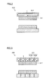
rotor 310 described above will now be described. Fig. 4 is a diagram illustrating a manufacturing process of scattering-prevention tube 312 shown in Fig. 2, while Fig. 5 is a diagram illustrating a manufacturing process of the scattering-prevention tube 312 shown in Fig. 3. - Referring to Fig. 4,
titanium particles 3121 andsilicon particles 3122 are poured into the same container, followed by mixing. Thereafter, sintering is performed, thereby obtaining scattering-prevention tube 312 containing silicon particles that are particles having specific resistance higher than that of titanium. - Namely, the method of manufacturing surface permanent
magnet type motor 300 shown in Fig. 2 includes the steps of forming the composite material by mixingtitanium particles 3121 serving as the "basis containing the non-magnetic high-strength material" andsilicon particles 3122 having specific resistance higher than that of titanium; forming scattering-prevention tube 312 by sintering the composite material (refer to Fig. 4 for these two steps); and formingrotor 310 by insertingmagnet 311 in scattering-prevention tube 312 (Fig. 2). - Referring to Fig. 5,
titanium particles 3120A are poured in the container andsilicon particles 3120B are additionally poured. Further,titanium particles 3120A are additionally poured, thereby forming a layered structure oftitanium particles 3120A andsilicon particles 3120B. By performing sintering in this state, scattering-prevention tube 312 having a layered structure of first andsecond portions - Namely, the method of manufacturing surface permanent
magnet type motor 300 shown in Fig. 3 includes the steps of: forming the composite material by alternately layering the layer oftitanium particles 3120A (layer containing the non-magnetic high-strength material) and the layer containingsilicon particles 3120B having specific resistance higher than that oftitanium particles 3120A; forming scattering-prevention tube 312 by sintering the composite material (refer to Fig. 5 for these two steps); and formingrotor 310 by insertingmagnet 311 in scattering-prevention tube 312 (Fig. 3). - According to the surface permanent magnet type rotating electric machine and the manufacturing method thereof in the present embodiment, eddy current loss is suppressed as described above. In addition, as the eddy current loss can be suppressed without dividing the scattering-prevention tube, the complicated assembly operation of the scattering-prevention tube can be suppressed.
- Although the present invention has been described and illustrated in detail, it is clearly understood that the same is by way of illustration and example only and is not to be taken by way of limitation, the spirit and scope of the present invention being limited only by the terms of the appended claims.
- A surface permanent magnet type rotating electric machine includes a rotor (310). The rotor (310) has a magnet (311) and a scattering-prevention tube (312) provided around an outer circumference of the magnet (311) and suppressing scattering of the magnet (311). The scattering-prevention tube (312) is formed by sintering a titanium composite material obtained by layering, alternately in an axial direction, a first portion (312A) which is a titanium layer and a second portion (312B) having specific resistance higher than that of the first portion (312A).
Claims (8)
- A surface permanent magnet type rotating electric machine comprising a rotor (310);
said rotor (310) including a magnet (311) and a scattering-prevention tube (312) provided around an outer circumference of said magnet (311) and suppressing scattering of said magnet (311), and
said scattering-prevention tube (312) being formed by sintering a composite material including a basis (3121) containing a non-magnetic high-strength material and particles (3122) having specific resistance higher than that of said basis (3121) containing the high-strength material. - The surface permanent magnet type rotating electric machine according to claim 1, wherein
said basis (3121) containing said high-strength material is titanium. - A surface permanent magnet type rotating electric machine comprising a rotor (310);
said rotor (310) including a magnet (311) and a scattering-prevention tube (312) provided around an outer circumference of said magnet (311) and suppressing scattering of said magnet (311), and
said scattering-prevention tube (312) being formed by sintering a composite material obtained by layering, alternately in an axial direction, a layer (312A) containing a non-magnetic high-strength material (3120A) and a layer (312B) having specific resistance higher than that of the layer (312A) containing the high-strength material (3120A). - The surface permanent magnet type rotating electric machine according to claim 3, wherein
said layer (312A) containing said high-strength material (3120A) is a titanium layer. - A method of manufacturing a surface permanent magnet type rotating electric machine, comprising the steps of:forming a composite material by mixing a basis (3121) containing a non-magnetic high-strength material and particles (3122) having specific resistance higher than that of said basis (3121) containing the high-strength material;forming a scattering-prevention tube (312) by sintering said composite material; andforming a rotor (310) by inserting a magnet (311) in said scattering-prevention tube (312).
- The method of manufacturing a surface permanent magnet type rotating electric machine according to claim 5, wherein
said basis (3121) containing said high-strength material is titanium. - A method of manufacturing a surface permanent magnet type rotating electric machine, comprising the steps of:forming a composite material by alternately layering a layer (312A) containing a non-magnetic high-strength material (3120A) and a layer (312B) having specific resistance higher than that of the layer (312A) containing the high-strength material (3120A);forming a scattering-prevention tube (312) by sintering said composite material; andforming a rotor (310) by inserting a magnet (311) in said scattering-prevention tube (312).
- The method of manufacturing a surface permanent magnet type rotating electric machine according to claim 7, wherein
said layer (312A) containing said high-strength material (3120A) is a titanium layer.
Applications Claiming Priority (1)
| Application Number | Priority Date | Filing Date | Title |
|---|---|---|---|
| JP2006012243A JP4613833B2 (en) | 2006-01-20 | 2006-01-20 | Surface magnet type rotating electrical machine and method for manufacturing the same |
Publications (3)
| Publication Number | Publication Date |
|---|---|
| EP1811631A2 true EP1811631A2 (en) | 2007-07-25 |
| EP1811631A3 EP1811631A3 (en) | 2011-04-27 |
| EP1811631B1 EP1811631B1 (en) | 2012-12-19 |
Family
ID=38015893
Family Applications (1)
| Application Number | Title | Priority Date | Filing Date |
|---|---|---|---|
| EP20070100747 Active EP1811631B1 (en) | 2006-01-20 | 2007-01-18 | Surface permanent magnet type rotating electric machine and manufacturing method thereof |
Country Status (2)
| Country | Link |
|---|---|
| EP (1) | EP1811631B1 (en) |
| JP (1) | JP4613833B2 (en) |
Cited By (2)
| Publication number | Priority date | Publication date | Assignee | Title |
|---|---|---|---|---|
| US11043859B2 (en) | 2016-12-22 | 2021-06-22 | Meidensha Corporation | Permanent magnet rotating electric machine |
| US12341384B2 (en) | 2021-09-15 | 2025-06-24 | Drs Naval Power Systems, Inc. | Multi-metallic mechanical retention hoop |
Families Citing this family (2)
| Publication number | Priority date | Publication date | Assignee | Title |
|---|---|---|---|---|
| JP6332431B1 (en) * | 2016-12-22 | 2018-05-30 | 株式会社明電舎 | Permanent magnet rotating electric machine |
| JP6319416B1 (en) * | 2016-12-22 | 2018-05-09 | 株式会社明電舎 | Permanent magnet rotating electric machine |
Family Cites Families (6)
| Publication number | Priority date | Publication date | Assignee | Title |
|---|---|---|---|---|
| JPS49117918A (en) * | 1973-03-19 | 1974-11-11 | ||
| JP2847756B2 (en) * | 1989-06-06 | 1999-01-20 | いすゞ自動車株式会社 | Rotating electric machine rotor |
| JPH04300251A (en) * | 1991-03-28 | 1992-10-23 | Shin Etsu Chem Co Ltd | Method for manufacturing titanium boride sintered body |
| JPH09322450A (en) * | 1996-06-04 | 1997-12-12 | Toyota Motor Corp | Electric motor rotor |
| JPH10210692A (en) * | 1997-01-22 | 1998-08-07 | Matsushita Electric Ind Co Ltd | Permanent magnet rotor |
| US20030193258A1 (en) * | 2002-04-16 | 2003-10-16 | Reiter Frederick B. | Composite powder metal rotor sleeve |
-
2006
- 2006-01-20 JP JP2006012243A patent/JP4613833B2/en not_active Expired - Lifetime
-
2007
- 2007-01-18 EP EP20070100747 patent/EP1811631B1/en active Active
Cited By (2)
| Publication number | Priority date | Publication date | Assignee | Title |
|---|---|---|---|---|
| US11043859B2 (en) | 2016-12-22 | 2021-06-22 | Meidensha Corporation | Permanent magnet rotating electric machine |
| US12341384B2 (en) | 2021-09-15 | 2025-06-24 | Drs Naval Power Systems, Inc. | Multi-metallic mechanical retention hoop |
Also Published As
| Publication number | Publication date |
|---|---|
| JP2007195354A (en) | 2007-08-02 |
| JP4613833B2 (en) | 2011-01-19 |
| EP1811631A3 (en) | 2011-04-27 |
| EP1811631B1 (en) | 2012-12-19 |
Similar Documents
| Publication | Publication Date | Title |
|---|---|---|
| CN102460914B (en) | Motor rotor | |
| CN110971033B (en) | Motor | |
| EP2154766A1 (en) | Rotor and permanent magnet rotating electric machine | |
| EP1811631B1 (en) | Surface permanent magnet type rotating electric machine and manufacturing method thereof | |
| JP2008219965A (en) | Rotary machine | |
| JP2020065435A (en) | Magnetic flux shield for electric motor | |
| CN107579614A (en) | Rotor and high-speed permanent magnet motor | |
| WO2009058575A1 (en) | Stator lamination | |
| EP2568585A2 (en) | Manufacturing method of rotating electric machine and rotating electric machine | |
| JP4696900B2 (en) | Rotating electric machine | |
| US20080088195A1 (en) | Outside rotor electric machine | |
| JP4990599B2 (en) | Permanent magnet rotating electric machine | |
| JP2013188075A (en) | Rotor of permanent magnet type rotary electrical machine | |
| JP2008099479A (en) | Magnet-embedded type rotor in rotary electric machine, and the rotary electric machine using the same | |
| JP2010057233A (en) | Rotor structure of permanent magnet rotating electric machine | |
| CN101605998B (en) | Magnetic Bearing Unit | |
| JP2008301666A (en) | Axial motor | |
| WO2005011085A1 (en) | End ring support structure for electric motor | |
| KR20100005737A (en) | Motor stator for preventing reduction of permanent magnet | |
| JPH11332147A (en) | Permanent magnet rotating machine | |
| CN101868901B (en) | Laminations with tapered tooth geometry for use in electric motors | |
| JP4957891B2 (en) | Synchronous motor | |
| JP2017108585A (en) | Electric supercharged compressor | |
| US12438408B2 (en) | Induction motor | |
| WO2020017523A1 (en) | Embedded magnet type rotor, motor, and electrical appliance |
Legal Events
| Date | Code | Title | Description |
|---|---|---|---|
| PUAI | Public reference made under article 153(3) epc to a published international application that has entered the european phase |
Free format text: ORIGINAL CODE: 0009012 |
|
| 17P | Request for examination filed |
Effective date: 20070118 |
|
| AK | Designated contracting states |
Kind code of ref document: A2 Designated state(s): AT BE BG CH CY CZ DE DK EE ES FI FR GB GR HU IE IS IT LI LT LU LV MC NL PL PT RO SE SI SK TR |
|
| AX | Request for extension of the european patent |
Extension state: AL BA HR MK YU |
|
| PUAL | Search report despatched |
Free format text: ORIGINAL CODE: 0009013 |
|
| AK | Designated contracting states |
Kind code of ref document: A3 Designated state(s): AT BE BG CH CY CZ DE DK EE ES FI FR GB GR HU IE IS IT LI LT LU LV MC NL PL PT RO SE SI SK TR |
|
| AX | Request for extension of the european patent |
Extension state: AL BA HR MK RS |
|
| AKX | Designation fees paid |
Designated state(s): DE FR IT |
|
| GRAP | Despatch of communication of intention to grant a patent |
Free format text: ORIGINAL CODE: EPIDOSNIGR1 |
|
| GRAS | Grant fee paid |
Free format text: ORIGINAL CODE: EPIDOSNIGR3 |
|
| GRAA | (expected) grant |
Free format text: ORIGINAL CODE: 0009210 |
|
| AK | Designated contracting states |
Kind code of ref document: B1 Designated state(s): DE FR IT |
|
| REG | Reference to a national code |
Ref country code: DE Ref legal event code: R096 Ref document number: 602007027421 Country of ref document: DE Effective date: 20130221 |
|
| RAP2 | Party data changed (patent owner data changed or rights of a patent transferred) |
Owner name: TOYOTA JIDOSHA KABUSHIKI KAISHA |
|
| PLBE | No opposition filed within time limit |
Free format text: ORIGINAL CODE: 0009261 |
|
| STAA | Information on the status of an ep patent application or granted ep patent |
Free format text: STATUS: NO OPPOSITION FILED WITHIN TIME LIMIT |
|
| 26N | No opposition filed |
Effective date: 20130920 |
|
| REG | Reference to a national code |
Ref country code: DE Ref legal event code: R097 Ref document number: 602007027421 Country of ref document: DE Effective date: 20130920 |
|
| REG | Reference to a national code |
Ref country code: DE Ref legal event code: R084 Ref document number: 602007027421 Country of ref document: DE |
|
| REG | Reference to a national code |
Ref country code: DE Ref legal event code: R084 Ref document number: 602007027421 Country of ref document: DE Effective date: 20141021 |
|
| REG | Reference to a national code |
Ref country code: FR Ref legal event code: PLFP Year of fee payment: 10 |
|
| REG | Reference to a national code |
Ref country code: FR Ref legal event code: PLFP Year of fee payment: 11 |
|
| REG | Reference to a national code |
Ref country code: FR Ref legal event code: PLFP Year of fee payment: 12 |
|
| P01 | Opt-out of the competence of the unified patent court (upc) registered |
Effective date: 20230427 |
|
| PGFP | Annual fee paid to national office [announced via postgrant information from national office to epo] |
Ref country code: FR Payment date: 20251128 Year of fee payment: 20 |
|
| PGFP | Annual fee paid to national office [announced via postgrant information from national office to epo] |
Ref country code: DE Payment date: 20251203 Year of fee payment: 20 |
|
| PGFP | Annual fee paid to national office [announced via postgrant information from national office to epo] |
Ref country code: IT Payment date: 20251219 Year of fee payment: 20 |