EP1811231A2 - Chambre de combustion de moteur à turbine à gaz segmentée et refroidie par effusion - Google Patents
Chambre de combustion de moteur à turbine à gaz segmentée et refroidie par effusion Download PDFInfo
- Publication number
- EP1811231A2 EP1811231A2 EP07101064A EP07101064A EP1811231A2 EP 1811231 A2 EP1811231 A2 EP 1811231A2 EP 07101064 A EP07101064 A EP 07101064A EP 07101064 A EP07101064 A EP 07101064A EP 1811231 A2 EP1811231 A2 EP 1811231A2
- Authority
- EP
- European Patent Office
- Prior art keywords
- effusion cooling
- rows
- cooling holes
- combustor
- disposed
- Prior art date
- Legal status (The legal status is an assumption and is not a legal conclusion. Google has not performed a legal analysis and makes no representation as to the accuracy of the status listed.)
- Granted
Links
- 238000001816 cooling Methods 0.000 claims abstract description 140
- 238000010790 dilution Methods 0.000 claims description 28
- 239000012895 dilution Substances 0.000 claims description 28
- 238000011144 upstream manufacturing Methods 0.000 claims description 24
- 238000002485 combustion reaction Methods 0.000 claims description 11
- 230000001154 acute effect Effects 0.000 claims description 4
- 230000007704 transition Effects 0.000 abstract description 4
- 239000007789 gas Substances 0.000 description 14
- 239000000446 fuel Substances 0.000 description 8
- 230000003416 augmentation Effects 0.000 description 3
- 230000000712 assembly Effects 0.000 description 2
- 238000000429 assembly Methods 0.000 description 2
- 230000002411 adverse Effects 0.000 description 1
- 238000010276 construction Methods 0.000 description 1
- 239000000463 material Substances 0.000 description 1
- 239000011159 matrix material Substances 0.000 description 1
- 230000000116 mitigating effect Effects 0.000 description 1
- 239000000203 mixture Substances 0.000 description 1
- 238000012986 modification Methods 0.000 description 1
- 230000004048 modification Effects 0.000 description 1
Images


Classifications
-
- F—MECHANICAL ENGINEERING; LIGHTING; HEATING; WEAPONS; BLASTING
- F23—COMBUSTION APPARATUS; COMBUSTION PROCESSES
- F23R—GENERATING COMBUSTION PRODUCTS OF HIGH PRESSURE OR HIGH VELOCITY, e.g. GAS-TURBINE COMBUSTION CHAMBERS
- F23R3/00—Continuous combustion chambers using liquid or gaseous fuel
- F23R3/002—Wall structures
-
- F—MECHANICAL ENGINEERING; LIGHTING; HEATING; WEAPONS; BLASTING
- F23—COMBUSTION APPARATUS; COMBUSTION PROCESSES
- F23R—GENERATING COMBUSTION PRODUCTS OF HIGH PRESSURE OR HIGH VELOCITY, e.g. GAS-TURBINE COMBUSTION CHAMBERS
- F23R3/00—Continuous combustion chambers using liquid or gaseous fuel
- F23R3/02—Continuous combustion chambers using liquid or gaseous fuel characterised by the air-flow or gas-flow configuration
- F23R3/04—Air inlet arrangements
- F23R3/06—Arrangement of apertures along the flame tube
-
- F—MECHANICAL ENGINEERING; LIGHTING; HEATING; WEAPONS; BLASTING
- F23—COMBUSTION APPARATUS; COMBUSTION PROCESSES
- F23R—GENERATING COMBUSTION PRODUCTS OF HIGH PRESSURE OR HIGH VELOCITY, e.g. GAS-TURBINE COMBUSTION CHAMBERS
- F23R2900/00—Special features of, or arrangements for continuous combustion chambers; Combustion processes therefor
- F23R2900/03041—Effusion cooled combustion chamber walls or domes
-
- Y—GENERAL TAGGING OF NEW TECHNOLOGICAL DEVELOPMENTS; GENERAL TAGGING OF CROSS-SECTIONAL TECHNOLOGIES SPANNING OVER SEVERAL SECTIONS OF THE IPC; TECHNICAL SUBJECTS COVERED BY FORMER USPC CROSS-REFERENCE ART COLLECTIONS [XRACs] AND DIGESTS
- Y02—TECHNOLOGIES OR APPLICATIONS FOR MITIGATION OR ADAPTATION AGAINST CLIMATE CHANGE
- Y02T—CLIMATE CHANGE MITIGATION TECHNOLOGIES RELATED TO TRANSPORTATION
- Y02T50/00—Aeronautics or air transport
- Y02T50/60—Efficient propulsion technologies, e.g. for aircraft
Definitions
- the present invention relates to gas turbine engines and, more particularly, to a gas turbine engine combustor effusion cooling mechanism that improves combustor cooling efficiency.
- a gas turbine engine may be used to power various types of vehicles and systems.
- a particular type of gas turbine engine that may be used to power aircraft is a turbofan gas turbine engine.
- a turbofan gas turbine engine may include, for example, five major sections, a fan section, a compressor section, a combustor section, a turbine section, and an exhaust section.
- the fan section is positioned at the front, or "inlet” section of the engine, and includes a fan that induces air from the surrounding environment into the engine, and accelerates a fraction of this air toward the compressor section. The remaining fraction of air induced into the fan section is accelerated into and through a bypass plenum, and out the exhaust section.
- the compressor section raises the pressure of the air it receives from the fan section to a relatively high level.
- the compressor section may include two or more compressors, such as, for example, a high pressure compressor and a low pressure compressor.
- the compressed air from the compressor section then enters the combustor section, where a ring of fuel nozzles injects a steady stream of fuel into a plenum formed by combustor liners and a dome.
- the injected fuel is ignited in the combustor, which significantly increases the energy of the compressed air.
- the high-energy compressed air from the combustor section then flows into and through the turbine section, causing rotationally mounted turbine blades to rotate and generate energy.
- the air exiting the turbine section is exhausted from the engine via the exhaust section, and the energy remaining in the exhaust air aids the thrust generated by the air lowing through the bypass plenum.
- the combustors in gas turbine engines typically operate at relatively high temperatures (e.g., >3500°F). Such high temperatures can adversely impact the service life of a combustor. Thus, some form of cooling is typically provided for the combustor.
- combustor cooling is known as effusion cooling. Effusion cooling involves providing a matrix of relatively small diameter effusion cooling holes through the combustor liners, and into which a flow of cooling air is admitted. The effusion cooling holes are typically angled relative to a surface of the combustor. This angle increases the length of the effusion holes through the liners, which increases the surface area from which the cooling flow removes heat from the liner, and generates a cooling film on the inner wall of the liners.
- effusion cooling is generally effective, it does suffer certain drawbacks.
- one characteristic of effusion cooling is that the film effectiveness may be relatively low at or near upstream sections of the combustor liner.
- the cooling film once it is sufficiently established, may be interrupted by one or more rows of major combustor orifices, such as dilution holes.
- some form of cooling augmentation may be used in the upstream sections of effusion cooled combustor liners and/or at locations downstream of major combustor orifices. Such cooling augmentation can complicate the construction of combustor and increase overall size, weight, and/or costs.
- an effusion cooling configuration that eliminates, or at least reduces the likelihood of, the above-noted drawbacks. Namely, there is a need for an effusion cooling configuration that does not exhibit a relatively low film effectiveness at or near upstream sections of the combustor, and/or a configuration in which the cooling film that is established is not interrupted by one or more rows of major combustor orifices, and/or that does not rely on one or more forms of cooling augmentation.
- the present invention addresses one or more of these needs.
- a gas turbine engine combustor includes an inner liner, an outer liner, a dome assembly, and two or more sets of effusion cooling holes.
- the inner liner has an inner surface, an outer surface, an upstream end, and a downstream end, and extends in an axial direction between the upstream and downstream ends.
- the outer liner extends in the axial direction and has an inner surface, an outer surface, an upstream end, and a downstream end.
- the outer liner is spaced apart from, and at least partially surrounds, the inner liner
- the dome assembly is coupled between the upstream ends of the inner and outer annular liners to define a combustion chamber between the inner liner outer surface and the outer liner inner surface.
- the two or more sets of effusion cooling holes extend through the outer liner between the outer liner outer and inner surfaces.
- Each set of effusion cooling holes includes one or more initial rows of effusion cooling holes, one or more final rows of effusion cooling holes disposed downstream of the one or more initial rows, and a plurality of interposed rows of effusion cooling holes disposed between the initial and final rows.
- Each effusion cooling hole in the one or more initial rows is disposed at a tangential angle of between about 70° and about 90° relative to the axial direction.
- Each effusion cooling hole in the one or more final rows is disposed at a tangential angle of between about 0° and about 20° relative to the axial direction.
- Each effusion cooling hole in each of the interposed rows is disposed at a tangential angle, relative to the axial direction, that is less than the tangential angle of the effusion cooling holes in the one or more initial rows and greater than the tangential angle of the effusion cooling holes in the one or more final rows.
- a gas turbine engine combustor in another exemplary embodiment, includes an inner liner, an outer liner, a dome assembly, two or more sets of effusion cooling holes extending through the inner liner between the inner liner outer and inner surfaces, and two or more sets of effusion cooling holes extending through die outer liner between the outer liner outer and inner surfaces.
- the inner liner has an inner surface, an outer surface, an upstream end, and a downstream end, and extends in an axial direction between the upstream and downstream ends.
- the outer liner extends in the axial direction and has an inner surface, an outer surface, an upstream end, and a downstream end. The outer liner is spaced apart from, and at least partially surrounds, the inner liner.
- the dome assembly is coupled between the upstream ends of the inner and outer annular liners to define a combustion chamber between the inner liner outer surface and the outer liner inner surface.
- Each set of effusion cooling holes in both the inner and outer liners includes one or more initial rows of effusion cooling holes, one or more final rows of effusion cooling holes disposed downstream of the one or more initial rows, and a plurality of interposed rows of effusion cooling holes disposed between the initial and final rows.
- Each effusion cooling hole in the one or more initial rows is disposed at a tangential angle of between about 70° and about 90° relative to the axial direction.
- Each effusion cooling hole in the one or more final rows is disposed at a tangential angle of between about 0° and about 20° relative to the axial direction.
- Each effusion cooling hole in each of the interposed rows is disposed at a tangential angle, relative to the axial direction, that is less than the tangential angle of the effusion cooling holes in the one or more initial rows and greater than the tangential angle of the effusion cooling holes in the one or more final rows.
- a gas turbine engine includes a compressor, a turbine, and a combustor with an effusion cooling mechanism that improves combustor cooling efficiency.
- FIG. 1 is a simplified cross section side view of an exemplary multi-spool turbofan gas turbine jet engine according to an embodiment of the present invention
- FIGS. 2 and 3 are perspective views of an exemplary combustor according to an embodiment of the present invention, from an upstream end and a downstream end, respectively, that may be used in the engine of FIG. 1;
- FIG. 4 is a top view of a portion of an exemplary combustor liner according to an embodiment of the present invention that may be used to implement the combustor shown in FIGS. 2 and 3;
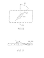
- FIG. 5 is a close-up view of the exemplary combustor liner shown in FIG. 4, depicting the configuration of an exemplary effusion cooling hole that extends therethrough;
- FIG. 6 is a cross section view of a portion of the exemplary combustor liner shown in FIG. 4, and which is taken along line 6-6 in FIG. 4.
- FIG. 1 An exemplary embodiment of a multi-spool turbofan gas turbine jet engine 100 is depicted in FIG. 1, and includes an intake section 102, a compressor section 104, a combustion section 106, a turbine section 108, and an exhaust section 110
- the intake section 102 includes a fan 112, which is mounted in a fan case 114.
- the fan 112 draws air into the intake section 102 and accelerates it.
- a fraction of the accelerated air exhausted from the fan 112 is directed through a bypass section 116 disposed between the fan case 114 and an engine cowl 118, and provides a forward thrust.
- the remaining fraction of air exhausted from the fan 112 is directed into the compressor section 104.
- the compressor section 104 includes two compressors, an intermediate pressure compressor 120, and a high pressure compressor 122.
- the intermediate pressure compressor 120 raises the pressure of the air directed into it from the fan 112, and directs the compressed air into the high pressure compressor 122.
- the high pressure compressor 122 compresses the air still further, and directs the high pressure air into the combustion section 106.
- section 106 the high pressure air is mixed with fuel and combusted in a combustor 124. The combusted air is then directed into the turbine section 108,
- the turbine section 108 includes three turbines disposed in axial flow series, a high pressure turbine 126, an intermediate pressure turbine 128, and a low pressure turbine 130.
- the combusted air from the combustion section 106 expands through each turbine, causing it to rotate.
- the air is then exhausted through a propulsion nozzle 132 disposed in the exhaust section 110, providing addition forward thrust.
- each drives equipment in the engine 100 via concentrically disposed shafts or spools.
- the high pressure turbine 126 drives the high pressure compressor 122 via a high pressure spool 134
- the intermediate pressure turbine 128 drives the intermediate pressure compressor 120 via an intermediate pressure spool 136
- the low pressure turbine 130 drives the fan 112 via a low pressure spool 138.
- the combustor 124 which in the depicted embodiment is implemented as an annular combustor, includes an inner liner 202, an outer liner 204, and a dome 206.
- the inner liner 202 includes an inner surface 208, an outer surface 212, an upstream end 214, and a downstream end 216.
- the outer liner 204 which at least partially surrounds the inner liner 202, includes an inner surface 218, an outer surface 222, an upstream end 224, and a downstream end 226.
- the dome 206 is coupled between the upstream ends 214 and 222 of the inner 202 and outer 204 liners, respectively, forming a combustion chamber 228 between the inner 202 and outer 204
- the inner 202 and outer liners 204 each include a circumferential row of dilution openings 234.
- the dilution openings 23 admit additional air into the combustion chamber 228 to establish combustor aerodynamics and cool the exhaust gases to acceptable levels before entering the turbine section 108.
- FIGS. 2 and 3 Only a single circumferential row of dilution openings 234 is depicted in FIGS. 2 and 3, it will be appreciated that the inner 202 and outer 204 liners could also be implemented with two or more circumferential rows of dilution openings 234.
- a combustor 124 is implemented with two or more circumferential rows of dilution openings 234, the upstream-most dilution openings 234 are referred to as primary dilution openings, and each subsequent downstream circumferential row of dilution openings 234 are referred to as secondary dilution openings.
- the dome 206 also includes a plurality of openings.
- a plurality of circumferentially spaced, axially facing swirler assembly openings 236 are formed in the dome 206.
- Each of the swirler assembly openings 236 is configured to have mounted therein a non-illustrated swirler assembly.
- the non-illustrated swirler assemblies each receive compressed air from the compressor section 104 and fuel from a non-illustrated fuel tube. The fuel and air are swirled and mixed in the swirler assemblies, and the fuel/air mixture is then discharged into the combustion chamber 228 where it is ignited by one or more non-illustrated igniters.
- the inner 202 and outer 204 liners include a plurality of effusion cooling holes.
- the effusion cooling holes which are not visible in FIGS. 2 and 3, allow additional dilution air to flow into the combustion chamber 228.
- air flow through the effusion cooling holes cools the inner 202 and outer 204 liners via convective heat transfer, and by generating a cooling film on the inner surfaces 208, 218 of the inner and outer liners 202, 204.
- the outer liner 204 includes a plurality of effusion cooling hole sets 402. It will be appreciated that the number of effusion cooling hole sets 402 may vary, and may be selected to meet needed or desired cooling requirements. However, in the preferred embodiment, an effusion cooling hole set 402 is disposed upstream of each major row of combustor orifices, such as the dilution openings 234, and an effusion cooling hole set 402 is disposed downstream of each major row of combustor orifices.
- the outer liner 204 includes two effusion cooling hole sets 402-1, 402-2- It win be appreciated, however, that this is merely exemplary of the depicted embodiment, and that the outer liner 204 could be implemented with more than two effusion cooling hole sets 402 if needed or desired. For example, if the combustor 124 included more than a single circumferential row of dilution openings 234, then the outer liner 204 would preferably be implemented with more than two effusion cooling hole sets 402.
- the outer liner 204 would preferably be implemented with at least three effusion cooling hole sets 402. Moreover, before proceeding further, it is noted that although only the outer liner 204 is depicted in FIGS. 4 and 5, it will be appreciated that the inner liner 202 is preferably configured to include similarly configured effusion cooling holes sets 402.
- each effusion cooling hole set 402 includes a plurality of effusion cooling holes 404 that extend through the outer liner 204 between its inner 218 and outer 222 surfaces.
- the effusion cooling holes 404 in each effusion cooling hole set 402 typically have a diameter of between about 0.010 inches and about 0,030 inches, and are configured in a plurality of rows.
- each effusion cooling hole set 402 includes one or more initial rows 406 of effusion cooling holes 404, one or more final rows 408 of effusion cooling holes 404 disposed downstream of the one or more initial rows 406, and a plurality of interposed rows 412 of effusion cooling holes 404 disposed between the initial 406 and final 408 rows.
- the initial rows 406 are disposed at the upstream-most extent of each effusion cooling hole set 402, and the final rows 408 are concomitantly disposed at the downstream-most extent of each effusion cooling hole set 402.
- the total number of rows 406, 408, 412 in an effusion cooling hole set 402 may vary, and that the number of initial rows 406, final rows 408, and interposed rows 412 within an effusion cooling hole set 402 may vary.
- the first effusion cooling hole set 402-1 includes a total of fourteen rows, which are implemented as one initial row 406, three final rows 408, and ten interposed rows 412.
- the second effusion cooling hole set 402-2 also includes a total of fourteen rows; however, the second set 402-2 is implemented with four initial rows 406, three final rows 408, and seven interposed rows 412.
- each hole 404 is disposed at a tangential angle ( ⁇ T ) relative to an axial line 414 that extends between the outer liner upstream 224 and downstream 226 ends. More specifically, and as shown more clearly in FIG. 5, each effusion cooling hole 404 is disposed such that a centerline 502 thereof forms an angle ( ⁇ T ) relative to the axial line 414.
- tangential angle ( ⁇ T ) of the effusion cooling holes 404 in each set 402 gradually transitions from a substantially transverse tangential angle ( ⁇ T ) in each initial row 406 to a substantially axial tangential angle ( ⁇ T ) in each final row 408.
- each effusion cooling hole 404 in an initial row 406 is preferably disposed at a tangential angle ( ⁇ T ) of between about 70-degrees and about 90-degrees, and most preferably at about 90-degrees
- each effusion cooling hole 404 in a final row 408 is preferably disposed at a tangential angle ( ⁇ T ) of between about zero-degrees and about 20-degrees, and most preferably at about zero-degrees.
- the effusion cooling holes 404 in each of the interposed rows 412 are preferably disposed at a tangential angle ( ⁇ T ) that is less than the tangential angle ( ⁇ T ) of the effusion cooling holes 404 each initial row 406 and greater than the tangential angle ( ⁇ T ) of the effusion cooling holes 404 in each final row 408.
- the tangential angle ( ⁇ T ) of the effusion cooling holes 404 in each of the interposed rows 412 has a multiplicity of values that vary in a graduated manner as the rows 412 progress downstream.
- each effusion cooling hole 404 is also preferably disposed at an inward angle ( ⁇ i ). More specifically, and as shown more clearly in FIG. 6, each effusion cooling hole 404 extends through the liners 202, 204 at an acute angle relative to the liner outer surface 212, 222. Although the inward angle ( ⁇ i ) may vary, in a particular preferred embodiment the inward angle ( ⁇ i ) is between about 10-degrees and about 30-degrees.
- the substantially transversely disposed effusion cooling holes 404 in each of the initial rows 406 serve to establish a cooling film on the liner inner surfaces 208, 218.
- the transition of the effusion cooling holes 404 from the substantially transverse tangential angle ( ⁇ T ) to the substantially axial tangential angle ( ⁇ T ) encourages cooling air flow in the downstream direction, which provides continued effective cooling of the liner inner surfaces 208, 218 while mitigating the swirl component of the upstream effusion cooling holes 404.
Landscapes
- Engineering & Computer Science (AREA)
- Chemical & Material Sciences (AREA)
- Combustion & Propulsion (AREA)
- Mechanical Engineering (AREA)
- General Engineering & Computer Science (AREA)
- Turbine Rotor Nozzle Sealing (AREA)
Applications Claiming Priority (1)
| Application Number | Priority Date | Filing Date | Title |
|---|---|---|---|
| US11/339,439 US7546737B2 (en) | 2006-01-24 | 2006-01-24 | Segmented effusion cooled gas turbine engine combustor |
Publications (3)
| Publication Number | Publication Date |
|---|---|
| EP1811231A2 true EP1811231A2 (fr) | 2007-07-25 |
| EP1811231A3 EP1811231A3 (fr) | 2009-04-29 |
| EP1811231B1 EP1811231B1 (fr) | 2016-12-21 |
Family
ID=37963479
Family Applications (1)
| Application Number | Title | Priority Date | Filing Date |
|---|---|---|---|
| EP07101064.9A Active EP1811231B1 (fr) | 2006-01-24 | 2007-01-24 | Chambre de combustion de moteur à turbine à gaz segmentée et refroidie par effusion |
Country Status (3)
| Country | Link |
|---|---|
| US (1) | US7546737B2 (fr) |
| EP (1) | EP1811231B1 (fr) |
| CA (1) | CA2575277C (fr) |
Cited By (2)
| Publication number | Priority date | Publication date | Assignee | Title |
|---|---|---|---|---|
| FR2979416A1 (fr) * | 2011-08-26 | 2013-03-01 | Turbomeca | Paroi de chambre de combustion |
| FR2999277A1 (fr) * | 2012-12-07 | 2014-06-13 | Snecma | Paroi annulaire de chambre de combustion en aval d'un compresseur centrifuge |
Families Citing this family (39)
| Publication number | Priority date | Publication date | Assignee | Title |
|---|---|---|---|---|
| US7856830B2 (en) * | 2006-05-26 | 2010-12-28 | Pratt & Whitney Canada Corp. | Noise reducing combustor |
| US7905094B2 (en) * | 2007-09-28 | 2011-03-15 | Honeywell International Inc. | Combustor systems with liners having improved cooling hole patterns |
| US7954326B2 (en) * | 2007-11-28 | 2011-06-07 | Honeywell International Inc. | Systems and methods for cooling gas turbine engine transition liners |
| US20090188256A1 (en) * | 2008-01-25 | 2009-07-30 | Honeywell International Inc. | Effusion cooling for gas turbine combustors |
| US8056342B2 (en) * | 2008-06-12 | 2011-11-15 | United Technologies Corporation | Hole pattern for gas turbine combustor |
| US8104288B2 (en) * | 2008-09-25 | 2012-01-31 | Honeywell International Inc. | Effusion cooling techniques for combustors in engine assemblies |
| US8091367B2 (en) * | 2008-09-26 | 2012-01-10 | Pratt & Whitney Canada Corp. | Combustor with improved cooling holes arrangement |
| US7712314B1 (en) | 2009-01-21 | 2010-05-11 | Gas Turbine Efficiency Sweden Ab | Venturi cooling system |
| US7926283B2 (en) * | 2009-02-26 | 2011-04-19 | General Electric Company | Gas turbine combustion system cooling arrangement |
| US9181812B1 (en) * | 2009-05-05 | 2015-11-10 | Majed Toqan | Can-annular combustor with premixed tangential fuel-air nozzles for use on gas turbine engines |
| US9897320B2 (en) * | 2009-07-30 | 2018-02-20 | Honeywell International Inc. | Effusion cooled dual wall gas turbine combustors |
| US8568085B2 (en) | 2010-07-19 | 2013-10-29 | Pratt & Whitney Canada Corp | High pressure turbine vane cooling hole distrubution |
| US8739404B2 (en) | 2010-11-23 | 2014-06-03 | General Electric Company | Turbine components with cooling features and methods of manufacturing the same |
| FR2982008B1 (fr) * | 2011-10-26 | 2013-12-13 | Snecma | Paroi annulaire de chambre de combustion a refroidissement ameliore au niveau des trous primaires et de dilution |
| US8944750B2 (en) | 2011-12-22 | 2015-02-03 | Pratt & Whitney Canada Corp. | High pressure turbine vane cooling hole distribution |
| US9062556B2 (en) | 2012-09-28 | 2015-06-23 | Pratt & Whitney Canada Corp. | High pressure turbine blade cooling hole distribution |
| US9121289B2 (en) | 2012-09-28 | 2015-09-01 | Pratt & Whitney Canada Corp. | High pressure turbine blade cooling hole distribution |
| US9958161B2 (en) * | 2013-03-12 | 2018-05-01 | Pratt & Whitney Canada Corp. | Combustor for gas turbine engine |
| US9366187B2 (en) | 2013-03-12 | 2016-06-14 | Pratt & Whitney Canada Corp. | Slinger combustor |
| US9127843B2 (en) | 2013-03-12 | 2015-09-08 | Pratt & Whitney Canada Corp. | Combustor for gas turbine engine |
| US9228747B2 (en) | 2013-03-12 | 2016-01-05 | Pratt & Whitney Canada Corp. | Combustor for gas turbine engine |
| US9541292B2 (en) | 2013-03-12 | 2017-01-10 | Pratt & Whitney Canada Corp. | Combustor for gas turbine engine |
| EP2837887B1 (fr) * | 2013-08-15 | 2019-06-12 | Ansaldo Energia Switzerland AG | Chambre de combustion d'une turbine à gaz avec refroidissement de doublure optimisée de chute de pression |
| US20160237853A1 (en) * | 2013-10-18 | 2016-08-18 | United Technologies Corporation | Turbine exhaust case with coated cooling holes |
| US9453424B2 (en) * | 2013-10-21 | 2016-09-27 | Siemens Energy, Inc. | Reverse bulk flow effusion cooling |
| US10317080B2 (en) | 2013-12-06 | 2019-06-11 | United Technologies Corporation | Co-swirl orientation of combustor effusion passages for gas turbine engine combustor |
| EP3077726B1 (fr) * | 2013-12-06 | 2021-03-03 | United Technologies Corporation | Refroidissement de bouclier thermique de chambre de combustion à proximité d'une ouverture de refroidissement rapide |
| US9581029B2 (en) | 2014-09-24 | 2017-02-28 | Pratt & Whitney Canada Corp. | High pressure turbine blade cooling hole distribution |
| GB201417429D0 (en) * | 2014-10-02 | 2014-11-19 | Rolls Royce Plc | A cooled component |
| GB201418042D0 (en) | 2014-10-13 | 2014-11-26 | Rolls Royce Plc | A liner element for a combustor, and a related method |
| RU2017126597A (ru) * | 2015-01-09 | 2019-02-11 | Президент Энд Феллоус Оф Харвард Колледж | Ауксетическая структура с наклонными прорезями в конфигурациях, разработанных для обеспечения заданного поведения с отрицательным коэффициентом Пуассона и улучшенной характеристики охлаждения |
| RU2017126609A (ru) * | 2015-01-09 | 2019-02-12 | Президент Энд Феллоус Оф Харвард Колледж | Ауксетическая структура с искаженными проецированием прорезями в конфигурациях, разработанных для обеспечения поведения с отрицательным коэффициентом Пуассона и улучшенной характеристики |
| FR3033028B1 (fr) * | 2015-02-25 | 2019-12-27 | Safran Helicopter Engines | Chambre de combustion de turbomachine comportant une piece penetrante avec ouverture |
| CA2933884A1 (fr) * | 2015-06-30 | 2016-12-30 | Rolls-Royce Corporation | Tuile de combustor |
| US10684014B2 (en) * | 2016-08-04 | 2020-06-16 | Raytheon Technologies Corporation | Combustor panel for gas turbine engine |
| US20210222879A1 (en) * | 2020-01-17 | 2021-07-22 | United Technologies Corporation | Convection cooling at low effusion density region of combustor panel |
| US11719438B2 (en) | 2021-03-15 | 2023-08-08 | General Electric Company | Combustion liner |
| US11859819B2 (en) | 2021-10-15 | 2024-01-02 | General Electric Company | Ceramic composite combustor dome and liners |
| US11747018B2 (en) | 2022-01-05 | 2023-09-05 | General Electric Company | Combustor with dilution openings |
Citations (1)
| Publication number | Priority date | Publication date | Assignee | Title |
|---|---|---|---|---|
| EP1195559A2 (fr) | 2000-10-03 | 2002-04-10 | General Electric Company | Chemise de chambre de combustion avec trous de refroidissement présentant différentes orientations |
Family Cites Families (22)
| Publication number | Priority date | Publication date | Assignee | Title |
|---|---|---|---|---|
| US2576046A (en) | 1946-04-29 | 1951-11-20 | Phillips Petroleum Co | Double-walled annular combustion chamber with turbine shaft air jacket |
| US3420058A (en) | 1967-01-03 | 1969-01-07 | Gen Electric | Combustor liners |
| JPH0660740B2 (ja) | 1985-04-05 | 1994-08-10 | 工業技術院長 | ガスタービンの燃焼器 |
| US4687436A (en) | 1986-08-05 | 1987-08-18 | Tadao Shigeta | Gasified fuel combustion apparatus |
| GB2221979B (en) * | 1988-08-17 | 1992-03-25 | Rolls Royce Plc | A combustion chamber for a gas turbine engine |
| US5329773A (en) | 1989-08-31 | 1994-07-19 | Alliedsignal Inc. | Turbine combustor cooling system |
| US5233828A (en) | 1990-11-15 | 1993-08-10 | General Electric Company | Combustor liner with circumferentially angled film cooling holes |
| US5241827A (en) | 1991-05-03 | 1993-09-07 | General Electric Company | Multi-hole film cooled combuster linear with differential cooling |
| US5307637A (en) | 1992-07-09 | 1994-05-03 | General Electric Company | Angled multi-hole film cooled single wall combustor dome plate |
| US5261223A (en) | 1992-10-07 | 1993-11-16 | General Electric Company | Multi-hole film cooled combustor liner with rectangular film restarting holes |
| FR2733582B1 (fr) | 1995-04-26 | 1997-06-06 | Snecma | Chambre de combustion comportant une multiperforation d'inclinaison axiale et tangentielle variable |
| US6145319A (en) | 1998-07-16 | 2000-11-14 | General Electric Company | Transitional multihole combustion liner |
| DE59809222D1 (de) | 1998-09-16 | 2003-09-11 | Abb Research Ltd | Brenner für einen Wärmeerzeuger |
| US6286300B1 (en) | 2000-01-27 | 2001-09-11 | Honeywell International Inc. | Combustor with fuel preparation chambers |
| US6427446B1 (en) | 2000-09-19 | 2002-08-06 | Power Systems Mfg., Llc | Low NOx emission combustion liner with circumferentially angled film cooling holes |
| US6513331B1 (en) | 2001-08-21 | 2003-02-04 | General Electric Company | Preferential multihole combustor liner |
| US6640547B2 (en) | 2001-12-10 | 2003-11-04 | Power Systems Mfg, Llc | Effusion cooled transition duct with shaped cooling holes |
| US6955053B1 (en) | 2002-07-01 | 2005-10-18 | Hamilton Sundstrand Corporation | Pyrospin combuster |
| US6826913B2 (en) | 2002-10-31 | 2004-12-07 | Honeywell International Inc. | Airflow modulation technique for low emissions combustors |
| US6868675B1 (en) | 2004-01-09 | 2005-03-22 | Honeywell International Inc. | Apparatus and method for controlling combustor liner carbon formation |
| US7000400B2 (en) * | 2004-03-17 | 2006-02-21 | Honeywell International, Inc. | Temperature variance reduction using variable penetration dilution jets |
| US20060037323A1 (en) * | 2004-08-20 | 2006-02-23 | Honeywell International Inc., | Film effectiveness enhancement using tangential effusion |
-
2006
- 2006-01-24 US US11/339,439 patent/US7546737B2/en active Active
-
2007
- 2007-01-24 CA CA2575277A patent/CA2575277C/fr active Active
- 2007-01-24 EP EP07101064.9A patent/EP1811231B1/fr active Active
Patent Citations (1)
| Publication number | Priority date | Publication date | Assignee | Title |
|---|---|---|---|---|
| EP1195559A2 (fr) | 2000-10-03 | 2002-04-10 | General Electric Company | Chemise de chambre de combustion avec trous de refroidissement présentant différentes orientations |
Cited By (8)
| Publication number | Priority date | Publication date | Assignee | Title |
|---|---|---|---|---|
| FR2979416A1 (fr) * | 2011-08-26 | 2013-03-01 | Turbomeca | Paroi de chambre de combustion |
| WO2013030492A1 (fr) * | 2011-08-26 | 2013-03-07 | Turbomeca | Paroi de chambre de combustion |
| CN103765108A (zh) * | 2011-08-26 | 2014-04-30 | 涡轮梅坎公司 | 燃烧室的壁 |
| JP2014525557A (ja) * | 2011-08-26 | 2014-09-29 | ターボメカ | 燃焼室壁 |
| CN103765108B (zh) * | 2011-08-26 | 2016-08-24 | 涡轮梅坎公司 | 燃烧室的壁 |
| RU2614305C2 (ru) * | 2011-08-26 | 2017-03-24 | Турбомека | Стенка камеры сгорания |
| US10156358B2 (en) | 2011-08-26 | 2018-12-18 | Safran Helicopter Engines | Combustion chamber wall |
| FR2999277A1 (fr) * | 2012-12-07 | 2014-06-13 | Snecma | Paroi annulaire de chambre de combustion en aval d'un compresseur centrifuge |
Also Published As
| Publication number | Publication date |
|---|---|
| EP1811231B1 (fr) | 2016-12-21 |
| US20070169484A1 (en) | 2007-07-26 |
| CA2575277C (fr) | 2013-06-11 |
| CA2575277A1 (fr) | 2007-07-24 |
| US7546737B2 (en) | 2009-06-16 |
| EP1811231A3 (fr) | 2009-04-29 |
Similar Documents
| Publication | Publication Date | Title |
|---|---|---|
| EP1811231B1 (fr) | Chambre de combustion de moteur à turbine à gaz segmentée et refroidie par effusion | |
| EP2280225B1 (fr) | Chambre de combustion de turbine à gaz à refroidissement par effusion | |
| US10317078B2 (en) | Cooling a multi-walled structure of a turbine engine | |
| US20110185739A1 (en) | Gas turbine combustors with dual walled liners | |
| US5197289A (en) | Double dome combustor | |
| US7966821B2 (en) | Reduced exhaust emissions gas turbine engine combustor | |
| JP5552130B2 (ja) | 保炎器が冷却される旋回カップ | |
| US7500364B2 (en) | System for coupling flow from a centrifugal compressor to an axial combustor for gas turbines | |
| US7836677B2 (en) | At least one combustion apparatus and duct structure for a gas turbine engine | |
| US8555645B2 (en) | Fuel nozzle centerbody and method of assembling the same | |
| KR101774094B1 (ko) | 가스 터빈 엔진에서 사용되는 예비혼합형 접선방향 연료-공기 노즐을 가진 캔-애뉼러형 연소실 | |
| EP2573464B1 (fr) | Sections de combustion de turbines à gaz avec des assemblages d'écrans convectifs | |
| EP3130855B1 (fr) | Paroi de chambre de combustion de turbine à gaz comprenant une agencement de perforations | |
| US11635209B2 (en) | Gas turbine combustor dome with integrated flare swirler | |
| US20190249875A1 (en) | Liner for a Gas Turbine Engine Combustor | |
| US9745894B2 (en) | Compressor air provided to combustion chamber plenum and turbine guide vane | |
| JP2000146186A (ja) | ガスタービン燃焼器 | |
| US11788492B2 (en) | Reheat assembly | |
| US11994295B2 (en) | Multi pressure drop swirler ferrule plate | |
| US20230266006A1 (en) | Multi pressure drop swirler ferrule plate | |
| US20230194088A1 (en) | Combustor with dilution openings | |
| CN115371082A (zh) | 具有通风文丘里管的先导燃料喷嘴组件 |
Legal Events
| Date | Code | Title | Description |
|---|---|---|---|
| PUAI | Public reference made under article 153(3) epc to a published international application that has entered the european phase |
Free format text: ORIGINAL CODE: 0009012 |
|
| AK | Designated contracting states |
Kind code of ref document: A2 Designated state(s): AT BE BG CH CY CZ DE DK EE ES FI FR GB GR HU IE IS IT LI LT LU LV MC NL PL PT RO SE SI SK TR |
|
| AX | Request for extension of the european patent |
Extension state: AL BA HR MK YU |
|
| PUAL | Search report despatched |
Free format text: ORIGINAL CODE: 0009013 |
|
| AK | Designated contracting states |
Kind code of ref document: A3 Designated state(s): AT BE BG CH CY CZ DE DK EE ES FI FR GB GR HU IE IS IT LI LT LU LV MC NL PL PT RO SE SI SK TR |
|
| AX | Request for extension of the european patent |
Extension state: AL BA HR MK RS |
|
| 17P | Request for examination filed |
Effective date: 20091016 |
|
| 17Q | First examination report despatched |
Effective date: 20091119 |
|
| AKX | Designation fees paid |
Designated state(s): DE |
|
| RAP1 | Party data changed (applicant data changed or rights of an application transferred) |
Owner name: HONEYWELL INTERNATIONAL INC. |
|
| GRAP | Despatch of communication of intention to grant a patent |
Free format text: ORIGINAL CODE: EPIDOSNIGR1 |
|
| INTG | Intention to grant announced |
Effective date: 20160712 |
|
| GRAS | Grant fee paid |
Free format text: ORIGINAL CODE: EPIDOSNIGR3 |
|
| GRAJ | Information related to disapproval of communication of intention to grant by the applicant or resumption of examination proceedings by the epo deleted |
Free format text: ORIGINAL CODE: EPIDOSDIGR1 |
|
| GRAL | Information related to payment of fee for publishing/printing deleted |
Free format text: ORIGINAL CODE: EPIDOSDIGR3 |
|
| GRAP | Despatch of communication of intention to grant a patent |
Free format text: ORIGINAL CODE: EPIDOSNIGR1 |
|
| GRAA | (expected) grant |
Free format text: ORIGINAL CODE: 0009210 |
|
| INTC | Intention to grant announced (deleted) | ||
| INTG | Intention to grant announced |
Effective date: 20161109 |
|
| AK | Designated contracting states |
Kind code of ref document: B1 Designated state(s): DE |
|
| REG | Reference to a national code |
Ref country code: DE Ref legal event code: R096 Ref document number: 602007049200 Country of ref document: DE |
|
| REG | Reference to a national code |
Ref country code: DE Ref legal event code: R097 Ref document number: 602007049200 Country of ref document: DE |
|
| PLBE | No opposition filed within time limit |
Free format text: ORIGINAL CODE: 0009261 |
|
| STAA | Information on the status of an ep patent application or granted ep patent |
Free format text: STATUS: NO OPPOSITION FILED WITHIN TIME LIMIT |
|
| 26N | No opposition filed |
Effective date: 20170922 |
|
| P01 | Opt-out of the competence of the unified patent court (upc) registered |
Effective date: 20230525 |
|
| PGFP | Annual fee paid to national office [announced via postgrant information from national office to epo] |
Ref country code: DE Payment date: 20240129 Year of fee payment: 18 |