EP1811196A1 - Shock absorber for achieving linear damping force characteristics - Google Patents
Shock absorber for achieving linear damping force characteristics Download PDFInfo
- Publication number
- EP1811196A1 EP1811196A1 EP07000335A EP07000335A EP1811196A1 EP 1811196 A1 EP1811196 A1 EP 1811196A1 EP 07000335 A EP07000335 A EP 07000335A EP 07000335 A EP07000335 A EP 07000335A EP 1811196 A1 EP1811196 A1 EP 1811196A1
- Authority
- EP
- European Patent Office
- Prior art keywords
- disk
- valve
- damping force
- valve disk
- auxiliary
- Prior art date
- Legal status (The legal status is an assumption and is not a legal conclusion. Google has not performed a legal analysis and makes no representation as to the accuracy of the status listed.)
- Granted
Links
Images


Classifications
-
- E—FIXED CONSTRUCTIONS
- E06—DOORS, WINDOWS, SHUTTERS, OR ROLLER BLINDS IN GENERAL; LADDERS
- E06B—FIXED OR MOVABLE CLOSURES FOR OPENINGS IN BUILDINGS, VEHICLES, FENCES OR LIKE ENCLOSURES IN GENERAL, e.g. DOORS, WINDOWS, BLINDS, GATES
- E06B3/00—Window sashes, door leaves, or like elements for closing wall or like openings; Layout of fixed or moving closures, e.g. windows in wall or like openings; Features of rigidly-mounted outer frames relating to the mounting of wing frames
- E06B3/96—Corner joints or edge joints for windows, doors, or the like frames or wings
- E06B3/964—Corner joints or edge joints for windows, doors, or the like frames or wings using separate connection pieces, e.g. T-connection pieces
- E06B3/9647—Corner joints or edge joints for windows, doors, or the like frames or wings using separate connection pieces, e.g. T-connection pieces the connecting piece being part of or otherwise linked to the window or door fittings
- E06B3/9648—Mitre joints
-
- F—MECHANICAL ENGINEERING; LIGHTING; HEATING; WEAPONS; BLASTING
- F16—ENGINEERING ELEMENTS AND UNITS; GENERAL MEASURES FOR PRODUCING AND MAINTAINING EFFECTIVE FUNCTIONING OF MACHINES OR INSTALLATIONS; THERMAL INSULATION IN GENERAL
- F16F—SPRINGS; SHOCK-ABSORBERS; MEANS FOR DAMPING VIBRATION
- F16F9/00—Springs, vibration-dampers, shock-absorbers, or similarly-constructed movement-dampers using a fluid or the equivalent as damping medium
- F16F9/32—Details
- F16F9/34—Special valve constructions; Shape or construction of throttling passages
- F16F9/348—Throttling passages in the form of annular discs or other plate-like elements which may or may not have a spring action, operating in opposite directions or singly, e.g. annular discs positioned on top of the valve or piston body
- F16F9/3484—Throttling passages in the form of annular discs or other plate-like elements which may or may not have a spring action, operating in opposite directions or singly, e.g. annular discs positioned on top of the valve or piston body characterised by features of the annular discs per se, singularly or in combination
-
- E—FIXED CONSTRUCTIONS
- E06—DOORS, WINDOWS, SHUTTERS, OR ROLLER BLINDS IN GENERAL; LADDERS
- E06B—FIXED OR MOVABLE CLOSURES FOR OPENINGS IN BUILDINGS, VEHICLES, FENCES OR LIKE ENCLOSURES IN GENERAL, e.g. DOORS, WINDOWS, BLINDS, GATES
- E06B3/00—Window sashes, door leaves, or like elements for closing wall or like openings; Layout of fixed or moving closures, e.g. windows in wall or like openings; Features of rigidly-mounted outer frames relating to the mounting of wing frames
- E06B3/96—Corner joints or edge joints for windows, doors, or the like frames or wings
- E06B3/964—Corner joints or edge joints for windows, doors, or the like frames or wings using separate connection pieces, e.g. T-connection pieces
- E06B3/968—Corner joints or edge joints for windows, doors, or the like frames or wings using separate connection pieces, e.g. T-connection pieces characterised by the way the connecting pieces are fixed in or on the frame members
- E06B3/9687—Corner joints or edge joints for windows, doors, or the like frames or wings using separate connection pieces, e.g. T-connection pieces characterised by the way the connecting pieces are fixed in or on the frame members with screws blocking the connecting piece inside or on the frame member
- E06B3/9688—Mitre joints
-
- E—FIXED CONSTRUCTIONS
- E06—DOORS, WINDOWS, SHUTTERS, OR ROLLER BLINDS IN GENERAL; LADDERS
- E06B—FIXED OR MOVABLE CLOSURES FOR OPENINGS IN BUILDINGS, VEHICLES, FENCES OR LIKE ENCLOSURES IN GENERAL, e.g. DOORS, WINDOWS, BLINDS, GATES
- E06B3/00—Window sashes, door leaves, or like elements for closing wall or like openings; Layout of fixed or moving closures, e.g. windows in wall or like openings; Features of rigidly-mounted outer frames relating to the mounting of wing frames
- E06B3/04—Wing frames not characterised by the manner of movement
- E06B3/06—Single frames
- E06B3/08—Constructions depending on the use of specified materials
- E06B3/20—Constructions depending on the use of specified materials of plastics
- E06B3/205—Constructions depending on the use of specified materials of plastics moulded or extruded around a core
Definitions
- the present invention relates to a shock absorber, and more particularly, to a shock absorber for achieving generally linear damping force characteristics by improving a damping force characteristic in a low speed range of a piston.
- a shock absorber is provided between a vehicle body and an axle to absorb a variety of vibrations or shocks transferred from a wheel in contact with a road in driving the vehicle, thereby improving the ride comfort and handling stability.
- the shock absorber improves the ride comfort by absorbing free vibrations of its spring.
- the shock absorber is configured to generate a damping force using a resistance against fluid flow during a rebound stroke of a piston installed in a cylinder of the shock absorber.
- FIG. 1 partially shows a conventional shock absorber.
- a conventional shock absorber 100 includes a cylinder connected to an axle and having an outer cylinder (not shown) and an inner cylinder 110, and a piston rod 120 connected to a vehicle body.
- the piston rod 120 extends into the inner cylinder 110 of the cylinder, and then an end of the piston rod 120 is connected to a piston 130 in which compression and rebound channels 131 and 132 are formed.
- the interior of the cylinder, particularly, the inner cylinder 110 is divided into a compression chamber 112 and a rebound chamber 114 by the piston 130.
- an intake valve disk 141 for opening the compression channel 131 during a compression stroke is provided on top of the piston 130
- a valve mechanism 160 for controlling the opening and closing and an opening degree of the rebound channel 132 during a rebound stroke is provided on bottom of the piston 130.
- valve mechanism 160 of the conventional shock absorber controls the opening degree of the rebound channel 132 in low and high speed ranges, thereby generating different damping forces.
- the concrete configuration of the valve mechanism 160 is shown in an enlarged view of Fig. 1.
- the conventional valve mechanism 160 includes a nut 172, a washer 174, a plurality of valve disks 162 and 164 securely fixed to a lower side of the piston 130 by means of a retainer 176.
- the valve disk 162 has a slit 162a, which is to detour fluid and generate a damping force, provided in a peripheral portion of the slit disk 162, thereby generating a low speed damping force in a low speed rebound range of the piston 130.
- the valve disk 162 is referred to as “slit disk” or “disk-S.”
- a plurality of the valve disks 164 are stacked on the bottom surface of the slit disk 162. The valve disks 164 are subjected to bending deformation by the fluid passing through the aforementioned slit 162a in a high speed rebound range of the piston 130 and generate a high speed damping force.
- such a conventional shock absorber shows a nonlinear damping force characteristic, which is in proportion to the square of the speed of the piston.
- a nonlinear damping force characteristic causes a damping force characteristic in a low speed range to be degraded, which thus becomes the cause of deteriorating the ride comfort and handling stability of a vehicle.
- the conventional shock absorber has the problem that a degree of freedom of tuning the damping force is also deteriorated since when the damping force in the low speed range is intended to be increased, a middle-high speed damping force is also increased.
- An object of the present invention is to provide a shock absorber capable of achieving an approximately linear damping force characteristic by employing a valve mechanism for generating a two-step damping force in a low speed rebound range of a piston and capable of increasing a degree of freedom of tuning a damping force.
- a shock absorber having a piston formed with a rebound channel and a valve mechanism for generating a damping force by controlling opening and closing and an opening degree of the rebound channel.
- the valve mechanism comprises a first valve disk having a hole and a slit communicating with the rebound channel respectively provided in inner and outer sides of the first valve disk, the first valve disk generating a first damping force by detouring fluid through the slit; an auxiliary disk having a hole communicating with the hole of the first valve disk, the auxiliary disk being disposed to be in contact with a lower side of the first valve disk; and a second valve disk disposed to be in contact with a lower side of the auxiliary disk, the second valve disk being subjected to bending deformation by the fluid flowing through the holes of the first valve disk and the auxiliary disk to generate a second damping force.
- the present invention can improve a damping force characteristic of a low speed rebound range by means of a structure of generating a two-step damping force by first and second valve disks in a low speed rebound range of the piston, which contribute to achieving a generally approximately linear damping force characteristic.
- the shock absorber according to the present invention may further comprise a third valve disk disposed to be spaced apart from the second valve disk, the third valve disk being subjected to bending deformation by the fluid passing the second valve disk to generate a third damping force.
- a third valve disk disposed to be spaced apart from the second valve disk, the third valve disk being subjected to bending deformation by the fluid passing the second valve disk to generate a third damping force.
- there are a plurality of the auxiliary disks the inner diameter of the holes of the auxiliary disks being gradually increased in a direction of fluid flow.
- Fig. 2 is a sectional view showing a portion of a shock absorber according to the embodiment of the present invention.
- a shock absorber 200 according to the present embodiment includes a piston 230 dividing an interior of a cylinder, more particularly, an inner cylinder 210 into a compression chamber 212 and a rebound chamber 214.
- the cylinder is connected to an axle, and the piston 230 is connected to an end of a piston rod 220 connected to a vehicle body.
- the piston 230 includes compression channels 231 far from the center of the piston 230 and rebound channels 232 close thereto.
- the compression and rebound channels 231 and 232 are formed to allow the fluid to selectively flow between the compression and rebound chambers 212 and 214 during the compression and rebound strokes in which the piston 230 rises and falls.
- a washer 241, an intake spring 242, a retainer 243 and an intake valve disk 244 are stacked on top of the piston 230 in order from thereabove.
- the intake valve disk 244 is subjected to bending deformation with a fast response during the compression stroke of the piston 230, thereby serving to open the compression channels 231.
- a rebound valve mechanism 260 which features in the present invention is provided in a lower portion of the piston 230.
- the valve mechanism 260 is configured so as to generate an approximately linear damping force over low, middle-low and high speed rebound ranges of the piston 230.
- the valve mechanism 260 includes first to third valve disks 262, 266 and 268, which are fitted around the piston rod 220 at a lower portion of the piston 230 and fixed to the piston rod 220 by means of a nut 272 and a washer 274.
- auxiliary disks 264 are disposed between the first and second valve disks 262 and 266, and a retainer 267 is disposed between the second and third valve disks 266 and 268 to space them apart from each other.
- the first valve disk 262 is in contact with a lower surface of the piston 230 and directly faces the rebound channels 232.
- a peripheral portion of the first valve disk 262 is formed with a plurality of slits 262a, which partially overlap with the rebound channels 232 and detour the fluid flowing out of the rebound channels 232.
- the first valve disk 262 includes holes 262b, which generally communicate with the aforementioned rebound channels 232.
- the plurality (three in the figure) of auxiliary disks 264 are provided under the first valve disk 262.
- the uppermost one of the auxiliary disks 264 is in contact with a bottom surface of the first valve disk 262, and the other auxiliary disks are stacked on the uppermost auxiliary disk to be in contact with each other.
- the auxiliary disks 264 are provided with a plurality of holes 264b, which communicate with the holes 262b of the first valve disk 262 and are gradually increased in inner diameter as they go down.
- the holes 264b allow the flow of the fluid passing through rebound channels 232 and the holes 262b of the first valve disk 262.
- the first valve disk 262 and the auxiliary disks 264 keep a lower portion of the compression channels 231 to be opened by the combination of the slits and holes, which removes the necessity of a rebound retainer that has been required in a piston of a conventional shock absorber.
- the second valve disks 266 are disposed under the auxiliary disks 264.
- the second valve disks 266 are disposed so as to be in contact with the lowermost one of the auxiliary disks 264, and are formed to be subjected to bending deformation by the fluid passing through the holes 264b of the auxiliary disks 264.
- the second valve disks 266 include a structure with two disks stacked in the present embodiment, but this is not limit the present invention. That is, the number, kind and/or thickness of the disks may be changed, thereby making it possible to design the valve mechanism for providing the manufacturer's desired damping force characteristic.
- the third valve disks 268 are provided under the second valve disks 266.
- the third valve disks 268 are fixed to the piston rod 220 to be spaced apart by a predetermined gap from the second valve disks 266 by the retainer 267.
- the third valve disks 268, which also have a structure with a plurality, preferably two, of disks stacked, are configured so as to be subjected to bending deformation by the fluid flowing while the second valve disks 266 are subjected to the bending deformation. At this time, the number, kind and/or thickness of the third valve disks are also considered when the valve mechanism is designed.
- Fig. 3 is a view showing the aforementioned valve mechanism together with a graph of a damping force anticipated from the valve mechanism in order to describe the operation of the shock absorber according to the present embodiment.
- the first valve disk 262 first takes part in the generation of a damping force. That is, in the initial low speed rebound range, the fluid passes through the slits 262a of the first valve disk 262 and generates fluid resistance (or oil resistance), thereby generating and controlling an initial low speed damping force. Then, when the rebound speed of the piston 230 is increased and therefore the pressure in the rebound chamber 214 is also increased, the fluid passes through the holes 262b of the first valve disk 262 and the holes 264b of the auxiliary disks 264 sequentially. Thereafter, the fluid causes the second valve disks 266 to be subjected to the bending deformation.
- a primary blow off occurs at a point A in the damping force graph of Fig. 3.
- the primary blow off at the point A means that a two-step damping force is generated in the low speed rebound range, which contributes to achieving a gentle and approximately linear damping force graph.
- the fluid which causes the second valve disks 266 to be subjected to the bending deformation, causes the third valve disks 268 to be subjected to the bending deformation and generates a high speed damping force. Accordingly, a secondary blow off occurs at a point B in the damping force graph of Fig. 3.
- the primary blow off is preceded in the low or middle-low speed rebound range before the secondary blow off occurs, thereby making it possible to achieve a gentle damping force graph in the high speed rebound range.
- the first valve disk 262, the auxiliary disks 264, the second valve disks 266 and/or the third valve disks 268 are employed in the shock absorber according to the present embodiment, thereby achieving an approximately linear, gentle damping force from the low speed rebound range up to the high speed rebound range.
- the change of the damping force at the points A and B of the primary and secondary blow offs is gentle, which can considerably contribute to the improvement in the ride comfort and handling stability of a vehicle.
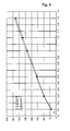
- Fig. 4 shows a damping force graph showing an actual damping force test result of the shock absorber in which the aforementioned valve mechanism is employed. It is noted from Fig, 4 that according to the shock absorber of the present invention, the damping force from the low speed range up to the high speed range is approximately linear.
- a structure of generating a two-step damping force is employed in a low speed rebound range of a piston, thereby making it possible to achieve an approximately linear damping force characteristic from a low speed range up to a high speed range. Accordingly, it is possible to considerably improve the ride comfort and handling stability of a vehicle.
- the present invention makes it possible to design a shock absorber capable of increasing a damping force in a low speed range without increasing a middle-high speed damping force.
- the advantage of a high degree of freedom of tuning a damping force can be further provided.
- the combination of a first valve disk and an auxiliary disk removes the necessity of a rebound retainer that has been required for keeping a compression channel in a conventional piston to be open, thereby enabling the piston and valve mechanism having a simple configuration to be embodied.
Landscapes
- Engineering & Computer Science (AREA)
- General Engineering & Computer Science (AREA)
- Civil Engineering (AREA)
- Structural Engineering (AREA)
- Mechanical Engineering (AREA)
- Fluid-Damping Devices (AREA)
Abstract
Description
- The present invention relates to a shock absorber, and more particularly, to a shock absorber for achieving generally linear damping force characteristics by improving a damping force characteristic in a low speed range of a piston.
- In general, a shock absorber is provided between a vehicle body and an axle to absorb a variety of vibrations or shocks transferred from a wheel in contact with a road in driving the vehicle, thereby improving the ride comfort and handling stability. In more detail, the shock absorber improves the ride comfort by absorbing free vibrations of its spring. Particularly, the shock absorber is configured to generate a damping force using a resistance against fluid flow during a rebound stroke of a piston installed in a cylinder of the shock absorber.
- Fig. 1 partially shows a conventional shock absorber. A
conventional shock absorber 100 includes a cylinder connected to an axle and having an outer cylinder (not shown) and aninner cylinder 110, and apiston rod 120 connected to a vehicle body. In addition, thepiston rod 120 extends into theinner cylinder 110 of the cylinder, and then an end of thepiston rod 120 is connected to apiston 130 in which compression andrebound channels inner cylinder 110 is divided into acompression chamber 112 and arebound chamber 114 by thepiston 130. Further, anintake valve disk 141 for opening thecompression channel 131 during a compression stroke is provided on top of thepiston 130, and avalve mechanism 160 for controlling the opening and closing and an opening degree of therebound channel 132 during a rebound stroke is provided on bottom of thepiston 130. - Particularly, the
valve mechanism 160 of the conventional shock absorber as described above controls the opening degree of therebound channel 132 in low and high speed ranges, thereby generating different damping forces. The concrete configuration of thevalve mechanism 160 is shown in an enlarged view of Fig. 1. As shown in the figure, theconventional valve mechanism 160 includes anut 172, awasher 174, a plurality ofvalve disks piston 130 by means of aretainer 176. Among them, thevalve disk 162 has aslit 162a, which is to detour fluid and generate a damping force, provided in a peripheral portion of theslit disk 162, thereby generating a low speed damping force in a low speed rebound range of thepiston 130. Thus, thevalve disk 162 is referred to as "slit disk" or "disk-S." In addition, a plurality of thevalve disks 164 are stacked on the bottom surface of theslit disk 162. Thevalve disks 164 are subjected to bending deformation by the fluid passing through theaforementioned slit 162a in a high speed rebound range of thepiston 130 and generate a high speed damping force. - However, in a process of generating the low speed damping force while the fluid passes through the
slit 162a of theslit disk 162, such a conventional shock absorber shows a nonlinear damping force characteristic, which is in proportion to the square of the speed of the piston. Such a nonlinear damping force characteristic causes a damping force characteristic in a low speed range to be degraded, which thus becomes the cause of deteriorating the ride comfort and handling stability of a vehicle. Further, the conventional shock absorber has the problem that a degree of freedom of tuning the damping force is also deteriorated since when the damping force in the low speed range is intended to be increased, a middle-high speed damping force is also increased. - Accordingly, the present invention is conceived to solve the aforementioned problems in the prior art. An object of the present invention is to provide a shock absorber capable of achieving an approximately linear damping force characteristic by employing a valve mechanism for generating a two-step damping force in a low speed rebound range of a piston and capable of increasing a degree of freedom of tuning a damping force.
- According to an aspect of the present invention for achieving the objects, there is provided a shock absorber having a piston formed with a rebound channel and a valve mechanism for generating a damping force by controlling opening and closing and an opening degree of the rebound channel. The valve mechanism according to the present invention comprises a first valve disk having a hole and a slit communicating with the rebound channel respectively provided in inner and outer sides of the first valve disk, the first valve disk generating a first damping force by detouring fluid through the slit; an auxiliary disk having a hole communicating with the hole of the first valve disk, the auxiliary disk being disposed to be in contact with a lower side of the first valve disk; and a second valve disk disposed to be in contact with a lower side of the auxiliary disk, the second valve disk being subjected to bending deformation by the fluid flowing through the holes of the first valve disk and the auxiliary disk to generate a second damping force. Therefore, the present invention can improve a damping force characteristic of a low speed rebound range by means of a structure of generating a two-step damping force by first and second valve disks in a low speed rebound range of the piston, which contribute to achieving a generally approximately linear damping force characteristic.
- In addition, the shock absorber according to the present invention may further comprise a third valve disk disposed to be spaced apart from the second valve disk, the third valve disk being subjected to bending deformation by the fluid passing the second valve disk to generate a third damping force. Preferably, there are a plurality of the auxiliary disks, the inner diameter of the holes of the auxiliary disks being gradually increased in a direction of fluid flow.
- The above and other objects, features and advantages of the present invention will become apparent from the following description of a preferred embodiment given in conjunction with the accompanying drawings, in which:
- Fig. 1 is a partial sectional view illustrating a conventional shock absorber;
- Fig. 2 is a partial sectional view illustrating a shock absorber according to an embodiment of the present invention;
- Fig. 3 is a view showing a valve mechanism for generating a damping force in the shock absorber shown in Fig. 2 together with a damping force graph anticipated from the valve mechanism; and
- Fig. 4 is a graph of a damping force showing an actual test result of the shock absorber manufactured according to the embodiment of the present invention.
- Hereinafter, a preferred embodiment of the present invention will be described in detail with reference to the accompanying drawings.
- Fig. 2 is a sectional view showing a portion of a shock absorber according to the embodiment of the present invention. As shown in the figure, a shock absorber 200 according to the present embodiment includes a
piston 230 dividing an interior of a cylinder, more particularly, aninner cylinder 210 into acompression chamber 212 and arebound chamber 214. The cylinder is connected to an axle, and thepiston 230 is connected to an end of apiston rod 220 connected to a vehicle body. In addition, thepiston 230 includescompression channels 231 far from the center of thepiston 230 andrebound channels 232 close thereto. The compression andrebound channels rebound chambers piston 230 rises and falls. - A
washer 241, anintake spring 242, aretainer 243 and an intake valve disk 244 are stacked on top of thepiston 230 in order from thereabove. The intake valve disk 244 is subjected to bending deformation with a fast response during the compression stroke of thepiston 230, thereby serving to open thecompression channels 231. In the meantime, arebound valve mechanism 260 which features in the present invention is provided in a lower portion of thepiston 230. As will be described in detail below, thevalve mechanism 260 is configured so as to generate an approximately linear damping force over low, middle-low and high speed rebound ranges of thepiston 230. - The
valve mechanism 260 according to the embodiment of the present invention includes first tothird valve disks piston rod 220 at a lower portion of thepiston 230 and fixed to thepiston rod 220 by means of anut 272 and awasher 274. In addition,auxiliary disks 264 are disposed between the first andsecond valve disks retainer 267 is disposed between the second andthird valve disks - The
first valve disk 262 is in contact with a lower surface of thepiston 230 and directly faces therebound channels 232. In addition, a peripheral portion of thefirst valve disk 262 is formed with a plurality ofslits 262a, which partially overlap with therebound channels 232 and detour the fluid flowing out of therebound channels 232. Also, thefirst valve disk 262 includesholes 262b, which generally communicate with theaforementioned rebound channels 232. - The plurality (three in the figure) of
auxiliary disks 264 are provided under thefirst valve disk 262. The uppermost one of theauxiliary disks 264 is in contact with a bottom surface of thefirst valve disk 262, and the other auxiliary disks are stacked on the uppermost auxiliary disk to be in contact with each other. Particularly, theauxiliary disks 264 are provided with a plurality ofholes 264b, which communicate with theholes 262b of thefirst valve disk 262 and are gradually increased in inner diameter as they go down. Theholes 264b allow the flow of the fluid passing throughrebound channels 232 and theholes 262b of thefirst valve disk 262. At this time, thefirst valve disk 262 and theauxiliary disks 264 keep a lower portion of thecompression channels 231 to be opened by the combination of the slits and holes, which removes the necessity of a rebound retainer that has been required in a piston of a conventional shock absorber. - The
second valve disks 266 are disposed under theauxiliary disks 264. Thesecond valve disks 266 are disposed so as to be in contact with the lowermost one of theauxiliary disks 264, and are formed to be subjected to bending deformation by the fluid passing through theholes 264b of theauxiliary disks 264. Thesecond valve disks 266 include a structure with two disks stacked in the present embodiment, but this is not limit the present invention. That is, the number, kind and/or thickness of the disks may be changed, thereby making it possible to design the valve mechanism for providing the manufacturer's desired damping force characteristic. - Finally, the
third valve disks 268 are provided under thesecond valve disks 266. Thethird valve disks 268 are fixed to thepiston rod 220 to be spaced apart by a predetermined gap from thesecond valve disks 266 by theretainer 267. In addition, thethird valve disks 268, which also have a structure with a plurality, preferably two, of disks stacked, are configured so as to be subjected to bending deformation by the fluid flowing while thesecond valve disks 266 are subjected to the bending deformation. At this time, the number, kind and/or thickness of the third valve disks are also considered when the valve mechanism is designed. - Fig. 3 is a view showing the aforementioned valve mechanism together with a graph of a damping force anticipated from the valve mechanism in order to describe the operation of the shock absorber according to the present embodiment.
- As shown in Figs. 2 and 3, in a low speed rebound range of the piston, the
first valve disk 262 first takes part in the generation of a damping force. That is, in the initial low speed rebound range, the fluid passes through theslits 262a of thefirst valve disk 262 and generates fluid resistance (or oil resistance), thereby generating and controlling an initial low speed damping force. Then, when the rebound speed of thepiston 230 is increased and therefore the pressure in therebound chamber 214 is also increased, the fluid passes through theholes 262b of thefirst valve disk 262 and theholes 264b of theauxiliary disks 264 sequentially. Thereafter, the fluid causes thesecond valve disks 266 to be subjected to the bending deformation. Accordingly, a primary blow off occurs at a point A in the damping force graph of Fig. 3. The primary blow off at the point A means that a two-step damping force is generated in the low speed rebound range, which contributes to achieving a gentle and approximately linear damping force graph. - Then, in the high speed rebound range in which the rebound speed of the piston is further increased and therefore the pressure in the
rebound chamber 214 is also further increased, the fluid, which causes thesecond valve disks 266 to be subjected to the bending deformation, causes thethird valve disks 268 to be subjected to the bending deformation and generates a high speed damping force. Accordingly, a secondary blow off occurs at a point B in the damping force graph of Fig. 3. The primary blow off is preceded in the low or middle-low speed rebound range before the secondary blow off occurs, thereby making it possible to achieve a gentle damping force graph in the high speed rebound range. - Therefore, the
first valve disk 262, theauxiliary disks 264, thesecond valve disks 266 and/or thethird valve disks 268 are employed in the shock absorber according to the present embodiment, thereby achieving an approximately linear, gentle damping force from the low speed rebound range up to the high speed rebound range. Particularly, the change of the damping force at the points A and B of the primary and secondary blow offs is gentle, which can considerably contribute to the improvement in the ride comfort and handling stability of a vehicle. Fig. 4 shows a damping force graph showing an actual damping force test result of the shock absorber in which the aforementioned valve mechanism is employed. It is noted from Fig, 4 that according to the shock absorber of the present invention, the damping force from the low speed range up to the high speed range is approximately linear. - In the present invention, a structure of generating a two-step damping force is employed in a low speed rebound range of a piston, thereby making it possible to achieve an approximately linear damping force characteristic from a low speed range up to a high speed range. Accordingly, it is possible to considerably improve the ride comfort and handling stability of a vehicle.
- Also, the present invention makes it possible to design a shock absorber capable of increasing a damping force in a low speed range without increasing a middle-high speed damping force. Thus, the advantage of a high degree of freedom of tuning a damping force can be further provided.
- Further, in the present invention, the combination of a first valve disk and an auxiliary disk removes the necessity of a rebound retainer that has been required for keeping a compression channel in a conventional piston to be open, thereby enabling the piston and valve mechanism having a simple configuration to be embodied.
- Although the present invention is described on the basis of the specified embodiment, those skilled in the art can make various modifications, changes and alterations thereto within the spirit and scope of the invention defined by the appended claims. Therefore, the aforementioned descriptions and drawings are not to limit the technical spirit of the present invention, but should be analyzed for illustrative purposes of the present invention.
Claims (4)
- A shock absorber having a piston formed with a rebound channel and a valve mechanism for generating a damping force by controlling opening and closing and an opening degree of the rebound channel,
wherein the valve mechanism comprises:a first valve disk having a hole and a slit communicating with the rebound channel respectively provided in inner and outer sides of the first valve disk, the first valve disk generating a first damping force by detouring fluid through the slit;an auxiliary disk having a hole communicating with the hole of the first valve disk, the auxiliary disk being disposed to be in contact with a lower side of the first valve disk; anda second valve disk disposed to be in contact with a lower side of the auxiliary disk, the second valve disk being subjected to bending deformation by the fluid flowing through the holes of the first valve disk and the auxiliary disk to generate a second damping force. - A shock absorber having a piston formed with a rebound channel and a valve mechanism for generating a damping force by controlling opening and closing and an opening degree of the rebound channel,
wherein the valve mechanism comprises:a first valve disk having a portion in an outer side thereof for generating a first damping force by detouring at least a portion of fluid passing through the rebound channel, and a separate hole communicating with the rebound channel in an inner side of the first valve disk;an auxiliary disk having a hole communicating with the hole of the first valve disk, the auxiliary disk being disposed to be in contact with a lower side of the first valve disk; anda second valve disk disposed to be in contact with a lower side of the auxiliary disk, the second valve disk generating a second damping force by the fluid flowing through the holes of the first valve disk and the auxiliary disk. - The shock absorber as claimed in claim 1 or 2, further comprising a third valve disk disposed to be spaced apart from the second valve disk, the third valve disk being subjected to bending deformation by the fluid passing the second valve disk to generate a third damping force.
- The shock absorber as claimed in claim 1 or 2, wherein there are a plurality of the auxiliary disks, the inner diameter of the holes of the auxiliary disks being gradually increased in a direction of fluid flow.
Applications Claiming Priority (1)
| Application Number | Priority Date | Filing Date | Title |
|---|---|---|---|
| KR1020060006809A KR100773363B1 (en) | 2006-01-23 | 2006-01-23 | Shock absorber for implementing linear damping force characteristics |
Publications (2)
| Publication Number | Publication Date |
|---|---|
| EP1811196A1 true EP1811196A1 (en) | 2007-07-25 |
| EP1811196B1 EP1811196B1 (en) | 2009-09-02 |
Family
ID=37950204
Family Applications (1)
| Application Number | Title | Priority Date | Filing Date |
|---|---|---|---|
| EP07000335A Active EP1811196B1 (en) | 2006-01-23 | 2007-01-09 | Shock absorber for achieving linear damping force characteristics |
Country Status (7)
| Country | Link |
|---|---|
| US (1) | US7789208B2 (en) |
| EP (1) | EP1811196B1 (en) |
| JP (1) | JP2007198592A (en) |
| KR (1) | KR100773363B1 (en) |
| CN (1) | CN101008429A (en) |
| DE (1) | DE602007002204D1 (en) |
| TR (1) | TR200607525A2 (en) |
Cited By (1)
| Publication number | Priority date | Publication date | Assignee | Title |
|---|---|---|---|---|
| CN105370783A (en) * | 2015-12-01 | 2016-03-02 | 唐山轨道客车有限责任公司 | Snaking-resistive shock absorber, non-power bogie and rail vehicle |
Families Citing this family (17)
| Publication number | Priority date | Publication date | Assignee | Title |
|---|---|---|---|---|
| KR100880165B1 (en) * | 2007-09-05 | 2009-01-23 | 주식회사 만도 | Shock absorber valve device |
| KR100884621B1 (en) * | 2007-12-05 | 2009-02-23 | 주식회사 만도 | Shock absorber valve device |
| US8297418B2 (en) | 2008-06-05 | 2012-10-30 | Tenneco Automotive Operating Company Inc. | Nested check high speed valve |
| JP5427016B2 (en) * | 2008-12-24 | 2014-02-26 | カヤバ工業株式会社 | Damping valve |
| JP5192441B2 (en) * | 2009-05-20 | 2013-05-08 | カヤバ工業株式会社 | Damping valve |
| CN102072274A (en) * | 2011-01-27 | 2011-05-25 | 浙江路得坦摩汽车悬架系统有限公司 | Piston valve structure for damper |
| JP5812650B2 (en) * | 2011-03-31 | 2015-11-17 | 日立オートモティブシステムズ株式会社 | Damping force adjustable shock absorber |
| JP5785510B2 (en) * | 2012-03-14 | 2015-09-30 | カヤバ工業株式会社 | Buffer valve structure |
| JP5613191B2 (en) * | 2012-03-28 | 2014-10-22 | カヤバ工業株式会社 | Valve structure |
| KR101374877B1 (en) * | 2012-06-13 | 2014-03-18 | 주식회사 만도 | Piston assembly of shock absorber |
| JP5715598B2 (en) * | 2012-06-27 | 2015-05-07 | カヤバ工業株式会社 | Damping valve |
| JP2014194259A (en) * | 2013-03-29 | 2014-10-09 | Hitachi Automotive Systems Ltd | Buffer |
| US9441699B2 (en) * | 2013-05-13 | 2016-09-13 | Tenneco Automotive Operating Company Inc. | Orifice disc for regulating flow in damper |
| WO2015023845A1 (en) * | 2013-08-14 | 2015-02-19 | Tenneco Automotive Operating Company Inc. | Low pressure high compression damping monotube shock absorber |
| DE102016213328B4 (en) * | 2016-07-21 | 2020-06-18 | Zf Friedrichshafen Ag | Damping valve with direction-dependent pre-opening cross-section for a vibration damper |
| US10239376B2 (en) | 2016-09-22 | 2019-03-26 | Beijingwest Industries Co., Ltd. | Hydraulic damper with an x-flow piston assembly |
| KR20180083721A (en) * | 2017-01-13 | 2018-07-23 | 주식회사 만도 | Valve structure of a shock absorber |
Citations (4)
| Publication number | Priority date | Publication date | Assignee | Title |
|---|---|---|---|---|
| DE3932669A1 (en) * | 1988-09-29 | 1990-04-12 | Atsugi Unisia Corp | HYDRAULIC SHOCK ABSORBER WITH LINEAR DAMPING CHARACTERISTICS |
| WO1992016769A1 (en) * | 1991-03-14 | 1992-10-01 | Monroe Auto Equipment Company | Tunable hydraulic valve for shock absorber |
| JPH11101292A (en) * | 1997-09-30 | 1999-04-13 | Tokico Ltd | Damping force adjustable hydraulic shock absorber |
| JP2003042214A (en) * | 2001-07-31 | 2003-02-13 | Kayaba Ind Co Ltd | Hydraulic shock absorber |
Family Cites Families (13)
| Publication number | Priority date | Publication date | Assignee | Title |
|---|---|---|---|---|
| US5316113A (en) * | 1987-11-19 | 1994-05-31 | Atsugi Motor Parts Company Ltd. | Hydraulic shock absorber |
| US4964493A (en) * | 1988-04-06 | 1990-10-23 | Atsugi Motor Parts Company, Limited | Shock absorber with variable damping characteristics depending upon stroke speed |
| DE3840302C2 (en) * | 1988-11-30 | 1999-06-10 | Mannesmann Sachs Ag | Low-noise damping valve |
| JPH07238979A (en) * | 1994-02-25 | 1995-09-12 | Unisia Jecs Corp | Variable damping force type hydraulic shock absorber |
| KR0150383B1 (en) | 1995-12-15 | 1998-09-15 | 정몽원 | Piston valve for a shock-absorber |
| JP2002295566A (en) | 2001-03-29 | 2002-10-09 | Tokico Ltd | Damping force adjustable hydraulic shock absorber |
| JP2003014028A (en) * | 2001-06-28 | 2003-01-15 | Tokico Ltd | Hydraulic shock absorber |
| JP4055060B2 (en) | 2002-09-30 | 2008-03-05 | 株式会社日立製作所 | Hydraulic shock absorber |
| JP4552177B2 (en) | 2003-03-31 | 2010-09-29 | 日立オートモティブシステムズ株式会社 | Damping force adjustable shock absorber |
| US7097016B2 (en) * | 2003-09-05 | 2006-08-29 | Tenneco Automotive Operating Company Inc. | Fulcrum blow off valve for use in a shock absorber |
| JP2005127374A (en) | 2003-10-22 | 2005-05-19 | Hitachi Ltd | Hydraulic buffer |
| JP2005201398A (en) * | 2004-01-16 | 2005-07-28 | Showa Corp | Hydraulic shock absorber valve structure |
| JP4318080B2 (en) | 2004-06-07 | 2009-08-19 | 株式会社日立製作所 | Hydraulic shock absorber |
-
2006
- 2006-01-23 KR KR1020060006809A patent/KR100773363B1/en not_active Expired - Fee Related
- 2006-12-27 TR TR2006/07525A patent/TR200607525A2/en unknown
- 2006-12-28 JP JP2006354733A patent/JP2007198592A/en active Pending
-
2007
- 2007-01-09 US US11/621,481 patent/US7789208B2/en active Active
- 2007-01-09 EP EP07000335A patent/EP1811196B1/en active Active
- 2007-01-09 CN CNA2007100016315A patent/CN101008429A/en active Pending
- 2007-01-09 DE DE602007002204T patent/DE602007002204D1/en active Active
Patent Citations (4)
| Publication number | Priority date | Publication date | Assignee | Title |
|---|---|---|---|---|
| DE3932669A1 (en) * | 1988-09-29 | 1990-04-12 | Atsugi Unisia Corp | HYDRAULIC SHOCK ABSORBER WITH LINEAR DAMPING CHARACTERISTICS |
| WO1992016769A1 (en) * | 1991-03-14 | 1992-10-01 | Monroe Auto Equipment Company | Tunable hydraulic valve for shock absorber |
| JPH11101292A (en) * | 1997-09-30 | 1999-04-13 | Tokico Ltd | Damping force adjustable hydraulic shock absorber |
| JP2003042214A (en) * | 2001-07-31 | 2003-02-13 | Kayaba Ind Co Ltd | Hydraulic shock absorber |
Cited By (2)
| Publication number | Priority date | Publication date | Assignee | Title |
|---|---|---|---|---|
| CN105370783A (en) * | 2015-12-01 | 2016-03-02 | 唐山轨道客车有限责任公司 | Snaking-resistive shock absorber, non-power bogie and rail vehicle |
| CN105370783B (en) * | 2015-12-01 | 2018-06-26 | 中车唐山机车车辆有限公司 | Resist snakelike damper, non-powered bogie and rail vehicle |
Also Published As
| Publication number | Publication date |
|---|---|
| TR200607525A2 (en) | 2007-10-22 |
| KR20070077315A (en) | 2007-07-26 |
| DE602007002204D1 (en) | 2009-10-15 |
| JP2007198592A (en) | 2007-08-09 |
| US7789208B2 (en) | 2010-09-07 |
| KR100773363B1 (en) | 2007-11-05 |
| CN101008429A (en) | 2007-08-01 |
| US20070170028A1 (en) | 2007-07-26 |
| EP1811196B1 (en) | 2009-09-02 |
Similar Documents
| Publication | Publication Date | Title |
|---|---|---|
| EP1811196B1 (en) | Shock absorber for achieving linear damping force characteristics | |
| US9797466B2 (en) | Damping force variable type shock absorber | |
| US9067471B2 (en) | Piston assembly with open bleed | |
| US7431135B2 (en) | Stroke dependent damping | |
| US9587703B2 (en) | Variable radius spring disc for vehicle shock absorber | |
| JP2008241017A (en) | Hydraulic shock absorber | |
| US20090236194A1 (en) | Valve apparatus of shock absorber | |
| US20100326781A1 (en) | Piston valve assembly of shock absorber | |
| CN104603495A (en) | Multi-tuneable degressive valve | |
| JP2010169256A (en) | Damping valve | |
| US12540653B2 (en) | Shock absorber | |
| JP2008274991A (en) | Piston valve device of hydraulic shock absorber | |
| JP2000055103A (en) | Hydraulic shock absorber | |
| JP4663379B2 (en) | Hydraulic shock absorber for vehicles | |
| KR100880165B1 (en) | Shock absorber valve device | |
| JP5905805B2 (en) | Hydraulic shock absorber and valve | |
| US20030192756A1 (en) | Rotary cam backup washer for disc valve adjustment | |
| JP2005201398A (en) | Hydraulic shock absorber valve structure | |
| JP2009030789A (en) | Valve structure of pneumatic shock absorber | |
| EP4682398A1 (en) | Spring with tapered arms for shock absorber | |
| KR100884621B1 (en) | Shock absorber valve device | |
| KR20090100545A (en) | Shock absorber | |
| JP2010164121A (en) | Valve structure | |
| EP1484527A1 (en) | Shock absorber with rotary cam backup washer for disc valve adjustment | |
| JP2006283923A (en) | Hydraulic damper for vehicle |
Legal Events
| Date | Code | Title | Description |
|---|---|---|---|
| PUAI | Public reference made under article 153(3) epc to a published international application that has entered the european phase |
Free format text: ORIGINAL CODE: 0009012 |
|
| AK | Designated contracting states |
Kind code of ref document: A1 Designated state(s): AT BE BG CH CY CZ DE DK EE ES FI FR GB GR HU IE IS IT LI LT LU LV MC NL PL PT RO SE SI SK TR |
|
| AX | Request for extension of the european patent |
Extension state: AL BA HR MK YU |
|
| 17P | Request for examination filed |
Effective date: 20070806 |
|
| 17Q | First examination report despatched |
Effective date: 20070907 |
|
| AKX | Designation fees paid |
Designated state(s): DE FR GB IT |
|
| GRAP | Despatch of communication of intention to grant a patent |
Free format text: ORIGINAL CODE: EPIDOSNIGR1 |
|
| GRAS | Grant fee paid |
Free format text: ORIGINAL CODE: EPIDOSNIGR3 |
|
| GRAA | (expected) grant |
Free format text: ORIGINAL CODE: 0009210 |
|
| AK | Designated contracting states |
Kind code of ref document: B1 Designated state(s): DE FR GB IT |
|
| REF | Corresponds to: |
Ref document number: 602007002204 Country of ref document: DE Date of ref document: 20091015 Kind code of ref document: P |
|
| PLBE | No opposition filed within time limit |
Free format text: ORIGINAL CODE: 0009261 |
|
| STAA | Information on the status of an ep patent application or granted ep patent |
Free format text: STATUS: NO OPPOSITION FILED WITHIN TIME LIMIT |
|
| 26N | No opposition filed |
Effective date: 20100603 |
|
| REG | Reference to a national code |
Ref country code: FR Ref legal event code: ST Effective date: 20100930 |
|
| PG25 | Lapsed in a contracting state [announced via postgrant information from national office to epo] |
Ref country code: FR Free format text: LAPSE BECAUSE OF NON-PAYMENT OF DUE FEES Effective date: 20100201 |
|
| PG25 | Lapsed in a contracting state [announced via postgrant information from national office to epo] |
Ref country code: IT Free format text: LAPSE BECAUSE OF FAILURE TO SUBMIT A TRANSLATION OF THE DESCRIPTION OR TO PAY THE FEE WITHIN THE PRESCRIBED TIME-LIMIT Effective date: 20090902 |
|
| GBPC | Gb: european patent ceased through non-payment of renewal fee |
Effective date: 20110109 |
|
| PG25 | Lapsed in a contracting state [announced via postgrant information from national office to epo] |
Ref country code: GB Free format text: LAPSE BECAUSE OF NON-PAYMENT OF DUE FEES Effective date: 20110109 |
|
| REG | Reference to a national code |
Ref country code: DE Ref legal event code: R082 Ref document number: 602007002204 Country of ref document: DE Representative=s name: CBDL PATENTANWAELTE GBR, DE Ref country code: DE Ref legal event code: R082 Ref document number: 602007002204 Country of ref document: DE Representative=s name: CBDL PATENTANWAELTE EGBR, DE |
|
| PGFP | Annual fee paid to national office [announced via postgrant information from national office to epo] |
Ref country code: DE Payment date: 20251120 Year of fee payment: 20 |