EP1811084A2 - Procédé et dispositif de dégazage d'une composition fluide ou pâteuse - Google Patents
Procédé et dispositif de dégazage d'une composition fluide ou pâteuse Download PDFInfo
- Publication number
- EP1811084A2 EP1811084A2 EP06122731A EP06122731A EP1811084A2 EP 1811084 A2 EP1811084 A2 EP 1811084A2 EP 06122731 A EP06122731 A EP 06122731A EP 06122731 A EP06122731 A EP 06122731A EP 1811084 A2 EP1811084 A2 EP 1811084A2
- Authority
- EP
- European Patent Office
- Prior art keywords
- degassed
- medium
- gas
- degassing
- cyclone
- Prior art date
- Legal status (The legal status is an assumption and is not a legal conclusion. Google has not performed a legal analysis and makes no representation as to the accuracy of the status listed.)
- Withdrawn
Links
Images
Classifications
-
- D—TEXTILES; PAPER
- D21—PAPER-MAKING; PRODUCTION OF CELLULOSE
- D21H—PULP COMPOSITIONS; PREPARATION THEREOF NOT COVERED BY SUBCLASSES D21C OR D21D; IMPREGNATING OR COATING OF PAPER; TREATMENT OF FINISHED PAPER NOT COVERED BY CLASS B31 OR SUBCLASS D21G; PAPER NOT OTHERWISE PROVIDED FOR
- D21H23/00—Processes or apparatus for adding material to the pulp or to the paper
- D21H23/78—Controlling or regulating not limited to any particular process or apparatus
-
- B—PERFORMING OPERATIONS; TRANSPORTING
- B01—PHYSICAL OR CHEMICAL PROCESSES OR APPARATUS IN GENERAL
- B01D—SEPARATION
- B01D19/00—Degasification of liquids
- B01D19/0036—Flash degasification
-
- B—PERFORMING OPERATIONS; TRANSPORTING
- B01—PHYSICAL OR CHEMICAL PROCESSES OR APPARATUS IN GENERAL
- B01D—SEPARATION
- B01D19/00—Degasification of liquids
- B01D19/0042—Degasification of liquids modifying the liquid flow
- B01D19/0052—Degasification of liquids modifying the liquid flow in rotating vessels, vessels containing movable parts or in which centrifugal movement is caused
- B01D19/0057—Degasification of liquids modifying the liquid flow in rotating vessels, vessels containing movable parts or in which centrifugal movement is caused the centrifugal movement being caused by a vortex, e.g. using a cyclone, or by a tangential inlet
-
- D—TEXTILES; PAPER
- D21—PAPER-MAKING; PRODUCTION OF CELLULOSE
- D21H—PULP COMPOSITIONS; PREPARATION THEREOF NOT COVERED BY SUBCLASSES D21C OR D21D; IMPREGNATING OR COATING OF PAPER; TREATMENT OF FINISHED PAPER NOT COVERED BY CLASS B31 OR SUBCLASS D21G; PAPER NOT OTHERWISE PROVIDED FOR
- D21H23/00—Processes or apparatus for adding material to the pulp or to the paper
- D21H23/02—Processes or apparatus for adding material to the pulp or to the paper characterised by the manner in which substances are added
- D21H23/22—Addition to the formed paper
- D21H23/46—Pouring or allowing the fluid to flow in a continuous stream on to the surface, the entire stream being carried away by the paper
- D21H23/48—Curtain coaters
Definitions
- the invention relates to a method and a device, in particular a coating color for coating paper or cardboard, wherein the medium to be degassed is introduced into a vacuum vessel and thereby largely degassed, wherein gas and the largely degassed medium are discharged separately.
- the medium is, in particular, a coating color with which, in particular, a paper, cardboard or other fibrous web is to be removed during its production or finishing process for the purpose of improving its printability and optical properties.
- the coating color generally consists of aqueous pigment dispersion which is applied as uniformly as possible with a certain film thickness and then dried.
- free-jet nozzle applicators mechanical deaerators that operate on an eddy-current or cyclone principle are often used.
- This gas bubbles can be removed with a size of 200 microns. Smaller gas bubbles stay in the coating color or are still reduced by the relatively high shear forces in the cyclone, so they are no longer disturbing in the free jet.
- the efficiency of the cyclone gasifier is about 40 to 70%, so that even after passing through the degasser gas or air is included in the coating color. Since very large gas bubbles are removed one hundred percent and only these large bubbles interfere with the free jet application, the efficiency is sufficient for this type of coating.
- Zyklonentgaser are also known from the patent funds and indeed for example from the EP-A1 0618012 and the US 5,080,792 .
- the medium to be degassed is introduced eccentrically into a stationary container, so that adjusts a swirling motion of the medium in the interior of the container.
- the centrifugal force caused by this swirling movement by utilizing the density differences between the medium to be degassed on the one hand and the gas enclosed therein on the other hand, ensures separation of medium and gas.
- fibrous webs are to be coated by means of the curtain coating method.
- the application medium in the amount in which it should also remain on the fibrous web, in free fall, that is applied in the form of a free-falling and closed curtain on the fibrous web.
- the requirements for this are Application medium (coating color) extremely high, which is why a particularly largely degassed medium is necessary.
- the functional principle of this degasser is based on the production of thin layers of medium to be degassed, which run through the vacuum degasser as long as possible.
- the absolute pressure in the vacuum degasser is between 10 and 300 mbar, in particular between 30 and 100 mbar. It has been found that the efficiency of this proposed vacuum degasser is much better than that of the known cyclone gasifier. The efficiency is about 95 to 99%.
- the Applicant is known a device in which a degassing at least one further downstream, wherein all successively and / or mutually parallel degassing are vacuum degasser.
- the degree of separation of the one vacuum degasser or the plurality of vacuum degassers is not sufficient to ensure optimum degassing or venting.
- the invention is therefore based on the object to provide a method and an apparatus with which an even better degassing is possible.
- the object is achieved according to the invention with a method according to claim 1 in such a way that before degassing in the known vacuum container, the medium to be degassed additionally at least one degassing is subjected in a known cyclone gasifier, wherein a resulting gas-containing volume flow or foam and a volume of degassed medium are also removed separately.
- This vorentgaste by eddy current or Zyklonentgasung medium is now fed to a vacuum degasser.
- the inventors have recognized that the gas content in the coating color can be reduced by a combination of cyclone gassing or cyclone deaeration and vacuum degassing or vacuum deaeration so that in the end no visible disturbances caused by a gas content are present on the surface of the web.
- this differential pressure should be between 1 and 4 bar, preferably between 1.5 and 2.5 bar.
- the gas bubbles separated in the cyclone gasification are removed via a foam line to the outside.
- the volume flow at this gas-containing fraction is less than 15% of the total volume flow, in particular in the range between 1 and 10%. This separated volume flow can be discarded, as well as in one Working and collecting container are returned to it then again in the cycle to subject said degassing.
- curtain coating is a very gentle and application medium-saving application method, since no device parts of the coater touch the web and only so much application medium is to be applied, as should remain on the web or substrate.
- the object of the invention is also achieved with a device for carrying out the method.
- the per se known vacuum container is preceded by a cyclone gas known per se.
- the cyclone gasifier has an inlet for the medium to be degassed, a discharge line for a resulting gas-containing volume flow, and an outlet and a discharge line for the pre-degassed medium.
- Another very advantageous embodiment of the device may consist in that the cyclone gasifier has at least one unit through which the gas to be degassed flows.
- these units are advantageously designed for different flow volumes, for example 10 l / min, 5 l / min and 2.5 l / min.
- the plurality of units each have the same size flow volume.
- four units can be flowed through in parallel.
- the individual units can be switched on and off by valves. This achieves a high flexibility in the flow and can still achieve a differential pressure between the inlet and outlet of the cyclone gasifier.
- differential pressure between the inlet and the outlet of the cyclone gasifier are provided between 1 and 4 bar, preferably between 1.5 to 2.5 bar.
- a further advantageous solution may be to install a plurality of cyclone gas generators in series in front of the vacuum degasser. As a result, the degassing effect is further improved.
- the advantage of the invention consists in a very extensive ventilation of the existing medium. In the case of coating colors, there are no visible disturbances on the surface of the web, which results in a higher quality of application than hitherto.
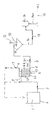
- FIG. 1 shows how a liquid to pasty medium 1, i. a coating or spreading medium in the form of a high-viscosity coating color for finishing a running paper or board web is degassed before coating.
- the device shown has a working container 2 in which the medium 1 to be degassed is stored.
- the medium 1 is first fed via a line 3 in the direction of the arrow to a first degasser, namely a cyclone gasifier 4.
- the supply takes place tangentially, as a result of which the specifically lighter gas or the air contained can collect in the center of the vortex caused by an eddy current and can be easily dissipated.
- the cyclone gasifier 4 thus has a tangential inlet 5 for the medium 1 to be degassed, a discharge line 6 for a gas-containing volumetric flow or foam 7, and an outlet 8 and a discharge line 9 for the pre-degassed medium 1a.
- this degasser 4 may be divided into individual units. At least one unit is provided, in the example, however, four pieces. The individual units are flowed through in parallel by the medium to be degassed and are with 4.1; 4.2; 4.3 and 4.4. Individual units or individual cyclones 4.1 to 4.4 (or even 4.n for even more cyclone units) can then be switched on or off depending on the current flow.
- This configuration achieves more flexibility in the flow and yet can achieve a necessary differential pressure of about 2bar.
- the desired flow volumes can be set in each unit.
- In the first unit 4.1 are in the example 10 I / min, in the second unit 4.3 are 5 I / min and in the other units 4.3 and 4.4 each 2.5 I / min by not marked with valves and can be switched off.
- this embodiment allows the pressure difference to be set for a wide range of viscosities.
- the pre-degassed medium 1a is fed to a downstream vacuum degasser 10 from the bottom of the cyclone gasifier 4 via a discharge line 9.
- An inlet 11 for the medium to be de-gassed 1a and also a vacuum connection or vacuum generator 12 are provided on the lid of the vacuum degasser 10.
- the vacuum degasser 10 may have various shapes and internal configurations for the purpose of achieving a prolonged flow path and achieving a thin film to be degassed without increasing the container geometry. Installations are possible in the form of a centrally arranged, vertical drive shaft with at least one coaxially arranged turntable with rotational speeds of about 2500 1 / min, or the arrangement of Hochrotationszerstäuberdüsen with speeds up to 20000 1 / min for supplying the Medium, the installation of chutes in cascade form and the like, which will not be discussed here in detail.
- the absolute pressure in the vacuum degasser 10 is set to about 100 to 300 mbar, preferably 1-100 mbar. At a temperature of 30 to 50 ° C of the medium 1 is then the remaining degassing, wherein a virtually gas-free medium 1b. receives.
- This degassed medium 1b is fed via a discharge line 13 in the direction of the arrow of a vacuum device 10 directly downstream of the coating device, in particular a curtain applicator 14.
- the term "practically gas-free" means that realistically no 100% degassing is possible.
- pumps, filters and also pulsation dampers are incorporated in the process sequence or the device provided for this purpose, which are not shown here separately because of their prominence. Likewise, the drawing of the individual inlet and shut-off valves was omitted.
Landscapes
- Chemical & Material Sciences (AREA)
- Chemical Kinetics & Catalysis (AREA)
- Paper (AREA)
- Application Of Or Painting With Fluid Materials (AREA)
- Degasification And Air Bubble Elimination (AREA)
Applications Claiming Priority (1)
| Application Number | Priority Date | Filing Date | Title |
|---|---|---|---|
| DE200510060848 DE102005060848A1 (de) | 2005-12-16 | 2005-12-16 | Verfahren und Vorrichtung zum Entgasen eines flüssigen bis pastösen Mediums |
Publications (2)
| Publication Number | Publication Date |
|---|---|
| EP1811084A2 true EP1811084A2 (fr) | 2007-07-25 |
| EP1811084A3 EP1811084A3 (fr) | 2011-07-13 |
Family
ID=38098612
Family Applications (1)
| Application Number | Title | Priority Date | Filing Date |
|---|---|---|---|
| EP06122731A Withdrawn EP1811084A3 (fr) | 2005-12-16 | 2006-10-23 | Procédé et dispositif de dégazage d'une composition fluide ou pâteuse |
Country Status (2)
| Country | Link |
|---|---|
| EP (1) | EP1811084A3 (fr) |
| DE (1) | DE102005060848A1 (fr) |
Cited By (3)
| Publication number | Priority date | Publication date | Assignee | Title |
|---|---|---|---|---|
| CN103882775A (zh) * | 2012-12-24 | 2014-06-25 | 中国制浆造纸研究院 | 一种用于涂料除气的方法 |
| WO2016138599A1 (fr) * | 2015-03-03 | 2016-09-09 | Imi Hydronic Engineering Switzerland Ag | Dispositif pour un dégazage d'un liquide |
| WO2021239310A1 (fr) * | 2020-05-27 | 2021-12-02 | Voith Patent Gmbh | Dispositif de revêtement |
Families Citing this family (2)
| Publication number | Priority date | Publication date | Assignee | Title |
|---|---|---|---|---|
| DE102008000451A1 (de) | 2008-02-29 | 2009-09-03 | Voith Patent Gmbh | Streichstation |
| DE102011002671A1 (de) | 2011-01-13 | 2012-07-19 | Metso Paper, Inc. | Leimmittelzuführsystem zum Zuführen von Leimmittel zu einer Papier- oder Kartonbahn |
Family Cites Families (3)
| Publication number | Priority date | Publication date | Assignee | Title |
|---|---|---|---|---|
| US5149341A (en) * | 1991-08-23 | 1992-09-22 | Taylor John A | Paper coater skip prevention and deaeration apparatus and method |
| ATE368149T1 (de) * | 2001-02-16 | 2007-08-15 | Voith Patent Gmbh | Verfahren zur herstellung von gestrichenem papier oder karton& x9; |
| DE10352807A1 (de) * | 2003-11-12 | 2005-06-23 | Voith Paper Patent Gmbh | Auftragsvorrichtung |
-
2005
- 2005-12-16 DE DE200510060848 patent/DE102005060848A1/de not_active Withdrawn
-
2006
- 2006-10-23 EP EP06122731A patent/EP1811084A3/fr not_active Withdrawn
Cited By (3)
| Publication number | Priority date | Publication date | Assignee | Title |
|---|---|---|---|---|
| CN103882775A (zh) * | 2012-12-24 | 2014-06-25 | 中国制浆造纸研究院 | 一种用于涂料除气的方法 |
| WO2016138599A1 (fr) * | 2015-03-03 | 2016-09-09 | Imi Hydronic Engineering Switzerland Ag | Dispositif pour un dégazage d'un liquide |
| WO2021239310A1 (fr) * | 2020-05-27 | 2021-12-02 | Voith Patent Gmbh | Dispositif de revêtement |
Also Published As
| Publication number | Publication date |
|---|---|
| EP1811084A3 (fr) | 2011-07-13 |
| DE102005060848A1 (de) | 2007-06-28 |
Similar Documents
| Publication | Publication Date | Title |
|---|---|---|
| DE69213828T2 (de) | Verfahren zur Herstellung von Streichdruckpapier | |
| EP0501144B1 (fr) | Dispositif pour le désaérage d'une suspension de pâte à papier et son utilisation | |
| DE60225332T2 (de) | Verfahren und vorrichtung zum vorhanggiessen | |
| DE102014100605A1 (de) | Düsenanordnung mit selbstreinigender Frontfläche | |
| DE69601080T2 (de) | Düse mit begrenztem Durchfluss | |
| DE69723362T2 (de) | Homogenisierventil | |
| DE69218615T2 (de) | Ein papierbeschichtungssystem und verfahren | |
| EP1811084A2 (fr) | Procédé et dispositif de dégazage d'une composition fluide ou pâteuse | |
| CH626817A5 (fr) | ||
| DE19615089C1 (de) | Flotationsverfahren und Vorrichtung zu seiner Durchführung | |
| WO2008028722A1 (fr) | Dispositif de dÉgazage | |
| DE102005060846A1 (de) | Verfahren und Vorrichtung zum Entgasen eines flüssigen bis pastösen Mediums, insbesondere einer Streichfarbe | |
| EP1798333B1 (fr) | Appareil pour dégazer une substance liquide ou pâteuse, en particulier une couleur d'enduction | |
| DE4125513A1 (de) | Verfahren zum vermischen von suspendiertem faserstoff sowie vorrichtungen zu dessen ausfuehrung | |
| EP1798332A1 (fr) | Procédé et dispositif de dégazage den matériau fluide ou pâteux | |
| EP4380711A1 (fr) | Dispositif et procédé pour séparer des mélanges de fluides | |
| DE102005060850A1 (de) | Vorrichtung und Verfahren zum Entgasen eines flüssigen bis pastösen Mediums, insbesondere einer Streichfarbe | |
| DE19923600A1 (de) | Verfahren zur Aufbereitung von mineralischen Rohstoffen, insbesondere von Steinkohle | |
| DE102005060849A1 (de) | Vorrichtung und Verfahren zum Entgasen eines flüssigen bis pastösen Mediums, insbesondere einer Streichfarbe | |
| CH655748A5 (de) | Verfahren zur ausscheidung von klebrigen verunreinigungen aus stoffsuspension sowie vorrichtung zur ausfuehrung des verfahrens. | |
| EP0641587B1 (fr) | Procédé pour séparer des dispersions de particules dans un liquide dans des portions riches et pauvres en particules | |
| EP1559833A1 (fr) | Preparation continue controlée de sauces de couchage | |
| DE69508455T2 (de) | Luft/Gas-Abtrennvorrichtung | |
| DE102022208536B3 (de) | Verfahren zur Entfernung von Gasblasen aus einer Hydraulikflüssigkeit und Hydraulikanlage mit Gasblasenentfernungseinrichtung | |
| DE102007000722A1 (de) | Verfahren und Vorrichtung zum Entgasen von flüssigen bis pastösen Medien, insbesondere Streichfarben |
Legal Events
| Date | Code | Title | Description |
|---|---|---|---|
| PUAI | Public reference made under article 153(3) epc to a published international application that has entered the european phase |
Free format text: ORIGINAL CODE: 0009012 |
|
| AK | Designated contracting states |
Kind code of ref document: A2 Designated state(s): AT BE BG CH CY CZ DE DK EE ES FI FR GB GR HU IE IS IT LI LT LU LV MC NL PL PT RO SE SI SK TR |
|
| AX | Request for extension of the european patent |
Extension state: AL BA HR MK YU |
|
| PUAL | Search report despatched |
Free format text: ORIGINAL CODE: 0009013 |
|
| AK | Designated contracting states |
Kind code of ref document: A3 Designated state(s): AT BE BG CH CY CZ DE DK EE ES FI FR GB GR HU IE IS IT LI LT LU LV MC NL PL PT RO SE SI SK TR |
|
| AX | Request for extension of the european patent |
Extension state: AL BA HR MK RS |
|
| RIC1 | Information provided on ipc code assigned before grant |
Ipc: B01D 19/00 20060101ALI20110606BHEP Ipc: D21H 23/22 20060101AFI20070611BHEP |
|
| 17P | Request for examination filed |
Effective date: 20120113 |
|
| AKX | Designation fees paid |
Designated state(s): AT BE BG CH CY CZ DE DK EE ES FI FR GB GR HU IE IS IT LI LT LU LV MC NL PL PT RO SE SI SK TR |
|
| STAA | Information on the status of an ep patent application or granted ep patent |
Free format text: STATUS: THE APPLICATION IS DEEMED TO BE WITHDRAWN |
|
| 18D | Application deemed to be withdrawn |
Effective date: 20120114 |