EP1808601A2 - Regelventil für einen Verdichter variabler Verdrängung - Google Patents
Regelventil für einen Verdichter variabler Verdrängung Download PDFInfo
- Publication number
- EP1808601A2 EP1808601A2 EP07000519A EP07000519A EP1808601A2 EP 1808601 A2 EP1808601 A2 EP 1808601A2 EP 07000519 A EP07000519 A EP 07000519A EP 07000519 A EP07000519 A EP 07000519A EP 1808601 A2 EP1808601 A2 EP 1808601A2
- Authority
- EP
- European Patent Office
- Prior art keywords
- control valve
- valve
- pressure
- port
- valve element
- Prior art date
- Legal status (The legal status is an assumption and is not a legal conclusion. Google has not performed a legal analysis and makes no representation as to the accuracy of the status listed.)
- Withdrawn
Links
- 238000006073 displacement reaction Methods 0.000 title claims abstract description 36
- 239000003507 refrigerant Substances 0.000 claims description 72
- 238000011144 upstream manufacturing Methods 0.000 claims description 12
- 238000007599 discharging Methods 0.000 claims description 9
- 238000007789 sealing Methods 0.000 claims description 6
- 230000033001 locomotion Effects 0.000 claims description 4
- 230000007704 transition Effects 0.000 claims description 4
- 230000002411 adverse Effects 0.000 abstract description 6
- 230000003247 decreasing effect Effects 0.000 description 11
- 230000007423 decrease Effects 0.000 description 9
- 238000010276 construction Methods 0.000 description 5
- 238000004891 communication Methods 0.000 description 4
- 230000002093 peripheral effect Effects 0.000 description 4
- 230000006835 compression Effects 0.000 description 2
- 238000007906 compression Methods 0.000 description 2
- 239000004642 Polyimide Substances 0.000 description 1
- 230000000903 blocking effect Effects 0.000 description 1
- 238000001816 cooling Methods 0.000 description 1
- 239000010687 lubricating oil Substances 0.000 description 1
- 238000004519 manufacturing process Methods 0.000 description 1
- 238000000034 method Methods 0.000 description 1
- 238000012544 monitoring process Methods 0.000 description 1
- 230000007935 neutral effect Effects 0.000 description 1
- 239000003921 oil Substances 0.000 description 1
- 238000005192 partition Methods 0.000 description 1
- 229920001721 polyimide Polymers 0.000 description 1
- 238000003825 pressing Methods 0.000 description 1
- 238000005057 refrigeration Methods 0.000 description 1
Images






Classifications
-
- F—MECHANICAL ENGINEERING; LIGHTING; HEATING; WEAPONS; BLASTING
- F04—POSITIVE - DISPLACEMENT MACHINES FOR LIQUIDS; PUMPS FOR LIQUIDS OR ELASTIC FLUIDS
- F04B—POSITIVE-DISPLACEMENT MACHINES FOR LIQUIDS; PUMPS
- F04B27/00—Multi-cylinder pumps specially adapted for elastic fluids and characterised by number or arrangement of cylinders
- F04B27/08—Multi-cylinder pumps specially adapted for elastic fluids and characterised by number or arrangement of cylinders having cylinders coaxial with, or parallel or inclined to, main shaft axis
- F04B27/14—Control
-
- F—MECHANICAL ENGINEERING; LIGHTING; HEATING; WEAPONS; BLASTING
- F04—POSITIVE - DISPLACEMENT MACHINES FOR LIQUIDS; PUMPS FOR LIQUIDS OR ELASTIC FLUIDS
- F04B—POSITIVE-DISPLACEMENT MACHINES FOR LIQUIDS; PUMPS
- F04B27/00—Multi-cylinder pumps specially adapted for elastic fluids and characterised by number or arrangement of cylinders
- F04B27/08—Multi-cylinder pumps specially adapted for elastic fluids and characterised by number or arrangement of cylinders having cylinders coaxial with, or parallel or inclined to, main shaft axis
- F04B27/14—Control
- F04B27/16—Control of pumps with stationary cylinders
- F04B27/18—Control of pumps with stationary cylinders by varying the relative positions of a swash plate and a cylinder block
- F04B27/1804—Controlled by crankcase pressure
-
- F—MECHANICAL ENGINEERING; LIGHTING; HEATING; WEAPONS; BLASTING
- F04—POSITIVE - DISPLACEMENT MACHINES FOR LIQUIDS; PUMPS FOR LIQUIDS OR ELASTIC FLUIDS
- F04B—POSITIVE-DISPLACEMENT MACHINES FOR LIQUIDS; PUMPS
- F04B27/00—Multi-cylinder pumps specially adapted for elastic fluids and characterised by number or arrangement of cylinders
- F04B27/08—Multi-cylinder pumps specially adapted for elastic fluids and characterised by number or arrangement of cylinders having cylinders coaxial with, or parallel or inclined to, main shaft axis
- F04B27/14—Control
- F04B27/16—Control of pumps with stationary cylinders
- F04B27/18—Control of pumps with stationary cylinders by varying the relative positions of a swash plate and a cylinder block
- F04B27/1804—Controlled by crankcase pressure
- F04B2027/1822—Valve-controlled fluid connection
- F04B2027/1827—Valve-controlled fluid connection between crankcase and discharge chamber
-
- F—MECHANICAL ENGINEERING; LIGHTING; HEATING; WEAPONS; BLASTING
- F04—POSITIVE - DISPLACEMENT MACHINES FOR LIQUIDS; PUMPS FOR LIQUIDS OR ELASTIC FLUIDS
- F04B—POSITIVE-DISPLACEMENT MACHINES FOR LIQUIDS; PUMPS
- F04B27/00—Multi-cylinder pumps specially adapted for elastic fluids and characterised by number or arrangement of cylinders
- F04B27/08—Multi-cylinder pumps specially adapted for elastic fluids and characterised by number or arrangement of cylinders having cylinders coaxial with, or parallel or inclined to, main shaft axis
- F04B27/14—Control
- F04B27/16—Control of pumps with stationary cylinders
- F04B27/18—Control of pumps with stationary cylinders by varying the relative positions of a swash plate and a cylinder block
- F04B27/1804—Controlled by crankcase pressure
- F04B2027/184—Valve controlling parameter
- F04B2027/1845—Crankcase pressure
-
- F—MECHANICAL ENGINEERING; LIGHTING; HEATING; WEAPONS; BLASTING
- F04—POSITIVE - DISPLACEMENT MACHINES FOR LIQUIDS; PUMPS FOR LIQUIDS OR ELASTIC FLUIDS
- F04B—POSITIVE-DISPLACEMENT MACHINES FOR LIQUIDS; PUMPS
- F04B27/00—Multi-cylinder pumps specially adapted for elastic fluids and characterised by number or arrangement of cylinders
- F04B27/08—Multi-cylinder pumps specially adapted for elastic fluids and characterised by number or arrangement of cylinders having cylinders coaxial with, or parallel or inclined to, main shaft axis
- F04B27/14—Control
- F04B27/16—Control of pumps with stationary cylinders
- F04B27/18—Control of pumps with stationary cylinders by varying the relative positions of a swash plate and a cylinder block
- F04B27/1804—Controlled by crankcase pressure
- F04B2027/184—Valve controlling parameter
- F04B2027/185—Discharge pressure
-
- F—MECHANICAL ENGINEERING; LIGHTING; HEATING; WEAPONS; BLASTING
- F04—POSITIVE - DISPLACEMENT MACHINES FOR LIQUIDS; PUMPS FOR LIQUIDS OR ELASTIC FLUIDS
- F04B—POSITIVE-DISPLACEMENT MACHINES FOR LIQUIDS; PUMPS
- F04B27/00—Multi-cylinder pumps specially adapted for elastic fluids and characterised by number or arrangement of cylinders
- F04B27/08—Multi-cylinder pumps specially adapted for elastic fluids and characterised by number or arrangement of cylinders having cylinders coaxial with, or parallel or inclined to, main shaft axis
- F04B27/14—Control
- F04B27/16—Control of pumps with stationary cylinders
- F04B27/18—Control of pumps with stationary cylinders by varying the relative positions of a swash plate and a cylinder block
- F04B27/1804—Controlled by crankcase pressure
- F04B2027/184—Valve controlling parameter
- F04B2027/1854—External parameters
-
- F—MECHANICAL ENGINEERING; LIGHTING; HEATING; WEAPONS; BLASTING
- F04—POSITIVE - DISPLACEMENT MACHINES FOR LIQUIDS; PUMPS FOR LIQUIDS OR ELASTIC FLUIDS
- F04B—POSITIVE-DISPLACEMENT MACHINES FOR LIQUIDS; PUMPS
- F04B2205/00—Fluid parameters
- F04B2205/05—Pressure after the pump outlet
Definitions
- the present invention relates to a control valve according to the preamble of claim 1, particularly for controlling a constant refrigerant discharge flow rate.
- a variable displacement compressor capable of varying the volume (discharge amount) of refrigerant is employed so as to obtain an adequate cooling capacity without being constrained by the speed of the engine which drives the compressor.
- Pistons that reciprocate parallel to a shaft driven by the engine are connected to a wobble plate (swash plate) mounted on the shaft.
- the wobble plate By rotating the wobble plate and varying the plate inclination angle within a crankcase, the stroke of the pistons is varied to control the discharge amount.
- the balance of pressures acting on the both sides of each is changed by introducing compressed refrigerant into the crankcase to cause a change in the pressure in the crankcase.
- pressure in the crankcase is changed by a control valve in a passage communicating between the discharge chamber and the crankcase.
- control valve in a passage communicating between the discharge chamber and the crankcase.
- pressure introduced from the discharge chamber into the crankcase increases to make the plate inclination angle close to 90°, whereby the compression volume is controlled to be small.
- pressure in the crankcase decreases whereby the compression volume is controlled to become larger.
- the compressor is controlled such that the volume of discharged refrigerant is not varied irrespective of the rotational speed of the engine.
- compressor control methods it is generally known, for example, to hold suction pressure Ps in the suction chamber constant, and to hold the differential pressure between the suction pressure Ps and a discharge pressure Pd constant. It is also known to make the discharge flow rate constant ( JP-A- 2001-107854 ).
- the differential pressure between two pressure monitoring points is detected by sensors to thereby indirectly grasp the flow rate into the suction chamber.
- the control valve controls the flow rate between the discharge chamber and the crankcase such that the flow rate into the suction chamber becomes constant, whereby the discharge flow rate is controlled to be constant.
- a control valve known from JP-A-2004-116349 comprises a first control valve for the flow rate between the discharge chamber and a refrigerant outlet port, a second control valve that senses the differential pressure across the first control valve using a diaphragm, and which controls the flow rate between the discharge chamber and the crankcase based on the differential pressure, to change the displacement of the compressor, and to control the flow rate through the first control valve to be constant.
- a solenoid section sets the flow rate through the first control valve.
- the first control valve forms a variable orifice that has its passage area set by the solenoid section according to changes in external conditions.
- the second control valve senses the differential pressure across the variable orifice, and controls the crankcase pressure such that the differential pressure equals a predetermined value.
- the differential pressure across the variable orifice is held at the predetermined value, whereby the discharge flow rate is controlled to be constant.
- the compressor stops operation its capability of compressing and discharging refrigerant is suddenly lost. This may invert the relationship in pressure between the discharge chamber that has been at high pressure and the refrigerant outlet port located downstream of the first control valve. This acts not to control the second control valve to the minimum displacement side but to control the same to the maximum displacement side.
- the conventional control requires a check valve at the refrigerant outlet port so as to prevent the first control valve from being adversely affected by the pressure at the refrigerant outlet port upon stoppage of the compressor, meaning increased manufacturing costs.
- control Since the control is insensitive to pressure on the downstream side of the first control valve, pressure at the refrigerant outlet port is prevented from acting on the second control valve in the direction of increasing the displacement of the compressor even when the pressure at the refrigerant outlet port becomes higher than the pressure in the discharge chamber.
- This makes it possible to dispense with the check valve conventionally provided at the refrigerant outlet port of the compressor, which is advantageous in that it is possible to reduce the costs of the compressor.
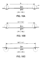
- Figs. 10A to 10C are views explaining characteristics of a diaphragm, among which Fig. 10A shows a pressure-free state, Fig. 10B shows a state in which the diaphragm is displaced by a differential pressure, and Fig. 10C shows a state in which the differential pressure is applied to the displaced diaphragm in a direction opposite to the direction of the displacement.
- Figs. 11A to 11 B are explanatory views of the construction of a differential pressure-sensing section of the eighth embodiment of Fig. 9, among which Fig. 11A shows a case where discharge pressure Pdh 2 is higher than an outlet port pressure Pdl, and Fig. 11 B shows a case where the discharge pressure Pdh 2 is lower than outlet port pressure Pdl.
- the control valve 10 (first embodiment, Figs 1 and 2) for a variable displacement compressor comprises a first control valve 10A that controls a passage cross-sectional area of a refrigerant passage between a discharge chamber of the compressor and a refrigerant outlet port, a second control valve 10B that controls the flow rate between the discharge chamber and a crankcase, and a solenoid section 10C that sets the passage cross-sectional area of the refrigerant passage of the first control valve 10A, all of which are arranged on the same axis.
- the first control valve 10A and the second control valve 10B have a first body 11 and a second body 12 press-fitted into the first body 11.
- the first body 11 and the second body 12 are provided with ports 13, 14, and 15.
- the ports 13, 14, and 15 are communicated respectively with the discharge chamber, for introducing discharge pressure Pdh into port 13" with the refrigerant outlet port, for discharging discharge pressure Pdl, and again with the discharge chamber, for introducing discharge pressure Pdh2 into port 15.
- the second body 12 has another port 16 communicating with the crankcase, for discharging pressure Pc.
- the control valve 10 can be applied to a compressor configured such that the port 13 at the discharge pressure Pdh and the port 15 at the discharge pressure Pdh2 both communicate with the discharge chamber.
- the control valve 10 is applied to a compressor such that the port 13 at discharge pressure Pdh directly communicates with the discharge chamber, and the port 15 at discharge pressure Pdh2 communicates with an outlet port of an oil separator disposed on the downstream side of the discharge chamber. This enables the second control valve 10B to return compressor lubricating oil, contained the in refrigerant in a large amount, while controlling pressure Pc.
- the first control valve 10A has an axial passage through the second body 12 between the ports 13, 14.
- a first valve seat 17 is press-fitted in the passage, and a first valve element 18 is movably disposed downstream of the first valve seat 17.
- the first valve element 18 has a hollow integral cylindrical portion axially extending through a valve hole.
- a guide 19 is rigidly press-fitted in the hollow cylindrical portion.
- the guide 19 is urged by a spring 20 in valve-closing direction of the first control valve 10A.
- a portion of the guide 19 is in sliding contact with an inner wall of the first body 11 and has an outer diameter equal to the inner diameter of the first valve seat 17, whereby discharge pressure Pdh from port 13 equally acts on the first valve element 18 and the guide 19 in opposite directions to prevent that the discharge pressure Pdh adversely affects control operations of the first control valve 10A.
- the guide 19 forms an axial refrigerant passage, and is equipped with a check valve 21 for opening and closing the refrigerant passage.
- the check valve 21 has a valve element 22, e.g. made of rubber, disposed on a low-pressure side or port 14 of the refrigerant passage and a leaf spring 23 axially movably holding the valve element 22. In a neutral pressure-free state the valve element 22 is held by the leaf spring at a position where the refrigerant passage is slightly open.
- the second control valve 10B has a second valve seat 31 press-fitted into the foremost end of the second body 12, where the axial port 16 is formed, and a second movable valve element 32 upstream of the second valve seat 31.
- the second valve element 32 is axially movably guided and captured by a piston 33 forming a differential pressure-sensing section which in turn is axially guided by the second body 12.
- the piston 33 has a recessed valve element base portion-accommodating portion 34 opposed to the second valve seat 31, containing a spring 35 and a base portion of the second valve element 32.
- An open end of the accommodating portion 34 is swaged to hold back the second valve element 32. This makes it possible to soften collision impacts between the second valve element 32 and the second valve seat 31 when the second control valve 10B closes quickly.
- the piston 33 is urged in valve-closing direction of the second control valve 10B by a spring 37 between the piston 33 and a spring-receiving portion 36 press-fitted into the second body 12.
- the spring 37 has a smaller spring force than the spring 20.
- the piston 33 has an integral extended portion 38 toward the solenoid section 10c and into the first valve element 18.
- a washer 39 fixed to an end of the extended portion 38, e.g. by swaging, is brought into engagement with a stepped portion formed on the first valve element 18.
- the second control valve 10B has film-like seal rings 40 and 41, formed e.g. of rubber, for sealing clearances between the piston 33 and the second body 12 by the pressures in the ports 14, 15.
- the seal rings 40 and 41 are arranged between a stepped portion of the second body 12 and the spring-receiving portion 36 and between a stepped portion of the second body 12 and the second valve seat 31, respectively.
- the solenoid section 10c has a fixed core 51 in a central opening of the first body 11 and fitted into an opening of a bottomed sleeve 52 in a manner blocking the opening.
- the bottomed sleeve 52 contains a plunger 53, a shaft 54 axially extending through the core 51 and rigidly fixed to the plunger 53, an adjustment member 55 disposed on the bottom of the bottomed sleeve 52 for axially plastically deforming the bottom, thereby adjusting spring loads, a spring 56 between the core 51 and the plunger 53, and a spring 57 between the plunger 53 and the adjustment member 55.
- the shaft 54 is axially movably guided by the core 51 and the plunger 53, with a free end extending into the guide 19.
- the free shaft end abuts at an intercommunicating plate 24 fitted into the guide 19 on a side opposite from the check valve 21, for urging the first valve element 18 in valve-opening direction of the first control valve 10A.
- the bottomed sleeve 52 is surrounded by a coil 58 and a yoke 59.
- O-rings 61, 62, 63, 64 are provided for sealing between the ports 13, 14, the ports 14, 15, the ports 15, 16, and the port 13 and the atmosphere, respectively, when the control valve 10 is mounted in the compressor.
- the solenoid section 10C When the solenoid section 10C is de-energized, as shown in Fig. 1, while the compressor is operating, the first control valve 10A is forcibly fully closed by the spring 20, and the second control valve 10B is fully open since the piston 33 is pulled in valve-opening direction against the spring 37 by the first valve element 18. All the discharged refrigerant is introduced into the crankcase via the second control valve 10B, and the compressor is in the minimum displacement operation state.
- the control valve 10 thus can be applied to a variable displacement compressor without an electromagnetic clutch between the compressor and the driving engine.
- control current is supplied to the solenoid section 10C.
- the plunger 53 is pulled by the core 51, whereby the first valve element 18 is pushed upward by the shaft 54, as viewed in Fig. 1.
- the piston 33 of the second control valve 10B, engaged with the first valve element 18, is also pushed upward, as viewed in Fig. 1, by the spring 37, until the second valve element 32 is seated on the second valve seat 31 to fully close the second control valve 10B. Since the refrigerant discharged ceases to be introduced into the crankcase, the compressor is now shifting to the maximum displacement operation.
- the first valve element 18 is stopped at a position where the urging force of the solenoid section and the force of the spring 20 are balanced. This position does not change until the value of the control current is changed.
- the piston 33 senses the change in the differential pressure to further open the second control valve 10B. This controls the compressor in a direction of decreasing the displacement.
- the piston 33 senses the change in the differential pressure to shift the second control valve 10B in valve-closing direction. This controls the compressor in a direction of increasing the displacement.
- the second control valve 10B controls the flow rate to the crankcase such that the differential pressure ⁇ P is held constant.
- the control valve 10 controls the compressor such that refrigerant is discharged at the flow rate corresponding to the value of the control current supplied to the solenoid section 10C.
- the first control valve 10A is held fully-closed since the discharge pressure Pdl acts on the first valve element 18 and the check valve 21 in valve closing directions, while the second control vale 10B is fully-open without being actuated by the discharge pressure Pdl since the piston 33 and the first valve element 18 have the same pressure-receiving areas. Leakage from the port 14 to the port 15 via the clearance between the second body 12 and the piston 33 is blocked by the seal ring 40.
- the first control valve 10A can be held in the fully-closed state, to act similarly to the check valve which conventionally has to be provided in the refrigerant outlet port.
- the second control valve 10B is fully-open, such that the compressor positively shifts to minimum displacement operation.
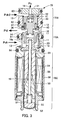
- the control valve 70 in Fig. 3 differs from the first embodiment in that the check valve 21 of Figs 1, 2 is omitted.
- a first control valve 70A the guide 19 connected to the first valve element 18 comprises a hollow cylindrical portion having a closed end, and an integral sliding portion, and a radially outwardly extending flange at an open end of the hollow cylindrical portion. An outer peripheral surface of the flange slides on an inner wall surface of the first body 11.
- the shaft 54 of a solenoid section 70C extends into the hollow cylindrical portion for abutment at the closed end.
- the guide 19 has an intercommunicating hole 19a formed in a side wall such that pressure in the solenoid section 70C always equals the discharge pressure Pdh upstream of the first control valve 70A.
- the flow rate through the first control valve 70A increases.
- the piston 33 that senses the differential pressure acts to open the second control valve 70B to make the displacement of the compressor variable.
- the solenoid section 70C is de-energized when the control valve 70 is in the control state, the first control valve 70A is fully closed instantaneously by the spring 20, and the second control valve 70B is constrained and forcibly fully opened during transition of the first control valve 70A to the fully-closed state.
- the first valve element 18 and the integrated piston 33 have the same pressure-receiving area, and hence are insensitive to the discharge pressure Pdl, so that even if the discharge pressure Pdl exceeds the discharge pressure Pdh, both the fully-closed state of the first control valve 70A and the fully-open state of the second control valve 70B are maintained.
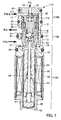
- the control valve 80 in Fig. 4 differs from the of the first and second embodiments by a simplified construction, namely by forming the two ports 13 and 15 into a common port.
- a first control valve 80A has the first valve element 18 upstream of the first valve seat 17.
- the first valve element 18 has an axial through hole and a hollow cylindrical portion 81 extending via a valve hole is rigidly press-fitted into the through hole.
- the hollow cylindrical portion 81 is integral with a piston 82 axially slidably disposed within the first body 11.
- a hollow part of the hollow cylindrical portion 81 extends into the piston 82 such that the hollow part communicates with a side opposite to the side where the hollow cylindrical portion 81 is formed, and the hollow part extending through the piston 82 forms a refrigerant passage 83 through which the discharge pressure Pdh is introduced into the solenoid section 80C.
- the piston 82 is urged in valve-closing direction by the spring 20 between the piston 82 and an end face of the second body 12.
- the piston 82 has a large outer diameter on the side toward a second control valve 80B, such that the first control valve 80A defines a valve structure in which when the force of the spring 20 exceeds the force of the solenoid section 80C, the clearance between the first body 11 and the piston 82 is sealed.
- the axial central port 16 in the second body 12 forms by an inner open end a second valve seat port.
- the movable second valve element 32 is integral with a hollow cylindrical body 84 axially slidably disposed within the second body 12.
- the hollow cylindrical body 84 has the same outer diameter as the piston 82 of the first control valve 80A, has a plurality of intercommunicating holes, and has the first valve seat 17 rigidly press-fitted into the inside.
- the spring 37 between the first valve seat 17 and the piston 82 urges the hollow cylindrical body 84 in valve-closing direction of the second control valve 80B.
- the shaft 54 of the solenoid section 80C pushes the piston 82 of the first control valve 80A upward.
- the movable parts of the first and second control valves 80A, 80B move in unison in valve-closing direction of the second control valve 80B.
- the compressor shifts to the maximum displacement operation state.
- the piston 82 is pushed in valve-closing direction of the second control valve 80B, the first valve element 18 is progressively lifted from the first valve seat 17 to progressively open the first control valve 80A. Subsequently, the first valve element 18 stops at a lift position corresponding to the value of the control current.
- the first control valve 80A defines a passage cross-sectional area corresponding to the control current.
- the flow rate through the first control valve 80A increases and generates a differential pressure which is received by the cross-sectional areas of the first valve seat 17 and the hollow cylindrical body 84 forming a differential pressure-sensing section.
- the differential pressure becomes equal to or larger than a predetermined value, the first valve seat 17 and the hollow cylindrical body 84, open the second control valve 80B to make the displacement of the compressor variable.
- the second control valve 80 when the discharge pressure Pdh increases while the compressor is being controlled at a predetermined displacement, the second control valve 80 operates in valve-opening direction to control the capacity in a decreasing direction.
- the second control valve 80B When the discharge pressure Pdh decreases, the second control valve 80B operates in valve-closing direction to control the capacity in increasing direction.
- the first control valve 80A as well responds in accordance with the change of the discharge pressure Pdh, the displacement of the compressor is determined in dependence on the control balance between the first and second control valves 80A, 80B, an d is substantially set to a predetermined displacement.
- the solenoid section 80C is suddenly de-energized while the control valve 80 is in the control state, the first control valve 80A is fully closed instantaneously by the spring 20, and the second control valve 80B is constrained and forcibly fully opened during transition of the first control valve 80A to the fully-closed state.
- the pressure-receiving area at which the first valve set 17, the first valve element 18, and the hollow cylindrical body 84, which are integrally engaged with each other, receive the discharge pressure Pdl in upward direction is the same as the pressure-receiving area at which the piston 82 receives the discharge pressure Pdl in downward direction so that the control valve 80 has a structure which is operatively insensitive to the discharge pressure Pdl. Accordingly, even if the discharge pressure Pdl exceeds the discharge pressure Pdh, the fully-closed state of the first control valve 80A and the fully-open state of the second control valve 80B are maintained.
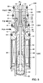
- the control valve 90 in Fig. 5 differs from the third embodiment by a higher response speed when returning again to the control state after suddenly transitioning from the control state to the stopped state.
- the valve element 18 and the integrated hollow cylindrical portion 81 define the linearly axial refrigerant passage 83.
- the hollow cylindrical portion 81 fixed to the piston 82 extends through the piston 82 such that an open end of the refrigerant passage 83 on the solenoid section can be opened and closed by an end face of the shaft 54.
- the control valve 90 thus has a valve structure in which when the solenoid section 90C is de-energized (Fig. 5), the port 13 (discharge pressure Pdh) and the solenoid section 90C communicate with each other, whereas when the solenoid section 90C is energized, the communication between the port 13 and the inside of the solenoid section 90C is blocked.
- the second valve seat 31 at the port 15 for the discharge pressure Pdh2 is formed on the foremost end of the second body 12.
- the second valve element 32 is axially movably guided in the second body 12.
- a lower end of the second valve element 32 extends into a chamber of the port 13 (discharge pressure Pdh).
- An engaging portion 101 held by a closing portion of the hollow cylindrical body 84 of the first control valve 100A is rigidly press-fitted on the lower end of the second valve element 32.
- the spring 35 between the engaging portion 101 and the first valve element 18 urges the second valve element 32 in valve-closing direction.
- An upper end face of the engaging portion 101 5 is tapered to close the clearance between the second valve element 32 and the second body 12 when the second valve element 32 is seated on the second valve seat 31.
- a second control valve 100B is configured such that both discharge pressures Pdh, Pdh2, which are approximately equal, are applied to axially opposite ends of the second valve element 32, respectively.
- the control valve 100 performs control operation in response to a differential pressure between the pressures as applied to the first valve seat 17 and the hollow cylindrical body 84 from axially opposite sides, without being adversely affected by the pressure Pc.
- the first control valve 110A and the solenoid section 110C are very similar to the first embodiment but the second control valve 110B has a different construction.
- the differential pressure-sensing section is formed by a valve element-holding portion 111 that holds the second valve element 32 and a bellows 112. Axially opposite ends of the bellows 112 are tightly connected to an upper end of the valve element-holding portion 111 and to an upper end of the spring-receiving portion 36 such that the bellows 112 can expand and contract axially.
- the valve element-holding portion 111 similarly to the piston 33 of the second control valve 10B in the first embodiment, the valve element-holding portion 111 causes the second valve element 32 to axially move according to a differential pressure between the discharge pressures Pdh, 2 Pdl, whereby the valve lift of the second control valve 1108 can be adjusted. Since the bellows 112 defines a partition between the ports 15, 14 it is possible to completely prevent leakage by the differential pressure between the pressures Pdh2 and Pdl, without the seal rings 40 and 41.
- the control valve 120 of Fig. 8 differs from the second embodiment by a simpler construction.
- a first control valve 120A both ends of the first valve element 18 and the guide 19 slidingly contact the inner walls of the first body 11 and the second body 12.
- the guide 19 has a communication hole 121 in a top portion close to the location where the shaft 54 of the solenoid section 120C abuts.
- a second control valve 120B includes the piston 33 that senses the differential pressure between the discharge pressure Pdh2 at the port 15 and the discharge pressure Pdl at the port 14.
- a shaft 122 is fixed to the piston 33.
- One end of the shaft 122 forms the second valve element 32 of the second control valve 120B, while the other end forms an engaging portion for the first valve element 18 when when the solenoid section 120C is de-energized to cooperate with the first valve element 18 to form a valve element of a valve that opens and closes the axial refrigerant passage of the first valve element 18 and the guide 19.
- the spring 37 urging the piston 33 in valve-closing direction of the second control valve 120B is disposed between the seal ring 40 and the first valve element 18 of the first control valve 120A. Although the spring 37 should urge the piston 33 relative to the second body 12, the spring is arranged to urge the piston 33 relative to the first valve element 18 so as to reduce a needed spring load and to simplify the construction.
- the shaft 54 pushes the first valve element 18 via the guide 19 upward to open the first control valve 120A.
- the piston 33 as well is pushed upward by the spring 37 interlocked with the pushing action for the first valve element 18.
- the second control valve 120B is fully closed.
- the shaft 122 first tightly engaged with the first valve element 18 looses contact with the first valve element 18, so that the refrigerant passage through the first valve element 18 and the guide 19 is opened.
- the solenoid section 120C communicates with the port 14 to equalise the pressures.
- the discharge pressures Pdh and Pdh2 which have been sharply decreased to become approximately equal to each other, are applied to the axially opposite ends of the movable part of the guide 19, the first valve element 18, and the piston 33, which are made integral with each other, and therefore the fully-closed state of the first control valve 120A and the fully-open state of the second control valve 120B are maintained almost only by the load of the spring 20.
- the control valve 130 of Fig. 9 (eighth embodiment) is constructed by using lower-cost component parts in place of the high-cost bellows 112 used in the the sixth embodiment, and in place of high-cost cut parts used in the seventh embodiment.
- Almost all component elements of a first control valve 130A and a second control valve 130B are pressed parts formed by pressing pipes, and the pressed parts are assembled by press-fitting or swaging.
- a first body 131 having an inwardly bent end is fixed to a solenoid section 130C by swaging the foremost end of the core 51 protruding from the yoke 59.
- a second body 132 and a third body 133 having one end forming the first valve seat 17 are rigidly press-fitted into the first body 131.
- the third body 133 axially guides the here bell-shaped guide 19.
- a bell-shaped shaft-receiving portion 134 having the communication hole 121 is press-fitted into the guide 19.
- the guide 19 carries the fixed first valve element and is urged in valve-closing direction by the spring 20 between a flange end and a protrusion formed on the inside of the body 133.
- the second body 132 has an open end containing a diaphragm 135, e.g. made of polyimide, sealing between the port 15 (discharge pressure Pdh2) and the port 14 (discharge pressure Pdl).
- the diaphragm 135 senses the differential pressure between the discharge pressures Pdh2 and Pdl, and has an outer peripheral portion sandwiched between first and second rings 136, 137 A central diaphragm portion is sandwiched between a centre disk 138 and a flange portion 139.
- the first and second rings 136, 137 are fixed to the second body 132 together with a fourth body 140 by swaging open ends of the second body 132, sandwiching the diaphragm 135 therebetween.
- the centre disk 138 and the flange portion 139 are fixed to each other sandwiching the diaphragm 135 therebetween, by press-fitting a shaft 141 into a central portion of the centre disk 138 and the hollow cylindrical second valve element 32 of the second control valve 130B, integrally formed with the flange portion 139.
- portions of the first and second rings 136 and 137, sandwiching the outer peripheral portion and the central portion of the diaphragm 135, are configured such that the inner diameter of the first ring 136 is larger than the inner diameter of the second ring 137, and the outer diameter of the centre disk 138 is larger than the outer diameter of the flange portion 139.
- the first ring 136 has a stepped portion, and a portion thereof forms a stopper 142 restricting the displacement of the diaphragm 135.
- a cup-shaped fifth body 143 is press-fitted into the fourth body 140.
- the fifth body 143 has a valve hole of the second control valve 130B formed in the centre of the bottom. An opening of the valve hole forms the port 16 leading to the crankcase.
- the shaft 141 extends through the valve hole of the second control valve 130B, and a spring-receiving portion 144 is externally fitted on a foremost end of the shaft 141. Interposed between the bottom of the fifth body 143 and the spring-receiving portion 144 is the spring 37 which urges the second valve element 32 in valve-closing direction.
- the shaft 54 pushes the first valve element 18 via the guide 19 upward to open the first control valve 130A.
- the shaft 141 as well is pulled upward by the spring 37, interlocked with the upward pushing action of the first valve element 18.
- the second control valve 130B is fully closed.
- the shaft 141 first tightly engaged with the guide 19 loses the sealing engagement with the guide 19, so that the solenoid section 130C communicates via a hole in the centre of the guide 19, through which the shaft 141, and the communication hole 121 of the shaft-receiving portion 134 with the port 14.
- Pressure in the solenoid section 130C becomes equal to the discharge pressure Pdl.
- the first valve element 18 stops at a position where the urging force of the solenoid section 130C corresponding to the predetermined current value and the spring 20 are balanced.
- the first valve element 18 is lifted from the first valve seat 17 and is stopped.
- the refrigerant passage of the first control valve 130A has a predetermined passage cross-sectional area, so that the discharge pressure Pdh, from the port 13, passes through the refrigerant passage the discharge pressure Pdl is discharged from the port 14 into the compressor refrigerant outlet port. Then a predetermined differential pressure ⁇ P is generated across the first control valve 130A.
- the differential pressure ⁇ P is sensed by the diaphragm 135, which drives the second valve element 32 which in turn controls the flow rate via the second control valve 130B to the crankcase.
- the compressor discharge flow rate corresponds to the value of the control current.
- the effective pressure-receiving area of the diaphragm 135 varies according to the displacement stroke of the diaphragm. As shown in Fig. 10A, the effective pressure-receiving area of the diaphragm 135 depends on the area of a circle a diameter (effective diameter b) of which is the distance between the centres of curvature circles a of respective corrugated portions.
- a diameter effective diameter b
- Fig. 10B when the pressure P1 applied from above becomes higher than the pressure P2 applied from below a central portion of the diaphragm 135 is displaced downward (Fig. 10B).
- each corrugated portion Since an inner peripheral portion of each corrugated portion is also displaced together with the central portion, the curvature of the corrugated portion is increased, and the centre of the curvature moves inward, whereby the effective diameter becomes an effective diameter b1 smaller than the effective diameter b.
- This action decreases the effective pressure-receiving area.
- FIG. 10C when the pressure P2 exceeds the pressure P1 in a state in which the central portion of the diaphragm 135 is displaced, the corrugated portion alone expands to swell toward the side of the pressure P1, which causes the centre of the curvature to move outward such that the effective diameter becomes an effective diameter b2 larger than the effective diameter b. This action increases the effective pressure-receiving area.
- This situation corresponds to the case where the control current is suddenly switched off to make the discharge pressure Pdl downstream of the first control valve 130A higher than the discharge pressure Pdh2 upstream.
- the second valve element 32 moving in unison with the diaphragm 135 is caused by the differential pressure between the discharge pressures Pdl and Pdh2 to act in the valve-closing direction. More specifically, when the solenoid section 130C is de-energized, the second control valve 130B is fully opened by the spring 20, but immediately after that, when the discharge pressure Pdl exceeds the discharge pressure Pdh2, the diaphragm 135 which is responsive to the differential pressure acts on the second control valve 130B in valve-closing direction. Therefore, particularly when the value of the differential pressure is large, it would be impossible to maintain the fully-closed state of the first control valve 130A and the fully-open state of the second control valve 130B.
- control valve 130 is configured such that when the discharge pressure Pdl exceeds the discharge pressure Pdh2, the force that acts on the second control valve 130B in valve-closing direction is inhibited from increasing.
- an effective diameter c2 of the diaphragm 135 obtained when the discharge pressure Pdl is higher than the discharge pressure Pdh2 is made smaller than an effective diameter c1 of the diaphragm 135 obtained when the discharge pressure Pdh2 is higher than the discharge pressure Pdl.
- This is realized, as shown in FIGS. 11A and 11B, by making the respective inner diameters of the first and second rings 136 and 137 different, and by making the outer diameters of the centre disk 138 and the flange portion 139 different.
- the inner diameter of the stepped portion of the first ring 136 is larger than the inner diameter of the second ring 137, and the outer diameter of the centre disk 138 is larger than that of the flange portion 139.
- the effective diameter c1 is equal to the inner diameter of the first valve seat of the first control valve 130A such that when the first control valve 130A is closed, the diaphragm 135 has the same pressure-receiving area as the first valve element 18 for the discharge pressure Pdl.
- the distance between the inner periphery of the first ring 136 and the outer periphery of the centre disk 138 is equal to the distance between the inner periphery of the second ring 137 and the outer periphery of the flange portion 139.
- the corrugated portion of the diaphragm 135 is defined by the centre disk 138 having a larger outer diameter and the first ring 136 having a larger inner diameter, and the effective pressure-receiving area of the diaphragm 135 at this time is determined by the effective diameter c1.
- Pdl > Pdh2 holds, as shown in FIG. 11B.
- the corrugated portion of the diaphragm 135 is defined by the flange portion 139 having a smaller outer diameter and the second ring 137 having a smaller inner diameter, and the effective pressure-receiving area of the diaphragm 135 at this time is determined by the effective diameter c2.
- the effective pressure-receiving area of the diaphragm 135 is changed to be smaller. This reduces the force acting by the differential pressure on the second control valve 130B in valve-closing direction. A stopping operation of the automotive air conditioner may then be performed smoothly.
Landscapes
- Engineering & Computer Science (AREA)
- Mechanical Engineering (AREA)
- General Engineering & Computer Science (AREA)
- Compressors, Vaccum Pumps And Other Relevant Systems (AREA)
- Control Of Positive-Displacement Pumps (AREA)
- Magnetically Actuated Valves (AREA)
Applications Claiming Priority (3)
| Application Number | Priority Date | Filing Date | Title |
|---|---|---|---|
| JP2006004395 | 2006-01-12 | ||
| JP2006039365 | 2006-02-16 | ||
| JP2006238904A JP4923186B2 (ja) | 2006-01-12 | 2006-09-04 | 可変容量圧縮機用制御弁 |
Publications (1)
| Publication Number | Publication Date |
|---|---|
| EP1808601A2 true EP1808601A2 (de) | 2007-07-18 |
Family
ID=37897416
Family Applications (1)
| Application Number | Title | Priority Date | Filing Date |
|---|---|---|---|
| EP07000519A Withdrawn EP1808601A2 (de) | 2006-01-12 | 2007-01-11 | Regelventil für einen Verdichter variabler Verdrängung |
Country Status (4)
| Country | Link |
|---|---|
| US (1) | US20070157648A1 (de) |
| EP (1) | EP1808601A2 (de) |
| JP (1) | JP4923186B2 (de) |
| KR (1) | KR20070075332A (de) |
Families Citing this family (2)
| Publication number | Priority date | Publication date | Assignee | Title |
|---|---|---|---|---|
| JP2012091578A (ja) * | 2010-10-25 | 2012-05-17 | Tgk Co Ltd | 車両用冷暖房装置および集合弁 |
| JP2015183614A (ja) * | 2014-03-25 | 2015-10-22 | 株式会社豊田自動織機 | 可変容量型斜板式圧縮機 |
-
2006
- 2006-09-04 JP JP2006238904A patent/JP4923186B2/ja not_active Expired - Fee Related
-
2007
- 2007-01-05 US US11/649,923 patent/US20070157648A1/en not_active Abandoned
- 2007-01-11 EP EP07000519A patent/EP1808601A2/de not_active Withdrawn
- 2007-01-11 KR KR1020070003097A patent/KR20070075332A/ko not_active Withdrawn
Also Published As
| Publication number | Publication date |
|---|---|
| JP4923186B2 (ja) | 2012-04-25 |
| JP2007247640A (ja) | 2007-09-27 |
| KR20070075332A (ko) | 2007-07-18 |
| US20070157648A1 (en) | 2007-07-12 |
Similar Documents
| Publication | Publication Date | Title |
|---|---|---|
| JP7171616B2 (ja) | 容量制御弁及び容量制御弁の制御方法 | |
| JP7118568B2 (ja) | 容量制御弁及び容量制御弁の制御方法 | |
| EP3575647B1 (de) | Ventil zur kapazitätssteuerung | |
| EP2733351B1 (de) | Verbundventil | |
| EP1059443B1 (de) | Kapazitätskontrollventil | |
| US20060218953A1 (en) | Control valve for variable displacement compressor | |
| US6662582B2 (en) | Displacement control valve | |
| EP1247981A2 (de) | Kontrollventil für Kompressoren mit variabler Fördermenge | |
| US6302656B1 (en) | Solenoid controlled valve and variable displacement compressor | |
| KR20140056097A (ko) | 제어 밸브 | |
| EP1512871A1 (de) | Kontrollventil für einen verstellbaren Taumelscheibenkompressor | |
| US20040086391A1 (en) | Control valve for variable displacement compressor | |
| JPWO2019142931A1 (ja) | 容量制御弁 | |
| EP1574710B1 (de) | Regelventil für einen Kompressor mit veränderlicher Verdrängung | |
| EP1605161A2 (de) | Kontrolventil für einen verstellbaren Taumelscheibenkompressor | |
| EP1602828A2 (de) | Kontrollventil für einen verstellbaren Taumelscheibenkompressor | |
| US6783332B2 (en) | Control valve of variable displacement compressor with pressure sensing member | |
| EP1808601A2 (de) | Regelventil für einen Verdichter variabler Verdrängung | |
| EP1628017A2 (de) | Regelventil für einen Kompressor mit veränderlicher Verdrängung | |
| US20060045758A1 (en) | Control valve for variable displacement compressor | |
| EP1637736A2 (de) | Regelventil für einen Verdichter variabler Verdrängung | |
| EP1630418B1 (de) | Kontrollventil für einen verstellbaren Taumelscheibenkompressor | |
| EP3584441B1 (de) | Ventil zur kapazitätssteuerung | |
| JP7139075B2 (ja) | 容量制御弁及び容量制御弁の制御方法 | |
| JP2024046023A (ja) | 制御弁 |
Legal Events
| Date | Code | Title | Description |
|---|---|---|---|
| PUAI | Public reference made under article 153(3) epc to a published international application that has entered the european phase |
Free format text: ORIGINAL CODE: 0009012 |
|
| AK | Designated contracting states |
Kind code of ref document: A2 Designated state(s): AT BE BG CH CY CZ DE DK EE ES FI FR GB GR HU IE IS IT LI LT LU LV MC NL PL PT RO SE SI SK TR |
|
| AX | Request for extension of the european patent |
Extension state: AL BA HR MK YU |
|
| STAA | Information on the status of an ep patent application or granted ep patent |
Free format text: STATUS: THE APPLICATION HAS BEEN WITHDRAWN |
|
| 18W | Application withdrawn |
Effective date: 20081124 |