EP1808521A1 - Improvement in the air circulation system of a household-type clothes dryer - Google Patents
Improvement in the air circulation system of a household-type clothes dryer Download PDFInfo
- Publication number
- EP1808521A1 EP1808521A1 EP06100344A EP06100344A EP1808521A1 EP 1808521 A1 EP1808521 A1 EP 1808521A1 EP 06100344 A EP06100344 A EP 06100344A EP 06100344 A EP06100344 A EP 06100344A EP 1808521 A1 EP1808521 A1 EP 1808521A1
- Authority
- EP
- European Patent Office
- Prior art keywords
- drum
- wall
- flow
- conduit
- drying
- Prior art date
- Legal status (The legal status is an assumption and is not a legal conclusion. Google has not performed a legal analysis and makes no representation as to the accuracy of the status listed.)
- Granted
Links
- 238000001035 drying Methods 0.000 claims abstract description 48
- 238000010438 heat treatment Methods 0.000 claims description 7
- 238000005406 washing Methods 0.000 claims description 3
- 238000000034 method Methods 0.000 description 5
- XLYOFNOQVPJJNP-UHFFFAOYSA-N water Substances O XLYOFNOQVPJJNP-UHFFFAOYSA-N 0.000 description 4
- 238000010276 construction Methods 0.000 description 3
- 230000000694 effects Effects 0.000 description 3
- 238000001816 cooling Methods 0.000 description 2
- 238000007664 blowing Methods 0.000 description 1
- 230000000052 comparative effect Effects 0.000 description 1
- 238000009833 condensation Methods 0.000 description 1
- 230000005494 condensation Effects 0.000 description 1
- 239000000463 material Substances 0.000 description 1
- 239000002184 metal Substances 0.000 description 1
- 239000007787 solid Substances 0.000 description 1
Images


Classifications
-
- D—TEXTILES; PAPER
- D06—TREATMENT OF TEXTILES OR THE LIKE; LAUNDERING; FLEXIBLE MATERIALS NOT OTHERWISE PROVIDED FOR
- D06F—LAUNDERING, DRYING, IRONING, PRESSING OR FOLDING TEXTILE ARTICLES
- D06F58/00—Domestic laundry dryers
- D06F58/02—Domestic laundry dryers having dryer drums rotating about a horizontal axis
- D06F58/04—Details
-
- D—TEXTILES; PAPER
- D06—TREATMENT OF TEXTILES OR THE LIKE; LAUNDERING; FLEXIBLE MATERIALS NOT OTHERWISE PROVIDED FOR
- D06F—LAUNDERING, DRYING, IRONING, PRESSING OR FOLDING TEXTILE ARTICLES
- D06F58/00—Domestic laundry dryers
- D06F58/02—Domestic laundry dryers having dryer drums rotating about a horizontal axis
Definitions
- the present invention refers to an improved kind of clothes drying machine, preferably a tumble dryer of the type intended for use in households, provided with means for removing moisture from the drying air comprising a conduit, through which there is conveyed a flow of hot, relatively dry air for entering a rotating drum in which there have preliminarily been introduced the clothes forming the load to be dried.
- this flow of hot air moves through and over the clothes to be dried and is eventually caused to exit the drum to be either let out into the atmosphere, or the ambient, or re-circulated in a closed-loop circuit, in which said flow of hot and, at this point, moisture-laden air is dehumidified, heated up again to drying temperature and blown again into the drum.
- the clothes dryer As far as the present invention is concerned, it is of no importance at all for the clothes dryer to be of a particular kind, i.e. of the first-named kind, or exhaust type letting out the air directly into the ambient, or the second-named kind provided with condenser arrangement.
- the clothes dryer is of a particular kind, i.e. of the first-named kind, or exhaust type letting out the air directly into the ambient, or the second-named kind provided with condenser arrangement.
- what really matters to the purposes of the present invention is the presence of a rotating drum holding the load of clothes to be dried, into which a flow of hot drying air is blown for removing the moisture contained in the clothes, and from which this air is eventually caused to flow out to be either exhausted or conveyed to the condensation process for reuse.
- the present invention preferably applies to clothes drying machines that, further to a condenser for dehumidifying the hot moisture laden air exiting the drum, are also provided with:
- the present invention shall be understood as applying equally well to condenser-type clothes dryers of a traditional kind, i.e. provided with a normal condenser, but lacking the other features as mentioned above.
- the vapour generated in this way is then immediately taken in by and mixed in the drying air flowing therethrough, so that it automatically leaves the drum, since said flow of drying air is practically taken out of the drum continuously.
- extension duct conveys the heated-up air directly into the central portion of the drum, so as to increase the amount of clothes in the drying load being directly exposed thereto.
- the resulting direct heating effect is quite appreciable, since heating by direct conduction between the preferably metal surface of said extension duct and the items to be dried is generally known to be more efficient than heating by convection, i.e. the heating effect brought about by the hot air flowing through the drum.
- the amount of solid surface materially existing between adjacent perforations in the extension duct adds up to just a relatively small value, so that the amount of heat that is exchanged by conduction between the same extension duct and the items to be dried coming in contact therewith is reduced correspondingly.
- this clothes drying machine shall be capable of accommodating such improved features, without any significant penalty having to be paid in exchange for this as far as other construction and performance aspects or functions are concerned.
- the conduit 2 contains a respective fan 5 for moving the flow of drying air, as well as a respective heating element 9 for heating up said drying air.
- Said conduit upon extending along a flow-path that will be described in greater detail further on, terminates in a plurality of air-outlet ports 3 opening up directly inside the drum.
- this conduit 2 does not solely and strictly consist of a specific physical duct, but rather includes all material elements that are altogether used and provided to direct the flow of drying air from the fan 5 up to said outlet ports 3.
- said conduit is led to extend well into the drum 1 with en extension piece 4 provided thereinside and attached to the rear wall 16 of said drum in a substantially axial arrangement (fig. 2).
- This extension piece 4 appears externally in the shape of a cylinder provided with an outer wall 10 terminating - on the free side thereof inside the drum - in a closed wall 11 that is situated at a pre-determined distance D from the rear wall 16 of the drum from which said extension piece departs.
- a second cylinder 12, or inner wall that is spaced, i.e. separated from the outer surface of said extension piece 4 and preferably extends coaxially therewith.
- the innermost end portion 14 of said second cylinder 12 is fully open, so that the hollow interspace or jacket 13 forming between said outer wall 10 and said inner cylinder 12 is capable of joining into the inner space thereof simply via said inner end portion 14 delimiting said inner wall 12.
- said extension piece 4 is preferably firmly joined with the rotating body of the drum, so as to rotate jointly therewith. It can be readily appreciated that the passage of the air from said hollow interspace 13 to the downstream section of said conduit 2 is ensured by means of a plurality of perforations 17 provided in said rear wall 16, so as to ensure the required mechanical continuity between the outermost portion of the rear wall 16 and the innermost portion 16A, on which said outer wall 10 is applied.
- the flow of air is then directed further on by the conduit 2 towards a plurality of further perforations 18, which are also provided in the rear wall 16 of the drum, so as to definitively lead the flow of hot air into the drum.
- the above-described solution still has a drawback in that the necessarily limited diameter of the cylindrical extension piece 4 causes the flow of hot air flowing therethrough to suffer a pressure drop that can in turn cause the flow rate of the same air to decrease to such a low value as to practically impair the final performance capabilities of the machine.
- an advantageously modified embodiment which consists in having the conduit 2 subdivided into two branches operating in parallel in a functional and not physical sense, i.e. the hot air flowing through said conduit 2 is at a certain point split up and let into two separate ducts, wherein a first duct is readily directed into the drum, while the second duct is directed into the extension piece 4, at the outlet side of which the related air flow is in turn conveyed into the drum.
- This solution can be materially embodied as illustrated in the same figure 4, in which the second cylinder 12 is attached at the base thereof to the central portion 16A of the rear wall of the drum, whereas the outer wall 10 covers said second cylinder 12 in the way of a cap; the stream of hot air flows through said hollow interspace 13 by passing through - further to said open end portion 14 - also a plurality of third perforations 20 that are provided to fluidly connect the rear portion of said outer wall 10 with the interior of the drum 1.
Landscapes
- Engineering & Computer Science (AREA)
- Textile Engineering (AREA)
- Detail Structures Of Washing Machines And Dryers (AREA)
- Drying Of Solid Materials (AREA)
- Accessory Of Washing/Drying Machine, Commercial Washing/Drying Machine, Other Washing/Drying Machine (AREA)
Abstract
Said innermost end portion (14) of the inner wall (12) is situated at a predetermined distance (D) from said outer wall (10), so as to enable a flow of drying air to enter either from the hollow interspace (13) defined between said outer wall (10) and said inner wail (12), or the other way round.
Description
- The present invention refers to an improved kind of clothes drying machine, preferably a tumble dryer of the type intended for use in households, provided with means for removing moisture from the drying air comprising a conduit, through which there is conveyed a flow of hot, relatively dry air for entering a rotating drum in which there have preliminarily been introduced the clothes forming the load to be dried. In the drum, this flow of hot air moves through and over the clothes to be dried and is eventually caused to exit the drum to be either let out into the atmosphere, or the ambient, or re-circulated in a closed-loop circuit, in which said flow of hot and, at this point, moisture-laden air is dehumidified, heated up again to drying temperature and blown again into the drum.
- As far as the present invention is concerned, it is of no importance at all for the clothes dryer to be of a particular kind, i.e. of the first-named kind, or exhaust type letting out the air directly into the ambient, or the second-named kind provided with condenser arrangement. In fact, what really matters to the purposes of the present invention is the presence of a rotating drum holding the load of clothes to be dried, into which a flow of hot drying air is blown for removing the moisture contained in the clothes, and from which this air is eventually caused to flow out to be either exhausted or conveyed to the condensation process for reuse.
- While reference will be made throughout the following description to an autonomous clothes drying machine, i.e. a machine intended solely for drying clothes, the explanations and descriptions given below shall be of course be understood as applying equally, and therefore effectively, to a so-called washer-dryer, i.e. a combination machine for washing and drying clothes.
- The machines of the kind covered by the present invention are largely known in the art. They are for instance described, along with detailed argumentations of a technical nature concerning the advantages and the drawbacks of various design solutions and embodiments, in the
Italian patent application No. PN2003U000015 European patent application No. 04104117.9 - Anyway, the present invention preferably applies to clothes drying machines that, further to a condenser for dehumidifying the hot moisture laden air exiting the drum, are also provided with:
- two distinct fans for the drying air and the condenser cooling air, respectively,
- a single motor adapted to drive said two fans at the same time,
- wherein said motor is adapted to be controlled so as to selectively rotate in the two opposite directions.
- At any rate, the present invention shall be understood as applying equally well to condenser-type clothes dryers of a traditional kind, i.e. provided with a normal condenser, but lacking the other features as mentioned above.
- As all those skilled in the art are well aware of, the process by which the flow of hot air moving through the drum, and the clothes held therein, removes the moisture contained in the clothes is mainly due to the fact that the heat supplied by the air itself heats up the water contained in the clothes, thereby causing it to progressively evaporate.
- The vapour generated in this way is then immediately taken in by and mixed in the drying air flowing therethrough, so that it automatically leaves the drum, since said flow of drying air is practically taken out of the drum continuously.
- However, although quite effective and reliable, this process has a major drawback in that, even if the heat exchange process taking place between the hot drying air and the moisture contained in the clothes to be dried is certainly favoured by the fact that the drum keeps rotating continuously during the drying cycle, thereby increasing the fraction of drying load that is directly invested by, i.e. directly exposed to the hot air flowing therethrough, heat conduction between the flow of hot drying air and the water contained in the clothes to be dried, and due to be removed by said air, is largely known to be rather limited.
- As a result, in order to enable the whole amount of water present in the clothes to be caused to evaporate, the need arises for said flow of hot air to be allowed to circulate through the drum for an extended period of time, so as to make sure that every single item in the drying load is effectively exposed to and possibly passed through by said flow of hot air.
- The direct consequence of such constraint is a much longer drying time needed to achieve the desired results, accompanied by a loss in energy efficiency owing to the drying machine tending to dissipate outside a certain part of the heat generated thereinside, and this occurs in a manner that is substantially proportional to the length of the process time.
- In view of doing away with these drawbacks, known from the
patent publication EP 1 285 987 to LG ELECTRONICS INC. is the practice of providing inside the drum of a clothes dryer "an extension duct lengthened from the suction duct into the drum, for flowing the air supplied from the suction duct into the drum, and an exhaust duct connected to the other side of the drum, for exhausting air which dried clothes to the outside of the case". - In this way the possibility is given to improve the drying efficiency to a certain extent, since such "extension duct" conveys the heated-up air directly into the central portion of the drum, so as to increase the amount of clothes in the drying load being directly exposed thereto.
- In addition, although this feature is not mentioned in the above-cited patent publication, also the surface of said extension duct that is not affected by the plurality of air holes provided to let out the heated-up air from the interior of the extension duct and into the drum, is heated up by the drying air; as a result, when the items to be dried come into contact with this surface, they are heated up by it quite rapidly.
- The resulting direct heating effect is quite appreciable, since heating by direct conduction between the preferably metal surface of said extension duct and the items to be dried is generally known to be more efficient than heating by convection, i.e. the heating effect brought about by the hot air flowing through the drum.
- However, the above-mentioned effect is in this case curtailed to a quite appreciable extent by the fact that the air-outlet perforations provided all along the extension duct practically take up a considerable portion of the surface thereof, since they have to enable a remarkable portion of the hot air flowing through said duct to wholly and fully escape into the drum.
- As a result, the amount of solid surface materially existing between adjacent perforations in the extension duct adds up to just a relatively small value, so that the amount of heat that is exchanged by conduction between the same extension duct and the items to be dried coming in contact therewith is reduced correspondingly.
- It would therefore be desirable, and it is actually a main object of the present invention, to provide a clothes drying machine of a general kind, which is particularly efficient in the use of energy and is at the same time capable of ensuring quicker operating cycles.
- In addition, this clothes drying machine shall be capable of accommodating such improved features, without any significant penalty having to be paid in exchange for this as far as other construction and performance aspects or functions are concerned.
- According to the present invention, these aims, along with further ones that shall be described further on, are reached in a clothes drying machine incorporating the features as recited in the appended claims. Anyway, features and advantages of the present invention will be more readily understood from the description that is given below by way of nonlimiting example with reference to the accompanying drawings, in which:
- Figure 1 is a functional schematic view of a clothes dryer according to the prior art,
- Figure 2 is a functional schematic view of a clothes dryer according to an embodiment of the present invention;
- Figure 3 is a functional schematic view of a clothes dryer according to a second preferred embodiment of the invention,
- Figure 4 is an enlargement and a more descriptive view of the embodiment of fig. 3.
With reference to fig. 1, provided in a clothes drying machine according to a prior-art embodiment there is adrum 1 adapted to hold the clothes to be dried, to which there is associated aconduit 2 for circulating the flow of drying air. This conduit may possibly be extended to pass through acondenser arrangement 21, adapted to condense and, hence, remove the moisture contained in the hot drying air exiting the drum and flowing therethrough, wherein a flow of "cold" air, i.e. air that is taken in from the surrounding ambient and sent to the condenser via a respective conduit, is directed to at the same time flow through the condenser in view of cooling it. - Thereinside, the
conduit 2 contains arespective fan 5 for moving the flow of drying air, as well as arespective heating element 9 for heating up said drying air. - Said conduit, upon extending along a flow-path that will be described in greater detail further on, terminates in a plurality of air-
outlet ports 3 opening up directly inside the drum. - It should at this point be clearly and explicitly pointed out that this
conduit 2 does not solely and strictly consist of a specific physical duct, but rather includes all material elements that are altogether used and provided to direct the flow of drying air from thefan 5 up to saidoutlet ports 3. - According to the present invention, said conduit is led to extend well into the
drum 1 with en extension piece 4 provided thereinside and attached to therear wall 16 of said drum in a substantially axial arrangement (fig. 2). - This extension piece 4 appears externally in the shape of a cylinder provided with an
outer wall 10 terminating - on the free side thereof inside the drum - in a closedwall 11 that is situated at a pre-determined distance D from therear wall 16 of the drum from which said extension piece departs. - Inside said extension piece 4 there is arranged a
second cylinder 12, or inner wall, that is spaced, i.e. separated from the outer surface of said extension piece 4 and preferably extends coaxially therewith. - The
innermost end portion 14 of saidsecond cylinder 12 is fully open, so that the hollow interspace orjacket 13 forming between saidouter wall 10 and saidinner cylinder 12 is capable of joining into the inner space thereof simply via saidinner end portion 14 delimiting saidinner wall 12. - In order to prevent the clothes in the drying load from being capable of twisting up and getting tangled around said extension piece when the drum is driven to rotate during the drying process, said extension piece 4 is preferably firmly joined with the rotating body of the drum, so as to rotate jointly therewith. It can be readily appreciated that the passage of the air from said
hollow interspace 13 to the downstream section of saidconduit 2 is ensured by means of a plurality ofperforations 17 provided in saidrear wall 16, so as to ensure the required mechanical continuity between the outermost portion of therear wall 16 and theinnermost portion 16A, on which saidouter wall 10 is applied. - After having flown through said extension piece 4, the flow of air is then directed further on by the
conduit 2 towards a plurality offurther perforations 18, which are also provided in therear wall 16 of the drum, so as to definitively lead the flow of hot air into the drum. - Basically, therefore:
- said extension piece 4 is firmly joined to the
drum 1 with both theouter wall 10 and thesecond cylinder 12 thereof, - in the
rear wall 16 of the drum there are provided appropriate perforations orports 17 to enable the flow of hot air to pass both from theconduit 2 into the extension piece 4 and from this extension piece back again into the portion ofconduit 2 located outside the drum. - The ways in which all these construction and design variants in the embodiment of the inventive dryer may be practically implemented are well within the ability of those skilled in the art, so that they shall not be described in detail any further.
- On the other hand, the way in which an inventive clothes dryer as explained above operates can at this point be readily appreciated: in fact, the hot air flowing in from the conduit 2 - instead of being readily and directly blown into the drum and through the clothes - is caused to first flow through said extension piece 4 by blowing it either into the inner
cylindrical wall 12, leading it through theopen end portion 14 thereof and letting it out again through thehollow interspace 13, or the other way round. - The hot air flowing back from the extension piece 4 and out through said
perforations 17 is led by the final section of theconduit 2 through saidoutlet perforations 18 to be eventually let into the drum. - However, while certainly constituting a clear improvement over the prior art, the above-described solution still has a drawback in that the necessarily limited diameter of the cylindrical extension piece 4 causes the flow of hot air flowing therethrough to suffer a pressure drop that can in turn cause the flow rate of the same air to decrease to such a low value as to practically impair the final performance capabilities of the machine.
- In order to do away with this drawback, and with particular reference to figures 3 and 4, an advantageously modified embodiment is therefore proposed, which consists in having the
conduit 2 subdivided into two branches operating in parallel in a functional and not physical sense, i.e. the hot air flowing through saidconduit 2 is at a certain point split up and let into two separate ducts, wherein a first duct is readily directed into the drum, while the second duct is directed into the extension piece 4, at the outlet side of which the related air flow is in turn conveyed into the drum. - A "mixed" kind of operation of the dryer is in this way obtained, which still enables the advantages provided by the afore-described main embodiment to be derived, however without having to bear any of the above-noted drawbacks connected therewith.
- This solution can be materially embodied as illustrated in the same figure 4, in which the
second cylinder 12 is attached at the base thereof to thecentral portion 16A of the rear wall of the drum, whereas theouter wall 10 covers saidsecond cylinder 12 in the way of a cap; the stream of hot air flows through saidhollow interspace 13 by passing through - further to said open end portion 14 - also a plurality ofthird perforations 20 that are provided to fluidly connect the rear portion of saidouter wall 10 with the interior of thedrum 1. - In addition, for easily imaginable construction-related reasons it has been found particularly advantageous for the flow of hot air being let into said extension piece 4 to enter it through the interior of said
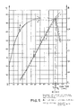
second cylinder 12 and to pass to the drum through saidhollow interspace 13 and saidthird perforations 20. - With regard to fig. 5, the substantial advantageous character of the present invention has been clearly and unequivocally demonstrated experimentally in a number of comparative tests that, in a normal production-line clothes drying machine used to handle a same load of similarly wet clothes through a similarly set drying cycle and, therefore, under fully similar and comparable test conditions, the air temperature when existing from the drum is varied from curve A2 to curve A1, and condensed water is increased from curve B2 to
curve B 1.
Claims (5)
- Clothes drying or combined washing and drying machine comprising a drum (1) provided to hold the clothes to be dried, a conduit (2) adapted to circulate a flow of hot drying air, one or more outlet ports (3) adapted to let the flow of hot drying air circulating through said conduit (2) into said drum (1), a first fan (5) adapted to blow a first flow of drying air through said drum and in said conduit (2), a first heating element (9) provided inside said conduit (2), said conduit (2) for circulating the drying air being further provided with an extension piece (4) that protrudes from the rear wall of the drum into the inner volume thereof in a direction coinciding with the axis of rotation of said drum, characterized in that said extension piece (4) comprises a substantially cylindrical outer wall (10), which is closed at the innermost end portion (11) thereof inside the drum, and a substantially cylindrical inner wall or second cylinder (12) that stretches out longitudinally inside said outer wall (10) and is open at the innermost end portion (14) thereof inside the drum.
- Clothes drying or combined washing and drying machine according to claim 1, characterized in that said innermost end portion (14) of said inner wall (12) is situated at a pre-determined distance (D) from said outer wall (10), so as to enable a flow of drying air to:- flow into and through the hollow interspace (13) defined between said outer wall (10) and said second cylinder (12), and exit through said second cylinder (12),- or the other way round.
- Machine according to claim 2, characterized in that said outer wall (10) is firmly joined with the rear wall of said drum.
- Machine according to claim 2 or 3, characterized in that said second cylinder (12) is firmly joined with the structure of the machine.
- Machine according to any of the claims 2 to 4, characterized in that a part of the flow of drying air is let into said hollow interspace (13) being defined between said outer wall (10) and said second cylinder (12), and is finally blown into said drum through third perforations (20) showed on the rear side of said outer wall (10).
Priority Applications (5)
| Application Number | Priority Date | Filing Date | Title |
|---|---|---|---|
| AT06100344T ATE453009T1 (en) | 2006-01-13 | 2006-01-13 | AIR CIRCULATION DEVICE FOR A HOUSEHOLD CLOTHES DRYER |
| ES06100344T ES2337489T3 (en) | 2006-01-13 | 2006-01-13 | IMPROVEMENTS IN THE AIR CIRCULATION SYSTEM OF A DOMESTIC CLOTHES DRYER. |
| DE602006011265T DE602006011265D1 (en) | 2006-01-13 | 2006-01-13 | Recirculation device for a household tumble dryer |
| EP06100344A EP1808521B1 (en) | 2006-01-13 | 2006-01-13 | Improvement in the air circulation system of a household-type clothes dryer |
| PL06100344T PL1808521T3 (en) | 2006-01-13 | 2006-01-13 | Improvement in the air circulation system of a household-type clothes dryer |
Applications Claiming Priority (1)
| Application Number | Priority Date | Filing Date | Title |
|---|---|---|---|
| EP06100344A EP1808521B1 (en) | 2006-01-13 | 2006-01-13 | Improvement in the air circulation system of a household-type clothes dryer |
Publications (2)
| Publication Number | Publication Date |
|---|---|
| EP1808521A1 true EP1808521A1 (en) | 2007-07-18 |
| EP1808521B1 EP1808521B1 (en) | 2009-12-23 |
Family
ID=36527792
Family Applications (1)
| Application Number | Title | Priority Date | Filing Date |
|---|---|---|---|
| EP06100344A Expired - Lifetime EP1808521B1 (en) | 2006-01-13 | 2006-01-13 | Improvement in the air circulation system of a household-type clothes dryer |
Country Status (5)
| Country | Link |
|---|---|
| EP (1) | EP1808521B1 (en) |
| AT (1) | ATE453009T1 (en) |
| DE (1) | DE602006011265D1 (en) |
| ES (1) | ES2337489T3 (en) |
| PL (1) | PL1808521T3 (en) |
Cited By (2)
| Publication number | Priority date | Publication date | Assignee | Title |
|---|---|---|---|---|
| EP2592184A1 (en) * | 2011-11-08 | 2013-05-15 | Electrolux Home Products Corporation N.V. | Rotary-drum laundry dryer |
| CN111350050A (en) * | 2020-03-26 | 2020-06-30 | 珠海格力电器股份有限公司 | The air duct structure of the washer-drying machine and the washer-drying machine |
Citations (3)
| Publication number | Priority date | Publication date | Assignee | Title |
|---|---|---|---|---|
| BE673173A (en) * | 1965-12-02 | 1966-04-01 | ||
| JPS58221990A (en) * | 1982-06-18 | 1983-12-23 | 株式会社東芝 | Dryer |
| EP1285987A2 (en) * | 2001-08-22 | 2003-02-26 | Lg Electronics Inc. | Clothes dryer |
-
2006
- 2006-01-13 EP EP06100344A patent/EP1808521B1/en not_active Expired - Lifetime
- 2006-01-13 AT AT06100344T patent/ATE453009T1/en not_active IP Right Cessation
- 2006-01-13 ES ES06100344T patent/ES2337489T3/en not_active Expired - Lifetime
- 2006-01-13 DE DE602006011265T patent/DE602006011265D1/en not_active Expired - Lifetime
- 2006-01-13 PL PL06100344T patent/PL1808521T3/en unknown
Patent Citations (3)
| Publication number | Priority date | Publication date | Assignee | Title |
|---|---|---|---|---|
| BE673173A (en) * | 1965-12-02 | 1966-04-01 | ||
| JPS58221990A (en) * | 1982-06-18 | 1983-12-23 | 株式会社東芝 | Dryer |
| EP1285987A2 (en) * | 2001-08-22 | 2003-02-26 | Lg Electronics Inc. | Clothes dryer |
Cited By (2)
| Publication number | Priority date | Publication date | Assignee | Title |
|---|---|---|---|---|
| EP2592184A1 (en) * | 2011-11-08 | 2013-05-15 | Electrolux Home Products Corporation N.V. | Rotary-drum laundry dryer |
| CN111350050A (en) * | 2020-03-26 | 2020-06-30 | 珠海格力电器股份有限公司 | The air duct structure of the washer-drying machine and the washer-drying machine |
Also Published As
| Publication number | Publication date |
|---|---|
| PL1808521T3 (en) | 2010-06-30 |
| ES2337489T3 (en) | 2010-04-26 |
| ATE453009T1 (en) | 2010-01-15 |
| DE602006011265D1 (en) | 2010-02-04 |
| EP1808521B1 (en) | 2009-12-23 |
Similar Documents
| Publication | Publication Date | Title |
|---|---|---|
| US8695228B2 (en) | Composite washing system | |
| CN102782206B (en) | Dryer | |
| US9644310B2 (en) | Household clothes drying machine with clothes disinfection cycle | |
| EP2723928B1 (en) | Laundry washing and drying machine with air-cooled condenser | |
| CN101356311B (en) | Household clothes drying machine with additional condenser | |
| CN102482839B (en) | Clothes Dryers & Washer Dryers | |
| JP2011083459A5 (en) | ||
| EP2636788A1 (en) | Clothes dryer and washer/dryer | |
| EP2592184A1 (en) | Rotary-drum laundry dryer | |
| BRPI0707934A2 (en) | dual fan household clothes dryers | |
| WO2015028231A1 (en) | Rotary-drum laundry dryer | |
| EP1808521B1 (en) | Improvement in the air circulation system of a household-type clothes dryer | |
| JP4243336B2 (en) | Drum type washer / dryer | |
| EP2373841B1 (en) | A laundry dryer | |
| CN102535090B (en) | Laundry dryer and washing and drying machine | |
| JP2005230322A (en) | Clothes dryer | |
| WO2013182403A1 (en) | Laundry dryer with air-cooled condenser | |
| EP3853404B1 (en) | A laundry dryer | |
| KR101167735B1 (en) | Clothes dryer and operating method of the same | |
| KR100999295B1 (en) | Clothes dryer | |
| JP2012223407A (en) | Cloth dryer | |
| WO2005012624A1 (en) | Drying apparatus | |
| JP3907576B2 (en) | Drum type washer / dryer | |
| KR0176895B1 (en) | Apparatus for drying of drum type washing machine | |
| CN116971154B (en) | Roller mechanism, garment care equipment and garment care methods |
Legal Events
| Date | Code | Title | Description |
|---|---|---|---|
| PUAI | Public reference made under article 153(3) epc to a published international application that has entered the european phase |
Free format text: ORIGINAL CODE: 0009012 |
|
| AK | Designated contracting states |
Kind code of ref document: A1 Designated state(s): AT BE BG CH CY CZ DE DK EE ES FI FR GB GR HU IE IS IT LI LT LU LV MC NL PL PT RO SE SI SK TR |
|
| AX | Request for extension of the european patent |
Extension state: AL BA HR MK YU |
|
| 17P | Request for examination filed |
Effective date: 20070827 |
|
| AKX | Designation fees paid |
Designated state(s): AT BE BG CH CY CZ DE DK EE ES FI FR GB GR HU IE IS IT LI LT LU LV MC NL PL PT RO SE SI SK TR |
|
| GRAP | Despatch of communication of intention to grant a patent |
Free format text: ORIGINAL CODE: EPIDOSNIGR1 |
|
| GRAS | Grant fee paid |
Free format text: ORIGINAL CODE: EPIDOSNIGR3 |
|
| GRAA | (expected) grant |
Free format text: ORIGINAL CODE: 0009210 |
|
| AK | Designated contracting states |
Kind code of ref document: B1 Designated state(s): AT BE BG CH CY CZ DE DK EE ES FI FR GB GR HU IE IS IT LI LT LU LV MC NL PL PT RO SE SI SK TR |
|
| REG | Reference to a national code |
Ref country code: GB Ref legal event code: FG4D |
|
| REG | Reference to a national code |
Ref country code: CH Ref legal event code: EP |
|
| REG | Reference to a national code |
Ref country code: IE Ref legal event code: FG4D |
|
| REF | Corresponds to: |
Ref document number: 602006011265 Country of ref document: DE Date of ref document: 20100204 Kind code of ref document: P |
|
| REG | Reference to a national code |
Ref country code: ES Ref legal event code: FG2A Ref document number: 2337489 Country of ref document: ES Kind code of ref document: T3 |
|
| REG | Reference to a national code |
Ref country code: NL Ref legal event code: VDEP Effective date: 20091223 |
|
| PG25 | Lapsed in a contracting state [announced via postgrant information from national office to epo] |
Ref country code: FI Free format text: LAPSE BECAUSE OF FAILURE TO SUBMIT A TRANSLATION OF THE DESCRIPTION OR TO PAY THE FEE WITHIN THE PRESCRIBED TIME-LIMIT Effective date: 20091223 Ref country code: SE Free format text: LAPSE BECAUSE OF FAILURE TO SUBMIT A TRANSLATION OF THE DESCRIPTION OR TO PAY THE FEE WITHIN THE PRESCRIBED TIME-LIMIT Effective date: 20091223 Ref country code: LT Free format text: LAPSE BECAUSE OF FAILURE TO SUBMIT A TRANSLATION OF THE DESCRIPTION OR TO PAY THE FEE WITHIN THE PRESCRIBED TIME-LIMIT Effective date: 20091223 |
|
| LTIE | Lt: invalidation of european patent or patent extension |
Effective date: 20091223 |
|
| PG25 | Lapsed in a contracting state [announced via postgrant information from national office to epo] |
Ref country code: SI Free format text: LAPSE BECAUSE OF FAILURE TO SUBMIT A TRANSLATION OF THE DESCRIPTION OR TO PAY THE FEE WITHIN THE PRESCRIBED TIME-LIMIT Effective date: 20091223 Ref country code: LV Free format text: LAPSE BECAUSE OF FAILURE TO SUBMIT A TRANSLATION OF THE DESCRIPTION OR TO PAY THE FEE WITHIN THE PRESCRIBED TIME-LIMIT Effective date: 20091223 |
|
| PG25 | Lapsed in a contracting state [announced via postgrant information from national office to epo] |
Ref country code: AT Free format text: LAPSE BECAUSE OF FAILURE TO SUBMIT A TRANSLATION OF THE DESCRIPTION OR TO PAY THE FEE WITHIN THE PRESCRIBED TIME-LIMIT Effective date: 20091223 |
|
| PG25 | Lapsed in a contracting state [announced via postgrant information from national office to epo] |
Ref country code: IS Free format text: LAPSE BECAUSE OF FAILURE TO SUBMIT A TRANSLATION OF THE DESCRIPTION OR TO PAY THE FEE WITHIN THE PRESCRIBED TIME-LIMIT Effective date: 20100423 Ref country code: RO Free format text: LAPSE BECAUSE OF FAILURE TO SUBMIT A TRANSLATION OF THE DESCRIPTION OR TO PAY THE FEE WITHIN THE PRESCRIBED TIME-LIMIT Effective date: 20091223 Ref country code: BG Free format text: LAPSE BECAUSE OF FAILURE TO SUBMIT A TRANSLATION OF THE DESCRIPTION OR TO PAY THE FEE WITHIN THE PRESCRIBED TIME-LIMIT Effective date: 20100323 Ref country code: PT Free format text: LAPSE BECAUSE OF FAILURE TO SUBMIT A TRANSLATION OF THE DESCRIPTION OR TO PAY THE FEE WITHIN THE PRESCRIBED TIME-LIMIT Effective date: 20100423 Ref country code: NL Free format text: LAPSE BECAUSE OF FAILURE TO SUBMIT A TRANSLATION OF THE DESCRIPTION OR TO PAY THE FEE WITHIN THE PRESCRIBED TIME-LIMIT Effective date: 20091223 Ref country code: EE Free format text: LAPSE BECAUSE OF FAILURE TO SUBMIT A TRANSLATION OF THE DESCRIPTION OR TO PAY THE FEE WITHIN THE PRESCRIBED TIME-LIMIT Effective date: 20091223 |
|
| PG25 | Lapsed in a contracting state [announced via postgrant information from national office to epo] |
Ref country code: MC Free format text: LAPSE BECAUSE OF NON-PAYMENT OF DUE FEES Effective date: 20100131 Ref country code: SK Free format text: LAPSE BECAUSE OF FAILURE TO SUBMIT A TRANSLATION OF THE DESCRIPTION OR TO PAY THE FEE WITHIN THE PRESCRIBED TIME-LIMIT Effective date: 20091223 Ref country code: CZ Free format text: LAPSE BECAUSE OF FAILURE TO SUBMIT A TRANSLATION OF THE DESCRIPTION OR TO PAY THE FEE WITHIN THE PRESCRIBED TIME-LIMIT Effective date: 20091223 Ref country code: BE Free format text: LAPSE BECAUSE OF FAILURE TO SUBMIT A TRANSLATION OF THE DESCRIPTION OR TO PAY THE FEE WITHIN THE PRESCRIBED TIME-LIMIT Effective date: 20091223 |
|
| REG | Reference to a national code |
Ref country code: CH Ref legal event code: PL |
|
| PG25 | Lapsed in a contracting state [announced via postgrant information from national office to epo] |
Ref country code: LI Free format text: LAPSE BECAUSE OF NON-PAYMENT OF DUE FEES Effective date: 20100131 Ref country code: GR Free format text: LAPSE BECAUSE OF FAILURE TO SUBMIT A TRANSLATION OF THE DESCRIPTION OR TO PAY THE FEE WITHIN THE PRESCRIBED TIME-LIMIT Effective date: 20100324 Ref country code: CY Free format text: LAPSE BECAUSE OF FAILURE TO SUBMIT A TRANSLATION OF THE DESCRIPTION OR TO PAY THE FEE WITHIN THE PRESCRIBED TIME-LIMIT Effective date: 20091223 Ref country code: CH Free format text: LAPSE BECAUSE OF NON-PAYMENT OF DUE FEES Effective date: 20100131 |
|
| PLBE | No opposition filed within time limit |
Free format text: ORIGINAL CODE: 0009261 |
|
| STAA | Information on the status of an ep patent application or granted ep patent |
Free format text: STATUS: NO OPPOSITION FILED WITHIN TIME LIMIT |
|
| 26N | No opposition filed |
Effective date: 20100924 |
|
| PG25 | Lapsed in a contracting state [announced via postgrant information from national office to epo] |
Ref country code: IE Free format text: LAPSE BECAUSE OF NON-PAYMENT OF DUE FEES Effective date: 20100113 Ref country code: DK Free format text: LAPSE BECAUSE OF FAILURE TO SUBMIT A TRANSLATION OF THE DESCRIPTION OR TO PAY THE FEE WITHIN THE PRESCRIBED TIME-LIMIT Effective date: 20091223 |
|
| REG | Reference to a national code |
Ref country code: FR Ref legal event code: CA Effective date: 20120116 |
|
| PGFP | Annual fee paid to national office [announced via postgrant information from national office to epo] |
Ref country code: IT Payment date: 20120123 Year of fee payment: 7 |
|
| PG25 | Lapsed in a contracting state [announced via postgrant information from national office to epo] |
Ref country code: LU Free format text: LAPSE BECAUSE OF NON-PAYMENT OF DUE FEES Effective date: 20100113 Ref country code: HU Free format text: LAPSE BECAUSE OF FAILURE TO SUBMIT A TRANSLATION OF THE DESCRIPTION OR TO PAY THE FEE WITHIN THE PRESCRIBED TIME-LIMIT Effective date: 20100624 |
|
| PG25 | Lapsed in a contracting state [announced via postgrant information from national office to epo] |
Ref country code: TR Free format text: LAPSE BECAUSE OF FAILURE TO SUBMIT A TRANSLATION OF THE DESCRIPTION OR TO PAY THE FEE WITHIN THE PRESCRIBED TIME-LIMIT Effective date: 20091223 |
|
| PGFP | Annual fee paid to national office [announced via postgrant information from national office to epo] |
Ref country code: PL Payment date: 20121224 Year of fee payment: 8 |
|
| PGFP | Annual fee paid to national office [announced via postgrant information from national office to epo] |
Ref country code: ES Payment date: 20130128 Year of fee payment: 8 Ref country code: FR Payment date: 20130213 Year of fee payment: 8 Ref country code: DE Payment date: 20130122 Year of fee payment: 8 Ref country code: GB Payment date: 20130122 Year of fee payment: 8 |
|
| REG | Reference to a national code |
Ref country code: DE Ref legal event code: R119 Ref document number: 602006011265 Country of ref document: DE |
|
| GBPC | Gb: european patent ceased through non-payment of renewal fee |
Effective date: 20140113 |
|
| PG25 | Lapsed in a contracting state [announced via postgrant information from national office to epo] |
Ref country code: DE Free format text: LAPSE BECAUSE OF NON-PAYMENT OF DUE FEES Effective date: 20140801 |
|
| REG | Reference to a national code |
Ref country code: FR Ref legal event code: ST Effective date: 20140930 |
|
| REG | Reference to a national code |
Ref country code: DE Ref legal event code: R119 Ref document number: 602006011265 Country of ref document: DE Effective date: 20140801 |
|
| PG25 | Lapsed in a contracting state [announced via postgrant information from national office to epo] |
Ref country code: FR Free format text: LAPSE BECAUSE OF NON-PAYMENT OF DUE FEES Effective date: 20140131 Ref country code: GB Free format text: LAPSE BECAUSE OF NON-PAYMENT OF DUE FEES Effective date: 20140113 |
|
| REG | Reference to a national code |
Ref country code: PL Ref legal event code: LAPE |
|
| PG25 | Lapsed in a contracting state [announced via postgrant information from national office to epo] |
Ref country code: PL Free format text: LAPSE BECAUSE OF NON-PAYMENT OF DUE FEES Effective date: 20140113 |
|
| REG | Reference to a national code |
Ref country code: ES Ref legal event code: FD2A Effective date: 20150731 |
|
| PG25 | Lapsed in a contracting state [announced via postgrant information from national office to epo] |
Ref country code: ES Free format text: LAPSE BECAUSE OF NON-PAYMENT OF DUE FEES Effective date: 20140114 |
|
| PG25 | Lapsed in a contracting state [announced via postgrant information from national office to epo] |
Ref country code: IT Free format text: LAPSE BECAUSE OF NON-PAYMENT OF DUE FEES Effective date: 20140113 |