EP3853404B1 - A laundry dryer - Google Patents
A laundry dryer Download PDFInfo
- Publication number
- EP3853404B1 EP3853404B1 EP19748818.2A EP19748818A EP3853404B1 EP 3853404 B1 EP3853404 B1 EP 3853404B1 EP 19748818 A EP19748818 A EP 19748818A EP 3853404 B1 EP3853404 B1 EP 3853404B1
- Authority
- EP
- European Patent Office
- Prior art keywords
- fan
- drum
- air
- laundry
- circulation duct
- Prior art date
- Legal status (The legal status is an assumption and is not a legal conclusion. Google has not performed a legal analysis and makes no representation as to the accuracy of the status listed.)
- Active
Links
Images
Classifications
-
- D—TEXTILES; PAPER
- D06—TREATMENT OF TEXTILES OR THE LIKE; LAUNDERING; FLEXIBLE MATERIALS NOT OTHERWISE PROVIDED FOR
- D06F—LAUNDERING, DRYING, IRONING, PRESSING OR FOLDING TEXTILE ARTICLES
- D06F58/00—Domestic laundry dryers
- D06F58/20—General details of domestic laundry dryers
-
- D—TEXTILES; PAPER
- D06—TREATMENT OF TEXTILES OR THE LIKE; LAUNDERING; FLEXIBLE MATERIALS NOT OTHERWISE PROVIDED FOR
- D06F—LAUNDERING, DRYING, IRONING, PRESSING OR FOLDING TEXTILE ARTICLES
- D06F58/00—Domestic laundry dryers
- D06F58/02—Domestic laundry dryers having dryer drums rotating about a horizontal axis
-
- D—TEXTILES; PAPER
- D06—TREATMENT OF TEXTILES OR THE LIKE; LAUNDERING; FLEXIBLE MATERIALS NOT OTHERWISE PROVIDED FOR
- D06F—LAUNDERING, DRYING, IRONING, PRESSING OR FOLDING TEXTILE ARTICLES
- D06F58/00—Domestic laundry dryers
- D06F58/20—General details of domestic laundry dryers
- D06F58/206—Heat pump arrangements
Definitions
- the present invention relates to a heat pump or conventional laundry dryer.
- the drying air moved by a fan is passed over the laundry inside the drum to be dehumidified and the water vapor in the air is condensed in the condenser.
- the drying air dehumidified in the condenser is then heated by being passed over the heater, and thus hot and dry air is delivered onto the laundry.
- the heat pump used for drying the laundry is composed of flow pipes wherein the refrigerant fluid flows, a compressor which provides the circulation of the refrigerant by pressurizing the same, an evaporator and a condenser. In the drying process, the drying air moved by the process fan is passed over the laundry.
- the condenser located in the heat pump functions as a heater and the evaporator as a condenser.
- the drying air is heated while passing over the condenser, delivered onto the laundry as heated and after dehumidifying the laundry, is condensed while passing over the evaporator.
- a single motor is used for moving the drum and operating the fan which provides the air circulation.
- the drum rotates clockwise or counterclockwise depending on the direction of the motor, and since the process fan is driven by the same motor, the process fan similarly rotates in both directions and provides air flow.
- the drum Since in laundry dryers the fan, which provides the air circulation, and the drum are driven by the same motor, the drum also has to rotate continuously while providing air flow. This causes the noise to increase and the delicate laundry to be worn down due to the mechanical effect caused by the rotation of the drum.
- the aim of the present invention is the realization of a laundry dryer wherein the delicate laundry is prevented from being worn down and the drying process duration is shortened.
- EP2765235 discloses a laundry dryer comprising a control unit.
- German Patent Application No. DE2429078 discloses an automatic clothes drier comprises a horizontal-axis rotary perforated drum surrounded at a distance by a stationary casing, and a condenser for removing humidity from the drying air.
- the laundry dryer realized in order to attain the aim of the present invention comprises a heat pump system composed of an air circulation duct which enables the process air to be passed over the laundry in the drum, a first fan which moves the process air, a compressor which provides the circulation of the refrigerant, an evaporator and a condenser, or in the conventional type, a heater and a heat exchanger.
- a main motor operates the drum and the first fan together.
- the process air is continued to be circulated when the drum and the first fan are deactivated.
- the second fan is positioned at the outlet of the condenser in the heat pump laundry dryer, and at the outlet of the heater in the conventional laundry dryer.
- the laundry dryer (1) comprises a body; a drum (2) wherein the laundry to be dried is placed; a heat pump system having an air circulation duct (3) which enables the process air to be passed over the laundry in the drum (2), a first fan (4) which is disposed in the air circulation duct (3) and which moves the process air, a compressor (5) which performs the refrigerant cycle, an evaporator (6) which enables the process air to be dehumidified and a condenser (7) which enables the process air to be heated; a main motor (8) which operates the drum (2) and the first fan (4) at the same time, thus rotating the drum (2) during the drying process while providing the circulation of the process air by means of the first fan (4); and a control unit (11) which regulates the drying process.
- the laundry dryer (1) of the present invention comprises a second fan (10) which is disposed in the air circulation duct (3), which provides the continuity of the circulation of the process air in the drum (2) via the air circulation duct (3) when the drum (2) and the first fan (4) are deactivated during the drying process, and which is operated by an auxiliary motor (9) independently of the main motor (8).
- the second fan (10) is positioned in the air circulation duct (3) at the outlet of the condenser (7) where the humidity of the process air is at the lowest level and the temperature of the process air is at the highest level. Moreover, the outlet of the condenser (7) is the point which least affects the flow rate of the process air. Thus, the adverse effect on the energy efficiency of the system when the second fan (10) is deactivated is minimized.
- the humid process air leaving the drum (2) passes through the evaporator (6) and the condenser (7) and then is directed to the drum (2) via the air circulation duct (3) by the first fan (4).
- the drum (2) and the fan (4) which enables the process air to be circulated in the air circulation duct (3) and the drum (2) are driven by the main motor (8). Therefore, when the drum (2) stops the first fan (4) also stops, and when the drum (2) rotates in the opposite direction, the first fan (4) also rates in the opposite direction. Particularly in delicate textile programs and quiet drying programs, the drum (2) is required to be stopped at intervals in order to reduce the movement thereof.
- the second fan (10) when the drum (2) and the first fan (4) are stopped, the second fan (10) is activated by the auxiliary fan (9), thus resuming the process air flow.
- the second fan (10) moves the air with high temperature and low humidity at the outlet of the condenser (7), thus improving the drying performance.
- the delicate laundry is prevented from being worn down and is enabled to be quickly dried.
- control unit (11) executes a drying program wherein the second fan (10) is operated only when the drum (2) and the first fan (4) are stopped intermittently. Said drying program is used to prevent the laundry affected by the mechanical movement from being worn down and/or to consume less energy.
- control unit (11) executes a drying program wherein the second fan (10) is continuously operated and the drum (2) and the first fan (4) are stopped intermittently. Said drying program is used to air the laundry and remove odors and to decrease the formation of lint and the mechanical damage caused by the continuous rotation of the dry laundry with the drum (2).
- control unit (11) executes a drying program wherein the second fan (10) is continuously operated and the drum (2) and the first fan (4) are completely stopped.
- this program the air at high temperature and low flow rate is enabled to flow, and delicate laundry, which is excessively affected by the mechanical movement, is prevented from being worn down.
- hygiene programs only the second fan (10) is operated, thus performing the drying process at low flow rate.
- control unit (11) executes a drying program wherein the drum (2), the first fan (4) and the second fan (10) are continuously operated.
- This drying program is used to decrease the total drying time by increasing the flow rate of the process air and to quickly air the laundry and remove odors.
- a conventional laundry dryer (12) comprises a drum (2) wherein the laundry to be dried is placed; an air circulation duct (3) which enables the process air to be passed over the laundry in the drum (2); a first fan (4) which is disposed in the air circulation duct (3) and which moves the process air; a heater (13) which heats the process air; a heat exchanger (14) which dehumidifies the process air; a main motor (8) which operates the drum (2) and the first fan (4) at the same time, thus rotating the drum (2) during the drying process while providing the circulation of the process air by means of the first fan (4); and a second fan (10) which is disposed in the air circulation duct (3), which is operated by an auxiliary motor (9) independently of the main motor (8), and which provides the continuity of the circulation of the process air in the drum (2) via the air circulation duct (3) when the drum (2) and the first fan (4) are deactivated.
- the second fan (10) is disposed in the air circulation duct (3) at the outlet of the heater (13).
- the second fan (10) which is disposed in the air circulation duct (3) at the outlet of the condenser (7) enables the drying process to be carried out with minimum mechanical effect while not moving or barely moving the drum (2) during the drying of the delicate laundry.
- the laundry is prevented from being worn down. Energy consumption, total drying time and noises caused by the rotation of the drum (2) are decreased.
Landscapes
- Engineering & Computer Science (AREA)
- Textile Engineering (AREA)
- Detail Structures Of Washing Machines And Dryers (AREA)
Description
- The present invention relates to a heat pump or conventional laundry dryer.
- In conventional laundry dryers wherein the drying air is circulated through a closed cycle, the drying air moved by a fan is passed over the laundry inside the drum to be dehumidified and the water vapor in the air is condensed in the condenser. The drying air dehumidified in the condenser is then heated by being passed over the heater, and thus hot and dry air is delivered onto the laundry. In heat pump laundry dryers, the heat pump used for drying the laundry is composed of flow pipes wherein the refrigerant fluid flows, a compressor which provides the circulation of the refrigerant by pressurizing the same, an evaporator and a condenser. In the drying process, the drying air moved by the process fan is passed over the laundry. The condenser located in the heat pump functions as a heater and the evaporator as a condenser. The drying air is heated while passing over the condenser, delivered onto the laundry as heated and after dehumidifying the laundry, is condensed while passing over the evaporator.
- In conventional and heat pump laundry dryers, a single motor is used for moving the drum and operating the fan which provides the air circulation. In this case during the operation of the motor the drum rotates clockwise or counterclockwise depending on the direction of the motor, and since the process fan is driven by the same motor, the process fan similarly rotates in both directions and provides air flow.
- In heat pump or conventional laundry dryers, sufficient air flow is required for the systems, which perform the heating and dehumidification processes, to operate so as to carry out the drying process. In case of insufficient air flow, the heater in conventional laundry dryers and the compressor in heat pump laundry dryers are turned off and deactivated for security reasons, which in turn prolongs the drying process.
- Since in laundry dryers the fan, which provides the air circulation, and the drum are driven by the same motor, the drum also has to rotate continuously while providing air flow. This causes the noise to increase and the delicate laundry to be worn down due to the mechanical effect caused by the rotation of the drum.
- In the Patent Application No.
US2017254014 (A1 ), in a laundry dryer two fans, one at the inlet of the drum and one at the outlet thereof, are provided so as to increase the flow rate of the air. - The aim of the present invention is the realization of a laundry dryer wherein the delicate laundry is prevented from being worn down and the drying process duration is shortened.
- In the state of the art, European Patent Application No.
EP2765235 discloses a laundry dryer comprising a control unit. - In the state of the art, German Patent Application No.
DE2429078 discloses an automatic clothes drier comprises a horizontal-axis rotary perforated drum surrounded at a distance by a stationary casing, and a condenser for removing humidity from the drying air. - The above stated problem is solved by a laundry dryer as defined in
claim 1 and by a conventional laundry dryer as defined inclaim 7. - Preferred embodiments are defined in the dependent claims respectively.
- The laundry dryer realized in order to attain the aim of the present invention comprises a heat pump system composed of an air circulation duct which enables the process air to be passed over the laundry in the drum, a first fan which moves the process air, a compressor which provides the circulation of the refrigerant, an evaporator and a condenser, or in the conventional type, a heater and a heat exchanger. In both types of laundry dryers, a main motor operates the drum and the first fan together. In the embodiment of the present invention, by means of a second fan disposed in the air circulation duct, the process air is continued to be circulated when the drum and the first fan are deactivated. The second fan is positioned at the outlet of the condenser in the heat pump laundry dryer, and at the outlet of the heater in the conventional laundry dryer.
- The laundry dryer realized in order to attain the aim of the present invention is illustrated in the attached figures, where:
-
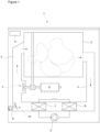
Figure 1 - is the schematic view of a heat pump laundry dryer. -
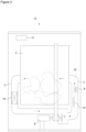
Figure 2 - is the schematic view of a conventional laundry dryer. - The elements illustrated in the figures are numbered as follows:
- 1.
- Laundry dryer
- 2.
- Drum
- 3.
- Air circulation duct
- 4.
- First fan
- 5.
- Compressor
- 6.
- Evaporator
- 7.
- Condenser
- 8.
- Main motor
- 9.
- Auxiliary motor
- 10.
- Second fan
- 11.
- Control unit
- 12.
- Conventional laundry dryer
- 13.
- Heater
- 14.
- Heat exchanger
- The laundry dryer (1) comprises a body; a drum (2) wherein the laundry to be dried is placed; a heat pump system having an air circulation duct (3) which enables the process air to be passed over the laundry in the drum (2), a first fan (4) which is disposed in the air circulation duct (3) and which moves the process air, a compressor (5) which performs the refrigerant cycle, an evaporator (6) which enables the process air to be dehumidified and a condenser (7) which enables the process air to be heated; a main motor (8) which operates the drum (2) and the first fan (4) at the same time, thus rotating the drum (2) during the drying process while providing the circulation of the process air by means of the first fan (4); and a control unit (11) which regulates the drying process.
- The laundry dryer (1) of the present invention comprises a second fan (10) which is disposed in the air circulation duct (3), which provides the continuity of the circulation of the process air in the drum (2) via the air circulation duct (3) when the drum (2) and the first fan (4) are deactivated during the drying process, and which is operated by an auxiliary motor (9) independently of the main motor (8).
- In an embodiment of the present invention, the second fan (10) is positioned in the air circulation duct (3) at the outlet of the condenser (7) where the humidity of the process air is at the lowest level and the temperature of the process air is at the highest level. Moreover, the outlet of the condenser (7) is the point which least affects the flow rate of the process air. Thus, the adverse effect on the energy efficiency of the system when the second fan (10) is deactivated is minimized.
- In the laundry dryer (1), the humid process air leaving the drum (2) passes through the evaporator (6) and the condenser (7) and then is directed to the drum (2) via the air circulation duct (3) by the first fan (4). The drum (2) and the fan (4) which enables the process air to be circulated in the air circulation duct (3) and the drum (2) are driven by the main motor (8). Therefore, when the drum (2) stops the first fan (4) also stops, and when the drum (2) rotates in the opposite direction, the first fan (4) also rates in the opposite direction. Particularly in delicate textile programs and quiet drying programs, the drum (2) is required to be stopped at intervals in order to reduce the movement thereof. In the embodiment of the present invention, when the drum (2) and the first fan (4) are stopped, the second fan (10) is activated by the auxiliary fan (9), thus resuming the process air flow. The second fan (10) moves the air with high temperature and low humidity at the outlet of the condenser (7), thus improving the drying performance. The delicate laundry is prevented from being worn down and is enabled to be quickly dried.
- In an embodiment of the present invention, the control unit (11) executes a drying program wherein the second fan (10) is operated only when the drum (2) and the first fan (4) are stopped intermittently. Said drying program is used to prevent the laundry affected by the mechanical movement from being worn down and/or to consume less energy.
- In an embodiment of the present invention, the control unit (11) executes a drying program wherein the second fan (10) is continuously operated and the drum (2) and the first fan (4) are stopped intermittently. Said drying program is used to air the laundry and remove odors and to decrease the formation of lint and the mechanical damage caused by the continuous rotation of the dry laundry with the drum (2).
- In an embodiment of the present invention, the control unit (11) executes a drying program wherein the second fan (10) is continuously operated and the drum (2) and the first fan (4) are completely stopped. In this program, the air at high temperature and low flow rate is enabled to flow, and delicate laundry, which is excessively affected by the mechanical movement, is prevented from being worn down. In hygiene programs, only the second fan (10) is operated, thus performing the drying process at low flow rate.
- In an embodiment of the present invention, the control unit (11) executes a drying program wherein the drum (2), the first fan (4) and the second fan (10) are continuously operated. This drying program is used to decrease the total drying time by increasing the flow rate of the process air and to quickly air the laundry and remove odors.
- In another embodiment of the present invention, a conventional laundry dryer (12) comprises a drum (2) wherein the laundry to be dried is placed; an air circulation duct (3) which enables the process air to be passed over the laundry in the drum (2); a first fan (4) which is disposed in the air circulation duct (3) and which moves the process air; a heater (13) which heats the process air; a heat exchanger (14) which dehumidifies the process air; a main motor (8) which operates the drum (2) and the first fan (4) at the same time, thus rotating the drum (2) during the drying process while providing the circulation of the process air by means of the first fan (4); and a second fan (10) which is disposed in the air circulation duct (3), which is operated by an auxiliary motor (9) independently of the main motor (8), and which provides the continuity of the circulation of the process air in the drum (2) via the air circulation duct (3) when the drum (2) and the first fan (4) are deactivated.
- In the conventional laundry dryer (12), the second fan (10) is disposed in the air circulation duct (3) at the outlet of the heater (13).
- In the laundry dryer (1) of the present invention, the second fan (10) which is disposed in the air circulation duct (3) at the outlet of the condenser (7) enables the drying process to be carried out with minimum mechanical effect while not moving or barely moving the drum (2) during the drying of the delicate laundry. Thus, the laundry is prevented from being worn down. Energy consumption, total drying time and noises caused by the rotation of the drum (2) are decreased.
Claims (8)
- A laundry dryer (1) comprising a drum (2) wherein the laundry to be dried is placed, an air circulation duct (3) which enables the process air to be passed over the laundry in the drum (2), a first fan (4) which is disposed in the air circulation duct (3) and which moves the process air, a compressor (5) which performs the refrigerant cycle, an evaporator (6), a condenser (7), a main motor (8) which operates the drum (2) and the first fan (4), and a control unit (11),- characterized by a second fan (10) which is disposed in the air circulation duct (3), which provides the continuity of the circulation of the process air in the drum (2) via the air circulation duct (3) when the drum (2) and the first fan (4) are deactivated during the drying process, and which is operated by an auxiliary motor (9) independently of the main motor (8).
- A laundry dryer (1) as in Claim 1, characterized by the second fan (10) which is disposed in the air circulation duct (3) at the outlet of the condenser (7).
- A laundry dryer (1) as in Claim 1 or 2, characterized by the control unit (11) which executes a drying program wherein the second fan (10) is operated only when the drum (2) and the first fan (4) are stopped intermittently.
- A laundry dryer (1) as in Claim 1 or 2, characterized by the control unit (11) which executes a drying program wherein the second fan (10) is continuously operated and the drum (2) and the first fan (4) are stopped intermittently.
- A laundry dryer (1) as in Claim 1 or 2, characterized by the control unit (11) which executes a drying program wherein the second fan (10) is continuously operated and the drum (2) and the first fan (4) are completely stopped.
- A laundry dryer (1) as in Claim 1 or 2, characterized by the control unit (11) which executes a drying program wherein the drum (2), the first fan (4) and the second fan (10) are continuously operated.
- A conventional laundry dryer (1) comprising a drum (2), an air circulation duct (3), a first fan (4), a main motor (8) which operates the drum (2) and the first fan (4) at the same time, a heater (13) which heats the process air, a heat exchanger (14) which dehumidifies the process air, characterized by a second fan (10) which is disposed in the air circulation duct (3), which provides the continuity of the circulation of the process air in the drum (2) via the air circulation duct (3) when the drum (2) and the first fan (4) are deactivated and which is operated by an auxiliary motor (9) independently of the main motor (8).
- A conventional laundry dryer (12) as in Claim 7, characterized by the second fan (10) which is disposed in the air circulation duct (3) at the outlet of the heater (13).
Applications Claiming Priority (2)
| Application Number | Priority Date | Filing Date | Title |
|---|---|---|---|
| TR201813389 | 2018-09-18 | ||
| PCT/EP2019/070682 WO2020057839A1 (en) | 2018-09-18 | 2019-07-31 | A laundry dryer |
Publications (2)
| Publication Number | Publication Date |
|---|---|
| EP3853404A1 EP3853404A1 (en) | 2021-07-28 |
| EP3853404B1 true EP3853404B1 (en) | 2024-01-03 |
Family
ID=67514652
Family Applications (1)
| Application Number | Title | Priority Date | Filing Date |
|---|---|---|---|
| EP19748818.2A Active EP3853404B1 (en) | 2018-09-18 | 2019-07-31 | A laundry dryer |
Country Status (3)
| Country | Link |
|---|---|
| EP (1) | EP3853404B1 (en) |
| PL (1) | PL3853404T3 (en) |
| WO (1) | WO2020057839A1 (en) |
Families Citing this family (1)
| Publication number | Priority date | Publication date | Assignee | Title |
|---|---|---|---|---|
| CN116657388A (en) * | 2022-02-17 | 2023-08-29 | 青岛海尔洗衣机有限公司 | Control method of clothes care machine |
Family Cites Families (4)
| Publication number | Priority date | Publication date | Assignee | Title |
|---|---|---|---|---|
| DE2429078A1 (en) * | 1974-03-20 | 1976-01-08 | Hugo Werner Geschka | Clothes drier with horizontal-axis rotary perforated drum - preventing air from circulating around drum, without causing creases |
| JP2014150859A (en) * | 2013-02-06 | 2014-08-25 | Panasonic Corp | Clothes dryer |
| GB2519185B (en) * | 2014-05-30 | 2015-09-30 | Dbk David & Baader Gmbh | A tumble dryer |
| US20170254014A1 (en) | 2016-03-07 | 2017-09-07 | Atul Vir | Venting laundry dryer with two fans |
-
2019
- 2019-07-31 WO PCT/EP2019/070682 patent/WO2020057839A1/en not_active Ceased
- 2019-07-31 PL PL19748818.2T patent/PL3853404T3/en unknown
- 2019-07-31 EP EP19748818.2A patent/EP3853404B1/en active Active
Also Published As
| Publication number | Publication date |
|---|---|
| PL3853404T3 (en) | 2024-05-20 |
| EP3853404A1 (en) | 2021-07-28 |
| WO2020057839A1 (en) | 2020-03-26 |
Similar Documents
| Publication | Publication Date | Title |
|---|---|---|
| EP2723928B1 (en) | Laundry washing and drying machine with air-cooled condenser | |
| KR101718042B1 (en) | Clothes dryer | |
| EP2789728B1 (en) | Method for controlling a motor of a laundry dryer | |
| JP2014150859A (en) | Clothes dryer | |
| JP6889521B2 (en) | Clothes dryer | |
| EP2576889B1 (en) | Energy saving thermoelectric heat pump laundry dryer | |
| JP6752568B2 (en) | Clothes dryer | |
| JPH01212599A (en) | Washer-dryer | |
| JP4384203B2 (en) | Clothes dryer | |
| EP3853404B1 (en) | A laundry dryer | |
| WO2016107699A1 (en) | A laundry washing and/or drying machine comprising an air-cooled condenser | |
| JP2009066113A (en) | Clothes dryer | |
| JP6207919B2 (en) | Drum type washer / dryer | |
| JP2011120746A (en) | Clothes dryer | |
| KR101253150B1 (en) | clothes drier and controlling methode for the same | |
| JP6710858B2 (en) | Drum type washer/dryer and method for drying clothes | |
| JP6466093B2 (en) | Clothes dryer | |
| WO2013182401A1 (en) | Laundry dryer with air-cooled condenser | |
| US20170254014A1 (en) | Venting laundry dryer with two fans | |
| JP7633125B2 (en) | Clothes dryer | |
| CN101135101B (en) | Washing machine having socketed dehumidifier as washing machine drying apparatus | |
| CN112030497A (en) | Heat pump clothes dryer and control method thereof | |
| KR101167735B1 (en) | Clothes dryer and operating method of the same | |
| WO2011151213A2 (en) | A thermoelectric heat pump laundry dryer wherein energy is saved | |
| JP2011182861A (en) | Clothes dryer |
Legal Events
| Date | Code | Title | Description |
|---|---|---|---|
| STAA | Information on the status of an ep patent application or granted ep patent |
Free format text: STATUS: UNKNOWN |
|
| STAA | Information on the status of an ep patent application or granted ep patent |
Free format text: STATUS: THE INTERNATIONAL PUBLICATION HAS BEEN MADE |
|
| PUAI | Public reference made under article 153(3) epc to a published international application that has entered the european phase |
Free format text: ORIGINAL CODE: 0009012 |
|
| STAA | Information on the status of an ep patent application or granted ep patent |
Free format text: STATUS: REQUEST FOR EXAMINATION WAS MADE |
|
| 17P | Request for examination filed |
Effective date: 20210224 |
|
| AK | Designated contracting states |
Kind code of ref document: A1 Designated state(s): AL AT BE BG CH CY CZ DE DK EE ES FI FR GB GR HR HU IE IS IT LI LT LU LV MC MK MT NL NO PL PT RO RS SE SI SK SM TR |
|
| DAV | Request for validation of the european patent (deleted) | ||
| DAX | Request for extension of the european patent (deleted) | ||
| GRAP | Despatch of communication of intention to grant a patent |
Free format text: ORIGINAL CODE: EPIDOSNIGR1 |
|
| STAA | Information on the status of an ep patent application or granted ep patent |
Free format text: STATUS: GRANT OF PATENT IS INTENDED |
|
| INTG | Intention to grant announced |
Effective date: 20230907 |
|
| GRAS | Grant fee paid |
Free format text: ORIGINAL CODE: EPIDOSNIGR3 |
|
| GRAA | (expected) grant |
Free format text: ORIGINAL CODE: 0009210 |
|
| STAA | Information on the status of an ep patent application or granted ep patent |
Free format text: STATUS: THE PATENT HAS BEEN GRANTED |
|
| AK | Designated contracting states |
Kind code of ref document: B1 Designated state(s): AL AT BE BG CH CY CZ DE DK EE ES FI FR GB GR HR HU IE IS IT LI LT LU LV MC MK MT NL NO PL PT RO RS SE SI SK SM TR |
|
| REG | Reference to a national code |
Ref country code: GB Ref legal event code: FG4D |
|
| REG | Reference to a national code |
Ref country code: CH Ref legal event code: EP |
|
| REG | Reference to a national code |
Ref country code: DE Ref legal event code: R096 Ref document number: 602019044455 Country of ref document: DE |
|
| REG | Reference to a national code |
Ref country code: IE Ref legal event code: FG4D |
|
| REG | Reference to a national code |
Ref country code: LT Ref legal event code: MG9D |
|
| PG25 | Lapsed in a contracting state [announced via postgrant information from national office to epo] |
Ref country code: ES Free format text: LAPSE BECAUSE OF FAILURE TO SUBMIT A TRANSLATION OF THE DESCRIPTION OR TO PAY THE FEE WITHIN THE PRESCRIBED TIME-LIMIT Effective date: 20240103 |
|
| PG25 | Lapsed in a contracting state [announced via postgrant information from national office to epo] |
Ref country code: ES Free format text: LAPSE BECAUSE OF FAILURE TO SUBMIT A TRANSLATION OF THE DESCRIPTION OR TO PAY THE FEE WITHIN THE PRESCRIBED TIME-LIMIT Effective date: 20240103 |
|
| REG | Reference to a national code |
Ref country code: NL Ref legal event code: MP Effective date: 20240103 |
|
| REG | Reference to a national code |
Ref country code: AT Ref legal event code: MK05 Ref document number: 1646879 Country of ref document: AT Kind code of ref document: T Effective date: 20240103 |
|
| PG25 | Lapsed in a contracting state [announced via postgrant information from national office to epo] |
Ref country code: NL Free format text: LAPSE BECAUSE OF FAILURE TO SUBMIT A TRANSLATION OF THE DESCRIPTION OR TO PAY THE FEE WITHIN THE PRESCRIBED TIME-LIMIT Effective date: 20240103 |
|
| PG25 | Lapsed in a contracting state [announced via postgrant information from national office to epo] |
Ref country code: NL Free format text: LAPSE BECAUSE OF FAILURE TO SUBMIT A TRANSLATION OF THE DESCRIPTION OR TO PAY THE FEE WITHIN THE PRESCRIBED TIME-LIMIT Effective date: 20240103 |
|
| PG25 | Lapsed in a contracting state [announced via postgrant information from national office to epo] |
Ref country code: IS Free format text: LAPSE BECAUSE OF FAILURE TO SUBMIT A TRANSLATION OF THE DESCRIPTION OR TO PAY THE FEE WITHIN THE PRESCRIBED TIME-LIMIT Effective date: 20240503 |
|
| PG25 | Lapsed in a contracting state [announced via postgrant information from national office to epo] |
Ref country code: LT Free format text: LAPSE BECAUSE OF FAILURE TO SUBMIT A TRANSLATION OF THE DESCRIPTION OR TO PAY THE FEE WITHIN THE PRESCRIBED TIME-LIMIT Effective date: 20240103 |
|
| PG25 | Lapsed in a contracting state [announced via postgrant information from national office to epo] |
Ref country code: GR Free format text: LAPSE BECAUSE OF FAILURE TO SUBMIT A TRANSLATION OF THE DESCRIPTION OR TO PAY THE FEE WITHIN THE PRESCRIBED TIME-LIMIT Effective date: 20240404 |
|
| PG25 | Lapsed in a contracting state [announced via postgrant information from national office to epo] |
Ref country code: HR Free format text: LAPSE BECAUSE OF FAILURE TO SUBMIT A TRANSLATION OF THE DESCRIPTION OR TO PAY THE FEE WITHIN THE PRESCRIBED TIME-LIMIT Effective date: 20240103 Ref country code: RS Free format text: LAPSE BECAUSE OF FAILURE TO SUBMIT A TRANSLATION OF THE DESCRIPTION OR TO PAY THE FEE WITHIN THE PRESCRIBED TIME-LIMIT Effective date: 20240403 |
|
| PG25 | Lapsed in a contracting state [announced via postgrant information from national office to epo] |
Ref country code: CZ Free format text: LAPSE BECAUSE OF FAILURE TO SUBMIT A TRANSLATION OF THE DESCRIPTION OR TO PAY THE FEE WITHIN THE PRESCRIBED TIME-LIMIT Effective date: 20240103 Ref country code: AT Free format text: LAPSE BECAUSE OF FAILURE TO SUBMIT A TRANSLATION OF THE DESCRIPTION OR TO PAY THE FEE WITHIN THE PRESCRIBED TIME-LIMIT Effective date: 20240103 |
|
| PG25 | Lapsed in a contracting state [announced via postgrant information from national office to epo] |
Ref country code: RS Free format text: LAPSE BECAUSE OF FAILURE TO SUBMIT A TRANSLATION OF THE DESCRIPTION OR TO PAY THE FEE WITHIN THE PRESCRIBED TIME-LIMIT Effective date: 20240403 Ref country code: NO Free format text: LAPSE BECAUSE OF FAILURE TO SUBMIT A TRANSLATION OF THE DESCRIPTION OR TO PAY THE FEE WITHIN THE PRESCRIBED TIME-LIMIT Effective date: 20240403 Ref country code: LT Free format text: LAPSE BECAUSE OF FAILURE TO SUBMIT A TRANSLATION OF THE DESCRIPTION OR TO PAY THE FEE WITHIN THE PRESCRIBED TIME-LIMIT Effective date: 20240103 Ref country code: IS Free format text: LAPSE BECAUSE OF FAILURE TO SUBMIT A TRANSLATION OF THE DESCRIPTION OR TO PAY THE FEE WITHIN THE PRESCRIBED TIME-LIMIT Effective date: 20240503 Ref country code: HR Free format text: LAPSE BECAUSE OF FAILURE TO SUBMIT A TRANSLATION OF THE DESCRIPTION OR TO PAY THE FEE WITHIN THE PRESCRIBED TIME-LIMIT Effective date: 20240103 Ref country code: GR Free format text: LAPSE BECAUSE OF FAILURE TO SUBMIT A TRANSLATION OF THE DESCRIPTION OR TO PAY THE FEE WITHIN THE PRESCRIBED TIME-LIMIT Effective date: 20240404 Ref country code: CZ Free format text: LAPSE BECAUSE OF FAILURE TO SUBMIT A TRANSLATION OF THE DESCRIPTION OR TO PAY THE FEE WITHIN THE PRESCRIBED TIME-LIMIT Effective date: 20240103 Ref country code: BG Free format text: LAPSE BECAUSE OF FAILURE TO SUBMIT A TRANSLATION OF THE DESCRIPTION OR TO PAY THE FEE WITHIN THE PRESCRIBED TIME-LIMIT Effective date: 20240103 Ref country code: AT Free format text: LAPSE BECAUSE OF FAILURE TO SUBMIT A TRANSLATION OF THE DESCRIPTION OR TO PAY THE FEE WITHIN THE PRESCRIBED TIME-LIMIT Effective date: 20240103 |
|
| PG25 | Lapsed in a contracting state [announced via postgrant information from national office to epo] |
Ref country code: PT Free format text: LAPSE BECAUSE OF FAILURE TO SUBMIT A TRANSLATION OF THE DESCRIPTION OR TO PAY THE FEE WITHIN THE PRESCRIBED TIME-LIMIT Effective date: 20240503 |
|
| PG25 | Lapsed in a contracting state [announced via postgrant information from national office to epo] |
Ref country code: SE Free format text: LAPSE BECAUSE OF FAILURE TO SUBMIT A TRANSLATION OF THE DESCRIPTION OR TO PAY THE FEE WITHIN THE PRESCRIBED TIME-LIMIT Effective date: 20240103 Ref country code: PT Free format text: LAPSE BECAUSE OF FAILURE TO SUBMIT A TRANSLATION OF THE DESCRIPTION OR TO PAY THE FEE WITHIN THE PRESCRIBED TIME-LIMIT Effective date: 20240503 Ref country code: LV Free format text: LAPSE BECAUSE OF FAILURE TO SUBMIT A TRANSLATION OF THE DESCRIPTION OR TO PAY THE FEE WITHIN THE PRESCRIBED TIME-LIMIT Effective date: 20240103 |
|
| REG | Reference to a national code |
Ref country code: DE Ref legal event code: R097 Ref document number: 602019044455 Country of ref document: DE |
|
| PG25 | Lapsed in a contracting state [announced via postgrant information from national office to epo] |
Ref country code: DK Free format text: LAPSE BECAUSE OF FAILURE TO SUBMIT A TRANSLATION OF THE DESCRIPTION OR TO PAY THE FEE WITHIN THE PRESCRIBED TIME-LIMIT Effective date: 20240103 |
|
| PG25 | Lapsed in a contracting state [announced via postgrant information from national office to epo] |
Ref country code: SM Free format text: LAPSE BECAUSE OF FAILURE TO SUBMIT A TRANSLATION OF THE DESCRIPTION OR TO PAY THE FEE WITHIN THE PRESCRIBED TIME-LIMIT Effective date: 20240103 |
|
| PG25 | Lapsed in a contracting state [announced via postgrant information from national office to epo] |
Ref country code: EE Free format text: LAPSE BECAUSE OF FAILURE TO SUBMIT A TRANSLATION OF THE DESCRIPTION OR TO PAY THE FEE WITHIN THE PRESCRIBED TIME-LIMIT Effective date: 20240103 |
|
| PG25 | Lapsed in a contracting state [announced via postgrant information from national office to epo] |
Ref country code: SK Free format text: LAPSE BECAUSE OF FAILURE TO SUBMIT A TRANSLATION OF THE DESCRIPTION OR TO PAY THE FEE WITHIN THE PRESCRIBED TIME-LIMIT Effective date: 20240103 |
|
| PG25 | Lapsed in a contracting state [announced via postgrant information from national office to epo] |
Ref country code: SM Free format text: LAPSE BECAUSE OF FAILURE TO SUBMIT A TRANSLATION OF THE DESCRIPTION OR TO PAY THE FEE WITHIN THE PRESCRIBED TIME-LIMIT Effective date: 20240103 Ref country code: SK Free format text: LAPSE BECAUSE OF FAILURE TO SUBMIT A TRANSLATION OF THE DESCRIPTION OR TO PAY THE FEE WITHIN THE PRESCRIBED TIME-LIMIT Effective date: 20240103 Ref country code: RO Free format text: LAPSE BECAUSE OF FAILURE TO SUBMIT A TRANSLATION OF THE DESCRIPTION OR TO PAY THE FEE WITHIN THE PRESCRIBED TIME-LIMIT Effective date: 20240103 Ref country code: EE Free format text: LAPSE BECAUSE OF FAILURE TO SUBMIT A TRANSLATION OF THE DESCRIPTION OR TO PAY THE FEE WITHIN THE PRESCRIBED TIME-LIMIT Effective date: 20240103 Ref country code: DK Free format text: LAPSE BECAUSE OF FAILURE TO SUBMIT A TRANSLATION OF THE DESCRIPTION OR TO PAY THE FEE WITHIN THE PRESCRIBED TIME-LIMIT Effective date: 20240103 |
|
| PLBE | No opposition filed within time limit |
Free format text: ORIGINAL CODE: 0009261 |
|
| STAA | Information on the status of an ep patent application or granted ep patent |
Free format text: STATUS: NO OPPOSITION FILED WITHIN TIME LIMIT |
|
| PG25 | Lapsed in a contracting state [announced via postgrant information from national office to epo] |
Ref country code: IT Free format text: LAPSE BECAUSE OF FAILURE TO SUBMIT A TRANSLATION OF THE DESCRIPTION OR TO PAY THE FEE WITHIN THE PRESCRIBED TIME-LIMIT Effective date: 20240103 |
|
| 26N | No opposition filed |
Effective date: 20241007 |
|
| PG25 | Lapsed in a contracting state [announced via postgrant information from national office to epo] |
Ref country code: IT Free format text: LAPSE BECAUSE OF FAILURE TO SUBMIT A TRANSLATION OF THE DESCRIPTION OR TO PAY THE FEE WITHIN THE PRESCRIBED TIME-LIMIT Effective date: 20240103 |
|
| REG | Reference to a national code |
Ref country code: DE Ref legal event code: R119 Ref document number: 602019044455 Country of ref document: DE |
|
| PG25 | Lapsed in a contracting state [announced via postgrant information from national office to epo] |
Ref country code: MC Free format text: LAPSE BECAUSE OF FAILURE TO SUBMIT A TRANSLATION OF THE DESCRIPTION OR TO PAY THE FEE WITHIN THE PRESCRIBED TIME-LIMIT Effective date: 20240103 |
|
| REG | Reference to a national code |
Ref country code: CH Ref legal event code: PL |
|
| PG25 | Lapsed in a contracting state [announced via postgrant information from national office to epo] |
Ref country code: LU Free format text: LAPSE BECAUSE OF NON-PAYMENT OF DUE FEES Effective date: 20240731 |
|
| GBPC | Gb: european patent ceased through non-payment of renewal fee |
Effective date: 20240731 |
|
| PG25 | Lapsed in a contracting state [announced via postgrant information from national office to epo] |
Ref country code: LU Free format text: LAPSE BECAUSE OF NON-PAYMENT OF DUE FEES Effective date: 20240731 |
|
| PG25 | Lapsed in a contracting state [announced via postgrant information from national office to epo] |
Ref country code: DE Free format text: LAPSE BECAUSE OF NON-PAYMENT OF DUE FEES Effective date: 20250201 |
|
| PG25 | Lapsed in a contracting state [announced via postgrant information from national office to epo] |
Ref country code: SI Free format text: LAPSE BECAUSE OF FAILURE TO SUBMIT A TRANSLATION OF THE DESCRIPTION OR TO PAY THE FEE WITHIN THE PRESCRIBED TIME-LIMIT Effective date: 20240103 Ref country code: BE Free format text: LAPSE BECAUSE OF NON-PAYMENT OF DUE FEES Effective date: 20240731 Ref country code: CH Free format text: LAPSE BECAUSE OF NON-PAYMENT OF DUE FEES Effective date: 20240731 |
|
| PG25 | Lapsed in a contracting state [announced via postgrant information from national office to epo] |
Ref country code: FR Free format text: LAPSE BECAUSE OF NON-PAYMENT OF DUE FEES Effective date: 20240731 |
|
| PG25 | Lapsed in a contracting state [announced via postgrant information from national office to epo] |
Ref country code: GB Free format text: LAPSE BECAUSE OF NON-PAYMENT OF DUE FEES Effective date: 20240731 |
|
| REG | Reference to a national code |
Ref country code: BE Ref legal event code: MM Effective date: 20240731 |
|
| PG25 | Lapsed in a contracting state [announced via postgrant information from national office to epo] |
Ref country code: IE Free format text: LAPSE BECAUSE OF NON-PAYMENT OF DUE FEES Effective date: 20240731 |
|
| PG25 | Lapsed in a contracting state [announced via postgrant information from national office to epo] |
Ref country code: FI Free format text: LAPSE BECAUSE OF FAILURE TO SUBMIT A TRANSLATION OF THE DESCRIPTION OR TO PAY THE FEE WITHIN THE PRESCRIBED TIME-LIMIT Effective date: 20240103 |
|
| PGFP | Annual fee paid to national office [announced via postgrant information from national office to epo] |
Ref country code: TR Payment date: 20250704 Year of fee payment: 7 Ref country code: PL Payment date: 20250718 Year of fee payment: 7 |
|
| PG25 | Lapsed in a contracting state [announced via postgrant information from national office to epo] |
Ref country code: CY Free format text: LAPSE BECAUSE OF FAILURE TO SUBMIT A TRANSLATION OF THE DESCRIPTION OR TO PAY THE FEE WITHIN THE PRESCRIBED TIME-LIMIT; INVALID AB INITIO Effective date: 20190731 |
|
| PG25 | Lapsed in a contracting state [announced via postgrant information from national office to epo] |
Ref country code: HU Free format text: LAPSE BECAUSE OF FAILURE TO SUBMIT A TRANSLATION OF THE DESCRIPTION OR TO PAY THE FEE WITHIN THE PRESCRIBED TIME-LIMIT; INVALID AB INITIO Effective date: 20190731 |