EP1808364A1 - Vehicle front interior structure - Google Patents
Vehicle front interior structure Download PDFInfo
- Publication number
- EP1808364A1 EP1808364A1 EP06100401A EP06100401A EP1808364A1 EP 1808364 A1 EP1808364 A1 EP 1808364A1 EP 06100401 A EP06100401 A EP 06100401A EP 06100401 A EP06100401 A EP 06100401A EP 1808364 A1 EP1808364 A1 EP 1808364A1
- Authority
- EP
- European Patent Office
- Prior art keywords
- interior structure
- vehicle front
- front interior
- dashboard
- windshield
- Prior art date
- Legal status (The legal status is an assumption and is not a legal conclusion. Google has not performed a legal analysis and makes no representation as to the accuracy of the status listed.)
- Granted
Links
Images



Classifications
-
- B—PERFORMING OPERATIONS; TRANSPORTING
- B62—LAND VEHICLES FOR TRAVELLING OTHERWISE THAN ON RAILS
- B62D—MOTOR VEHICLES; TRAILERS
- B62D25/00—Superstructure or monocoque structure sub-units; Parts or details thereof not otherwise provided for
- B62D25/08—Front or rear portions
- B62D25/14—Dashboards as superstructure sub-units
- B62D25/145—Dashboards as superstructure sub-units having a crossbeam incorporated therein
-
- B—PERFORMING OPERATIONS; TRANSPORTING
- B60—VEHICLES IN GENERAL
- B60H—ARRANGEMENTS OF HEATING, COOLING, VENTILATING OR OTHER AIR-TREATING DEVICES SPECIALLY ADAPTED FOR PASSENGER OR GOODS SPACES OF VEHICLES
- B60H1/00—Heating, cooling or ventilating devices
- B60H1/00507—Details, e.g. mounting arrangements, desaeration devices
- B60H1/00514—Details of air conditioning housings
- B60H1/0055—Details of air conditioning housings the housing or parts thereof being integrated in other devices, e.g. dashboard
-
- B—PERFORMING OPERATIONS; TRANSPORTING
- B60—VEHICLES IN GENERAL
- B60R—VEHICLES, VEHICLE FITTINGS, OR VEHICLE PARTS, NOT OTHERWISE PROVIDED FOR
- B60R21/00—Arrangements or fittings on vehicles for protecting or preventing injuries to occupants or pedestrians in case of accidents or other traffic risks
- B60R21/34—Protecting non-occupants of a vehicle, e.g. pedestrians
- B60R2021/343—Protecting non-occupants of a vehicle, e.g. pedestrians using deformable body panel, bodywork or components
Definitions
- the invention concerns a vehicle front interior structure, comprising an air flow distribution duct arranged essentially parallel with a windshield.
- the invention is characterized in that the distribution duct is divided into at least two sections connected by a flexible joint that extends in a direction essentially across the distribution duct.
- An advantageous effect of this design is that the stiffness of the structure is reduced since the air flow distribution duct will absorb impact energy by yielding around the joint to the impact of an object, such as a head of a pedestrian, which in turn will slow down the deceleration of the object. This will in turn reduce the injuries in a collision with a pedestrian.
- the vehicle front interior structure comprises a windshield support member adapted to absorb impact energy in the event of a collision with e.g. a pedestrian.
- the windshield support member comprises a curved flange adapted to support a lower part of a windshield and to be deformed in a roll-bending manner when exposed to an impact.
- a curved flange is capable of absorbing impact energy in a very efficient manner.
- the fastening means i.e. the fastening member 17 and the bracket 19, are adapted to detach when the second dashboard member 18" is exposed to a force exceeding a certain pre-determined limit. In most situations the force of interest is the resulting force directed diagonally backwards/downwards as indicated by the arrows.
- Conventional dashboards are rigid and firmly attached to the vehicle body.
- the main function of the inventive detaching function of the dashboard member 18 is to extend the braking distance of a pedestrian that hits the windshield 12 and the dashboard positioned behind/below. What will happen in the event of such a collision is that, until the force reaches the pre-determined limit, part of the impact energy will be absorbed by the dashboard members 18', 18" due to inherent resilience.
Landscapes
- Engineering & Computer Science (AREA)
- Mechanical Engineering (AREA)
- Chemical & Material Sciences (AREA)
- Combustion & Propulsion (AREA)
- Transportation (AREA)
- Physics & Mathematics (AREA)
- Thermal Sciences (AREA)
- Body Structure For Vehicles (AREA)
Abstract
Description
- This invention relates to impact energy absorbance properties of a vehicle front interior structure, in particular in the event of a collision with a pedestrian.
- Vehicles have for many years been designed to protect the occupants of the vehicle. Another important aspect in the design of vehicles is to prevent, or at least reduce, injuries of pedestrians in the event of a collision. Most of the disclosed designs focus on the front end or hood (bonnet) structure of the vehicle. An important aspect in this context is to reduce the impact to the head of a pedestrian. In a collision with an adult pedestrian the head of the pedestrian is likely to hit the vehicle somewhere at the hood or the windshield (windscreen). Whereas both the hood and the windshield are relatively flexible and therefore can absorb a great deal of the impact energy, the interface between the hood and the windshield generally is a rigid zone which therefore may cause severe injuries if hit. The rigidity of this zone is due to the front interior structure located below the lower part of the windshield.
- A front interior structure of a motor vehicle includes a plurality of components that may be more or less integrated into each other and wherein the individual components may be known under different names. Examples of components in conventional front interior structures are dashboard, instrument panel, airbags, steering column supports, air flow/ventilation ducts, windshield support, HVAC unit (heating, ventilating and air conditioning unit), various instruments and electronic devices, as well as various brackets and fasteners. Normally, an instrument panel beam (cross member) extends transversely below the windshield between the front pillars (A-pillars) of an automotive body as to provide support to the windshield and the dashboard etc., as well as to provide structural rigidity and support to the vehicle. Examples of vehicle interior front structures are given in e.g.
US6520849 ,US6447041 andUS5678877 . - A few proposals on how to make this rigid hood/windshield zone more "pedestrian-friendly" have been presented in the past.
JP2004034832 US6193304 andUS6193305 both disclose a windshield support structure having a bend portion with a V-shaped cross-section that absorbs energy by bending at impact. However, there is still a need for improvements in this field. - The object of this invention is to provide a vehicle front interior structure that exhibit improved impact energy absorbance properties compared to conventional structures, in particular in the event of a collision with a pedestrian. This object is achieved by the technical features contained in claim 1. The dependent claims contain advantageous embodiments, further developments and variants of the invention.
- The invention concerns a vehicle front interior structure, comprising an air flow distribution duct arranged essentially parallel with a windshield. The invention is characterized in that the distribution duct is divided into at least two sections connected by a flexible joint that extends in a direction essentially across the distribution duct. An advantageous effect of this design is that the stiffness of the structure is reduced since the air flow distribution duct will absorb impact energy by yielding around the joint to the impact of an object, such as a head of a pedestrian, which in turn will slow down the deceleration of the object. This will in turn reduce the injuries in a collision with a pedestrian.
- In a first advantageous embodiment of the invention the flexible joint comprises a flexible material, such as a thermo plastic elastomer, arranged to connect adjacent distribution duct sections. Such a design has a good yielding function and can be produced in an efficient manner also when the air flow distribution duct is integrated into a dashboard member.
- In a second advantageous embodiment of the invention the vehicle front interior structure comprises a dashboard member being directly or indirectly secured to a vehicle body, wherein the dashboard member is adapted to detach from the vehicle body when the dashboard member is exposed to a force exceeding a pre-determined limit. An advantageous effect of this design is that the stiffness of the structure is reduced since the dashboard member will yield to the impact of an object, such as a head of a pedestrian, which in turn will increase the braking distance and thereby slow down the deceleration of the object. This will in turn reduce the injuries in a collision with a pedestrian.
- In a third advantageous embodiment of the invention the vehicle front interior structure comprises a windshield support member adapted to absorb impact energy in the event of a collision with e.g. a pedestrian. This way the impact energy can be distributed to a further part of the interior structure which in turn simplifies the design of the interior structure. Preferably, the windshield support member comprises a curved flange adapted to support a lower part of a windshield and to be deformed in a roll-bending manner when exposed to an impact. Such a curved flange is capable of absorbing impact energy in a very efficient manner.
- In a fourth advantageous embodiment of the invention the vehicle front interior structure comprises an air flow main duct arranged to lead air upwards from an HVAC-unit, wherein the main duct is at least partly formed in a flexible material, such as a thermo plastic elastomer. This makes the main duct flexible in a direction important for slowing down the deceleration of an impacting object, such as a head of a pedestrian. Preferably, the HVAC-unit is arranged below the main duct wherein a connection surface between the main duct and the HVAC-unit is inclined in a rear direction. An advantageous effect of this feature is that the main duct can disconnect from the HVAC-unit in order to further increase the braking distance of an impacting object.
- In a fifth advantageous embodiment of the invention a front portion of a dashboard member positioned in connection with the windshield is arranged to be considerable weaker than the main parts of the remaining portion of the dashboard member. Thereby it is possible to dispense with rigid material in this position which allows impact absorbing parts of the vehicle front interior structure to work efficiently.
- In the description of the invention given below reference is made to the following figures, in which:
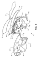
- Figure 1
- shows, in an exploded perspective view, a preferred embodiment of the vehicle front interior structure according to the invention,
- Figure 2
- shows the embodiment of the invention according to figure 1 in an assembled mode,
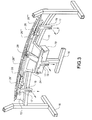
- Figure 3
- shows a first detail of the preferred embodiment of the invention,
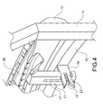
- Figure 4
- shows a second detail of the preferred embodiment of the invention,
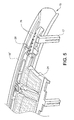
- Figure 5
- shows a third detail of the preferred embodiment of the invention, and
- Fig. 6a-6e
- shows, in a schematic side view, the function of the inventive vehicle front interior structure during a collision.
- Figure 1 schematically shows in an exploded perspective view a vehicle front interior structure 1 according to a preferred embodiment of the invention. A
cross member 10 extends transversely at some distance below awindshield 12 between theA-pillars 14 of a schematically shownvehicle body 16. Thecross member 10 provides structural rigidity and support to the vehicle and it also supports awindshield supporting member 15 comprising a curved flange 15'. Ahood 13 is also shown in figure 1. The front interior structure 1 further comprises a first, outer, dashboard member 18'; asecond dashboard member 18" forming mainair flow ducts 24 and airflow distribution ducts 26; and a heating, ventilating and air conditioning unit (HVAC-unit) 22. The HVAC-unit 22 is principally a solid box containing air treatment equipment. Themain ducts 24 lead the treated (e.g. heated) air from the HVAC-unit 22 in a diagonal forward/upwards direction to thedistribution ducts 26 arranged in parallel with thewindshield 12, whichdistribution ducts 26 guide the air flow to outlets directed towards thewindshield 12 and towards side windows. The first andsecond dashboard members 18', 18" are actually welded together as to form oneintegral dashboard unit 18 wherein thedistribution ducts 26 are formed when the twomembers 18', 18" are assembled. Theintegral dashboard member 18 is provided withfastening members 17 adapted to be fastened tobrackets 19 arranged on thevehicle body 16. As will be described further below, thefastening members 17 andbrackets 19 exhibit a detachment function such that thedashboard member 18 becomes detachably secured to thevehicle body 16. - The vehicle front interior structure 1 may of course also be provided with various other parts, such as instruments, steering column, glove compartment and airbags, which are not shown in the figures.
Openings 30 allow space for some of such parts. - The outer dashboard member 18' is, in a conventional manner, made up of a carrier covered with foam and an outer surface layer, wherein the carrier gives the dashboard member 18' a structural rigidity. However, a
front portion 21 of the outer dashboard member 18', i.e. the part of the outer dashboard member 18' that is positioned in association with a lower part of thewindshield 12, has been made much weaker than the rest of the outer dashboard member 18' by modifying the carrier in thisfront portion 21. The main function of this weakenedfront portion 21 is to significantly increase the flexibility of the dashboard in the position close to thewindshield 12 so that the curved flange 15' is allowed to absorb impact energy in an efficient manner as is further described below. Thedashboard front portion 21 should principally be as weak as possible in order to make it possible to dispense with any rigid parts in the position close to thewindshield 12, since such parts might interfere with the function of the curved flange 15'. It is sufficient if thefront portion 21 has a self-supporting strength. In the example described here theweaker front portion 21 is made of a thermo plastic elastomer and constitutes the front 60 mm portion of the outer dashboard member 18'. Due to this feature, the front portion will easily yield but also slightly contribute to the absorption of impact energy in the event of a collision. The weakenedfront portion 21 of the outer dashboard member 18' is hold in place at the lower part of thewindshield 12 by means of a flexible sealing member (not shown) that extends horizontally along thewindshield 12 and that has a clips function that is adapted to detach rather easily at an impact. - The
integral dashboard member 18, and thus thesecond dashboard member 18", is positioned such that themain ducts 24 becomes positioned on top of the HVAC-unit 22 that thus forms a duct support. The HVAC-unit 22 is inclined in a direction towards the rear of the vehicle such that themain ducts 24, and thus thedashboard members 18', 18", more easily can slide off the HVAC-unit 22 in the event of a collision. - Figure 2 shows the vehicle front interior structure 1 in an assembled mode.
- In figure 3 the outer dashboard member 18', as well as the
windshield 12 and thehood 13, have been removed in order to show thesecond dashboard member 18" and the attachment of the dashboard to thecross member 10 and other parts of thevehicle body 16. With regard to reduction of pedestrian injuries, it is important that thedistribution ducts 26 are capable of yielding when exposed to a force directed perpendicular to thewindshield 12. Since thedistribution ducts 26 are arranged essentially in parallel with thewindshield 12, thedistribution ducts 26 should thus be capable of yielding in a direction perpendicular to their longitudinal axis. As can be seen in figure 3, thedistribution ducts 26 are divided into foursections 26', 26", 26"', 26"" separated byflexible joints 28 that extend in a direction across thedistribution ducts 26. In this case theflexible joints 28 are, in principle, produced by cutting off thedistribution duct 26, normally made in ABS plastic, and re-joining the sections with a thermo plastic elastomer (TPE) with low stiffness. Preferably, theflexible joints 28 are moulded together with theduct sections 26', 26", 26"', 26"". Conventionally, thedistribution ducts 26 form a rigid transversal beam section, but by splitting them up into several parts they become flexible such that they yield in the event of a collision impact. As an alternative to the use of TPE, theflexible joints 28 could be achieved by giving the end parts of theduct sections 26', 26", 26"', 26"" a bellows design or a telescopic function. - The fastening means, i.e. the
fastening member 17 and thebracket 19, are adapted to detach when thesecond dashboard member 18" is exposed to a force exceeding a certain pre-determined limit. In most situations the force of interest is the resulting force directed diagonally backwards/downwards as indicated by the arrows. Conventional dashboards are rigid and firmly attached to the vehicle body. The main function of the inventive detaching function of thedashboard member 18 is to extend the braking distance of a pedestrian that hits thewindshield 12 and the dashboard positioned behind/below. What will happen in the event of such a collision is that, until the force reaches the pre-determined limit, part of the impact energy will be absorbed by thedashboard members 18', 18" due to inherent resilience. As the force reaches the pre-determined limit, one or several of the fastening means 17, 19 will detach; they do not necessarily have to detach simultaneously. Between the instants of time when the detachments occur, and also after the last fastening means 17, 19 has detached, further impact energy will be absorbed by thedashboard members 18', 18" due to inherent resilience. Which value to choose for this pre-determined limit depends on the over-all design of the interior structure 1, such as if there are other collapsable/detachable systems present and in which way different systems or functions co-operate. Generally, if the pre-determined limit is too low the dashboard might detach unintentionally, i.e. the dashboard may come loose in non-accidental situations, and if the pre-determined limit is too high the structure will not absorb impact energy in the intended manner. Around 0,5 kN may be regarded as a lower limit. In the example described in this text the pre-determined limit at which the dashboard member comes loose is set to 0,8 kN. A limit in the interval 0,6 - 1,0 kN would be reasonable. A value of around 1,5 kN may be regarded as an upper limit. The force at which theindividual brackets 19 orfastening members 17 should be designed to detach or collapse depends on the total number of brackets and how they are positioned. - Figure 4 shows, in an enlarged sectional perspective view, the fastening means 17, 19 used for attaching the
dashboard member 18 to thecross member 10 that forms a part of thevehicle body 16. Thebrackets 19 are made of steel and are firmly attached to thecross member 10 or other parts of thevehicle body 16. Eachbracket 19 constitutes of a vertically positioned plate extending in a backward direction, in relation to the vehicle, and is provided with a longitudinal recess 19' that is open in the rear and side directions. Thefastening members 17 are made of plastics and each fasteningmember 17 is provided with a vertical recess 17' having a width adapted to receive thebracket 19, and abreakable member 23, adapted to fit into the longitudinal recess 19'. Thebreakable member 23 is adapted to collapse when thedashboard member 18 is exposed to a downwardly directed force exceeding a certain pre-determined value. The vertical recess 17' extends in an upward direction to allow thedashboard member 18 to move downwards when thebreakable member 23 collapses. Thedashboard member 18 is easily arranged onto thebrackets 19 by pushing it in a forward direction after having adjusted its vertical position. Thebrackets 19 are designed to guide thebreakable member 23 into the longitudinal recess 19'. Various other, easily detachable fastening means (not shown), such as screws, holds thedashboard member 18 in place so that it does not slide backwards. Naturally, it is possible to use other materials than steel and plastics for thebracket 19 and thefastening member 17. In particular, various deformable material could be used to form thebreakable member 23. - Figure 5 shows a magnified view of a part of the
second dashboard member 18", as well as of thewindshield supporting member 15. Conventionally, a dashboard member constituting air flow ducts is made of ABS plastics which is a good structural material, is relatively inexpensive and is weldable. Such a rigid conventional dashboard is, however, not suitable for absorbing impact energy. With regard to reduction of pedestrian injuries, it is important that themain ducts 24 are capable of yielding when exposed to a force directed perpendicular to thewindshield 12. Since themain ducts 24 are arranged essentially perpendicular to the plane of thewindshield 12, themain ducts 24 should thus be capable of yielding in a direction along with their longitudinal axis. In contrast to a conventional dashboard, a significant portion of the inventivesecond dashboard member 18" is therefore made out of a thermo plastic elastomer (TPE) which reduces the stiffness of the structure allowing further absorbtion of impact energy in the event of a collision. Parts made of TPE are indicated by slanted, stepped, line areas in figure 5. In particular, the portions of thesecond dashboard member 18" forming themain ducts 24 are made of TPE. Figure 5 also shows the TPE in one of theflexible joints 28 that divides thedistribution ducts 26. As can be seen in figure 5 some parts are made of ABS to allow welding together with other parts of the dashboard. - As an alternative, or complement, to the use of TPE the
main ducts 24 may have a bellows or telescopic design which also reduces the stiffness of the structure. As will be further described below, the lower support of themain ducts 24 has a disconnection function achieved by a detach function and/or a geometry that allows movement of themain duct 24 such as an appropriate inclination of contact surface. - The front interior structure 1 may further be provided with load distributors (not shown) in the form of one or several relatively thin and flat plates positioned in front of the
windshield supporting member 15 below, and in the same plane as, thewindshield 12. The load distributors are adapted to transmit loads to the windshield and further to a roof structure in the event of a vehicle front crash. Since the load distributors have a flat form and are positioned in the same plane as thewindshield 12 they will, in the event of a pedestrian head impact, easily bend or collapse with a minimum of force contribution in head impact direction. - Figures 6a-6e show a schematic cross sectional view of the inventive vehicle front interior structure 1 during impact of an
object 20, such as a head of pedestrian. The figures 6a-6e are in chronological order such that in figure 6a the impact starts whereas in figure 6e the velocity of theobject 20 is zero relative to the vehicle. As shown in figure 6a thecross member 10 is positioned at a distance D1 from thewindshield 12 and the windshield-hood interface. As thecross member 10 is a rigid supporting member the distance D1 determines the total depth of the deformation zone. The distance D1 should be at least around 50 mm but a preferred value is around 110 mm.
Figure 6a also shows thewindshield supporting member 15 having a curved, C-shaped flange 15' that is positioned between thecross member 10 and thewindshield 12. Thewindshield supporting member 15 is constituted of a substantially straight lower flange member, that is fastened to thecross member 10, and a curved flange member 15' with a radius of 55 mm. The convex side of the C-shaped flange 15' is faced towards the front of the vehicle, whereas the concave side is facing the rear of the vehicle. Thewindshield supporting member 15 is attached to thecross member 10 essentially along its entire length. The C-shaped flange 15' is produced from a steel sheet with a thickness of 0,7 mm. In the example described here the wholewindshield supporting member 15 is made from the same steel sheet. In order to adapt thewindshield supporting member 15 to e.g. different vehicle interior structures it is possible to vary e.g. the steel plate thickness, within an interval of around 0,5-1,5 mm, and to modify the curvature of the flange 15'. In this regard it is important that the flexibility of the curved flange 15' is adapted to an impact corresponding to a head of a pedestrian in the event of a collision and that the curved flange 15' is adapted to be deformed in a roll-bending behaviour as further described below. - Figure 6b shows the situation slightly after impact of the
object 20 at the lower part of thewindshield 12. As shown in figure 6b thewindshield supporting member 15 has started to deform. Due to its curved cross section the flange 15' exhibits an almost constant deformation force, i.e. the force acting as to avoid further deformation. During impact the deformation of the flange 15' follows the object, i.e. the flange 15' exhibits a roll bending behaviour such that the plastic deformation zone moves continuously along the flange 15'. In contrast to a e.g. a V-shaped flange, that exhibits a force-deformation curve where, after an initial peak, the force decreases with increasing deformation, the inventive curved flange 15' exhibits a force-deformation curve where, after an initial increase, the force is essentially independent of the deformation. The inventive curved flange 15' can thus absorb a larger amount of impact energy compared to a V-shaped flange of similar dimensions. In addition to the C-shape, thewindshield supporting member 15 is slightly bent in a z-direction, i.e. in a direction parallel to thecross member 10, which enhances the tendency of exhibiting a flat force-deformation curve and which also has the effect of giving a more local deformation. In order to achieve the advantageous roll-bending effect it is important to avoid a too small radius of the curved flange member. In particular, it is important to avoid a bending indication such as a V-shape. A preferred interval of the radius is between 25 and 100 mm. - In figure 6c the
windshield supporting member 15 has been further deformed and the weakenedfront portion 21 of thedashboard member 18 has started to deform. So far, the impact energy of the object has been absorbed by thewindshield 12, thehood 13, the C-shaped flange 15' and the weakeneddashboard front portion 21. - In figure 6d the
windshield supporting member 15, as well as the weakeneddashboard front portion 21, have been further deformed. At this moment also theducts distribution ducts 26 have yielded at one or several of theflexible joints 28 whereas themain ducts 24 have started to deform due to their content of flexible material. - In figure 6e the fastening means 17, 19 has disengaged or collapsed such that the
dashboard member 18 has detached from the vehicle body 16 (including the cross member 10). Further, the duct support has been disconnected from the HVAC-unit 22 due to the inclination of the connecting surface. In figure 6e an angle α of inclination is indicated. A preferred value of this angle α for achieving a proper disconnecting function is around 20-60°. - In the front interior structure described, any supports and fixations of the front part of the dashboard, i.e. up to around 300 mm from the dashboard front edge, are detachable or deformable, i.e. when a certain force level is exceeded the support or fixation collapse or detach so that the dashboard member comes loose from the
vehicle body 16. This means that the support stiffness is considerably reduced. This function is obtained both for the dashboard itself and any system integrated into the dashboard. - A commonly used parameter in designing vehicles to be less hazardous to pedestrians is the so-called HIC (Head Injury Criteria) level which is a measure of the absorbed energy of a head of a pedestrian in the event of an accident. In principal, the HlC level is calculated from the time dependency of the retardation of the head. The lower the level of the HlC, the lower the risk of having injuries. Conventional vehicle front interior structures typically give an HlC-level of at least 2000 which results in a serious injury. To reduce serious injury in the plenum area the HlC value has to be reduced to a value below around 1000. A main reason for the high-level HlC associated with the conventional structures is that that the supporting cross member in these structures is positioned directly below the windshield thus working as a direct windshield support. Such a structure provides no deformation zone that can absorb the impact energy. In contrast, the inventive vehicle front interior structure 1 provides several different structural improvements that contribute to the absorption of the impact energy: the roll-bending behaviour of the curved windshield supporting flange 15'; the collapsable or detachable supporting 17, 19 of the
dashboard 18; and the flexibility of theduct systems - In this context the expression "dashboard member" refers to a main part of a dashboard arrangement positioned below the
windshield 12 in a vehicle. In the example described here, the dashboard arrangement comprises two main parts: the first dashboard member 18', which is the outer, visible part of the dashboard arrangement and which sometimes is referred to as an instrument panel; and thesecond dashboard member 18", which defines the major part of theducts vehicle body 16 via thecross member 10, and are, in this particular example, joined together as to form oneintegral dashboard member 18. Smaller dashboard components, such as instruments and airbags, are in turn attached to these main parts. In alternative dashboard arrangements the twodashboard members 18', 18" may be less integrated; theducts second dashboard member 18" and the twodashboard members 18', 18" may be attached to thevehicle body 14 in a more independent way than in the example described here. Further, a main dashboard member, in particular the second,concealed dashboard member 18", may be constituted of several main parts that may be individually fastened to thevehicle body 16. Any part of the dashboard arrangement that is relevant in the context of reducing injuries in collisions with pedestrians may be regarded as a "dashboard member". For instance, the dashboard arrangement may comprise an upper dashboard member positioned horizontally at the lower part of the windshield. This upper dashboard member could be detachably attached to the vehicle body and thus be regarded as the "dashboard member". In order to realize the detachable function of the dashboard member as described above it is sufficient that one of the main parts of the dashboard arrangement is detachably arranged. However, in order to make use of the advantages associated with this function it is important that other parts of the dashboard arrangement do not destroy the advantages provided by the detachable part. Therefore, these other parts should either be detachable themselves, be arranged onto the detachable part, or have a very flexible structure. The detachable dashboard member(s) can be directly or indirectly secured to the vehicle body. In the preferred embodiment of the invention shown in the figures the main,integral dashboard member 18 may be regarded as directly secured to thevehicle body 16 since only some fastening means 17, 19 are involved. As an alternative, it is possible to attach a main dashboard member to an additional dashboard member that in turn is detachably arranged onto the vehicle body. Such an additional dashboard member may be regarded as a main part of the dashboard arrangement and, thus, as the detachable "dashboard member". - With the expression that the
windshield support member 15 is adapted to absorb impact energy is meant that thewindshield support member 15 is flexible such as to allow a deformation zone to be formed in the event of an impact of e.g. a head of a pedestrian. This means, for instance, that any rigid cross member adapted to give stability to the vehicle, which cross member due to its stabilizing function would not contribute to the deformation zone in the event of an impact of a head, must be positioned at some distance from the windshield. - The invention is not limited by the embodiments described above but can be modified in various ways within the scope of the claims. For instance, it is not necessary that the various impact energy absorbing parts are activated in the same order as described in relation to figures 6a-6e.
- Further, the
windshield supporting member 15 can be designed and arranged in various ways but it is important to include a curved flange adapted to be deformed in a roll-bending manner when exposed to an impact as described above. - As an alternative to the breakable/collapsable function of the fastening means 17, 19 it is possible to use other detachable functions, such as a clips function.
- It should be noted that wording such as "detach" and "detachable function" refer both to detachable/attachable structures and structures that collapse, i.e. that become destructed when detached.
Claims (17)
- Vehicle front interior structure (1), comprising an air flow distribution duct (26) arranged essentially parallel with a windshield (12),
characterized in
that the distribution duct (26) is divided into at least two sections (26', 26", 26"', 26"") connected by a flexible joint (28) that extends in a direction essentially across the distribution duct (26). - Vehicle front interior structure (1) according to claim 1,
characterized in
that the flexible joint (28) comprises a flexible material, such as a thermo plastic elastomer, arranged to connect adjacent distribution duct sections (26', 26", 26"', 26""). - Vehicle front interior structure (1) according to claim 1 or 2,
characterized in
that the air flow distribution duct (26) is integrated into a dashboard member (18, 18', 18"). - Vehicle front interior structure (1) according to anyone of the above claims,
characterized in
that it comprises a dashboard member (18, 18', 18") being directly or indirectly secured to a vehicle body (10, 16), wherein the dashboard member (18, 18', 18") is adapted to detach from the vehicle body (16) when the dashboard member (18, 18', 18") is exposed to a force exceeding a pre-determined limit. - Vehicle front interior structure (1) according to claim 4,
characterized in
that the dashboard member (18, 18', 18") is secured to the vehicle body (10, 16) using fastening means (17, 19) comprising a fastening member (17), attached to the dashboard member (18, 18', 18"), and a bracket (19), attached to the vehicle body (10, 16), wherein the fastening means (17, 19) comprises a breakable member (23) adapted to collapse when exposed to a force exceeding a pre-determined limit. - Vehicle front interior structure (1) according to claim 4 or 5,
characterized in
that the pre-determined limit of the force is in the range 0,5-1,5 kN, - Vehicle front interior structure (1) according to anyone of the above claims,
characterized in
that it comprises a windshield support member (15) adapted to absorb impact energy in the event of a collision with e.g. a pedestrian. - Vehicle front interior structure (1) according to claim 7,
characterized in
that the windshield support member (15) comprises a curved flange (15') adapted to support a lower part of the windshield (12) and to be deformed in a roll-bending manner when exposed to an impact. - Vehicle front interior structure (1) according to claim 8,
characterized in
that the curved flange (15') extends along a lower part of the windshield (12). - Vehicle front interior structure (1) according to claim 8 or 9,
characterized in
that the curved flange (15') has a radius (R) between 25 and 100 mm. - Vehicle front interior structure (1) according to claim 10,
characterized in
that the curved flange (15') has a radius (R) between 50 and 60 mm. - Vehicle front interior structure (1) according to anyone of claims 8 to 11,
characterized in
that the curved flange (15') has a convex side directed in a forward direction. - Vehicle front interior structure (1) according to anyone of claims 7 to 12,
characterized in
that the windshield support member (15) is attached to a supporting cross member (10). - Vehicle front interior structure (1) according to claim 13,
characterized in
that the supporting cross member (10) is positioned at least 50 mm, preferably at least 75 mm, more preferably at least 100 mm, from the windshield (12). - Vehicle front interior structure (1) according to anyone of the above claims,
characterized in
that it comprises an air flow main duct (24) arranged to lead air upwards from an HVAC-unit (22), wherein the main duct (24) is at least partly formed in a flexible material, such as a thermo plastic elastomer. - Vehicle front interior structure (1) according to claim 15,
characterized in
that the HVAC-unit (22) is arranged below the main duct (24) wherein a connection surface between the main duct (24) and the HVAC-unit (22) is inclined in a rear direction. - Vehicle front interior structure (1) according to anyone of the above claims,
characterized in
that a front portion (21) of a dashboard member (18, 18', 18") positioned in connection with the windshield (12) is arranged to be considerable weaker than the main parts of the remaining portion of the dashboard member (18, 18', 18")
Priority Applications (2)
| Application Number | Priority Date | Filing Date | Title |
|---|---|---|---|
| EP06100401A EP1808364B1 (en) | 2006-01-16 | 2006-01-16 | Vehicle front interior structure |
| US11/623,536 US20070164586A1 (en) | 2006-01-16 | 2007-01-16 | Vehicle front interior structure |
Applications Claiming Priority (1)
| Application Number | Priority Date | Filing Date | Title |
|---|---|---|---|
| EP06100401A EP1808364B1 (en) | 2006-01-16 | 2006-01-16 | Vehicle front interior structure |
Publications (2)
| Publication Number | Publication Date |
|---|---|
| EP1808364A1 true EP1808364A1 (en) | 2007-07-18 |
| EP1808364B1 EP1808364B1 (en) | 2011-08-24 |
Family
ID=36581597
Family Applications (1)
| Application Number | Title | Priority Date | Filing Date |
|---|---|---|---|
| EP06100401A Expired - Lifetime EP1808364B1 (en) | 2006-01-16 | 2006-01-16 | Vehicle front interior structure |
Country Status (2)
| Country | Link |
|---|---|
| US (1) | US20070164586A1 (en) |
| EP (1) | EP1808364B1 (en) |
Cited By (2)
| Publication number | Priority date | Publication date | Assignee | Title |
|---|---|---|---|---|
| WO2011010053A1 (en) * | 2009-07-21 | 2011-01-27 | Faurecia Interieur Industrie | Motor vehicle dashboard structure, and motor vehicle comprising such a structure |
| RU2671443C2 (en) * | 2014-03-10 | 2018-10-31 | ФОРД ГЛОУБАЛ ТЕКНОЛОДЖИЗ, ЭлЭлСи | Active bolster for pedestrian protection |
Families Citing this family (8)
| Publication number | Priority date | Publication date | Assignee | Title |
|---|---|---|---|---|
| DE102011012524A1 (en) * | 2011-02-26 | 2012-08-30 | GM Global Technology Operations LLC (n. d. Gesetzen des Staates Delaware) | Motor vehicle body for use with elastically suspended windscreen, comprises suspension for windshield, which is provided in intermediate space between lower front edge of windshield and substructure |
| DE102011100687A1 (en) * | 2011-05-06 | 2012-11-08 | GM Global Technology Operations LLC (n. d. Gesetzen des Staates Delaware) | Instrument panel assembly |
| US8596712B2 (en) * | 2011-07-01 | 2013-12-03 | Honda Motor Co., Ltd. | Vehicle cabin intrusion management |
| DE102011111237A1 (en) * | 2011-08-20 | 2013-02-21 | GM Global Technology Operations LLC (n. d. Gesetzen des Staates Delaware) | Automotive body |
| US10597082B2 (en) | 2015-06-26 | 2020-03-24 | Ford Global Technologies, Llc | Bracket for improved impact loading performance |
| US11021126B1 (en) * | 2017-06-30 | 2021-06-01 | Apple Inc. | Windshield area intrusion control |
| EP3508399B1 (en) * | 2018-01-09 | 2023-02-22 | Motherson Innovations Company Limited | Self-supporting carrier structure for an instrument panel in a vehicle, instrument panel comprising such a carrier structure and vehicle with such an instrument panel |
| DE102024200844A1 (en) * | 2024-01-31 | 2025-07-31 | Stellantis Auto Sas | Dashboard arrangement for motor vehicles and motor vehicles |
Citations (9)
| Publication number | Priority date | Publication date | Assignee | Title |
|---|---|---|---|---|
| US5678877A (en) | 1993-05-14 | 1997-10-21 | Kansei Corporation | Structure of instrument panel portion for use in vehicles |
| DE19626441A1 (en) * | 1996-06-20 | 1998-01-15 | Sommer Allibert Lignotock Gmbh | Dashboard for vehicle |
| US6193305B1 (en) | 1998-07-24 | 2001-02-27 | Honda Giken Kogyo Kabushiki Kaisha | Windshield supporting structure |
| US6193304B1 (en) | 1998-05-12 | 2001-02-27 | Honda Giken Kogyo Kabushiki Kaisha | Windshield supporting structure |
| US6447041B1 (en) | 2000-09-06 | 2002-09-10 | Visteon Global Technologies, Inc. | Integrated HVAC and steering column support structure |
| US6520849B1 (en) | 2000-03-31 | 2003-02-18 | Delphi Technologies, Inc. | Integrated structural HVAC system |
| EP1371510A1 (en) * | 2002-06-10 | 2003-12-17 | Honda Giken Kogyo Kabushiki Kaisha | Vehicle windshield mounting structure |
| JP2004034832A (en) | 2002-07-03 | 2004-02-05 | Gp Daikyo Corp | Structure of outside air introduction duct for vehicles |
| FR2853043A1 (en) * | 2003-03-26 | 2004-10-01 | Hutchinson | Hose for vehicles air conditioning system, has swivel joint providing connection between rigid and flexible parts, and satisfying rotation function, sealing function, and locking or axial hold function between parts |
Family Cites Families (7)
| Publication number | Priority date | Publication date | Assignee | Title |
|---|---|---|---|---|
| JPH0535892Y2 (en) * | 1987-12-25 | 1993-09-10 | ||
| JP3052731B2 (en) * | 1994-05-10 | 2000-06-19 | 三菱自動車工業株式会社 | Car steering system |
| US5765310A (en) * | 1996-10-01 | 1998-06-16 | Gold; Peter N. | Frangible vehicle window panel mounting bracket |
| SE514218C2 (en) * | 1999-05-25 | 2001-01-22 | Volvo Personvagnar Ab | Device for hinges for bonnets on passenger cars |
| JP3811346B2 (en) * | 2000-11-10 | 2006-08-16 | 本田技研工業株式会社 | Instrument panel for vehicle-duct assembly for air conditioning |
| CN1309595C (en) * | 2001-10-17 | 2007-04-11 | 大众汽车有限公司 | Ventilation device for a vehicle |
| US6688680B1 (en) * | 2002-12-17 | 2004-02-10 | Bayer Polymers Llc | Molded cross vehicle beam |
-
2006
- 2006-01-16 EP EP06100401A patent/EP1808364B1/en not_active Expired - Lifetime
-
2007
- 2007-01-16 US US11/623,536 patent/US20070164586A1/en not_active Abandoned
Patent Citations (9)
| Publication number | Priority date | Publication date | Assignee | Title |
|---|---|---|---|---|
| US5678877A (en) | 1993-05-14 | 1997-10-21 | Kansei Corporation | Structure of instrument panel portion for use in vehicles |
| DE19626441A1 (en) * | 1996-06-20 | 1998-01-15 | Sommer Allibert Lignotock Gmbh | Dashboard for vehicle |
| US6193304B1 (en) | 1998-05-12 | 2001-02-27 | Honda Giken Kogyo Kabushiki Kaisha | Windshield supporting structure |
| US6193305B1 (en) | 1998-07-24 | 2001-02-27 | Honda Giken Kogyo Kabushiki Kaisha | Windshield supporting structure |
| US6520849B1 (en) | 2000-03-31 | 2003-02-18 | Delphi Technologies, Inc. | Integrated structural HVAC system |
| US6447041B1 (en) | 2000-09-06 | 2002-09-10 | Visteon Global Technologies, Inc. | Integrated HVAC and steering column support structure |
| EP1371510A1 (en) * | 2002-06-10 | 2003-12-17 | Honda Giken Kogyo Kabushiki Kaisha | Vehicle windshield mounting structure |
| JP2004034832A (en) | 2002-07-03 | 2004-02-05 | Gp Daikyo Corp | Structure of outside air introduction duct for vehicles |
| FR2853043A1 (en) * | 2003-03-26 | 2004-10-01 | Hutchinson | Hose for vehicles air conditioning system, has swivel joint providing connection between rigid and flexible parts, and satisfying rotation function, sealing function, and locking or axial hold function between parts |
Cited By (3)
| Publication number | Priority date | Publication date | Assignee | Title |
|---|---|---|---|---|
| WO2011010053A1 (en) * | 2009-07-21 | 2011-01-27 | Faurecia Interieur Industrie | Motor vehicle dashboard structure, and motor vehicle comprising such a structure |
| FR2948325A1 (en) * | 2009-07-21 | 2011-01-28 | Faurecia Interieur Ind | AUTOMOTIVE VEHICLE DASHBOARD STRUCTURE AND MOTOR VEHICLE HAVING SUCH A STRUCTURE. |
| RU2671443C2 (en) * | 2014-03-10 | 2018-10-31 | ФОРД ГЛОУБАЛ ТЕКНОЛОДЖИЗ, ЭлЭлСи | Active bolster for pedestrian protection |
Also Published As
| Publication number | Publication date |
|---|---|
| EP1808364B1 (en) | 2011-08-24 |
| US20070164586A1 (en) | 2007-07-19 |
Similar Documents
| Publication | Publication Date | Title |
|---|---|---|
| US20070164586A1 (en) | Vehicle front interior structure | |
| JP4105658B2 (en) | Fender support for automobiles | |
| US7997548B2 (en) | Vehicle shifter mounting bracket system and method | |
| US7913790B2 (en) | Structure of instrument panel area of vehicle | |
| US7325861B2 (en) | Structural component of a motor vehicle bumper arrangement | |
| EP1810892B1 (en) | Vehicle front interior structure | |
| US8528964B2 (en) | Body structure with a pane cross member for a motor vehicle with a windshield | |
| CN101541623A (en) | Crossbar for dashboard of automobile and corresponding automobile | |
| US20120056446A1 (en) | Energy-Absorbing Cowl Structure | |
| CN102470756B (en) | Motor vehicle dashboard structure, and motor vehicle comprising such a structure | |
| US9834254B2 (en) | Motor vehicle instrument panel with sliding cover over crush space | |
| US9783152B2 (en) | Vehicle impact reduction structure | |
| EP1810893A1 (en) | Vehicle front interior structure | |
| JP4845510B2 (en) | Vehicle knee protector | |
| US7832764B2 (en) | Knee protector structure for vehicle | |
| US7334816B2 (en) | Knee protection device for occupants of a motor vehicle | |
| US20050156421A1 (en) | Knee impact guard for motor vehicles | |
| JP2962508B2 (en) | Cockpit in the interior room of a car | |
| JPH0585226A (en) | Instrument panel structure for automobile | |
| JP4802617B2 (en) | Automotive bonnet | |
| JP4763384B2 (en) | Vehicle knee protector structure | |
| JP4744923B2 (en) | Vehicle knee protector structure | |
| CN114929565A (en) | Driver's cabin for vehicle | |
| US11608026B2 (en) | Energy absorbing member beneath vehicle hood | |
| CN224145902U (en) | Front bumper assembly and vehicle |
Legal Events
| Date | Code | Title | Description |
|---|---|---|---|
| PUAI | Public reference made under article 153(3) epc to a published international application that has entered the european phase |
Free format text: ORIGINAL CODE: 0009012 |
|
| AK | Designated contracting states |
Kind code of ref document: A1 Designated state(s): AT BE BG CH CY CZ DE DK EE ES FI FR GB GR HU IE IS IT LI LT LU LV MC NL PL PT RO SE SI SK TR |
|
| AX | Request for extension of the european patent |
Extension state: AL BA HR MK YU |
|
| 17P | Request for examination filed |
Effective date: 20071115 |
|
| AKX | Designation fees paid |
Designated state(s): DE GB SE |
|
| 17Q | First examination report despatched |
Effective date: 20080911 |
|
| GRAP | Despatch of communication of intention to grant a patent |
Free format text: ORIGINAL CODE: EPIDOSNIGR1 |
|
| GRAS | Grant fee paid |
Free format text: ORIGINAL CODE: EPIDOSNIGR3 |
|
| GRAA | (expected) grant |
Free format text: ORIGINAL CODE: 0009210 |
|
| AK | Designated contracting states |
Kind code of ref document: B1 Designated state(s): DE GB SE |
|
| REG | Reference to a national code |
Ref country code: GB Ref legal event code: FG4D |
|
| RAP2 | Party data changed (patent owner data changed or rights of a patent transferred) |
Owner name: VOLVO CAR CORPORATION |
|
| REG | Reference to a national code |
Ref country code: DE Ref legal event code: R096 Ref document number: 602006023943 Country of ref document: DE Effective date: 20111027 |
|
| REG | Reference to a national code |
Ref country code: SE Ref legal event code: TRGR |
|
| REG | Reference to a national code |
Ref country code: DE Ref legal event code: R081 Ref document number: 602006023943 Country of ref document: DE Owner name: VOLVO CAR CORPORATION, SE Free format text: FORMER OWNER: FORD GLOBAL TECHNOLOGIES, LLC, DEARBORN, US Effective date: 20111125 Ref country code: DE Ref legal event code: R081 Ref document number: 602006023943 Country of ref document: DE Owner name: VOLVO CAR CORPORATION, SE Free format text: FORMER OWNER: FORD GLOBAL TECHNOLOGIES, LLC, DEARBORN, US Effective date: 20110901 Ref country code: DE Ref legal event code: R081 Ref document number: 602006023943 Country of ref document: DE Owner name: VOLVO CAR CORPORATION, SE Free format text: FORMER OWNER: FORD GLOBAL TECHNOLOGIES, LLC, DEARBORN, MICH., US Effective date: 20111125 Ref country code: DE Ref legal event code: R081 Ref document number: 602006023943 Country of ref document: DE Owner name: VOLVO CAR CORPORATION, SE Free format text: FORMER OWNER: FORD GLOBAL TECHNOLOGIES, LLC, DEARBORN, MICH., US Effective date: 20110901 |
|
| PLBE | No opposition filed within time limit |
Free format text: ORIGINAL CODE: 0009261 |
|
| STAA | Information on the status of an ep patent application or granted ep patent |
Free format text: STATUS: NO OPPOSITION FILED WITHIN TIME LIMIT |
|
| 26N | No opposition filed |
Effective date: 20120525 |
|
| REG | Reference to a national code |
Ref country code: DE Ref legal event code: R097 Ref document number: 602006023943 Country of ref document: DE Effective date: 20120525 |
|
| PGFP | Annual fee paid to national office [announced via postgrant information from national office to epo] |
Ref country code: GB Payment date: 20150120 Year of fee payment: 10 Ref country code: SE Payment date: 20150123 Year of fee payment: 10 |
|
| GBPC | Gb: european patent ceased through non-payment of renewal fee |
Effective date: 20160116 |
|
| PG25 | Lapsed in a contracting state [announced via postgrant information from national office to epo] |
Ref country code: GB Free format text: LAPSE BECAUSE OF NON-PAYMENT OF DUE FEES Effective date: 20160116 |
|
| PG25 | Lapsed in a contracting state [announced via postgrant information from national office to epo] |
Ref country code: SE Free format text: LAPSE BECAUSE OF NON-PAYMENT OF DUE FEES Effective date: 20160117 |
|
| PGFP | Annual fee paid to national office [announced via postgrant information from national office to epo] |
Ref country code: DE Payment date: 20241209 Year of fee payment: 20 |
|
| REG | Reference to a national code |
Ref country code: DE Ref legal event code: R071 Ref document number: 602006023943 Country of ref document: DE |