EP1808077A1 - Treatment means introduction member, stent delivery catheter, and pipeline system - Google Patents
Treatment means introduction member, stent delivery catheter, and pipeline system Download PDFInfo
- Publication number
- EP1808077A1 EP1808077A1 EP05783371A EP05783371A EP1808077A1 EP 1808077 A1 EP1808077 A1 EP 1808077A1 EP 05783371 A EP05783371 A EP 05783371A EP 05783371 A EP05783371 A EP 05783371A EP 1808077 A1 EP1808077 A1 EP 1808077A1
- Authority
- EP
- European Patent Office
- Prior art keywords
- stent
- conduit
- treatment instrument
- installation member
- distal end
- Prior art date
- Legal status (The legal status is an assumption and is not a legal conclusion. Google has not performed a legal analysis and makes no representation as to the accuracy of the status listed.)
- Granted
Links
Images





Classifications
-
- A—HUMAN NECESSITIES
- A61—MEDICAL OR VETERINARY SCIENCE; HYGIENE
- A61F—FILTERS IMPLANTABLE INTO BLOOD VESSELS; PROSTHESES; DEVICES PROVIDING PATENCY TO, OR PREVENTING COLLAPSING OF, TUBULAR STRUCTURES OF THE BODY, e.g. STENTS; ORTHOPAEDIC, NURSING OR CONTRACEPTIVE DEVICES; FOMENTATION; TREATMENT OR PROTECTION OF EYES OR EARS; BANDAGES, DRESSINGS OR ABSORBENT PADS; FIRST-AID KITS
- A61F2/00—Filters implantable into blood vessels; Prostheses, i.e. artificial substitutes or replacements for parts of the body; Appliances for connecting them with the body; Devices providing patency to, or preventing collapsing of, tubular structures of the body, e.g. stents
- A61F2/82—Devices providing patency to, or preventing collapsing of, tubular structures of the body, e.g. stents
- A61F2/94—Stents retaining their form, i.e. not being deformable, after placement in the predetermined place
-
- A—HUMAN NECESSITIES
- A61—MEDICAL OR VETERINARY SCIENCE; HYGIENE
- A61F—FILTERS IMPLANTABLE INTO BLOOD VESSELS; PROSTHESES; DEVICES PROVIDING PATENCY TO, OR PREVENTING COLLAPSING OF, TUBULAR STRUCTURES OF THE BODY, e.g. STENTS; ORTHOPAEDIC, NURSING OR CONTRACEPTIVE DEVICES; FOMENTATION; TREATMENT OR PROTECTION OF EYES OR EARS; BANDAGES, DRESSINGS OR ABSORBENT PADS; FIRST-AID KITS
- A61F2/00—Filters implantable into blood vessels; Prostheses, i.e. artificial substitutes or replacements for parts of the body; Appliances for connecting them with the body; Devices providing patency to, or preventing collapsing of, tubular structures of the body, e.g. stents
- A61F2/95—Instruments specially adapted for placement or removal of stents or stent-grafts
- A61F2/962—Instruments specially adapted for placement or removal of stents or stent-grafts having an outer sleeve
- A61F2/966—Instruments specially adapted for placement or removal of stents or stent-grafts having an outer sleeve with relative longitudinal movement between outer sleeve and prosthesis, e.g. using a push rod
-
- A—HUMAN NECESSITIES
- A61—MEDICAL OR VETERINARY SCIENCE; HYGIENE
- A61B—DIAGNOSIS; SURGERY; IDENTIFICATION
- A61B1/00—Instruments for performing medical examinations of the interior of cavities or tubes of the body by visual or photographical inspection, e.g. endoscopes; Illuminating arrangements therefor
- A61B1/012—Instruments for performing medical examinations of the interior of cavities or tubes of the body by visual or photographical inspection, e.g. endoscopes; Illuminating arrangements therefor characterised by internal passages or accessories therefor
- A61B1/018—Instruments for performing medical examinations of the interior of cavities or tubes of the body by visual or photographical inspection, e.g. endoscopes; Illuminating arrangements therefor characterised by internal passages or accessories therefor for receiving instruments
-
- A—HUMAN NECESSITIES
- A61—MEDICAL OR VETERINARY SCIENCE; HYGIENE
- A61F—FILTERS IMPLANTABLE INTO BLOOD VESSELS; PROSTHESES; DEVICES PROVIDING PATENCY TO, OR PREVENTING COLLAPSING OF, TUBULAR STRUCTURES OF THE BODY, e.g. STENTS; ORTHOPAEDIC, NURSING OR CONTRACEPTIVE DEVICES; FOMENTATION; TREATMENT OR PROTECTION OF EYES OR EARS; BANDAGES, DRESSINGS OR ABSORBENT PADS; FIRST-AID KITS
- A61F2/00—Filters implantable into blood vessels; Prostheses, i.e. artificial substitutes or replacements for parts of the body; Appliances for connecting them with the body; Devices providing patency to, or preventing collapsing of, tubular structures of the body, e.g. stents
- A61F2/0095—Packages or dispensers for prostheses or other implants
-
- A—HUMAN NECESSITIES
- A61—MEDICAL OR VETERINARY SCIENCE; HYGIENE
- A61F—FILTERS IMPLANTABLE INTO BLOOD VESSELS; PROSTHESES; DEVICES PROVIDING PATENCY TO, OR PREVENTING COLLAPSING OF, TUBULAR STRUCTURES OF THE BODY, e.g. STENTS; ORTHOPAEDIC, NURSING OR CONTRACEPTIVE DEVICES; FOMENTATION; TREATMENT OR PROTECTION OF EYES OR EARS; BANDAGES, DRESSINGS OR ABSORBENT PADS; FIRST-AID KITS
- A61F2/00—Filters implantable into blood vessels; Prostheses, i.e. artificial substitutes or replacements for parts of the body; Appliances for connecting them with the body; Devices providing patency to, or preventing collapsing of, tubular structures of the body, e.g. stents
- A61F2/95—Instruments specially adapted for placement or removal of stents or stent-grafts
- A61F2/9517—Instruments specially adapted for placement or removal of stents or stent-grafts handle assemblies therefor
-
- A—HUMAN NECESSITIES
- A61—MEDICAL OR VETERINARY SCIENCE; HYGIENE
- A61F—FILTERS IMPLANTABLE INTO BLOOD VESSELS; PROSTHESES; DEVICES PROVIDING PATENCY TO, OR PREVENTING COLLAPSING OF, TUBULAR STRUCTURES OF THE BODY, e.g. STENTS; ORTHOPAEDIC, NURSING OR CONTRACEPTIVE DEVICES; FOMENTATION; TREATMENT OR PROTECTION OF EYES OR EARS; BANDAGES, DRESSINGS OR ABSORBENT PADS; FIRST-AID KITS
- A61F2/00—Filters implantable into blood vessels; Prostheses, i.e. artificial substitutes or replacements for parts of the body; Appliances for connecting them with the body; Devices providing patency to, or preventing collapsing of, tubular structures of the body, e.g. stents
- A61F2/02—Prostheses implantable into the body
- A61F2/04—Hollow or tubular parts of organs, e.g. bladders, tracheae, bronchi or bile ducts
- A61F2002/041—Bile ducts
-
- A—HUMAN NECESSITIES
- A61—MEDICAL OR VETERINARY SCIENCE; HYGIENE
- A61M—DEVICES FOR INTRODUCING MEDIA INTO, OR ONTO, THE BODY; DEVICES FOR TRANSDUCING BODY MEDIA OR FOR TAKING MEDIA FROM THE BODY; DEVICES FOR PRODUCING OR ENDING SLEEP OR STUPOR
- A61M25/00—Catheters; Hollow probes
- A61M25/002—Packages specially adapted therefor ; catheter kit packages
Definitions
- the present invention relates to a treatment instrument installation member, a stent delivery catheter provided with the treatment instrument installation member and a conduit system.
- stenosis develops at the bile duct or the like inside the human body
- it is well known to secure a passage of the bile duct or the like by inserting an elongated tubular stent into the bile duct or the like and further inserting through the stent inside of the stenotic area.
- the stent is provided on an elongated guide member, and a guide member is inserted through a conduit of an endoscope into the inside of the bile duct or the like from the tip of the endoscope and then the stent is pushed out of the guide member.
- the stent is provided with flaps and by opening these flaps the stent is prevented from being dislodged from the stenosis area.
- a stent installation member to guide the stent into the conduit of endoscope has been used.
- the stent installation member has substantially the same inner diameter as the opening of the insertion slot of the conduit and the stent installation member is made so that the stent provided inside of the stent installation member is guided into the conduit if the stent installation member is pressed against the surroundings of the insertion slot of the conduit.
- Patent Document 1 Japanese Unexamined Patent Application, First Publication No. H11-76412
- the conduit of the endoscope is divaricated into branches to perform insufflations or the like and the diameter of the conduit is larger at the bifurcation, and therefore, when the stent is passing through the bifurcation, the flaps may open because the diameter of the conduit is larger there. If the flap opens at the bifurcation, it may be bent when the flap is further inserted into the conduit which has a diameter smaller than that of the bifurcation. Therefore, even if the flaps are protected at the time of insertion at the insertion slot of the conduit, if the conduit has an area with a larger diameter than that of the insertion slot, the flap may be bent or the like.
- a bent flap as mentioned above tends to be caught by a support pillar provided at the distal end of the endoscope making it difficult to push the stent out of the endoscope.
- a support pillar provided at the distal end of the endoscope making it difficult to push the stent out of the endoscope.
- the stent in the case of using a guide wire, papilotomy knife or angiographic catheter, it is known that if there is bending at the tip of a sheath, it is easy to become caught at the bifurcation.
- This invention was made considering the above-mentioned situations and its purpose is to be able to place the stent within the human body without fail.
- a treatment instrument installation member which is used when the first treatment instrument is inserted into the first conduit of the conduit system that includes the first conduit provided with an inner diameter through which the first treatment instrument can be inserted and the second conduit provided with an inner diameter through which the second treatment instrument can be inserted, and the main conduit provided with an inner diameter through which the first and the second treatment instrument can be inserted and a connection part that connects the first conduit, second conduit and the main conduit together.
- the treatment instrument insertion member is comprised of a main body which has an outer diameter that can be inserted into the first conduit and a distal end part located on the distal end of the main body that has a blocking part which blocks at least a part of the opening through which the second conduit communicates to the connection part.
- the diameter of the first conduit through which the first treatment instrument is inserted decreases because if the main body is inserted into the first conduit, the distal end of the main body blocks a part of the opening at the connection part.
- the main body of the above mentioned treatment instrument installation member is a tubular member which has an outer diameter smaller than the inner diameter of the first conduit and that of the connection part and is provided with an inner diameter larger than that of the outer diameter of the first treatment instrument, and the distal end portion is exposed from the conduit system at the insertion slot which is provided on a side where the operating area for the conduit system is provided while the distal end part blocking at least a part of the opening communicating with the second conduit at the connection part.
- a conduit which has a smaller inner diameter than that of the connection part is created by the main body through which the first treatment instrument is inserted.
- the main body of the above mentioned treatment instrument installation member is provided with a regulative part on its proximal end which regulates the installation amount of the main body into the first conduit.
- an insertion into the correct location can be achieved by the installation amount being regulated by the regulative part.
- a stent delivery catheter is provided that is used with an endoscope including the first conduit provided with an inner diameter through which the first treatment instrument can be inserted, the second conduit provided with an inner diameter through which the second treatment instrument can be inserted, the main conduit provided with an inner diameter through which the first and the second treatment instrument can be inserted and a connection part that connects the first conduit, second conduit and the main conduit together.
- the stent delivery catheter comprises a guide member inserted into the first conduit and the main conduit from the insertion slot for the first treatment instrument provided at the operation area of the endoscope, a stent which is movable forward and backward which is provided on the guide member, a pushing member which is movable forward and backward which is provided on the guide member to push the stent out of the guide member to be placed in the human body, and a stent installation member which corresponds the above-mentioned treatment instrument installation member which is movable forward and backward which is provided on the pushing member and on the stent.
- the insertion of the stent can be performed with a part of the opening of the connection part blocked by the stent installation member, and therefore the bending of the flap of the stent, which is caused by the opening of the flap, is prevented when the stent is passing through the connection part.
- the stent of the above mentioned stent delivery catheter is provided with flaps which regulate the movement of the stent, and the stent delivery catheter is provided with a protective case which covers the stent with its flaps open and with the stent provided on the guide member.
- flaps of the stent are prevented from being bent during storage by being provided with a protection case.
- an endoscope treatment system provided with the endoscope and the stent delivery catheter is provided.
- the stent can be inserted in the correct condition because the flap of the stent is prevented from being bent at the connection part when the stent is inserted into the human body.
- a conduit system which comprises the first conduit which is provided with an inner diameter through which the treatment instrument can be inserted, the second conduit which is provided with an inner diameter through which the second treatment instrument can be inserted, the main conduit which is provided with an inner diameter through which the first and the second treatment instrument can be inserted, a connection part which connects the first conduit, second conduit and the main conduit together, and a regulative member which is provided at the connection part and prevents the first treatment instrument inserted from the first conduit from proceeding into the second conduit and at the same time enables the second treatment instrument inserted from the second conduit to proceed into the main conduit.
- a stent installation method is provided which is utilized when the stent, which has flaps on its distal end and proximal end each to be placed in the human body, is inserted from the insertion slot provided on the divaricated conduit divaricated at the bifurcation from the main conduit of the endoscope which has an opening on its distal end.
- the stent installation method includes a stent installation member insertion process and stent insertion process.
- the stent installation member insertion process is to insert the stent installation member, through which the stent can be inserted and which is longer than the route from the insertion slot to the bifurcation of the main conduit, from the insertion slot of the divaricated conduit and to enable the distal end of the stent installation member to pass through the bifurcation and to reach the main conduit after placing at least the flap of the stent provided on the proximal end of the stent inside of the stent installation member.
- the stent insertion process is to make at least the flap of the stent provided on its proximal end pass through the bifurcation by passing through the stent installation member after the stent installation member insertion process.
- the flap of the stent is prevented from opening at the bifurcation by reducing the apparent diameter of the conduit at the bifurcation when the stent is passing through the bifurcation. As a result, unnecessary force is not applied on the flap when the stent is proceeding to the main conduit from the bifurcation.
- FIG. 1 is a view showing a stent delivery catheter according to a first embodiment of the present invention inserted through an endoscope and
- FIG. 2 is an enlarged view of the cross section of part A of FIG. 1.
- an endoscope 1 has an endoscope operation part 2 that an operator operates and, on the tip of the endoscope operation part 2, an endoscope insertion part 3 is provided to be inserted into the human body.
- the endoscope insertion part 3 is flexible and can be bent by a knob 4 of the endoscope operation part 2.
- a treatment instrument insertion channel 5, which is a conduit system, is provided inside of the endoscope 1.
- a distal end 6 of the treatment instrument insertion channel 5 has an opening on the side of the distal end 6 of the endoscope insertion part 3 and communicates with the endoscope operation part 2 through the endoscope insertion part 3.
- the treatment instrument insertion channel 5 comprises a main conduit 7 which communicates with the distal end 6 of the endoscope insertion part 3 and a first conduit 9, and is divaricated to a second conduit 10 at a bifurcation 8 which is a connection part.
- the second conduit 10 extends along the axis of the main conduit 7 and communicates with a liquid supply conduit and air supply conduit which are both not shown, and can supply normal saline as a second treatment instrument.
- the liquid supply conduit or the air supply conduit are communicate with a liquid supply apparatus or an air supply apparatus provided outside via a universal cord 11 which extends from the side of the endoscope operation part 2 as shown in FIG. 1.
- the first conduit 9 is extended to an insertion slot 12 provided on the side of the endoscope operation part 2.
- a stent delivery catheter 20 is inserted as the first treatment instrument into the insertion slot 12.
- the stent delivery catheter 20 has an operation part 21 with which an operator operates.
- An operation part 21 comprises a mouth ring 22 for a guide catheter and a mouth ring 23 for a pusher tube which is removably provided on the mouth ring 22 for a guide catheter.
- the mouth ring 23 for a pusher tube is provided with a pusher tube 24 on the distal end of the mouth ring 23 for a pusher tube.
- the pusher tube 24 comprises a flexible elongated tubular member.
- a guide catheter 25, which is a guide member, is movably inserted forward and backward through the pusher tube 24.
- the guide catheter 25 comprises a flexible member and is provided with lumens and a marker 26 for X-ray imaging which is buried on the distal end of the guide catheter 25.
- the lumens which is passing through inside of the mouth ring 23 for a pusher tube, and communicate with a connection part 27 provided on the proximal end of the mouth ring 22 for a guide catheter.
- the connection part 27 comprises a luer-lock or the like and can communicate with syringes or the like which are not shown in figures.
- the guide catheter 25 is longer than the pusher tube 24 and the distal end of the guide catheter 25 is exposed from the distal end of the pusher tube 24 when the mouth ring 22 for a guide catheter and the mouth ring 23 for a pusher tube are connected.
- a stent 30 is movably provided forward and backward around the exposing distal end 25a.
- the stent 30 is provided with a tubular main stent body 31.
- the inner diameter of a main stent body 31 is substantially the same as the outer diameter of the guide catheter 25.
- the outer diameter of the main stent body 31 is smaller than the inner diameters of those of the main conduit 7 or the bifurcation 8 or the first conduit 9.
- a flap 32 is provided on the distal end of the stent 30.
- Four flaps 32 are provided on the circumference of the stent main body 31 and each of the flaps has a 90-degree interval with adjacent flaps, and when a pressure is not applied they are made to open toward the proximal end of the stent 30 by lifting the tip of the flap which is closer to the proximal end.
- Each of the four flaps 32 is made so as to gradually reduce its width from the proximal end, which is connected to the main stent body 31, to its distal end.
- Four flaps 33 are provided on the proximal end of the stent 30.
- the flaps 33 have the same structure as the flaps 32 except that when a pressure is not applied they are made to open toward the distal end of the stent 30 by lifting the four tips of the flap closer to the distal end.
- a stent installation member 35 is movably provided forward and backward around the pusher tube 24.
- the stent installation member 35 comprises a tubular main body 35a and the inner diameter of the tubular main body 35a is larger than the outer diameter of the pusher tube 24.
- the inner diameter of the stent installation member 35 is larger than the outer diameter of the stent 30 in a state where both the flaps 32 and 33 are closed.
- the outer diameter of the stent installation member 35 is smaller than the inner diameter of the first conduit 9 which is located closer to the endoscope 1 and the inner diameter of the bifurcation 8.
- the length of the stent installation member 35 is longer than the total length of the first conduit 9 and is shorter than the pusher tube 24 and more preferably, it is approximately 90 mm.
- the stent installation member 35 as described above is made of fluorine resin (including PTFE, PFT, FEP or the like) or polyethylene resin or the like. The reason for this is because the stent installation member 35 should be thin, rigid and smooth enough to enable the insertion of the stent installation member 35 into the first conduit 9. And in the stent installation member 35, at least a distal end 35b thereof may be made to be deformable.
- a structure which enables the distal end 35b of the stent installation member 35 to be deformable is achieved by making, for example, the whole stent installation member 35 or the distal end 35b of the stent installation member 35 with a flexible material or to make the distal end 35b of the stent installation member 35 thinner than other parts or to provide slits on the distal end 35b of the stent installation member 35 along the longitudinal direction or the like.
- This kind of distal end 35b of the stent installation member 35 acts as a blocking member by reducing the area through which the stent 30 passes at the bifurcation 8.
- FIG. 4 shows a case where the stent 30 is inserted into a bile duct W3 from a duodenal papilla W2 of the duodenum W1 of the patient.
- a guide wire 50 is inserted into the bile duct W3.
- the guide wire 50 is pre-inserted from the duodenal papilla W2 by using an angiographic tube or the like which is not shown in figures.
- the distal end of the guide wire 50 remains inside of the bile duct W3 and at the same time the proximal end of the guide wire 50 is pulled outside the body passing through the treatment instrument insertion channel 5 of the endoscope 1.
- the mouth ring 22 for a guide catheter and the mouth ring 23 for a pusher tube are connected first and then the pusher tube 24 and the guide catheter 25 are connected via the operation part 21. And then the stent installation member 35 is slid toward the distal end of the guide catheter 25 and the flap 33 provided on the proximal end of the stent 30 is covered with the stent installation member 35.
- the proximal end of the guide wire 50 is inserted into the lumen from the distal end of the guide catheter 25 and pulled out from the connection part 27 of the mouth ring 22 for a guide catheter of the operation part 21 and then the guide catheter 25 is inserted into the first conduit 9 from the insertion slot 12 of the endoscope 1. Because the outer diameter of the guide catheter 25 is much smaller than the inner diameter of the first conduit 9 and the bifurcation 8, the guide catheter 25 is bent at the bifurcation 8 and led along the main conduit 7 and directed toward the distal end of the main conduit 7. As the guide catheter 25 is directed, the stent 30 and the stent installation member 35 which is provided around the proximal end of the stent 30 are also inserted into the first conduit 9. (Stent installation member insertion process)
- the stent 30 is inserted into the first conduit 9 while the flap 32 provided on the distall end of the stent 30 is closed. And the stent 30 is bent along the guide catheter 25 at the bifurcation 8 when the stent 30 proceeds from the first conduit 9 into the main conduit 7. Because the apparent inner diameter is increased at the bifurcation 8, each flap 32 opens temporarily at the bifurcation 8 and closes again when the stent is inserted into the main conduit 7. Because the flaps 32 are made to open by lifting the four tips of the flap closer to the proximal end of the stent 30, the flaps 32 are inserted into the main conduit 7 without being bent as shown in FIG. 2.
- the stent installation member 35 which is inserted into the bifurcation 8 following the distal end of the stent 30, is inserted into the main conduit 7 with the distal end of the stent installation member 35 being bent at the bifurcation 8.
- the stent installation member 35 which has substantially the same outer diameter as the inner diameter of the first conduit 9 and has rigidity as a whole, stops as if it fits into the first conduit 9 and the main conduit 7.
- the stent installation member 35 remains stationary and the stent 30 moves forward as it is pushed by the pusher tube 24.
- the proximal end of the stent 30 is pushed out of the distal end of the stent installation member 35. Because the flaps 33 are pushed out of the stent installation member 35 after passing through the bifurcation 8, which has an increased inner diameter, even if the flap 33 opens inside of the main conduit 7, the flap 33 is not bent.
- the position of the distal end of the guide catheter 25 is adjusted to the position of the duodenal papilla W2 by raising a support pillar 51 of the distal end 6 of the endoscope 1.
- the guide catheter 25 is further pushed and its distal end is inserted inside of the bile duct W3.
- the guide catheter 25 is fixed and the mouth rings 22 for a guide catheter, 23 for a pusher tube of the operation part 21 are separated each other and the pusher tube 24 is moved forward along the guide catheter 25.
- the pusher tube 24 moves forward, the distal end of the pusher tube 24 pushes the stent 30 toward the distal end of the guide catheter 25. Because of this, as shown in FIG. 6, the distal end of the stent 30 is passed through the duodenal papilla W2 and inserted into the bile duct W3 and is located in an area deeper than the stenosis W4.
- the flaps 32 are open toward the proximal end of the stent at this time, they are closed when they pass through the duodenal papilla W2, however, they open again in the area deeper than the stenosis W4 inside of the bile duct W3.
- the flaps 33 open toward the distal end of the stent 30 inside of the duodenum W1.
- the guide catheter 25 is pulled out in a state that the pusher tube 24 is fixed relative to the endoscope 1, then the stent 30 is installed.
- the bile duct W3 and the duodenum W 1 communicate through a through-hole provided inside of the stent main body 31.
- a movement toward the bile duct W3 is regulated by the flap 33 and the movement of the stent 30 toward the duodenum W1 is regulated by the flap 32.
- the stent installation member 35 since the stent installation member 35 is inserted into the treatment instrument insertion channel 5 and the distal end of the stent installation member 35 reaches beyond the bifurcation 8 to the main conduit 7, it is possible to reduce the inner diameter of the space where the stent 30 passes through in the vicinity of the bifurcation 8 and the flaps 33 of the stent 30 are prevented from being open in the bifurcation 8. If the stent installation member 35 is not provided, when the stent proceeds from the bifurcation 8 into the main conduit 7, the flaps 33 which open toward the distal end of the stent 30 tend to be bent because the inner diameter is reduced, however, in this embodiment of the present invention this problem is prevented.
- the bent flap is prevented from getting stuck by the support pillar 51. Furthermore, when the stent 30 is placed in the human body, the stent 30 is not easily dislodged because of the correct functions of the flaps 32 and 33. Because the stent installation member 35 has such a rigidity to be inserted into the first conduit 9 and the distal end of the stent installation member 35 is made to change its shape along the bifurcation 8 and the main conduit 7, deformation or the like of the flaps 33 are prevented by simply inserting the stent installation member 35 into the endoscope 1 until it stops.
- the stent delivery catheter 20 contributes to reducing the burden of placing the stent 30 during surgery and lessening the surgery time.
- the stent used as one of the embodiments of the present invention can be as follows.
- a stent 60 comprises a main body 61 which is a tubular blocking part provided with a through-hole.
- the circumference of a distal end 61a of the main body 61 is tapered so as to reduce the outer diameter of the distal end 61 a of the main body 61 toward its distal end.
- a lateral hole 62 is provided which has an opening on the lateral face of the main body 61 which connects with the through-hole of the main body 61 in a perpendicular direction.
- a flap 63 is provided on the more proximal side than the lateral hole 62.
- the flap 63 is made so that a part of the main body 61 is peeled from the proximal end to the distal end of the stent 60 by lifting the distal end of the flap and the width of the flap 63 is reduced toward its distal end from the proximal end which is connected to the main body 61, and the flap 63 is made so as to be able to change shape by a force applied from outside.
- a flap 64 is provided and its structure is the same as that of the flap 63 except that the distal end of the flap 64 is lifted toward the distal end of the main body 61.
- the stent 60 has a shorter distance from its distal end and to the flap 63 than the conventional stents and further has a shorter distance from its proximal end to the flap 64 than the conventional stents.
- the distance between the distal end 61 a of the stent 60 to the flap 63 is 20 mm and the distance between the proximal end of the stent 60 to the flap 64 is 12 mm.
- the distal end 61 a of the stent 60 is tapered, it is possible to smoothly insert it into the duodenal papilla W2 or the like thereby reducing discomfort to the patient. Because the distal side of the stent 60 which is inserted into the bile duct W3 or the like is made longer than the conventional stents, damage or the like to the mucous membrane on the tube wall is reduced because the distal end 60a of the stent 60 does not easily become stuck in the wall surface. Furthermore, because the proximal end of the stent 60 is shorter, the flow of food or the like is kept smoother and an uncomfortable feeling in the patient is reduced.
- the stent 60 it is preferable to provide the stent 60 around the guide catheter 25 preliminarily. As a result, it is possible to avoid setting the direction of the stent 60 reversely which has a tapered distal end 61 a or has a different length on the distal side 60a and the proximal side.
- a stent delivery catheter 65 is provided with a protective case 70.
- a stent 71 is provided around the guide catheter 25.
- the stent 71 comprises a bent main body 72 and four flaps 73 which are provided around the distal end of the main body 72 at equal intervals in the circumferential direction. Each of the flaps 73 is curved so that it opens toward the proximal end of the stent.
- four flaps 74 are provided at equal intervals in the circumferential direction and each of the flaps 74 is curved so that it opens toward the distal end of the stent.
- This kind of stent 71 is used in a case, for example, to promote the expulsion of bile in the stenotic area when a stenosis developes in a bile duct.
- the protective case 70 is constructed so that a basement 80 and a lid 81 are connected via a connection part 82 and when overlapping the basement 80 with the lid 81 by bending the connection part 82, it is possible to house the stent 71, a part of the guide catheter 25 and a part of the pusher tube 24 in the space created thereinside.
- the basement 80 comprises a housing part 84, except a flange 83 which is the surroundings of the basement 80, and a rib 85 which keeps the strength provided on substantially the center in the longitudinal direction on the basement 80.
- the rib 85 is provided with a plurality of grooves 86 along the longitudinal direction of the rib 85 which is also the direction of the narrow side of the basement 80. These grooves 86 are made to removably hold the straight-conduit portion of the stent 71 and the shapes of the grooves are adjusted to the diameter or the shape of the stent 71.
- the flange 83 is provided with a plurality of convexes 87 which fit together with the lid 81 on the four corners.
- a slit 90 is provided through which the guide catheter 25 passes.
- the width of the slit 90 is much bigger than the outer diameter of the guide catheter 25.
- the connection part 82 is provided on one fringe 83a which is in the direction of narrow side of the basement 80 and the basement 80 and the lid 81 is formed integrally via the connection part 82.
- a tongue 92 is provided on the extension of the fringe 83b which is to be held with a flange 91 of the lid 81.
- the lid 81 is comprised of a housing part 93, except for the flange 91 which is in the surroundings of the basement 81, and a rib 94 on substantially the center in the longitudinal direction on the lid 81.
- the rib 94 is provided with a plurality of grooves 95 which are made to removably hold the straight-conduit portion of the stent 71 along the longitudinal direction of the rib 94. These grooves 95 are made in a bent shape to hold the bent portion of the stent 71.
- the flange 91 which is overlapped with the flange 83 of the basement 80, is provided with a plurality of concaves 96 on the four corners which fit together with the convexes 87 of the flange 83.
- a slit 97 is provided through which the guide catheter 25 passes.
- the slit 97 is formed on a position which overlaps with the slit 90 and formed in the same shape as the slit 90 and the slit 97 creates a space with the slit 90 through which the guide catheter 25 is inserted.
- a plurality of slits 98 are provided in a symmetrical position against the slit 90 across the rib 94 on one lateral side of the lid 81.
- Each slit 98 which is to be inserted through by the correctly positioned pusher tube 24, has a width substantially the same as the outer diameter of the pusher tube 24 and a plurality of the slits 98 are provided on the lid 81 along its longitudinal direction. Each slit 98 is slanted off in the longitudinal direction of the lid 81. In order to prevent the pusher tube 24 from deviating, a plurality of swells 99 is provided at a location symmetrical against each of the slits 98. As shown in FIG. 8, on the flange 91 of the lid 81, an engagement 91 a is provided to hold the tongue 92.
- This stent delivery catheter 65 which is covered by the protective case 70 is stored in a sterile pack.
- the height of the housing parts 84 or 93 of the protective case 70 is much higher than the projected amount of the flap 73 or 74 and the housing part 84 or 93 has sufficient resistance against an external force. Therefore, in this state, the flap 73 or 74 of the stent 71 is kept open without being interfered with by the wall of the protective case 70 and their deformation is restrained. And the deviation of the stent 71 is also restrained because it is held by the groove 86.
- the stent delivery catheter 20 When the stent delivery catheter 20 is used, it is taken out of the sterile pack and then the protective case 70 is opened to remove the pusher tube 24 out of the slit 98 and pick up the stent 71 out of the groove 86. Subsequent method of usage is the same as that of the first embodiment of the present invention.
- the stent delivery catheter 65 As described above, because it is possible to store and use the stent delivery catheter 65 as one integrated unit, handling thereof becomes easy. And because the stent 71 is held by the protective case 70, deformation or the like of the flap 73 or 74 more than necessary can be avoided.
- the slit 98 on the protective case 70, it is possible to hold the pusher tube 24 in a fixed state and this protects the stent 71 from being subjected to unexpected stresses. Because the guide catheter 25 passes through the wide slit 90 or 97, even when the stent 71 is held by any of the grooves 86, unexpected forces are not applied to the guide catheter 25.
- the guide catheter 25 and the pusher tube 24 are inserted through the slits 90, 97 and 98 provided on the opposite side of the stent delivery catheter 65 shown in FIG. 8.
- the stent installation member 35 may be held by either of the groove 86 or the groove 95.
- a stent installation member 100 comprises a tubular main body 101 which functions as a blocking part and a tapered transition part 102 which functions as a regulative part on the proximal side of the main body 101.
- the outer diameter of a proximal end part 103 of the stent installation member 100 is larger than that of the main body 101 due to the transition part 102.
- the main body 101, transition part 102 and the proximal end part 103 of the stent installation member 100 are integrally formed and they are shaped in a hollow tubular shape.
- the main body 101 is the blocking part provided with an outer diameter so that it can be inserted into the first conduit 9 and further into the bifurcation 7 from the insertion slot 12.
- the inner diameter of the main body 101 is made so that the stent 30 can be inserted in a state such that the flaps 32 and 33 are closed.
- the length of the main body 101 is longer than the route from the insertion slot 12 to the bifurcation 8 and is shorter than the pusher tube 24 and is preferably, for example, 60 mm.
- the proximal end part 103 is provided with an outer diameter larger than the insertion slot 12 and is provided with an inner diameter so that the stent 30 can be inserted.
- the transition part 102 is made, for example, by thermoforming a tube, by covering a heat-shrinkable tube so as to have a step, or by connecting different tubes with different outer diameters.
- the distal end of the guide catheter 25 and the distal end of the stent 30 are inserted into the treatment instrument insertion channel 5 from the insertion slot 12 of the endoscope 1.
- the stent installation member 100 is inserted from the insertion slot 12.
- the stent installation member 100 is inserted until the transition part 102 reaches the insertion slot 12.
- the distal end of the main body 101 reaches into the main conduit 7 passing through the first conduit 9 and the bifurcation 8.
- the flap 33 on the proximal side of the stent 30 is covered inside of the stent installation member 100 and the stent reaches the main conduit 7 through the bifurcation 8.
- the stent installation member 100 when used, by the transition part 102 being caught by the insertion slot 12, the insertion amount of the stent installation member 100 is regulated so as to be most suitable for the installation of the stent 30, accordingly, the stent installation member 100 is prevented from being inserted more than necessary into the endoscope 1.
- Other functions and effects are the same as those of the first embodiment of the present invention as described above.
- the following stent installation member can be also used.
- a stent installation member 110 comprises a tubular main body 111 and a proximal part 103 provided on the proximal end of the main body 111 which has a larger diameter by being connected to the transition part 102.
- a blocking member 112 is provided on the extension of the distal end of the main body 111 .
- the blocking member 112 comprises a part of the circumference of the main body 111 extending along the axis of the main body.
- the inner diameter of the main body 111 is made so that it can house the stent 30 in a state such that the flaps 32 and 33 are closed, and the outer diameter of the main body 111 is smaller than the diameter of the first conduit 9.
- the length of the main body 111 is shorter than the total length of the first conduit 9, however, as a whole stent installation member 110, it is long enough to reach the main conduit 7 through the bifurcation 8 from the insertion slot 12.
- the length of the main body 111 is preferably, for example, approximately 30 mm and the length of the blocking part 112 in this case is approximately 30 mm.
- a marker 113 is provided on the transition part 102 of the stent installation member 100 so that the position where the blocking part 112 is extended can be identified in the circumferential direction.
- the marker 113 is provided at a position shifted by 180 degrees in the circumferential direction from the extended part of the blocking part 112.
- a marker 113 is provided on a corresponding part of the stent installation member 110 which is slit.
- the stent installation member 110 is inserted into the insertion slot 12 when the stent 30 is inserted.
- the stent installation member 110 is inserted so that the marker 113 of the transition part 102 is directed to the insertion part 3 of the endoscope, that is, to the downside in FIG. 1, and the stent installation member is inserted until the transition part 102 contacts the insertion slot 12.
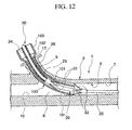
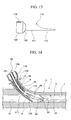
- FIG. 14 when the stent installation member 110 is inserted in this direction, it is inserted so that the blocking part 112 heads upward at the bifurcation 8 so as to block the opening communicating with the second conduit 10.
- the stent installation member 110 In the case that the stent installation member 110 is used, because the flap 33 does not open in the bifurcation 8, the flap 33 is prevented from being bent or the like. And the stent installation member 110 is made so that the blocking part 112 is the extended part of the main body 111, the stent installation member 110 is easy to transform along the conduit and therefore increases workability.
- the transition part 102 By providing the transition part 102, it is possible to regulate the insertion amount of the stent installation member 110 and therefore it is possible to insert the stent 30 without fail.
- the marker 113 on the transition part 102 it is easier to check the position of the blocking part 112 visually and therefore it is possible to position the blocking part 112 at the opening communicating with the second conduit 10 in the bifurcation 8 without fail.
- a stent installation member 120 is provided with a main body 121 which is a tubular blocking part and on a circumferential surface from the distal end to the proximal end of the stent installation member a marker 122, which is an annular identification member, is provided.
- the marker 122 is provided at a position which corresponds to the length from a slot for clamps 12 to the main conduit 7 through the bifurcation 8 and it is provided approximately 60 mm from the distal end of the stent installation member 120 for example.
- the inner diameter, outer diameter and the length of the stent installation member 120 are the same as those of the first embodiment of the present invention.
- the installation member 120 is inserted into the slot for clamps 12 until the marker 122 reaches the slot for clamps 12. At this time, the distal end of the main body 121 reaches the main conduit 7 through the bifurcation 8. And when the stent 30 is guided into the main conduit 7 through the inside of the stent installation member 120, the stent 30 is installed with its flap 33 closed.
- the stent installation member 120 by visually checking the marker 122, it is possible to identify the inserted amount of the stent installation member 120, and the stent installation member 120 can be prevented from being inserted too much into the endoscope 1.
- Other functions and effects of the stent installation member 120 are the same as those of the first embodiment of the present invention.
- An embodiment of the marker 122 may be provided by painting the main body 121 in a different color.
- the distal side and proximal side from the position corresponding to the marker 122 is identified in different colors.
- the treatment instrument insertion channel 5 which is a conduit is provided with a regulative member 130 in the bifurcation 8.
- the regulative member 130 comprises a substantially circular plate-shaped main body 131 connecting with the first conduit 9 and the main body 131 is fixed so that it crosses the bifurcation 8 at a slant toward the main conduit 7 to block a path communicating with the second conduit 10.
- a plurality of slits 132 is provided in parallel on the main body 131. These slits 132 provide communication between the bifurcation 8 and the second conduit 10 and the slit 132 shapes the main body 131 as a grid except for its circumferential portion.
- the guide catheter 25 on which the stent is provided thereon is inserted from the insertion slot 12.
- the stent 30 is inserted into the main conduit 7 from the first conduit 9 through the bifurcation 8 and because the movement of the stent 30 from the bifurcation 8 into the second conduit 10 is regulated by the regulative member 130, the stent 30 is guided into the main conduit 7 so as to be guided by the main body 131 of the regulative member 130. Because the inner diameter of the bifurcation 8, where the first conduit 9 proceeds to the second conduit 10, is kept substantially the same as that of the inner diameter of the first conduit 9, the stent 30 is inserted into the main conduit 7 without the flap 33 of the stent 30 open. On the other hand, when normal saline or the like is supplied from the second conduit, it passes through the slit 132, the bifurcation 8 and the main conduit 7 and is supplied into the human body.
- the regulative member 130 is provided in the treatment instrument insertion channel 5, it is possible to reduce the inner diameter of the conduit when the stent 30 is inserted and because of this the flap 32 of the stent 30 does not open inside the treatment instrument insertion channel 5 and the flap 32 is prevented from being bent or the like. And there is no need to add special structures on the stent delivery catheter side.
- the invention is not limited to the above mentioned embodiments but can be applied broadly.
- the stent installation member may be comprised of only a plate-like member which is extended from the blocking part 112.
- the same function and effect as those of the main body 111 and the blocking part 112 of the stent installation member 110 can be obtained.
- the marker 122 may be provided on the proximal end of the blocking part 112 to be able to check visually the insertion amount of the blocking part 112.
- the first treatment instrument is not limited to the stent delivery catheter but it can be applied to a guide wire provided with a bending at the tip of a sheath already, a papilotomy knife and angiographic catheter.
- the insertion of the stent from the bifurcation 8 into the second conduit 10 is prevented and because of this the stent is prevented from becoming stuck inside of the treatment instrument insertion channel 5, making quick insertion and pulling out of the stent possible.
- the stent delivery catheter is provided with a protective case which houses the stent delivery catheter in a state such that the stent is pulled over around the guide member and the flaps of the stent are open.
- the flaps of the stent are prevented from being bent or the like while the stent delivery catheter is stored.
- the insertion method according to the present invention is comprised of the stent installation member insertion process and the stent insertion process.
- the stent installation member insertion process is utilized when the stent, provided with flaps on the distal end and proximal end of the stent to be placed in human body, is inserted from the insertion slot provided in the divaricated conduit divaricated at the bifurcation from the main conduit of the endoscope which has an opening on its distal end.
- the stent installation member insertion process is to insert the stent installation member from the insertion slot of the divaricated conduit and to make the distal end of the stent installation member pass over the bifurcation and reach the main conduit after inserting the flap of the stent provided on its proximal end inside the stent installation member, which is longer than the route from the insertion slot to the bifurcation of the main conduit, and the stent can be inserted.
- the stent insertion process is to make at least the flap of the stent provided on its proximal end pass over the bifurcation through the stent installation member after the stent installation member insertion process.
- the flap is prevented from opening in the bifurcation by reducing the apparent inner diameter of the conduit in the bifurcation when the stent passes over the bifurcation. As a result, unnecessary forces are not applied to the flap when the stent proceeds into the main conduit from the bifurcation.
- the present invention because it becomes possible to block a part of the bifurcation of the conduit in the endoscope and to reduce the diameter of a part, through which the first treatment instrument passes, it is possible to prevent the first treatment instrument being stuck at the bifurcation or a part of the first treatment instrument being bent. Therefore, it is possible to insert the first treatment instrument without fail.
Landscapes
- Health & Medical Sciences (AREA)
- Engineering & Computer Science (AREA)
- Biomedical Technology (AREA)
- Cardiology (AREA)
- Oral & Maxillofacial Surgery (AREA)
- Transplantation (AREA)
- Heart & Thoracic Surgery (AREA)
- Vascular Medicine (AREA)
- Life Sciences & Earth Sciences (AREA)
- Animal Behavior & Ethology (AREA)
- General Health & Medical Sciences (AREA)
- Public Health (AREA)
- Veterinary Medicine (AREA)
- Media Introduction/Drainage Providing Device (AREA)
- Endoscopes (AREA)
Abstract
Description
- The present invention relates to a treatment instrument installation member, a stent delivery catheter provided with the treatment instrument installation member and a conduit system. Priority is claimed on
Japanese Patent Application No. 2004-277650, filed September 24, 2004 - When stenosis develops at the bile duct or the like inside the human body, it is well known to secure a passage of the bile duct or the like by inserting an elongated tubular stent into the bile duct or the like and further inserting through the stent inside of the stenotic area. At the time of inserting the stent, the stent is provided on an elongated guide member, and a guide member is inserted through a conduit of an endoscope into the inside of the bile duct or the like from the tip of the endoscope and then the stent is pushed out of the guide member. The stent is provided with flaps and by opening these flaps the stent is prevented from being dislodged from the stenosis area.
- Conventionally, at the time of inserting the stent, a stent installation member to guide the stent into the conduit of endoscope has been used. The stent installation member has substantially the same inner diameter as the opening of the insertion slot of the conduit and the stent installation member is made so that the stent provided inside of the stent installation member is guided into the conduit if the stent installation member is pressed against the surroundings of the insertion slot of the conduit.
- Because the flap provided on the proximal side of the stent is made to open towards the distal end of the stent, it is possible for the flap on the proximal side to bent due to interference with the insertion slot of the conduit at the time of inserting the stent. Because of this, an invention such as
Patent Document 1 is disclosed that enables the tip of the stent installation member to be inserted into the insertion slot of the conduit. The stent installation member has a length to completely cover the flap provided on the proximal side of the stent and therefore the flap on the proximal side is kept covered by the stent installation member and inserted into the insertion slot of the conduit.
Patent Document 1:Japanese Unexamined Patent Application, First Publication No. H11-76412 - However, the conduit of the endoscope is divaricated into branches to perform insufflations or the like and the diameter of the conduit is larger at the bifurcation, and therefore, when the stent is passing through the bifurcation, the flaps may open because the diameter of the conduit is larger there. If the flap opens at the bifurcation, it may be bent when the flap is further inserted into the conduit which has a diameter smaller than that of the bifurcation. Therefore, even if the flaps are protected at the time of insertion at the insertion slot of the conduit, if the conduit has an area with a larger diameter than that of the insertion slot, the flap may be bent or the like. A bent flap as mentioned above tends to be caught by a support pillar provided at the distal end of the endoscope making it difficult to push the stent out of the endoscope. Apart from the case using the stent, in the case of using a guide wire, papilotomy knife or angiographic catheter, it is known that if there is bending at the tip of a sheath, it is easy to become caught at the bifurcation. This invention was made considering the above-mentioned situations and its purpose is to be able to place the stent within the human body without fail.
- According to a first embodiment of the present invention, a treatment instrument installation member is provided which is used when the first treatment instrument is inserted into the first conduit of the conduit system that includes the first conduit provided with an inner diameter through which the first treatment instrument can be inserted and the second conduit provided with an inner diameter through which the second treatment instrument can be inserted, and the main conduit provided with an inner diameter through which the first and the second treatment instrument can be inserted and a connection part that connects the first conduit, second conduit and the main conduit together. The treatment instrument insertion member is comprised of a main body which has an outer diameter that can be inserted into the first conduit and a distal end part located on the distal end of the main body that has a blocking part which blocks at least a part of the opening through which the second conduit communicates to the connection part.
- According to the treatment instrument installation member of the present invention, the diameter of the first conduit through which the first treatment instrument is inserted decreases because if the main body is inserted into the first conduit, the distal end of the main body blocks a part of the opening at the connection part.
- Preferably, the main body of the above mentioned treatment instrument installation member is a tubular member which has an outer diameter smaller than the inner diameter of the first conduit and that of the connection part and is provided with an inner diameter larger than that of the outer diameter of the first treatment instrument, and the distal end portion is exposed from the conduit system at the insertion slot which is provided on a side where the operating area for the conduit system is provided while the distal end part blocking at least a part of the opening communicating with the second conduit at the connection part.
- According to this installation member of the present invention, a conduit which has a smaller inner diameter than that of the connection part is created by the main body through which the first treatment instrument is inserted.
- Preferably, the main body of the above mentioned treatment instrument installation member is provided with a regulative part on its proximal end which regulates the installation amount of the main body into the first conduit.
- According to this installation member of the present invention, an insertion into the correct location can be achieved by the installation amount being regulated by the regulative part.
- Preferably, a stent delivery catheter is provided that is used with an endoscope including the first conduit provided with an inner diameter through which the first treatment instrument can be inserted, the second conduit provided with an inner diameter through which the second treatment instrument can be inserted, the main conduit provided with an inner diameter through which the first and the second treatment instrument can be inserted and a connection part that connects the first conduit, second conduit and the main conduit together. The stent delivery catheter comprises a guide member inserted into the first conduit and the main conduit from the insertion slot for the first treatment instrument provided at the operation area of the endoscope, a stent which is movable forward and backward which is provided on the guide member, a pushing member which is movable forward and backward which is provided on the guide member to push the stent out of the guide member to be placed in the human body, and a stent installation member which corresponds the above-mentioned treatment instrument installation member which is movable forward and backward which is provided on the pushing member and on the stent.
- According to the stent delivery catheter of the present invention, the insertion of the stent can be performed with a part of the opening of the connection part blocked by the stent installation member, and therefore the bending of the flap of the stent, which is caused by the opening of the flap, is prevented when the stent is passing through the connection part.
- Preferably, the stent of the above mentioned stent delivery catheter is provided with flaps which regulate the movement of the stent, and the stent delivery catheter is provided with a protective case which covers the stent with its flaps open and with the stent provided on the guide member.
- According to the stent delivery catheter of the present invention, flaps of the stent are prevented from being bent during storage by being provided with a protection case.
- Preferably, an endoscope treatment system provided with the endoscope and the stent delivery catheter is provided.
- According to the endoscope treatment system of the present invention, the stent can be inserted in the correct condition because the flap of the stent is prevented from being bent at the connection part when the stent is inserted into the human body.
- Preferably, a conduit system is provided which comprises the first conduit which is provided with an inner diameter through which the treatment instrument can be inserted, the second conduit which is provided with an inner diameter through which the second treatment instrument can be inserted, the main conduit which is provided with an inner diameter through which the first and the second treatment instrument can be inserted, a connection part which connects the first conduit, second conduit and the main conduit together, and a regulative member which is provided at the connection part and prevents the first treatment instrument inserted from the first conduit from proceeding into the second conduit and at the same time enables the second treatment instrument inserted from the second conduit to proceed into the main conduit.
- Preferably, a stent installation method is provided which is utilized when the stent, which has flaps on its distal end and proximal end each to be placed in the human body, is inserted from the insertion slot provided on the divaricated conduit divaricated at the bifurcation from the main conduit of the endoscope which has an opening on its distal end. The stent installation method includes a stent installation member insertion process and stent insertion process. The stent installation member insertion process is to insert the stent installation member, through which the stent can be inserted and which is longer than the route from the insertion slot to the bifurcation of the main conduit, from the insertion slot of the divaricated conduit and to enable the distal end of the stent installation member to pass through the bifurcation and to reach the main conduit after placing at least the flap of the stent provided on the proximal end of the stent inside of the stent installation member. The stent insertion process is to make at least the flap of the stent provided on its proximal end pass through the bifurcation by passing through the stent installation member after the stent installation member insertion process.
- According to the stent installation method, because the stent installation member insertion process is provided, the flap of the stent is prevented from opening at the bifurcation by reducing the apparent diameter of the conduit at the bifurcation when the stent is passing through the bifurcation. As a result, unnecessary force is not applied on the flap when the stent is proceeding to the main conduit from the bifurcation.
-
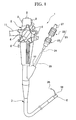
- FIG 1 is an overall view of an endoscope treatment system including a stent delivery catheter according to an embodiment of the present invention.
- FIG. 2 is a cross section of a partially enlarged side view of the endoscope treatment system of FIG. 1.
- FIG. 3 is an overall view showing a structure of the stent delivery catheter.
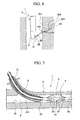
- FIG. 4 is a view explaining a usage of the stent delivery catheter.
- FIG. 5 is a cross section of a partially enlarged side view of the endoscope treatment system of FIG. 1, showing a stent inserted into a main conduit.
- FIG. 6 is a view showing the stent inserted into a living body.
- FIG. 7 is a view showing the stent.
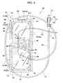
- FIG. 8 is a view showing the stent delivery catheter and its protective case.
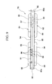
- FIG. 9 is a side view of the protective case.
- FIG. 10 is a side view of the stent installation member.
- FIG. 11 is a view showing the installation of the stent.
- FIG. 12 is a side view showing the stent installation member inserted into the endoscope.
- FIG. 13 is a side view of the stent installation member.
- FIG. 14 is a side view showing the stent installation member inserted into the endoscope.
- FIG. 15 is a side view of the stent installation member.
- FIG. 16 is a side view showing the stent installation member inserted into the endoscope.
- FIG. 17 is a view of a regulative member seen from the conduit B-B toward the direction of the arrow in FIG. 16.
- The best mode for carrying out the invention of the present application is explained by referring to the drawings.
- FIG. 1 is a view showing a stent delivery catheter according to a first embodiment of the present invention inserted through an endoscope and FIG. 2 is an enlarged view of the cross section of part A of FIG. 1.
- As shown in FIGS. 1 and 2, an
endoscope 1 has anendoscope operation part 2 that an operator operates and, on the tip of theendoscope operation part 2, anendoscope insertion part 3 is provided to be inserted into the human body. Theendoscope insertion part 3 is flexible and can be bent by aknob 4 of theendoscope operation part 2. A treatmentinstrument insertion channel 5, which is a conduit system, is provided inside of theendoscope 1. Adistal end 6 of the treatmentinstrument insertion channel 5 has an opening on the side of thedistal end 6 of theendoscope insertion part 3 and communicates with theendoscope operation part 2 through theendoscope insertion part 3. - The treatment
instrument insertion channel 5 comprises amain conduit 7 which communicates with thedistal end 6 of theendoscope insertion part 3 and afirst conduit 9, and is divaricated to asecond conduit 10 at abifurcation 8 which is a connection part. Thesecond conduit 10 extends along the axis of themain conduit 7 and communicates with a liquid supply conduit and air supply conduit which are both not shown, and can supply normal saline as a second treatment instrument. The liquid supply conduit or the air supply conduit are communicate with a liquid supply apparatus or an air supply apparatus provided outside via auniversal cord 11 which extends from the side of theendoscope operation part 2 as shown in FIG. 1. Thefirst conduit 9 is extended to aninsertion slot 12 provided on the side of theendoscope operation part 2. Astent delivery catheter 20 is inserted as the first treatment instrument into theinsertion slot 12. - As shown in FIGS. 1 and 3, the
stent delivery catheter 20 has anoperation part 21 with which an operator operates. Anoperation part 21 comprises amouth ring 22 for a guide catheter and amouth ring 23 for a pusher tube which is removably provided on themouth ring 22 for a guide catheter. Themouth ring 23 for a pusher tube is provided with apusher tube 24 on the distal end of themouth ring 23 for a pusher tube. Thepusher tube 24 comprises a flexible elongated tubular member. Aguide catheter 25, which is a guide member, is movably inserted forward and backward through thepusher tube 24. Theguide catheter 25 comprises a flexible member and is provided with lumens and amarker 26 for X-ray imaging which is buried on the distal end of theguide catheter 25. The lumens, which is passing through inside of themouth ring 23 for a pusher tube, and communicate with aconnection part 27 provided on the proximal end of themouth ring 22 for a guide catheter. Theconnection part 27 comprises a luer-lock or the like and can communicate with syringes or the like which are not shown in figures. - The
guide catheter 25 is longer than thepusher tube 24 and the distal end of theguide catheter 25 is exposed from the distal end of thepusher tube 24 when themouth ring 22 for a guide catheter and themouth ring 23 for a pusher tube are connected. Astent 30 is movably provided forward and backward around the exposingdistal end 25a. - The
stent 30 is provided with a tubularmain stent body 31. The inner diameter of amain stent body 31 is substantially the same as the outer diameter of theguide catheter 25. The outer diameter of themain stent body 31 is smaller than the inner diameters of those of themain conduit 7 or thebifurcation 8 or thefirst conduit 9. Aflap 32 is provided on the distal end of thestent 30. Fourflaps 32 are provided on the circumference of the stentmain body 31 and each of the flaps has a 90-degree interval with adjacent flaps, and when a pressure is not applied they are made to open toward the proximal end of thestent 30 by lifting the tip of the flap which is closer to the proximal end. And when a prescribed pressure is applied they are capable of changing their shapes to close themselves. Each of the fourflaps 32 is made so as to gradually reduce its width from the proximal end, which is connected to themain stent body 31, to its distal end. Fourflaps 33 are provided on the proximal end of thestent 30. Theflaps 33 have the same structure as theflaps 32 except that when a pressure is not applied they are made to open toward the distal end of thestent 30 by lifting the four tips of the flap closer to the distal end. - Further, a
stent installation member 35 is movably provided forward and backward around thepusher tube 24. Thestent installation member 35 comprises a tubularmain body 35a and the inner diameter of the tubularmain body 35a is larger than the outer diameter of thepusher tube 24. The inner diameter of thestent installation member 35 is larger than the outer diameter of thestent 30 in a state where both theflaps stent installation member 35 is smaller than the inner diameter of thefirst conduit 9 which is located closer to theendoscope 1 and the inner diameter of thebifurcation 8. As explained in detail later, the length of thestent installation member 35 is longer than the total length of thefirst conduit 9 and is shorter than thepusher tube 24 and more preferably, it is approximately 90 mm. - The
stent installation member 35 as described above is made of fluorine resin (including PTFE, PFT, FEP or the like) or polyethylene resin or the like. The reason for this is because thestent installation member 35 should be thin, rigid and smooth enough to enable the insertion of thestent installation member 35 into thefirst conduit 9. And in thestent installation member 35, at least adistal end 35b thereof may be made to be deformable. A structure which enables thedistal end 35b of thestent installation member 35 to be deformable is achieved by making, for example, the wholestent installation member 35 or thedistal end 35b of thestent installation member 35 with a flexible material or to make thedistal end 35b of thestent installation member 35 thinner than other parts or to provide slits on thedistal end 35b of thestent installation member 35 along the longitudinal direction or the like. This kind ofdistal end 35b of thestent installation member 35 acts as a blocking member by reducing the area through which thestent 30 passes at thebifurcation 8. - Next, the operation of this embodiment of present invention is explained. The explanation is made referring to an example shown in FIG. 4 which shows a case where the
stent 30 is inserted into a bile duct W3 from a duodenal papilla W2 of the duodenum W1 of the patient. In FIG. 4, aguide wire 50 is inserted into the bile duct W3. Theguide wire 50 is pre-inserted from the duodenal papilla W2 by using an angiographic tube or the like which is not shown in figures. And when the angiographic tube is pulled out, the distal end of theguide wire 50 remains inside of the bile duct W3 and at the same time the proximal end of theguide wire 50 is pulled outside the body passing through the treatmentinstrument insertion channel 5 of theendoscope 1. - In the case of inserting the
stent 30 as shown in FIG. 3, themouth ring 22 for a guide catheter and themouth ring 23 for a pusher tube are connected first and then thepusher tube 24 and theguide catheter 25 are connected via theoperation part 21. And then thestent installation member 35 is slid toward the distal end of theguide catheter 25 and theflap 33 provided on the proximal end of thestent 30 is covered with thestent installation member 35. - Next, the proximal end of the
guide wire 50 is inserted into the lumen from the distal end of theguide catheter 25 and pulled out from theconnection part 27 of themouth ring 22 for a guide catheter of theoperation part 21 and then theguide catheter 25 is inserted into thefirst conduit 9 from theinsertion slot 12 of theendoscope 1. Because the outer diameter of theguide catheter 25 is much smaller than the inner diameter of thefirst conduit 9 and thebifurcation 8, theguide catheter 25 is bent at thebifurcation 8 and led along themain conduit 7 and directed toward the distal end of themain conduit 7. As theguide catheter 25 is directed, thestent 30 and thestent installation member 35 which is provided around the proximal end of thestent 30 are also inserted into thefirst conduit 9. (Stent installation member insertion process) - The
stent 30 is inserted into thefirst conduit 9 while theflap 32 provided on the distall end of thestent 30 is closed. And thestent 30 is bent along theguide catheter 25 at thebifurcation 8 when thestent 30 proceeds from thefirst conduit 9 into themain conduit 7. Because the apparent inner diameter is increased at thebifurcation 8, eachflap 32 opens temporarily at thebifurcation 8 and closes again when the stent is inserted into themain conduit 7. Because theflaps 32 are made to open by lifting the four tips of the flap closer to the proximal end of thestent 30, theflaps 32 are inserted into themain conduit 7 without being bent as shown in FIG. 2. - The
stent installation member 35, which is inserted into thebifurcation 8 following the distal end of thestent 30, is inserted into themain conduit 7 with the distal end of thestent installation member 35 being bent at thebifurcation 8. However, thestent installation member 35, which has substantially the same outer diameter as the inner diameter of thefirst conduit 9 and has rigidity as a whole, stops as if it fits into thefirst conduit 9 and themain conduit 7. In this state, by further inserting theguide catheter 25 into the treatmentinstrument insertion channel 5, thestent installation member 35 remains stationary and thestent 30 moves forward as it is pushed by thepusher tube 24. As a result, as shown in FIG. 5, the proximal end of thestent 30 is pushed out of the distal end of thestent installation member 35. Because theflaps 33 are pushed out of thestent installation member 35 after passing through thebifurcation 8, which has an increased inner diameter, even if theflap 33 opens inside of themain conduit 7, theflap 33 is not bent. - And if the
guide catheter 25 reaches the distal end of theendoscope 1, as shown in FIG. 4, the position of the distal end of theguide catheter 25 is adjusted to the position of the duodenal papilla W2 by raising asupport pillar 51 of thedistal end 6 of theendoscope 1. When the positioning is completed, theguide catheter 25 is further pushed and its distal end is inserted inside of the bile duct W3. (Stent installation process) - When the
marker 26 is inserted so much that it passes over a stenosis W4, theguide catheter 25 is fixed and the mouth rings 22 for a guide catheter, 23 for a pusher tube of theoperation part 21 are separated each other and thepusher tube 24 is moved forward along theguide catheter 25. When thepusher tube 24 moves forward, the distal end of thepusher tube 24 pushes thestent 30 toward the distal end of theguide catheter 25. Because of this, as shown in FIG. 6, the distal end of thestent 30 is passed through the duodenal papilla W2 and inserted into the bile duct W3 and is located in an area deeper than the stenosis W4. As theflaps 32 are open toward the proximal end of the stent at this time, they are closed when they pass through the duodenal papilla W2, however, they open again in the area deeper than the stenosis W4 inside of the bile duct W3. Theflaps 33 open toward the distal end of thestent 30 inside of the duodenum W1. And when theguide catheter 25 is pulled out in a state that thepusher tube 24 is fixed relative to theendoscope 1, then thestent 30 is installed. As a result, the bile duct W3 and theduodenum W 1 communicate through a through-hole provided inside of the stentmain body 31. A movement toward the bile duct W3 is regulated by theflap 33 and the movement of thestent 30 toward the duodenum W1 is regulated by theflap 32. - According to this embodiment of the present invention, since the
stent installation member 35 is inserted into the treatmentinstrument insertion channel 5 and the distal end of thestent installation member 35 reaches beyond thebifurcation 8 to themain conduit 7, it is possible to reduce the inner diameter of the space where thestent 30 passes through in the vicinity of thebifurcation 8 and theflaps 33 of thestent 30 are prevented from being open in thebifurcation 8. If thestent installation member 35 is not provided, when the stent proceeds from thebifurcation 8 into themain conduit 7, theflaps 33 which open toward the distal end of thestent 30 tend to be bent because the inner diameter is reduced, however, in this embodiment of the present invention this problem is prevented. Therefore, during the insertion of thestent 30, the bent flap is prevented from getting stuck by thesupport pillar 51. Furthermore, when thestent 30 is placed in the human body, thestent 30 is not easily dislodged because of the correct functions of theflaps stent installation member 35 has such a rigidity to be inserted into thefirst conduit 9 and the distal end of thestent installation member 35 is made to change its shape along thebifurcation 8 and themain conduit 7, deformation or the like of theflaps 33 are prevented by simply inserting thestent installation member 35 into theendoscope 1 until it stops. - Furthermore, because the
stent 30 and thestent installation member 35 are preliminarily provided around theguide catheter 25 andpusher tube 24, thestent delivery catheter 20 contributes to reducing the burden of placing thestent 30 during surgery and lessening the surgery time. - The stent used as one of the embodiments of the present invention can be as follows.
- As shown in FIG. 7, a
stent 60 comprises amain body 61 which is a tubular blocking part provided with a through-hole. The circumference of adistal end 61a of themain body 61 is tapered so as to reduce the outer diameter of thedistal end 61 a of themain body 61 toward its distal end. On the more proximal side than the chamfering part of thedistal end 61a of themain body 61, alateral hole 62 is provided which has an opening on the lateral face of themain body 61 which connects with the through-hole of themain body 61 in a perpendicular direction. On the more proximal side than thelateral hole 62, aflap 63 is provided. Theflap 63 is made so that a part of themain body 61 is peeled from the proximal end to the distal end of thestent 60 by lifting the distal end of the flap and the width of theflap 63 is reduced toward its distal end from the proximal end which is connected to themain body 61, and theflap 63 is made so as to be able to change shape by a force applied from outside. On the proximal end of themain body 61, aflap 64 is provided and its structure is the same as that of theflap 63 except that the distal end of theflap 64 is lifted toward the distal end of themain body 61. - The
stent 60 has a shorter distance from its distal end and to theflap 63 than the conventional stents and further has a shorter distance from its proximal end to theflap 64 than the conventional stents. By keeping the distance on the distal end of the main body shorter, the interference between the surface of the lumens like the bile duct W3 or the like and the distal end of thestent 60 is minimized. And by keeping the distance on the proximal end of the main stent body shorter, disruption of the flow of food or the like inside of the duodenum W1 is reduced because it keeps the amount of projection of the proximal end of thestent 60 out to the duodenum W1 small when the proximal end of thestent 60 is disposed inside of the duodenum W1 for example. Considering the insertion of thestent 60 into the bile duct W3 as above for example, preferably, the distance between thedistal end 61 a of thestent 60 to theflap 63 is 20 mm and the distance between the proximal end of thestent 60 to theflap 64 is 12 mm. - Because the
distal end 61 a of thestent 60 is tapered, it is possible to smoothly insert it into the duodenal papilla W2 or the like thereby reducing discomfort to the patient. Because the distal side of thestent 60 which is inserted into the bile duct W3 or the like is made longer than the conventional stents, damage or the like to the mucous membrane on the tube wall is reduced because the distal end 60a of thestent 60 does not easily become stuck in the wall surface. Furthermore, because the proximal end of thestent 60 is shorter, the flow of food or the like is kept smoother and an uncomfortable feeling in the patient is reduced. As with the previous embodiment of the stent, it is preferable to provide thestent 60 around theguide catheter 25 preliminarily. As a result, it is possible to avoid setting the direction of thestent 60 reversely which has a tapereddistal end 61 a or has a different length on the distal side 60a and the proximal side. - Furthermore, this embodiment of the present invention may be placed in the following case.
- As shown in FIG. 8, a
stent delivery catheter 65 is provided with aprotective case 70. In this embodiment of the present invention, astent 71 is provided around theguide catheter 25. Thestent 71 comprises a bentmain body 72 and fourflaps 73 which are provided around the distal end of themain body 72 at equal intervals in the circumferential direction. Each of theflaps 73 is curved so that it opens toward the proximal end of the stent. In a similar way, on the proximal side, fourflaps 74 are provided at equal intervals in the circumferential direction and each of theflaps 74 is curved so that it opens toward the distal end of the stent. This kind ofstent 71 is used in a case, for example, to promote the expulsion of bile in the stenotic area when a stenosis developes in a bile duct. - As shown in FIG.S. 8 and 9, the
protective case 70 is constructed so that abasement 80 and alid 81 are connected via aconnection part 82 and when overlapping thebasement 80 with thelid 81 by bending theconnection part 82, it is possible to house thestent 71, a part of theguide catheter 25 and a part of thepusher tube 24 in the space created thereinside. - As shown in FIG. 9, the
basement 80 comprises ahousing part 84, except aflange 83 which is the surroundings of thebasement 80, and arib 85 which keeps the strength provided on substantially the center in the longitudinal direction on thebasement 80. As shown in FIG. 8, therib 85 is provided with a plurality ofgrooves 86 along the longitudinal direction of therib 85 which is also the direction of the narrow side of thebasement 80. Thesegrooves 86 are made to removably hold the straight-conduit portion of thestent 71 and the shapes of the grooves are adjusted to the diameter or the shape of thestent 71. Theflange 83 is provided with a plurality ofconvexes 87 which fit together with thelid 81 on the four corners. - On one lateral side of the longitudinal direction of the
basement 80, aslit 90 is provided through which theguide catheter 25 passes. The width of theslit 90 is much bigger than the outer diameter of theguide catheter 25. On theflange 83 of thebasement 80, theconnection part 82 is provided on onefringe 83a which is in the direction of narrow side of thebasement 80 and thebasement 80 and thelid 81 is formed integrally via theconnection part 82. On anotherfringe 83b, atongue 92 is provided on the extension of thefringe 83b which is to be held with aflange 91 of thelid 81. - The
lid 81 is comprised of ahousing part 93, except for theflange 91 which is in the surroundings of thebasement 81, and arib 94 on substantially the center in the longitudinal direction on thelid 81. Therib 94 is provided with a plurality ofgrooves 95 which are made to removably hold the straight-conduit portion of thestent 71 along the longitudinal direction of therib 94. Thesegrooves 95 are made in a bent shape to hold the bent portion of thestent 71. Theflange 91, which is overlapped with theflange 83 of thebasement 80, is provided with a plurality ofconcaves 96 on the four corners which fit together with theconvexes 87 of theflange 83. - Furthermore, on one lateral side of the longitudinal direction of the
lid 81, aslit 97 is provided through which theguide catheter 25 passes. Theslit 97 is formed on a position which overlaps with theslit 90 and formed in the same shape as theslit 90 and theslit 97 creates a space with theslit 90 through which theguide catheter 25 is inserted. A plurality ofslits 98 are provided in a symmetrical position against theslit 90 across therib 94 on one lateral side of thelid 81. Each slit 98, which is to be inserted through by the correctly positionedpusher tube 24, has a width substantially the same as the outer diameter of thepusher tube 24 and a plurality of theslits 98 are provided on thelid 81 along its longitudinal direction. Each slit 98 is slanted off in the longitudinal direction of thelid 81. In order to prevent thepusher tube 24 from deviating, a plurality ofswells 99 is provided at a location symmetrical against each of theslits 98. As shown in FIG. 8, on theflange 91 of thelid 81, anengagement 91 a is provided to hold thetongue 92. - This
stent delivery catheter 65 which is covered by theprotective case 70 is stored in a sterile pack. The height of thehousing parts protective case 70 is much higher than the projected amount of theflap housing part flap stent 71 is kept open without being interfered with by the wall of theprotective case 70 and their deformation is restrained. And the deviation of thestent 71 is also restrained because it is held by thegroove 86. - When the
stent delivery catheter 20 is used, it is taken out of the sterile pack and then theprotective case 70 is opened to remove thepusher tube 24 out of theslit 98 and pick up thestent 71 out of thegroove 86. Subsequent method of usage is the same as that of the first embodiment of the present invention. - As described above, because it is possible to store and use the
stent delivery catheter 65 as one integrated unit, handling thereof becomes easy. And because thestent 71 is held by theprotective case 70, deformation or the like of theflap - Furthermore, by providing the
slit 98 on theprotective case 70, it is possible to hold thepusher tube 24 in a fixed state and this protects thestent 71 from being subjected to unexpected stresses. Because theguide catheter 25 passes through thewide slit stent 71 is held by any of thegrooves 86, unexpected forces are not applied to theguide catheter 25. - When the
stent 71 is held by thegroove 95 on thelid 81, theguide catheter 25 and thepusher tube 24 are inserted through theslits stent delivery catheter 65 shown in FIG. 8. And thestent installation member 35 may be held by either of thegroove 86 or thegroove 95. - Next, the second embodiment of the present invention is explained by referring to the figures. The same symbols are provided for the structural members common to the first embodiment of the present invention. Explanation is omitted of the structural members already explained above.
- As shown in FIG. 10, a
stent installation member 100 comprises a tubularmain body 101 which functions as a blocking part and atapered transition part 102 which functions as a regulative part on the proximal side of themain body 101. The outer diameter of aproximal end part 103 of thestent installation member 100 is larger than that of themain body 101 due to thetransition part 102. Themain body 101,transition part 102 and theproximal end part 103 of thestent installation member 100 are integrally formed and they are shaped in a hollow tubular shape. Themain body 101 is the blocking part provided with an outer diameter so that it can be inserted into thefirst conduit 9 and further into thebifurcation 7 from theinsertion slot 12. The inner diameter of themain body 101 is made so that thestent 30 can be inserted in a state such that theflaps main body 101 is longer than the route from theinsertion slot 12 to thebifurcation 8 and is shorter than thepusher tube 24 and is preferably, for example, 60 mm. And theproximal end part 103 is provided with an outer diameter larger than theinsertion slot 12 and is provided with an inner diameter so that thestent 30 can be inserted. Thetransition part 102 is made, for example, by thermoforming a tube, by covering a heat-shrinkable tube so as to have a step, or by connecting different tubes with different outer diameters. - The function of the
stent installation member 100 will be explained. - As shown in FIG. 11, the distal end of the
guide catheter 25 and the distal end of thestent 30 are inserted into the treatmentinstrument insertion channel 5 from theinsertion slot 12 of theendoscope 1. Before theflap 33 on the proximal side of thestent 30 is inserted from theinsertion slot 12, thestent installation member 100 is inserted from theinsertion slot 12. As shown in FIG. 12, thestent installation member 100 is inserted until thetransition part 102 reaches theinsertion slot 12. At this time, the distal end of themain body 101 reaches into themain conduit 7 passing through thefirst conduit 9 and thebifurcation 8. In this state, when thestent 30 is further inserted, theflap 33 on the proximal side of thestent 30 is covered inside of thestent installation member 100 and the stent reaches themain conduit 7 through thebifurcation 8. - In this manner, when the
stent installation member 100 is used, by thetransition part 102 being caught by theinsertion slot 12, the insertion amount of thestent installation member 100 is regulated so as to be most suitable for the installation of thestent 30, accordingly, thestent installation member 100 is prevented from being inserted more than necessary into theendoscope 1. Other functions and effects are the same as those of the first embodiment of the present invention as described above. - In this embodiment of the present invention, the following stent installation member can be also used.
- As shown in FIG. 13, a
stent installation member 110 comprises a tubularmain body 111 and aproximal part 103 provided on the proximal end of themain body 111 which has a larger diameter by being connected to thetransition part 102. On the extension of the distal end of themain body 111, a blockingmember 112 is provided. The blockingmember 112 comprises a part of the circumference of themain body 111 extending along the axis of the main body. The inner diameter of themain body 111 is made so that it can house thestent 30 in a state such that theflaps main body 111 is smaller than the diameter of thefirst conduit 9. The length of themain body 111 is shorter than the total length of thefirst conduit 9, however, as a wholestent installation member 110, it is long enough to reach themain conduit 7 through thebifurcation 8 from theinsertion slot 12. The length of themain body 111 is preferably, for example, approximately 30 mm and the length of the blockingpart 112 in this case is approximately 30 mm. - A
marker 113 is provided on thetransition part 102 of thestent installation member 100 so that the position where the blockingpart 112 is extended can be identified in the circumferential direction. Themarker 113 is provided at a position shifted by 180 degrees in the circumferential direction from the extended part of the blockingpart 112. In other words, on the stent installation member 110 a part of which is slit in the circumferential direction, amarker 113 is provided on a corresponding part of thestent installation member 110 which is slit. - The
stent installation member 110 is inserted into theinsertion slot 12 when thestent 30 is inserted. Thestent installation member 110 is inserted so that themarker 113 of thetransition part 102 is directed to theinsertion part 3 of the endoscope, that is, to the downside in FIG. 1, and the stent installation member is inserted until thetransition part 102 contacts theinsertion slot 12. As shown in FIG. 14, when thestent installation member 110 is inserted in this direction, it is inserted so that the blockingpart 112 heads upward at thebifurcation 8 so as to block the opening communicating with thesecond conduit 10. When thestent 30 is sent toward themain conduit 7, in this state, one piece of theflap 33 which is provided on the proximal side of thestent 30 and facing the opening communicating with thesecond conduit 10 maintains contact with the blockingpart 112 and is guided into themain conduit 7. As a result, theflap 33 does not open in thebifurcation 8 and is guided into themain conduit 7. - In the case that the
stent installation member 110 is used, because theflap 33 does not open in thebifurcation 8, theflap 33 is prevented from being bent or the like. And thestent installation member 110 is made so that the blockingpart 112 is the extended part of themain body 111, thestent installation member 110 is easy to transform along the conduit and therefore increases workability. By providing thetransition part 102, it is possible to regulate the insertion amount of thestent installation member 110 and therefore it is possible to insert thestent 30 without fail. In this case, by providing themarker 113 on thetransition part 102, it is easier to check the position of the blockingpart 112 visually and therefore it is possible to position the blockingpart 112 at the opening communicating with thesecond conduit 10 in thebifurcation 8 without fail. - Next, a third embodiment of the present invention is explained referring to the figures. The same symbols are provided for the structural members which are common to the above-described embodiment of the present invention. Explanation is omitted of the structural members already explained above.
- As shown in FIG. 15, a
stent installation member 120 is provided with amain body 121 which is a tubular blocking part and on a circumferential surface from the distal end to the proximal end of the stent installation member amarker 122, which is an annular identification member, is provided. Themarker 122 is provided at a position which corresponds to the length from a slot forclamps 12 to themain conduit 7 through thebifurcation 8 and it is provided approximately 60 mm from the distal end of thestent installation member 120 for example. The inner diameter, outer diameter and the length of thestent installation member 120 are the same as those of the first embodiment of the present invention. - A function of the
stent installation member 120 will be explained. - The
installation member 120 is inserted into the slot forclamps 12 until themarker 122 reaches the slot forclamps 12. At this time, the distal end of themain body 121 reaches themain conduit 7 through thebifurcation 8. And when thestent 30 is guided into themain conduit 7 through the inside of thestent installation member 120, thestent 30 is installed with itsflap 33 closed. - According to the
stent installation member 120, by visually checking themarker 122, it is possible to identify the inserted amount of thestent installation member 120, and thestent installation member 120 can be prevented from being inserted too much into theendoscope 1. Other functions and effects of thestent installation member 120 are the same as those of the first embodiment of the present invention. - An embodiment of the
marker 122 may be provided by painting themain body 121 in a different color. In particular, the distal side and proximal side from the position corresponding to themarker 122 is identified in different colors. - Next, a fourth embodiment of the present invention is explained referring to the figures. The same symbols are provided for the structural members which are common to the above-described embodiment of the present invention. Explanation is omitted of the structural members already explained above.
- As shown in FIG. 16, the treatment
instrument insertion channel 5 which is a conduit is provided with aregulative member 130 in thebifurcation 8. Theregulative member 130 comprises a substantially circular plate-shapedmain body 131 connecting with thefirst conduit 9 and themain body 131 is fixed so that it crosses thebifurcation 8 at a slant toward themain conduit 7 to block a path communicating with thesecond conduit 10. Furthermore, as shown in FIG 17, a plurality ofslits 132 is provided in parallel on themain body 131. Theseslits 132 provide communication between thebifurcation 8 and thesecond conduit 10 and theslit 132 shapes themain body 131 as a grid except for its circumferential portion. - When the
stent 30 is inserted by using the treatmentinstrument insertion channel 5, theguide catheter 25 on which the stent is provided thereon is inserted from theinsertion slot 12. Thestent 30 is inserted into themain conduit 7 from thefirst conduit 9 through thebifurcation 8 and because the movement of thestent 30 from thebifurcation 8 into thesecond conduit 10 is regulated by theregulative member 130, thestent 30 is guided into themain conduit 7 so as to be guided by themain body 131 of theregulative member 130. Because the inner diameter of thebifurcation 8, where thefirst conduit 9 proceeds to thesecond conduit 10, is kept substantially the same as that of the inner diameter of thefirst conduit 9, thestent 30 is inserted into themain conduit 7 without theflap 33 of thestent 30 open. On the other hand, when normal saline or the like is supplied from the second conduit, it passes through theslit 132, thebifurcation 8 and themain conduit 7 and is supplied into the human body. - According to the embodiment of the present invention, because the
regulative member 130 is provided in the treatmentinstrument insertion channel 5, it is possible to reduce the inner diameter of the conduit when thestent 30 is inserted and because of this theflap 32 of thestent 30 does not open inside the treatmentinstrument insertion channel 5 and theflap 32 is prevented from being bent or the like. And there is no need to add special structures on the stent delivery catheter side. - The invention is not limited to the above mentioned embodiments but can be applied broadly.
- For example, the stent installation member may be comprised of only a plate-like member which is extended from the blocking
part 112. By using this kind of stent installation member, the same function and effect as those of themain body 111 and the blockingpart 112 of thestent installation member 110 can be obtained. In this state, themarker 122 may be provided on the proximal end of the blockingpart 112 to be able to check visually the insertion amount of the blockingpart 112. - The first treatment instrument is not limited to the stent delivery catheter but it can be applied to a guide wire provided with a bending at the tip of a sheath already, a papilotomy knife and angiographic catheter. In the case of using this kind of treatment instrument, the insertion of the stent from the
bifurcation 8 into thesecond conduit 10 is prevented and because of this the stent is prevented from becoming stuck inside of the treatmentinstrument insertion channel 5, making quick insertion and pulling out of the stent possible. - Further, according to another embodiment of the present invention, the stent delivery catheter is provided with a protective case which houses the stent delivery catheter in a state such that the stent is pulled over around the guide member and the flaps of the stent are open.
- Because the stent delivery catheter is provided with the protective case, the flaps of the stent are prevented from being bent or the like while the stent delivery catheter is stored.
- The insertion method according to the present invention is comprised of the stent installation member insertion process and the stent insertion process. The stent installation member insertion process is utilized when the stent, provided with flaps on the distal end and proximal end of the stent to be placed in human body, is inserted from the insertion slot provided in the divaricated conduit divaricated at the bifurcation from the main conduit of the endoscope which has an opening on its distal end. The stent installation member insertion process is to insert the stent installation member from the insertion slot of the divaricated conduit and to make the distal end of the stent installation member pass over the bifurcation and reach the main conduit after inserting the flap of the stent provided on its proximal end inside the stent installation member, which is longer than the route from the insertion slot to the bifurcation of the main conduit, and the stent can be inserted. The stent insertion process is to make at least the flap of the stent provided on its proximal end pass over the bifurcation through the stent installation member after the stent installation member insertion process.
- According to the stent installation method, because the stent installation member insertion process is provided, the flap is prevented from opening in the bifurcation by reducing the apparent inner diameter of the conduit in the bifurcation when the stent passes over the bifurcation. As a result, unnecessary forces are not applied to the flap when the stent proceeds into the main conduit from the bifurcation.
- According to the present invention, because it becomes possible to block a part of the bifurcation of the conduit in the endoscope and to reduce the diameter of a part, through which the first treatment instrument passes, it is possible to prevent the first treatment instrument being stuck at the bifurcation or a part of the first treatment instrument being bent. Therefore, it is possible to insert the first treatment instrument without fail.
- While preferred embodiments of the invention have been described and illustrated above, it should be understood that these are exemplary of the invention and are not to be considered as limiting. Additions, omissions, substitutions, and other modifications can be made without departing from the spirit or scope of the present invention. Accordingly, the invention is not to be considered as being limited by the foregoing description, and is only limited by the scope of the appended claims.
Claims (8)
- A treatment instrument installation member which is utilized for the insertion of a first treatment instrument from a first conduit of a conduit system comprising:the first conduit provided with an inner diameter through which the first treatment instrument can be inserted,a second conduit provided with an inner diameter through which a second treatment instrument can be inserted,a main conduit provided with an inner diameter through which the first treatment instrument and the second treatment instrument can be inserted, anda connection part which connects the first conduit, the second conduit and the main conduit,wherein the treatment instrument installation member further comprising:a main body provided with an outer diameter which can be inserted into the first conduit, anda distal end part located on the proximal side of the main body, and provided with a blocking part which blocks at least a part of an opening communicating with the second conduit at the connection part.
- The treatment instrument installation member according to claim 1, wherein
the main body is a tubular member provided with an outer diameter smaller than the inner diameter of the first conduit and the connection part, and is also provided with an inner diameter larger than the outer diameter of the first treatment instrument, and
the main body is exposed from the conduit system at a first insertion slot of the treatment instrument, which is located on an operation part side of the conduit system, while the distal end part blocking at least a part of the opening communicating with the second conduit at the connection part. - The treatment instrument installation member according to claim 1 or 2, wherein
the main body is provided with a regulative part on the proximal side to regulate the insertion amount into the first conduit. - A stent delivery catheter utilized with an endoscope provided with
a first conduit provided with an inner diameter through which a first treatment instrument can be inserted,
a second conduit provided with an inner diameter through which a second treatment instrument can be inserted,
a main conduit provided with an inner diameter through which the first treatment instrument and the second treatment instrument can be inserted, and
a connection part which connects a first conduit, a second conduit, and a main conduit,
wherein the stent delivery catheter comprising:a guide member inserted to the first conduit and the main conduit from the first insertion slot of the treatment instrument which is located on an operation part of the endoscope,a stent movably provided on the guide member,a pushing member movably provided forward and backward on the guide member to push out the stent to place into position, anda stent installation member, which is a treatment instrument installation member according to claim 1, movably provided forward and backward on the pushing member and on the stent. - The stent delivery catheter according to claim 6, wherein
the stent is provided with flaps which regulates movement of the stent, and
the stent is further provided with a protective case, wherein
the protective case holds the stent in a state such that the stent is provided on the guide member, and
the protective case covers the stent in a state such that the flaps are open. - An endoscope treatment system provided with the endoscope and the stent delivery catheter according to claim 6.
- A conduit system comprising:a first conduit provided with an inner diameter through which a first treatment instrument can be inserted,a second conduit provided with an inner diameter through which a second treatment instrument can be inserted,a main conduit provided with an inner diameter through which the first treatment instrument and the second treatment instrument can be inserted,a connection part which connects the first conduit, the second conduit, and the main conduit, anda regulative member located in the connection part, whereinthe regulative member restrains the insertion of the first treatment instrument which is extended from the first conduit into the second conduit, andthe regulative member enables the insertion of the second treatment instrument which is extended from the second conduit into the main conduit.
- A stent installation method to install a stent provided with flaps on its distal end and proximal end to be placed in the human body from an insertion slot provided in a divaricated conduit divaricated at a bifurcation from a main conduit of an endoscope which has an opening on its distal end,
the method comprising:a stent installation member insertion process to insert the stent installation member, through which the stent can be inserted, from the insertion slot of the divaricated conduit and to make the distal end of the stent installation member pass over the bifurcation from the divaricated conduit to reach the main conduit, after locating at least the flap of the stent provided on its proximal end in the stent installation member which is longer than the route from the insertion slot to the bifurcation of the main conduit, anda stent insertion process to make at least the flap of the stent provided on its proximal end pass over the bifurcation by proceeding through the stent installation member after the stent installation member insertion process.
Applications Claiming Priority (2)
| Application Number | Priority Date | Filing Date | Title |
|---|---|---|---|
| JP2004277650A JP4901087B2 (en) | 2004-09-24 | 2004-09-24 | Stent introduction member, stent delivery catheter, and endoscope treatment system |
| PCT/JP2005/017196 WO2006033309A1 (en) | 2004-09-24 | 2005-09-16 | Treatment means introduction member, stent delivery catheter, and pipeline system |
Publications (3)
| Publication Number | Publication Date |
|---|---|
| EP1808077A1 true EP1808077A1 (en) | 2007-07-18 |
| EP1808077A4 EP1808077A4 (en) | 2008-02-13 |
| EP1808077B1 EP1808077B1 (en) | 2010-08-11 |
Family
ID=36090068
Family Applications (1)
| Application Number | Title | Priority Date | Filing Date |
|---|---|---|---|
| EP20050783371 Expired - Lifetime EP1808077B1 (en) | 2004-09-24 | 2005-09-16 | An endoscopic system comprising a treatment instrument installation device |
Country Status (5)
| Country | Link |
|---|---|
| US (1) | US20070005122A1 (en) |
| EP (1) | EP1808077B1 (en) |
| JP (1) | JP4901087B2 (en) |
| DE (1) | DE602005022907D1 (en) |
| WO (1) | WO2006033309A1 (en) |
Families Citing this family (27)
| Publication number | Priority date | Publication date | Assignee | Title |
|---|---|---|---|---|
| AU2008286878A1 (en) * | 2007-08-15 | 2009-02-19 | Wilson-Cook Medical Inc. | Deployment system for soft stents |
| US8298276B2 (en) * | 2007-12-03 | 2012-10-30 | Olympus Medical Systems Corp. | Stent delivery system, stent placement method, and stent attachment method |
| US8394139B2 (en) * | 2008-08-29 | 2013-03-12 | Cook Medical Technologies Llc | Barbed anchors for wire stent |
| WO2010144362A1 (en) * | 2009-06-12 | 2010-12-16 | Wilson-Cook Medical Inc. | Endoscopic ultrasound-guided stent placement device and method |
| US8771335B2 (en) * | 2009-09-21 | 2014-07-08 | Boston Scientific Scimed, Inc. | Rapid exchange stent delivery system |
| EP2803339B1 (en) | 2010-03-26 | 2016-12-28 | Olympus Corporation | Medical stent |
| US8979824B2 (en) | 2010-06-21 | 2015-03-17 | Boston Scientific Scimed, Inc. | Stent delivery system having retention structure |
| US8808348B2 (en) * | 2010-06-23 | 2014-08-19 | Boston Scientific Scimed, Inc. | Delivery system having stent retention structure |
| WO2012057313A1 (en) | 2010-10-29 | 2012-05-03 | オリンパスメディカルシステムズ株式会社 | Medical stent |
| JP6037946B2 (en) * | 2013-06-10 | 2016-12-07 | オリンパス株式会社 | Stent placement device |
| CN105358101B (en) * | 2013-07-11 | 2017-10-10 | 奥林巴斯株式会社 | Support |
| KR102541896B1 (en) | 2015-03-05 | 2023-06-08 | 메리트 메디컬 시스템즈, 인크. | Vascular prosthesis deployment device and method of use |
| US10470906B2 (en) | 2015-09-15 | 2019-11-12 | Merit Medical Systems, Inc. | Implantable device delivery system |
| US11771492B2 (en) * | 2016-06-09 | 2023-10-03 | Nuvaira, Inc. | Systems and methods for improved delivery of expandable catheter assemblies into body lumens |
| EP3518838B1 (en) | 2016-09-29 | 2024-05-15 | Merit Medical Systems, Inc. | Pliant members for receiving and aiding in the deployment of vascular prostheses |
| EP3595594B1 (en) | 2017-03-15 | 2024-09-18 | Merit Medical Systems, Inc. | Transluminal stents |
| EP3595596B1 (en) * | 2017-03-15 | 2023-09-06 | Merit Medical Systems, Inc. | Transluminal delivery devices and related kits |
| US11344401B2 (en) | 2017-06-13 | 2022-05-31 | Kaneka Corporation | In-vivo indwelling tube |
| GB201718299D0 (en) * | 2017-11-03 | 2017-12-20 | Ab Wasstand Dev | Stents |
| JP7039957B2 (en) * | 2017-11-24 | 2022-03-23 | 株式会社ジェイ・エム・エス | Stent |
| US11344400B2 (en) | 2019-08-08 | 2022-05-31 | Stryker Corporation | Implant delivery assembly with distal protection feature |
| JP6988028B2 (en) * | 2019-09-03 | 2022-01-05 | シルックス株式会社 | Tube stent delivery system |
| WO2021053728A1 (en) * | 2019-09-17 | 2021-03-25 | オリンパス株式会社 | Insertion device |
| EP4185239A4 (en) | 2020-07-24 | 2024-08-07 | Merit Medical Systems, Inc. | ESOPHAGEAL STENT PROSTHESES AND RELATED METHODS |
| WO2022093710A1 (en) | 2020-10-26 | 2022-05-05 | Merit Medical Systems, Inc. | Esophageal stents with helical thread |
| US11903812B2 (en) * | 2021-05-25 | 2024-02-20 | Mozarc Medical Us Llc | Ureteral stent |
| JP7587557B2 (en) * | 2022-09-29 | 2024-11-20 | 日本ライフライン株式会社 | Catheter insertion device, catheter device |
Family Cites Families (40)
| Publication number | Priority date | Publication date | Assignee | Title |
|---|---|---|---|---|
| CA1330285C (en) * | 1987-12-22 | 1994-06-21 | Geoffrey S. Martin | Triple lumen catheter |
| JPH0741446Y2 (en) * | 1989-03-08 | 1995-09-27 | オリンパス光学工業株式会社 | Endoscopic forceps |
| US5766151A (en) * | 1991-07-16 | 1998-06-16 | Heartport, Inc. | Endovascular system for arresting the heart |
| US5389087A (en) * | 1991-09-19 | 1995-02-14 | Baxter International Inc. | Fully exchangeable over-the-wire catheter with rip seam and gated side port |
| JPH0584309A (en) * | 1991-09-27 | 1993-04-06 | Olympus Optical Co Ltd | Water supply connector device of medical instrument |
| US5599300A (en) * | 1992-05-11 | 1997-02-04 | Arrow Precision Products, Inc. | Method for electrosurgically obtaining access to the biliary tree with an adjustably positionable needle-knife |
| US5536248A (en) * | 1992-05-11 | 1996-07-16 | Arrow Precision Products, Inc. | Method and apparatus for electrosurgically obtaining access to the biliary tree and placing a stent therein |
| US5397302A (en) * | 1992-05-11 | 1995-03-14 | Arrow Precision Products, Inc. | Method of using a dual lumen biliary catheter |
| US5336178A (en) * | 1992-11-02 | 1994-08-09 | Localmed, Inc. | Intravascular catheter with infusion array |
| JP3330711B2 (en) * | 1993-12-28 | 2002-09-30 | オリンパス光学工業株式会社 | Endoscope |
| US5456694A (en) * | 1994-05-13 | 1995-10-10 | Stentco, Inc. | Device for delivering and deploying intraluminal devices |
| US5478309A (en) * | 1994-05-27 | 1995-12-26 | William P. Sweezer, Jr. | Catheter system and method for providing cardiopulmonary bypass pump support during heart surgery |
| US20020198586A1 (en) * | 1995-04-12 | 2002-12-26 | Kanji Inoue | Appliance collapsible for insertion into a human organ and capable of resilient restoration |
| US5749918A (en) * | 1995-07-20 | 1998-05-12 | Endotex Interventional Systems, Inc. | Intraluminal graft and method for inserting the same |
| US6520951B1 (en) * | 1996-09-13 | 2003-02-18 | Scimed Life Systems, Inc. | Rapid exchange catheter with detachable hood |
| US6096009A (en) * | 1996-09-13 | 2000-08-01 | Boston Scientific Corporation | Guidewire and catheter locking device and method |
| US5876367A (en) * | 1996-12-05 | 1999-03-02 | Embol-X, Inc. | Cerebral protection during carotid endarterectomy and downstream vascular protection during other surgeries |
| US6248100B1 (en) * | 1997-08-14 | 2001-06-19 | Scimed Life Systems, Inc. | Drainage catheter delivery system |
| US5921952A (en) * | 1997-08-14 | 1999-07-13 | Boston Scientific Corporation | Drainage catheter delivery system |
| JP4050393B2 (en) * | 1998-06-30 | 2008-02-20 | オリンパス株式会社 | Indwelling tube device |
| JP2000152985A (en) * | 1998-11-20 | 2000-06-06 | Olympus Optical Co Ltd | Manipulator for endoscope |
| US6379365B1 (en) * | 1999-03-29 | 2002-04-30 | Alexis Diaz | Stent delivery catheter system having grooved shaft |
| US6270521B1 (en) * | 1999-05-21 | 2001-08-07 | Cordis Corporation | Stent delivery catheter system for primary stenting |
| US6440161B1 (en) * | 1999-07-07 | 2002-08-27 | Endologix, Inc. | Dual wire placement catheter |
| US6287280B1 (en) * | 1999-09-07 | 2001-09-11 | Merit Medical Systems, Inc. | Hemostasis valve apparatus with integral introducer |
| WO2001058383A2 (en) * | 2000-02-11 | 2001-08-16 | Novo Rps Ulc | Stent delivery system and method of use |
| US20040098085A1 (en) * | 2000-02-11 | 2004-05-20 | Ricci Donald R. | Stent delivery system and method of use |
| US6537266B1 (en) * | 2000-03-22 | 2003-03-25 | Merit Medical Systems, Inc. | Puncture guard for catheter wire |
| JP2002065597A (en) * | 2000-08-24 | 2002-03-05 | Olympus Optical Co Ltd | Insertion auxiliary instrument for endoscope |
| US20040138734A1 (en) * | 2001-04-11 | 2004-07-15 | Trivascular, Inc. | Delivery system and method for bifurcated graft |
| US6641606B2 (en) * | 2001-12-20 | 2003-11-04 | Cleveland Clinic Foundation | Delivery system and method for deploying an endovascular prosthesis |
| JP3720792B2 (en) * | 2002-04-26 | 2005-11-30 | オリンパス株式会社 | Endoscope device and liquid feeding adapter |
| US6830575B2 (en) * | 2002-05-08 | 2004-12-14 | Scimed Life Systems, Inc. | Method and device for providing full protection to a stent |
| JP2004049891A (en) * | 2002-05-29 | 2004-02-19 | Olympus Corp | Endoscope device |
| US6866638B2 (en) * | 2002-08-12 | 2005-03-15 | Radiant Medical, Inc. | Temperature sensing system with retrograde sensor |
| JP4033747B2 (en) * | 2002-09-30 | 2008-01-16 | テルモ株式会社 | Biological organ expansion device |
| JP2004181230A (en) * | 2002-11-20 | 2004-07-02 | Olympus Corp | Stent delivery system |
| GB0327306D0 (en) * | 2003-11-24 | 2003-12-24 | Angiomed Gmbh & Co | Catheter device |
| US8211087B2 (en) * | 2003-07-31 | 2012-07-03 | Cook Medical Technologies Llc | Distal wire stop |
| DE602004020901D1 (en) * | 2003-07-31 | 2009-06-10 | Wilson Cook Medical Inc | System for the introduction of several medical devices |
-
2004
- 2004-09-24 JP JP2004277650A patent/JP4901087B2/en not_active Expired - Fee Related
-
2005
- 2005-09-16 EP EP20050783371 patent/EP1808077B1/en not_active Expired - Lifetime
- 2005-09-16 DE DE200560022907 patent/DE602005022907D1/en not_active Expired - Lifetime
- 2005-09-16 WO PCT/JP2005/017196 patent/WO2006033309A1/en not_active Ceased
-
2006
- 2006-09-05 US US11/515,591 patent/US20070005122A1/en not_active Abandoned
Also Published As
| Publication number | Publication date |
|---|---|
| JP4901087B2 (en) | 2012-03-21 |
| WO2006033309A1 (en) | 2006-03-30 |
| EP1808077A4 (en) | 2008-02-13 |
| US20070005122A1 (en) | 2007-01-04 |
| EP1808077B1 (en) | 2010-08-11 |
| DE602005022907D1 (en) | 2010-09-23 |
| JP2006087712A (en) | 2006-04-06 |
Similar Documents
| Publication | Publication Date | Title |
|---|---|---|
| EP1808077B1 (en) | An endoscopic system comprising a treatment instrument installation device | |
| JP3816749B2 (en) | Apparatus and method for securing a guide wire and catheter | |
| US7967798B2 (en) | Introducer apparatus with eversible sleeve | |
| US8187172B2 (en) | Endoscope cap with aperture | |
| EP1913906B1 (en) | Stent delivery system | |
| US20050203543A1 (en) | Surgical guide valve | |
| JP7274614B2 (en) | wire lock assembly | |
| JPH09140661A (en) | Protecting member for soft inserting member to be inserted into celom | |
| US20070197997A1 (en) | Method of removing biliary stones with coaxial catheter device | |
| JP4648785B2 (en) | Endoscopic balloon catheter for endoscope | |
| EP3909513B1 (en) | Endoscope puncture device | |
| US20250387107A1 (en) | Endoscopic device and treatment tool insertion method | |
| JP2003260018A (en) | Stylet for endoscope | |
| JP2007111223A (en) | Medical catheter kit |
Legal Events
| Date | Code | Title | Description |
|---|---|---|---|
| PUAI | Public reference made under article 153(3) epc to a published international application that has entered the european phase |
Free format text: ORIGINAL CODE: 0009012 |
|
| 17P | Request for examination filed |
Effective date: 20070329 |
|
| AK | Designated contracting states |
Kind code of ref document: A1 Designated state(s): DE FR GB IE |
|
| RBV | Designated contracting states (corrected) |
Designated state(s): DE FR GB IE |
|
| DAX | Request for extension of the european patent (deleted) | ||
| A4 | Supplementary search report drawn up and despatched |
Effective date: 20080116 |
|
| RIC1 | Information provided on ipc code assigned before grant |
Ipc: A61M 25/00 20060101ALN20080110BHEP Ipc: A61F 2/84 20060101AFI20080110BHEP |
|
| 17Q | First examination report despatched |
Effective date: 20080812 |
|
| GRAP | Despatch of communication of intention to grant a patent |
Free format text: ORIGINAL CODE: EPIDOSNIGR1 |
|
| RTI1 | Title (correction) |
Free format text: AN ENDOSCOPIC SYSTEM COMPRISING A TREATMENT INSTRUMENT INSTALLATION DEVICE |
|
| GRAS | Grant fee paid |
Free format text: ORIGINAL CODE: EPIDOSNIGR3 |
|
| GRAA | (expected) grant |
Free format text: ORIGINAL CODE: 0009210 |
|
| AK | Designated contracting states |
Kind code of ref document: B1 Designated state(s): DE FR GB IE |
|
| REG | Reference to a national code |
Ref country code: GB Ref legal event code: FG4D |
|
| REG | Reference to a national code |
Ref country code: IE Ref legal event code: FG4D |
|
| REF | Corresponds to: |
Ref document number: 602005022907 Country of ref document: DE Date of ref document: 20100923 Kind code of ref document: P |
|
| PLBE | No opposition filed within time limit |
Free format text: ORIGINAL CODE: 0009261 |
|
| STAA | Information on the status of an ep patent application or granted ep patent |
Free format text: STATUS: NO OPPOSITION FILED WITHIN TIME LIMIT |
|
| 26N | No opposition filed |
Effective date: 20110512 |
|
| REG | Reference to a national code |
Ref country code: DE Ref legal event code: R097 Ref document number: 602005022907 Country of ref document: DE Effective date: 20110512 |
|
| PGFP | Annual fee paid to national office [announced via postgrant information from national office to epo] |
Ref country code: IE Payment date: 20140909 Year of fee payment: 10 |
|
| PGFP | Annual fee paid to national office [announced via postgrant information from national office to epo] |
Ref country code: GB Payment date: 20140910 Year of fee payment: 10 |
|
| PGFP | Annual fee paid to national office [announced via postgrant information from national office to epo] |
Ref country code: FR Payment date: 20140906 Year of fee payment: 10 |
|
| GBPC | Gb: european patent ceased through non-payment of renewal fee |
Effective date: 20150916 |
|
| REG | Reference to a national code |
Ref country code: IE Ref legal event code: MM4A |
|
| REG | Reference to a national code |
Ref country code: FR Ref legal event code: ST Effective date: 20160531 |
|
| PG25 | Lapsed in a contracting state [announced via postgrant information from national office to epo] |
Ref country code: GB Free format text: LAPSE BECAUSE OF NON-PAYMENT OF DUE FEES Effective date: 20150916 Ref country code: IE Free format text: LAPSE BECAUSE OF NON-PAYMENT OF DUE FEES Effective date: 20150916 |
|
| PG25 | Lapsed in a contracting state [announced via postgrant information from national office to epo] |
Ref country code: FR Free format text: LAPSE BECAUSE OF NON-PAYMENT OF DUE FEES Effective date: 20150930 |
|
| P01 | Opt-out of the competence of the unified patent court (upc) registered |
Effective date: 20230528 |
|
| PGFP | Annual fee paid to national office [announced via postgrant information from national office to epo] |
Ref country code: DE Payment date: 20230920 Year of fee payment: 19 |
|
| REG | Reference to a national code |
Ref country code: DE Ref legal event code: R119 Ref document number: 602005022907 Country of ref document: DE |
|
| PG25 | Lapsed in a contracting state [announced via postgrant information from national office to epo] |
Ref country code: DE Free format text: LAPSE BECAUSE OF NON-PAYMENT OF DUE FEES Effective date: 20250401 |