EP1807649B1 - Kupplungsvorrichtung zum verbinden von leitungen und kraftfahrzeug mit einer derartigen kupplungsvorrichtung - Google Patents
Kupplungsvorrichtung zum verbinden von leitungen und kraftfahrzeug mit einer derartigen kupplungsvorrichtung Download PDFInfo
- Publication number
- EP1807649B1 EP1807649B1 EP05782005A EP05782005A EP1807649B1 EP 1807649 B1 EP1807649 B1 EP 1807649B1 EP 05782005 A EP05782005 A EP 05782005A EP 05782005 A EP05782005 A EP 05782005A EP 1807649 B1 EP1807649 B1 EP 1807649B1
- Authority
- EP
- European Patent Office
- Prior art keywords
- coupling device
- inner part
- housing
- opening
- collar
- Prior art date
- Legal status (The legal status is an assumption and is not a legal conclusion. Google has not performed a legal analysis and makes no representation as to the accuracy of the status listed.)
- Expired - Lifetime
Links
Images



Classifications
-
- F—MECHANICAL ENGINEERING; LIGHTING; HEATING; WEAPONS; BLASTING
- F16—ENGINEERING ELEMENTS AND UNITS; GENERAL MEASURES FOR PRODUCING AND MAINTAINING EFFECTIVE FUNCTIONING OF MACHINES OR INSTALLATIONS; THERMAL INSULATION IN GENERAL
- F16L—PIPES; JOINTS OR FITTINGS FOR PIPES; SUPPORTS FOR PIPES, CABLES OR PROTECTIVE TUBING; MEANS FOR THERMAL INSULATION IN GENERAL
- F16L37/00—Couplings of the quick-acting type
- F16L37/08—Couplings of the quick-acting type in which the connection between abutting or axially overlapping ends is maintained by locking members
- F16L37/084—Couplings of the quick-acting type in which the connection between abutting or axially overlapping ends is maintained by locking members combined with automatic locking
- F16L37/098—Couplings of the quick-acting type in which the connection between abutting or axially overlapping ends is maintained by locking members combined with automatic locking by means of flexible hooks
- F16L37/0985—Couplings of the quick-acting type in which the connection between abutting or axially overlapping ends is maintained by locking members combined with automatic locking by means of flexible hooks the flexible hook extending radially inwardly from an outer part and engaging a bead, recess or the like on an inner part
-
- F—MECHANICAL ENGINEERING; LIGHTING; HEATING; WEAPONS; BLASTING
- F16—ENGINEERING ELEMENTS AND UNITS; GENERAL MEASURES FOR PRODUCING AND MAINTAINING EFFECTIVE FUNCTIONING OF MACHINES OR INSTALLATIONS; THERMAL INSULATION IN GENERAL
- F16L—PIPES; JOINTS OR FITTINGS FOR PIPES; SUPPORTS FOR PIPES, CABLES OR PROTECTIVE TUBING; MEANS FOR THERMAL INSULATION IN GENERAL
- F16L37/00—Couplings of the quick-acting type
- F16L37/08—Couplings of the quick-acting type in which the connection between abutting or axially overlapping ends is maintained by locking members
- F16L37/084—Couplings of the quick-acting type in which the connection between abutting or axially overlapping ends is maintained by locking members combined with automatic locking
- F16L37/098—Couplings of the quick-acting type in which the connection between abutting or axially overlapping ends is maintained by locking members combined with automatic locking by means of flexible hooks
- F16L37/0982—Couplings of the quick-acting type in which the connection between abutting or axially overlapping ends is maintained by locking members combined with automatic locking by means of flexible hooks with a separate member for releasing the coupling
Definitions
- the invention relates to a coupling device for connecting lines to a housing in which an opening is provided, a holding device which is arranged in the housing, and a line end or a neck which can be inserted into the housing through the opening and with the holding device can be locked, wherein the line end or the nozzle has at least one collar and the housing in the region of the holding device is cylindrical and bent to form the opening at its end radially inwardly.
- a coupling device is for example also from the DE 202 13 806 U1 known.
- the clutch disclosed in the above-identified utility model comprises a housing, an adapter and a holding member.
- the adapter is inserted into the housing and fixed in this.
- the holding element is inserted into the adapter and is held by this in the inserted state axially and rotationally fixed.
- a plurality of resilient tongues are provided on the holding element, which are pressed together during insertion of the holding element in the adapter. In the assembled state, the tongues are spread open and engage behind recesses formed in the adapter, so that the adapter and the retaining element are positively connected.
- the known coupling has the disadvantage that in a deformation of the housing, for example by an accident, the fixation of the line or the nozzle in the clutch is released or at least weakened so that the line or the nozzle and the coupling are easily separated can.
- the invention has for its object to provide a coupling device for connecting lines, which ensures a secure connection of the lines, even if the housing of the coupling device is deformed.
- a coupling device for connecting lines which comprises a housing in which an opening is provided, a holding device which is arranged in the housing, and a line end or a nozzle, which in the housing through the opening insertable and can be locked with the holding device, wherein the line end or the neck has at least one collar, the housing in the region of the holding device is cylindrical and bent to form the opening at its end radially inwardly and the diameter of the opening so to the diameter adapted to the Federal that the federal government in a deformation of the housing, which changes the concentric arrangement of the collar (14 a) and the opening (4 a) engages behind an edge of the opening.
- the invention has the advantage that in a very simple manner, an additional safeguard against pulling out of the line from the coupling device is provided.
- a deformation of the housing for example, by an accident, the position of the collar of the neck and the edge of the opening is moved, so that the opening and the collar are arranged eccentrically to one another.
- By adjusting the diameter of the opening to the diameter of the collar it is achieved that the collar engages behind the edge, so that the line or the nozzle is locked in the coupling.
- the same effect is achieved by a deformation of the opening, wherein also the diameter of the collar engages behind the edge due to the diameter adjustment.
- the diameter adjustment means that the diameter of the opening corresponds approximately to the diameter of the collar, or slightly larger than the diameter of the federal government.
- the diameter of the opening based on the diameter of the collar, can be easily adjusted.
- the diameter of the opening is greater than the diameter of the collar by an amount of 0.1 to 1 mm, in particular from 0.4 to 0.8 mm.
- an inner part between a locking position and a release position in the longitudinal direction of the holding device is movable.
- This has the advantage that a, for example, damaged line from the coupling can be easily solved, the secure fixation of the line is guaranteed in the clutch during operation.
- the holding device can be brought by the longitudinally displaceable arrangement of the inner part in the outer part in a locking position or a release position in which the line is held (locking position) or can be removed from the coupling device (release position).
- the coupling device according to the invention thus allows easy replacement of defective cables.
- an outer part has at least one actuating means for fixing the inner part.
- the safety against unintentional release of the coupling device is thereby increased by the fact that for uncoupling two separate functions of the coupling device are met, namely on the one hand, the transfer of the coupling device in the release position and on the other, the activation of the actuating means. That is, the coupling device releases the pipe held therein only when the inner part is moved to the release position, for example, by axially compressing the coupling device and the pipe, and the actuating means is activated, so that the inner part is fixed.
- the coupling device can thus be designed so that unlocking the held in the coupling device line is only possible if both functions (release position, activation of the actuating means) are met.
- the actuating means is arranged in the region of an opening provided in the housing.
- a housing section is cylindrical at least in the region of the holding device, wherein the opening is arranged in the lateral surface of the cylindrical housing section.
- the actuating means may comprise at least one radially movable key, which is engageable with the inner part, in particular in the release position, positively or frictionally engaged.
- the button can be easily connected to the inner part, so that it is held in the desired position.
- the button may have a profile, in particular a projection or a recess, and the inner part a matching counter-profile, in particular a recess or a projection, which are arranged in the release position and engageable by pressing the button.
- the formation of the profile on the button and the counter-profile on the inner part allows an effective and firm fixation of the inner part by positive locking.
- the inner part comprises a holding element with two concentrically arranged and spaced ring sections, which are connected by webs arranged in the longitudinal extension of the holding device, wherein the counter-profile is formed in at least one of the webs.
- the arranged in the longitudinal extent of the holding means webs improve the axial stability of the inner part, which is constructed compact by the formation of the counter-profile in at least one of the webs.
- a surface of the web, in which the counter-profile is formed be lowered in the region of the counter-profile radially inwardly, so that above the web surface, a clearance between the inner part and the outer part is formed. Thereby prevents the provided on the key profile of the outer part collides with the inner part when the inner part is axially displaced.
- At least one, with respect to the longitudinal axis of the holding device, inclined wedge surface is provided on the outer part, which cooperates with at least one complementarily shaped wedge surface which is provided on the inner part.
- This embodiment has the advantage that the holding device is automatically forcibly locked when the coupling device is deformed by an accident.
- the outer part and the inner part are acted upon by a substantially radially acting force.
- the radially acting force causes the two complementarily shaped wedge surfaces of the outer part and the inner part to slide on one another, whereby a relative movement between the outer part and the inner part takes place due to the inclination in the longitudinal direction of the holding device.
- This forced by the deformation of the coupling device longitudinal movement of the inner part provides the prerequisite for the holding device can be brought into the locked position, so that a held in the coupling device line is forcibly locked.
- the outer part is fixed in the housing and the inner part in the locking position and release position movable, wherein the angle of inclination of the wedge surfaces is opened in the Arretierioloscardi of the inner part.
- the fixed mounting of the outer part in the housing can be produced in a simple manner, for example by a positive connection.
- the arrangement of the wedge surfaces such that the Tilt angle is opened in the Arretierschiscardi of the inner part, resulting in that the inner part is moved to the locking position when the outer part is stationary, and the coupling device is deformed.
- the at least one wedge surface provided on the inner part may be formed on a rear end of at least one longitudinal rib formed on the inner part in the direction of locking movement of the inner part.
- the formation of longitudinal ribs with wedge surfaces provided at the end leads to a robust and stable design of the inner part, so that the inner part largely retains its original shape even with larger deformation forces.
- a compact construction with comparatively little material can be realized.
- the inner part may have two, three or four longitudinal ribs, which are each formed on a wedge surface. As a result, a uniform application of force to the inner part in the longitudinal direction is achieved.
- At least one wedge surface is formed at a rear in Arretierioloscardi of the inner part rear end of at least one longitudinal groove in which the at least one longitudinal rib is slidably movable.
- This embodiment has the advantage that the longitudinal rib and the groove fulfill a dual function.
- the longitudinal rib and groove which are in engagement with one another, bring about guidance of the inner part in the longitudinal direction of the holding device.
- the longitudinal rib and the groove allow the positive locking of the coupling device due to the respectively formed at the rear end of the longitudinal rib or the groove wedge surface.
- a number of longitudinal grooves corresponding to the number of longitudinal ribs is provided.
- the inner part may comprise at least one catch with a radially outwardly disposed locking element and the outer part at least one stop, wherein the locking element and the stop cooperate in the locking position and are separated in the release position.
- the separation of the locking element and the stop takes place by a longitudinal displacement of the inner part with respect to the outer part in the Lisseschulsraum.
- the at least one catch can have a driver with a radially inwardly arranged stop which is arranged counter to the Arretierschulscardi of the inner part.
- the driver fulfills a dual function, since once the collar provided on the pipe or collar, for example, by a pull-out movement, pushes against the radially inwardly disposed stop, causing the inner part with respect to the stationary outer part in the longitudinal direction and that moves to the locked position of the inner part becomes.
- the radially inwardly arranged stop of the driver in the locking position of the inner part fixes the collar of the nozzle, so that a further axial movement, in particular a pull-out movement of the nozzle is prevented.
- Fig. 1 represents an embodiment of the coupling device according to the invention with the most important components, which can be used in particular in the field of the automotive industry for connecting fluid lines.
- This coupling device is also referred to as a plug-in coupling or quick connector.
- the coupling device has a holding device 1, which comprises an outer part 2 and an inner part 3, which is arranged in the outer part 2.
- the outer part 2 serves as an adapter which is fixed in the housing 4.
- the inner part 2 is displaceable in the longitudinal direction of the coupling device and can be moved into a release position and a locking position.
- the inner part 3 acts as a holding element 10 for a nozzle 14 or a correspondingly profiled line end, which is inserted into the inner part 3.
- the inner part 3 is in the designated A. Arretierschulscardi shifted. For releasing the inner part 3 is moved in the direction L Lbücherschulscardi.
- the inner part 3 is constructed as follows:
- the inner part 3 has two spaced concentric ring sections 11, 12, wherein the from the insertion side (left end of the coupling device according to Fig. 7 ) Removed ring portion 12 is wider than the closer to the Einsteckseite arranged ring portion 11.
- the two ring sections 11, 12 are interconnected by webs 13 which are arranged in the longitudinal direction of the coupling device.
- the webs 13 form longitudinal ribs 5, which are arranged equidistantly spaced on the circumference of the annular inner part 3.
- the ring sections 11, 12 and the webs 13, or longitudinal ribs 5 are also shown in Figures 2 to 4 and 6 in longitudinal section.
- the ends 5a remote from the insertion side of the longitudinal ribs 5 are chamfered and each form a wedge surface 3a.
- the wedge surface 3 a is thus provided at the rear end 5a of each longitudinal rib 5 in the direction of arresting movement A.
- the inclination angle of the wedge surface 3a that is, the angle between the wedge surface 3a and the longitudinal axis of the coupling device is opened in the locking movement direction A.
- the inclination angle is about 30 ° and can be varied within a range of 5 ° to 45 °, including all intermediate values within these limits. Depending on the length or diameter of the coupling device, other, in particular narrow, range limits of the angle of inclination may prove expedient.
- the number of four webs 13 can also be varied. It is also possible to use only two webs 13 and in extreme cases only one web 13. A larger number of webs 13 is also possible.
- the webs 13 formed as longitudinal ribs 5 have a substantially rectangular cross section with substantially equal long edges.
- the two arranged between the longitudinal ribs 5 webs 13, the in Fig. 1 are arranged on the cutting axis III-III, have circumferentially extending edges which are longer than the corresponding edges of the ribs 5.
- the arranged between the longitudinal ribs 5 webs 13 are therefore wider than the longitudinal ribs 5, as well as in Fig. 7 to recognize.
- the wider webs 13 are, as well as the longitudinal ribs 5, provided with wedge surfaces 3 a, which are arranged at the respective ends of the wide webs 13 in Arretierschulscardi A (see Fig. 3 ).
- the wedge surfaces 3 a are offset from the wide webs 13 and are not extended over the full width of the webs 13.
- the width of the wedge surfaces 3 a, which adjoin the wide webs 13, substantially corresponds to the width of the wedge surfaces 3 a, which are integrally formed on the longitudinal ribs 5.
- a recess in the form of a counter-profile 3b is formed in the radially outer surface of the wide webs 13.
- This counter-profile 3b is provided for engagement with a provided on a key 7a profile 7b and allows the axial fixation of the inner part 3 in the release position.
- the surface 13a of the wide webs 13 in the region of the counter-profile 13b is lowered slightly radially inwards and forms a bulge in which the projecting profile 7b is freely movable when not actuated button 7a.
- a detent 15 is provided, which is resiliently mounted on the wider ring portion 12.
- the detents 15 are each extended in the longitudinal direction of the coupling device and equidistant spaced on the circumference of the annular portion 12.
- Each catch 15 has a locking element 15a and a catch 15b arranged opposite the locking element 15a, as in FIG Fig. 2 shown.
- the locking element 15a is arranged on the outside of the catch 15 and formed as a radially outwardly offset edge or shoulder.
- the shoulder of the locking element 15a has a radially extended shoulder surface and an axially extended shoulder surface. The Shoulder thus forms an insertion side of the coupling device (right end in Fig. 2 ) opened angle.
- the locking element 15a is also in the FIGS. 6 and 7 to recognize.
- the driver 15b On the inside of the catch 15, the driver 15b is provided, which has a radially inwardly arranged stop 15c.
- the stopper 15c includes a surface inclined with respect to the longitudinal axis of the coupling device, the inclination angle of which is opened in the releasing movement direction L.
- the angle of inclination of the surface of the abutment 15c is understood to mean the angle between the longitudinal axis of the coupling device and the surface of the abutment 15c.
- the catch 15 also has a further radially inwardly disposed, with respect to the longitudinal axis of the coupling device inclined surface 15 d, the inclination angle is opened in the Arretierioloscardi A, as in Fig. 2 shown.
- the stopper 15c and the inclined surface of the stopper 15c and the other inclined surface 15d form a wedge-shaped projection 15e which is in Fig. 2 is shown.
- the respective wedge-shaped projections 15e of the detents 15 are arranged on an imaginary circular diameter which is smaller than the outer diameter of the in Fig. 2 shown federal 14b of the nozzle 14. In the assembled state thus engages the wedge-shaped projection 15e of the catch 15 the collar 14b.
- the wedge-shaped projection 15e of the detent 15 is also in Fig. 5 shown.
- This in Fig. 5 shown embodiment differs from the embodiment Fig. 1 from when the wedge surfaces 3a are provided only on the ribs 5.
- Fig. 6 shows that the outer part 2 comprises two ring portions 2d, 2e, which are arranged concentrically and spaced from each other.
- the two ring sections 2d, 2e each have a groove, so that the two ring sections 2d, 2e can be crimped with the housing 4, as in FIGS FIGS. 2 to 4 shown.
- the two ring sections 2d, 2e are connected by longitudinal webs 2f, which are arranged equidistantly spaced on the circumference of the two ring sections 2d, 2e.
- an opening 2c is formed in each case between two webs 2f, which in the mounted state is assigned in each case to a notch 15 which projects partially into the respective opening 2c, for example into Fig. 2 to recognize.
- the webs 2f are on their inner side, ie radially inwardly facing, formed with a longitudinal groove 6, whose width and depth are adapted to the dimensions of the longitudinal ribs 5 of the inner part, so that the longitudinal ribs 5 in the longitudinal grooves 6 are slidably movable.
- the arrangement of the longitudinal ribs in the longitudinal grooves 6 is particularly good in Fig. 1 to recognize.
- each longitudinal groove 6 at its rear in Arretierschiscardi A of the inner part 3 6a a wedge surface 2a.
- This wedge surface 2 a is formed complementary to the wedge surface 3 a of the longitudinal rib 5 formed on the inner part 3. This means that the angle of inclination of the wedge surface 2 a of the outer part 2 corresponds to the angle of inclination of the wedge surface 3 a of the inner part 3.
- the wedge surfaces 2a, 3a are thus flat in the release position.
- the outer part 2 is provided with an actuating means 7, which, as in the FIGS. 1, 3 represented as a button 7a is formed.
- actuating means 7 which, as in the FIGS. 1, 3 represented as a button 7a is formed.
- two offset by 180 ° keys 7a are provided, which are each formed substantially identical. This arrangement of the keys 7a allows a simple and ergonomic manual operation. It is also possible to provide only one key 7a.
- the keys 7a are each attached to a longitudinal side of the outer part 2 and can be moved in the radial direction ( Fig. 3 ).
- each key 7a is connected by means of webs 7c to the two ring sections 2d, 2e of the outer part 2, as in FIG Fig. 6 shown.
- the buttons 7a with the insertion-side ring portion 2d connecting webs 7c are arranged in a V-shape.
- the web 7c connecting the key 7a to the distal ring portion 2e is formed slightly wider than the V-shaped webs 7c.
- the webs 7 c are elastic and allow a displacement of the key 7 a when actuated in the radial direction of the outer part second
- the key 7a has a radially inwardly disposed profile 7b in the form of a projection.
- the contour of the profile 7b substantially corresponds to the contour of the counter-profile 3b formed on the inner part 3, as in FIG Fig. 3 shown.
- the profile 7b of the button 7a and the counter profile 3b of the inner part 3 are arranged in juxtaposition, so that upon actuation of the button 7a, the profile 7b engages in the counter profile 3b and the inner part 3 is locked to the outer part 2.
- an axial movement of the inner part 3 is prevented and the inner part 3 is held in the release position.
- the profile 7b and the counter profile 3b in another way.
- a projection and on the radially inner surface of the button 7a a complementarily shaped recess may be provided which can be engaged with each other upon actuation of the button 7a.
- the outer part 2 may have an additional safeguard against failure in deformation of the coupling device by an accident.
- This additional securing comprises a latching hook, which is provided on one of the webs 2f between two openings 2c and projects radially inwards.
- the latching hook engages behind the collar 14a of a connecting piece 14 introduced into the coupling device or of a line end and additionally prevents the line from being pulled out of the coupling device when it is deformed.
- the latching hook has a substantially wedge-shaped form, wherein an inclined surface of the latching hook extends substantially in the axial direction and is tapered in the Arretierschiscardi A, as in Fig. 11 shown.
- the latching hook further comprises a substantially perpendicular to the longitudinal direction of the outer part 2 arranged stop surface, which cooperates with the collar 14a of the nozzle 14 and prevents it from being pulled out.
- the housing 4 has an opening 4a for inserting a nozzle 14 or a line end into the coupling device, wherein the diameter of the insertion opening 4a is adapted to the diameter of the collar 14a of the nozzle 14 such that the collar 14a engages an edge 4b of the opening 4a upon deformation of the housing 4, so that a separation of the conduit and the coupling device is prevented, if the housing 4 is deformed.
- cylindrically shaped housing 4 is bent at its insertion-side end 4c radially inwardly.
- the diameter of the insertion opening 4e is slightly larger than the diameter of the collar 14a.
- the diameter of the opening 4 a in the amount of 0.1 to 1 mm, in particular from 0.4 to 0.8 mm, larger than the diameter of the collar 14 a.
- the radial outer side of the collar 14 a and the opening 4 a of the housing 4 are arranged concentrically, so that the collar 14 a can be inserted through the opening 4 a in the housing 4.
- the concentric arrangement of the collar 14a and the opening 4a is changed, so that the collar 14a and the housing 4a are arranged eccentrically to one another. Thereby it is achieved that the collar 14a at least partially engages behind the edge 4b of the opening 4a, whereby an effective pull-out protection is provided.
- FIGS. 9 and 10 The arrangement of the nozzle 14 and the housing 4 in the undeformed and deformed state are in the FIGS. 9 and 10 shown.
- Fig. 10 It is shown that the collar 14a, the edge 4b of the opening 4a engages behind in the deformed state of the housing 4, whereby an axial movement of the nozzle 14, ie a withdrawal of the nozzle 14 is prevented from the coupling device.
- the housing 4 is in the region of the holding device with a cylindrical portion 9 (s. FIG. 3 ), wherein in the lateral surface 9a of the section 9 two offset by 180 ° radial openings 8 are provided. In the assembled state, the keys 7a are arranged in these openings 8 and thus accessible for actuation.
- the housing 4 described above can be combined with a socket 14 which either has a collar 14a (FIG. FIGS. 9, 10 ) or two frets 14a, 14b ( FIGS. 2 to 4 ) having.
- the one collar 14a functions both to actuate the driver 15b of the key 15 on the inner part 3 and as pull-out protection in connection with the (deformed) edge 4b of the opening 4a of the housing 4.
- the socket 14 is inserted into the inner part 3, which is held in the outer part 2.
- the outer part 2 is fixedly connected to the housing 4, for example by crimping.
- the longitudinal ribs 5 of the inner part 3 are longitudinally displaceably guided in the longitudinal grooves 6 of the outer part 2, wherein the detents 15 are arranged in the openings 2c of the outer part 2 and partially protrude into this.
- the detents 15 in each case project so far into the respective openings 2c that the annular stop 2b of the outer part 2, in particular the radially inwardly arranged edge of the stop 2b, can engage in the locking element 15a.
- the edge of the stopper 2b of the outer part 2 is slightly further radially outwardly arranged than the longitudinally extending shoulder surface of the stopper 15, as in Fig. 2 shown.
- the inner part 3 is brought into the locking position, that the nozzle 14 is moved in Arretierschulscardi A.
- the collar 14b comes into abutment with the catch 15b of the catch 15, in particular with the inclined stop surface 15c.
- the inner part 3 is taken and also performs an axial movement in Arretierterrorismscardi A.
- the spring force of the catch 15 should be adjusted so that a radial deflection of the catch 15 does not take place due to the transmitted in Arretierschulscardi A on the notch 15 from the nozzle 14 force.
- the locking element 15a is in engagement with the stop 2b of the outer part 2.
- the locking element 15a of the catch 15 is free from the stop 2b of the outer part 2, whereby a radially outward opening movement of the catch 15 in the respective opening 2c of the outer part 2 is made possible.
- the axial force required to displace the inner part 3 into the release position can be introduced either directly into the inner part 3 or via the neck 14 into the inner part 3.
- the collar 14b of the nozzle 14 abuts on a suitable stop of the inner part 3 and moves it by a corresponding movement of the nozzle 14 in the Lbücherschulscardi L in the coupling device inside.
- the release position is reached when provided on the button 7a profile 7b and the counter profile 3b of the inner part. 3 arranged in juxtaposition ( Fig. 3 ) and the wedge surfaces 2a, 3a of the outer part 2 and the inner part 3 are in contact ( FIGS. 3, 4 ).
- the inner part 3 In the positive locking of the coupling device, triggered by a deformation of the housing 4, the inner part 3 is forcibly moved from the release position to the locked position and held there.
- the wedge surfaces 2a of the outer part cooperate with the wedge surfaces 3a of the inner part.
- the rear ring sections 2e of the outer part 2 and 12 of the inner part 3 which are in the direction of arresting movement A are actuated with a substantially radial direction Force applied. Due to the wedge surface 2a, 3a, which is inclined in the longitudinal direction of the coupling device, an axial force directed in the direction of locking movement A is generated which forcibly displaces the inner part 3 into the locking position and fixes the inner part in the locking position.
- the outer part 2 is fixed in the housing 4 and arranged fixed relative to the axially movable inner part 3.
- the axial force directed in the locking movement direction A is generated by opening the inclination angle of the wedge surfaces 2a, 3a in the locking movement direction A of the inner part.
- the inner part 3, based on the outer part 2, stationary, i. fixed to the housing, provide, wherein the outer part 2 is moved to the locking position.
- the orientation of the angle of inclination of the wedge surfaces would be adjusted accordingly to produce an axial force acting upon deformation of the housing in the locking movement direction.
- the inner part 3 has two webs 13 offset by 180 ° with longitudinal ribs 5 and two wider webs 13 likewise offset by 180 °, which are each provided with an actuating means 7.
- the wide webs 13 and formed as longitudinal ribs 5 webs are each offset by 90 ° to each other on the circumference of the inner part 3.
- the respective associated longitudinal grooves 6 of the outer part 2 are adapted to the dimensions of the longitudinal ribs or the wide webs 13 and allow the longitudinally displaceable guidance of the inner part 3 in the outer part 2.
- Another number of webs 13, for example, more than two webs 13 with the longitudinal ribs 5 or more than two width Webs 13 with actuating means 7 is possible.
- each arranged on one side latches 15 could be connected to a semicircular catch 15, so that the inner part 3 has two over a greater part of the circumference extending notches.
- the wedge surfaces 2 a, 3 a can be provided only on the longitudinal ribs 5 or only following the actuating means 7.
- the wedge surfaces 2a, 3a may correspond in width to the width of the longitudinal ribs 5. It is also possible to form the wedge surfaces 2 a, 3 a with a greater width, so that the wedge surfaces 2 a, 3 a extend over a larger part of the circumference of the inner part 3.
- the shape of the profile 7b on the button 7a can be varied as desired, it being ensured that the profile 7b and the counter profile 3b in the inner part 3 can be positively engaged.
- an axial fixation of the inner part can also be effected by a frictional connection upon actuation of the button 7a of the outer part 2.
- the adaptation of the diameter of the opening 4a to the outer diameter of the collar 14a can be done by simply bending the insertion-side end 4c of the housing 4.
- the housing 4 is constructed in one piece.
- the housing may also be constructed in two parts, wherein instead of the radially inwardly bent end 4c of the housing 4, a suitable attachment is provided, which can be connected to the housing 4 and has an adapted with respect to the diameter insertion opening.
- the coupling device is suitable for connection to a nozzle 14, to which a line can be connected.
- the coupling device is also suitable for connection to a suitably profiled line end.
- the radial force generated by deformation of the housing is split into a radial component and an axial component.
- This can generally also be achieved by exchanging one of the two complementarily formed wedge surfaces by an element having the same effect, so that only one wedge surface is provided.
- the wedge surface 2a could be provided only on the outer part 2 and the wedge surface 3a of the inner part 3 be replaced by a radial edge formed on the inner part 3, which is arranged in the region of the wedge surface 2a of the outer part 2.
- the coupling device can be used in all fields in which fluid-carrying lines are coupled together.
- the coupling device is provided in particular for the automotive industry, for example for connecting fuel lines.
Landscapes
- Engineering & Computer Science (AREA)
- General Engineering & Computer Science (AREA)
- Mechanical Engineering (AREA)
- Quick-Acting Or Multi-Walled Pipe Joints (AREA)
- Cable Accessories (AREA)
- Mechanical Operated Clutches (AREA)
- Arrangement And Mounting Of Devices That Control Transmission Of Motive Force (AREA)
Description
- Die Erfindung bezieht sich auf eine Kupplungsvorrichtung zum Verbinden von Leitungen mit einem Gehäuse, in dem eine Öffnung vorgesehen ist, einer Halteeinrichtung, die im Gehäuse angeordnet ist, und einem Leitungsende oder einem Stutzen, der in das Gehäuse durch die Öffnung einführbar und mit der Halteeinrichtung arretierbar ist, wobei das Leitungsende bzw. der Stutzen wenigstens einen Bund aufweist und das Gehäuse im Bereich der Halteeinrichtung zylindrisch ausgebildet und zur Bildung der Öffnung an dessen Ende radial nach innen gebogen ist.
- Eine derartige Kupplungsvorrichtung ist bereits aus der
EP 0 537 906 A bekannt. - Eine Kupplungsvorrichtung ist beispielsweise auch aus der
DE 202 13 806 U1 bekannt. - Die in dem vorstehend bezeichneten Gebrauchsmuster offenbarte Kupplung umfasst ein Gehäuse, einen Adapter und ein Halteelement. Der Adapter ist in das Gehäuse eingesetzt und in diesem fixiert. Das Halteelement wird in den Adapter eingeschoben und wird von diesem im eingeschobenen Zustand axial und drehfest gehalten. Dazu sind am Halteelement mehrere elastische Zungen vorgesehen, die beim Einschieben des Halteelements in den Adapter zusammengedrückt werden. Im montierten Zustand sind die Zungen aufgespreizt und hintergreifen im Adapter ausgebildete Ausnehmungen, so dass der Adapter und das Halteelement formschlüssig verbunden sind.
- Auf der Innenseite der Zungen des Halteelements sind klauenartige, elastische Vorsprünge vorgesehen, die im montierten Zustand den Bund einer in die Kupplung eingesteckten Leitung bzw. Stutzens hintergreifen, so dass die Leitung bzw. der Stutzen axial in der Kupplung fixiert sind.
- Die bekannte Kupplung hat den Nachteil, dass bei einer Verformung des Gehäuses, beispielsweise durch einen Unfall, die Fixierung der Leitung bzw. des Stutzens in der Kupplung gelöst oder zumindest so geschwächt wird, dass die Leitung bzw. der Stutzen und die Kupplung leicht getrennt werden können.
- Der Erfindung liegt die Aufgabe zugrunde, eine Kupplungsvorrichtung zum Verbinden von Leitungen anzugeben, die eine sichere Verbindung der Leitungen gewährleistet, selbst wenn das Gehäuse der Kupplungsvorrichtung verformt wird.
- Erfindungsgemäß wird die vorstehend bezeichnete Aufgabe durch eine Kupplungsvorrichtung zum Verbinden von Leitungen gelöst, die ein Gehäuse, in dem eine Öffnung vorgesehen ist, eine Halteeinrichtung, die im Gehäuse angeordnet ist, und ein Leitungsende oder einen Stutzen umfasst, der in das Gehäuse durch die Öffnung einführbar und mit der Halteeinrichtung arretierbar ist, wobei das Leitungsende bzw. der Stutzen wenigstens einen Bund aufweist, das Gehäuse im Bereich der Halteeinrichtung zylindrisch ausgebildet und zur Bildung der Öffnung an dessen Ende radial nach innen gebogen ist und der Durchmesser der Öffnung derart an den Durchmesser des Bundes angepasst ist, dass der Bund bei einer Verformung des Gehäuses, die die konzentrische Anordnung des Bundes (14a) und der Öffnung (4a) verändert, eine Kante der Öffnung hintergreift.
- Im Hinblick auf das Kraftfahrzeug wird die vorstehend bezeichnete Aufgabe durch den Gegenstand des Anspruchs 20 gelöst.
- Die Erfindung hat den Vorteil, dass auf sehr einfache Weise eine zusätzliche Sicherung gegen Herausziehen der Leitung aus der Kupplungsvorrichtung geschaffen wird. Bei einer Verformung des Gehäuses, beispielsweise durch einen Unfall, wird die Lage des Bundes des Stutzens und der Kante der Öffnung verschoben, so dass die Öffnung und der Bund exzentrisch zueinander angeordnet sind. Durch die Anpassung des Durchmessers der Öffnung an den Durchmesser des Bundes, wird erreicht, dass der Bund die Kante hintergreift, so dass die Leitung bzw. der Stutzen in der Kupplung arretiert ist. Dieselbe Wirkung wird durch eine Verformung der Öffnung erzielt, wobei ebenfalls der Durchmesser der Bund die Kante aufgrund der Durchmesseranpassung hintergreift.
- Die Durchmesseranpassung bedeutet, dass der Durchmesser der Öffnung in etwa dem Durchmesser des Bundes entspricht, bzw. geringfügig größer als der Durchmesser des Bundes ist.
- Dadurch, dass das Gehäuse im Bereich der Halteeinrichtung zylindrisch ausgebildet und zur Bildung der Öffnung an dessen Ende radial nach innen gebogen ist, kann der Durchmesser der Öffnung, bezogen auf den Durchmesser des Bundes, einfach eingestellt werden.
- Es hat sich als zweckmäßig erwiesen, wenn der Durchmesser der Öffnung um einen Betrag von 0,1 bis 1 mm, insbesondere von 0,4 bis 0,8 mm größer als der Durchmesser des Bundes ist.
- Gemäß einer bevorzugten Ausführungsform ist ein Innenteil zwischen einer Arretierstellung und einer Lösestellung in Längsrichtung der Halteeinrichtung bewegbar. Dies hat den Vorteil, dass eine, beispielsweise beschädigte Leitung aus der Kupplung einfach gelöst werden kann, wobei die sichere Fixierung der Leitung in der Kupplung im Betrieb gewährleistet ist. Insbesondere ist es möglich, dass die Halteeinrichtung durch die längsverschiebliche Anordnung des Innenteils im Außenteil in eine Arretierstellung bzw. eine Lösestellung gebracht werden kann, in der die Leitung gehalten wird (Arretierstellung) oder aus der Kupplungsvorrichtung abgezogen werden kann (Lösestellung). Die erfindungsgemäße Kupplungsvorrichtung gestattet somit den einfachen Austausch schadhafter Leitungen.
- In einer weitern bevorzugten Ausführungsform weist ein Außenteil wenigstens ein Betätigungsmittel zum Fixieren des Innenteils auf. Dies bringt den Vorteil, dass das Entkoppeln der Leitung und der Kupplungsvorrichtung dadurch erleichtert werden kann, dass das Innenteil durch das Betätigungsmittel in einer gewünschten Position, insbesondere in der Lösestellung fixiert werden kann, wodurch vermieden wird, dass das Innenteil durch das Abziehen der Leitung in die Arretierstellung überführt wird.
- Außerdem wird dadurch die Sicherheit gegen unbeabsichtigtes Lösen der Kupplungsvorrichtung dadurch erhöht, dass zum Entkuppeln zwei getrennte Funktionen der Kupplungsvorrichtung erfüllt werden, nämlich zum einen das Überführen der Kupplungsvorrichtung in die Lösestellung und zum anderen das Aktivieren des Betätigungsmittels. Das bedeutet, dass die Kupplungsvorrichtung die darin gehaltene Leitung nur dann freigibt, wenn das Innenteil in die Lösestellung bewegt ist, beispielsweise durch axiales Zusammendrücken der Kupplungsvorrichtung und der Leitung, und das Betätigungsmittel aktiviert ist, so dass das Innenteil fixiert wird. Die Kupplungsvorrichtung kann somit so ausgestaltet werden, dass ein Entriegeln der in der Kupplungsvorrichtung gehaltenen Leitung nur dann möglich ist, wenn beide Funktionen (Lösestellung, Aktivierung des Betätigungsmittels) erfüllt sind.
- Vorzugsweise ist das Betätigungsmittel im Bereich einer im Gehäuse vorgesehenen Öffnung angeordnet. Durch die Ausbildung der im Gehäuse vorgesehenen Öffnung, durch die das Betätigungsmittel zugänglich ist, wird die konstruktive Gestaltungsfreiheit erhöht und eine kompakte sowie robuste Kupplungsvorrichtung geschaffen.
- In bevorzugter Weise ist vorgesehen, dass ein Gehäuseabschnitt zumindest im Bereich der Halteeinrichtung zylindrisch ausgebildet ist, wobei die Öffnung in der Mantelfläche des zylindrischen Gehäuseabschnitts angeordnet ist. Auf diese Weise kann die Betätigungseinrichtung einfach mit einem radialen Druck manuell beaufschlagt werden.
- Das Betätigungsmittel kann wenigstens eine radial bewegbare Taste aufweisen, die mit dem Innenteil, insbesondere in der Lösestellung, formschlüssig oder reibschlüssig in Eingriff bringbar ist. Die Taste kann auf einfache Weise mit dem Innenteil in Verbindung gebracht werden, so dass dieses in der gewünschten Position gehalten wird.
- Dabei kann die Taste ein Profil, insbesondere einen Vorsprung oder eine Ausnehmung, und das Innenteil ein passendes Gegenprofil, insbesondere eine Aufnehmung oder einen Vorsprung, aufweisen, die in Lösestellung gegenüber angeordnet und durch Betätigen der Taste in Eingriff bringbar sind. Die Ausbildung des Profils an der Taste sowie des Gegenprofils am Innenteil gestattet eine wirkungsvolle und feste Fixierung des Innenteils durch Formschluss.
- In einer weiteren bevorzugten Ausführungsform umfasst das Innenteil ein Halteelement mit zwei konzentrisch angeordneten und beabstandeten Ringabschnitten, die durch in Längserstreckung der Halteeinrichtung angeordnete Stege verbunden sind, wobei das Gegenprofil in wenigstens einem der Stege ausgebildet ist. Die in Längserstreckung der Halteeinrichtung angeordneten Stege verbessern die axiale Stabilität des Innenteils, das durch die Ausbildung des Gegenprofils in wenigstens einem der Stege kompakt aufgebaut ist.
- Ferner kann eine Oberfläche des Steges, in dem das Gegenprofil ausgebildet ist, im Bereich des Gegenprofils radial nach innen abgesenkt sein, so dass oberhalb der Stegoberfläche ein Freiraum zwischen dem Innenteil und dem Außenteil gebildet wird. Dadurch wird vermieden, dass das an der Taste vorgesehene Profil des Außenteils mit dem Innenteil kollidiert, wenn das Innenteil axial verschoben wird.
- Gemäß einer bevorzugten Ausführungsform ist wenigstens eine, bezogen auf die Längsachse der Halteeinrichtung, geneigt angeordnete Keilfläche am Außenteil vorgesehen ist, die mit wenigstens einer komplementär ausgebildeten Keilfläche zusammenwirkt, die am Innenteil vorgesehen ist.
- Diese Ausführungsform hat den Vorteil, dass die Halteeinrichtung automatisch zwangsverriegelt wird, wenn die Kupplungsvorrichtung durch einen Unfall verformt wird. Durch eine im wesentlichen quer zur Längsachse der Halteeinrichtung erfolgende Verformung der Kupplungsvorrichtung werden das Außenteil und das Innenteil durch eine im wesentlichen radial wirkende Kraft beaufschlagt. Die radial wirkende Kraft bewirkt, dass die beiden komplementär ausgebildeten Keilflächen des Außenteils und des Innenteils aufeinander gleiten, wodurch eine aufgrund der Neigung in Längsrichtung der Halteeinrichtung erfolgende Relativbewegung zwischen dem Außenteil und dem Innenteil auftritt. Diese durch die Verformung der Kupplungsvorrichtung erzwungene Längsbewegung des Innenteils bietet die Vorraussetzung dafür, dass die Halteeinrichtung in die Arretierstellung gebracht werden kann, so dass eine in der Kupplungsvorrichtung gehaltene Leitung zwangsverriegelt wird.
- Dabei kommt es nicht darauf an, dass die durch die Verformung hervorgerufene Kraft exakt in radialer Richtung wirkt. Es ist ausreichend, wenn durch die Verformung eine Kraft erzeugt wird, die zu einer Verschiebung der Keilflächen führt, um die angestrebte Zwangsverriegelung zu bewirken.
- Gemäß einer bevorzugten Ausführungsform der Erfindung ist das Außenteil im Gehäuse fixiert und das Innenteil in die Arretierstellung und Lösestellung bewegbar, wobei der Neigungswinkel der Keilflächen in der Arretierbewegungsrichtung des Innenteils geöffnet ist. Das bedeutet, dass die Relativbewegung zwischen dem Außenteil und dem Innenteil dadurch erfolgt, dass das Außenteil im Gehäuse ortsfest gehalten ist, und das Innenteil die Bewegung bezüglich des Außenteils durchführt. Die feste Lagerung des Außenteils im Gehäuse kann auf einfache Weise, beispielsweise durch eine formschlüssige Verbindung, hergestellt werden. Die Anordnung der Keilflächen derart, dass der Neigungswinkel in der Arretierbewegungsrichtung des Innenteils geöffnet ist, resultiert darin, dass das Innenteil in die Arretierstellung bewegt wird, wenn das Außenteil ortsfest ist, und die Kupplungsvorrichtung verformt wird.
- Die am Innenteil vorgesehene, wenigstens eine Keilfläche kann an einem in Arretierbewegungsrichtung des Innenteils hinteren Ende wenigstens einer am Innenteil angeformten Längsrippe ausgebildet sein. Die Ausbildung von Längsrippen mit endseitig vorgesehenen Keilflächen führt zu einer robusten und stabilen Gestaltung des Innenteils, so dass das Innenteil auch bei größeren Verformungskräften seine ursprüngliche Form weitgehend behält. Außerdem kann durch Verwendung der Längsrippen eine kompakte Bauweise mit vergleichsweise wenig Material verwirklicht werden.
- Das Innenteil kann zwei, drei oder vier Längsrippen aufweisen, die jeweils an einer Keilfläche ausgebildet sind. Dadurch wird eine gleichmäßige Kraftbeaufschlagung des Innenteils in Längsrichtung erreicht.
- In einer weiteren bevorzugten Ausführungsform der Erfindung ist die am Außenteil vorgesehene, wenigstens eine Keilfläche an einem in Arretierbewegungsrichtung des Innenteils hinteren Ende wenigstens einer Längsnut ausgebildet, in der die wenigstens eine Längsrippe gleitverschieblich bewegbar ist. Diese Ausführungsform hat den Vorteil, dass die Längsrippe und die Nut eine Doppelfunktion erfüllen. Zum einen bewirken die miteinander in Eingriff befindliche Längsrippe und Nut eine Führung des Innenteils in Längsrichtung der Halteeinrichtung. Außerdem ermöglichen die Längsrippe und die Nut die Zwangsverriegelung der Kupplungsvorrichtung aufgrund der jeweils am hinteren Ende der Längsrippe bzw. der Nut ausgebildeten Keilfläche.
- Vorzugsweise ist eine der Anzahl der Längsrippen entsprechende Anzahl an Längsnuten vorgesehen.
- Das Innenteil kann wenigstens eine Raste mit einem radial außen angeordneten Arretierelement und das Außenteil wenigstens einen Anschlag aufweisen, wobei das Arretierelement und der Anschlag in der Arretierstellung zusammenwirken und in der Lösestellung getrennt sind. Die Trennung des Arretierelementes und des Anschlags erfolgt durch eine Längsverschiebung des Innenteils bezüglich des Außenteils in der Lösebewegungsrichtung.
- Vorteilhafterweise wird durch das Zusammenwirken des radial außen angeordneten Arretierelementes mit dem Anschlag bewirkt, dass die Raste in radialer Richtung festgestellt ist, wodurch die Arretierfunktion der Kupplungsvorrichtung erfüllt wird.
- Die wenigstens eine Raste kann einen Mitnehmer mit einem radial innen angeordneten Anschlag aufweisen, der entgegen der Arretierbewegungsrichtung des Innenteils angeordnet ist. Dabei erfüllt der Mitnehmer eine Doppelfunktion, da einmal der am Stutzen bzw. an der Leitung vorgesehene Bund, beispielsweise durch eine Herausziehbewegung, gegen den radial innen angeordneten Anschlag drängt, wodurch das Innenteil bezüglich des ortsfesten Außenteils in Längsrichtung und zwar in die Arretierstellung des Innenteils bewegt wird. Zum anderen fixiert der radial innen angeordnete Anschlag des Mitnehmers in der Arretierstellung des Innenteils den Bund des Stutzens, so dass eine weitere axiale Bewegung, insbesondere eine Herausziehbewegung des Stutzens, verhindert wird.
- Es hat sich als vorteilhaft erwiesen, wenn die Raste radial federnd ausgebildet ist, wodurch das Einstecken bzw. das Lösen des Stutzens bzw. der Leitung erleichtert wird.
- Die Erfindung wird im Folgenden mit weiteren Einzelheiten unter Bezug auf die beigefügten schematischen Zeichnungen beispielsweise näher erläutert.
-
- Fig. 1
- einen Querschnitt eines Ausführungsbeispiels einer Kupplungsvorrichtung nach der Erfindung, in die ein Stutzen eingesetzt ist;
- Fig. 2
- einen Schnitt des Ausführungsbeispiels nach
Fig. 1 entlang der Linie II-II; - Fig. 3
- einen Schnitt des Ausführungsbeispiels nach
Fig. 1 entlang der Linie III-III; - Fig. 4
- einen Schnitt des Ausführungsbeispiels nach
Fig. 1 entlang der Linie IV-IV; - Fig. 5
- einen Schnitt ähnlich wie nach
Fig. 3 ohne den Stutzen zur Verdeutlichung des Betätigungsmittels; - Fig. 6
- eine Seitenansicht des montierten Außen- und Innenteils des Ausführungsbeispiels nach
Fig. 1 ; - Fig. 7
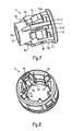
- eine perspektivische Ansicht des Innenteils;
- Fig. 8
- eine perspektivische Ansicht des Außenteils;
- Fig. 9
- eine perspektivische Ansicht des längsgeschnittenen Ausführungsbeispiels nach
Fig. 1 im unverformten Zustand; - Fig. 10
- die Ansicht des Ausführungsbeispiels nach
Fig. 9 im verformten Zustand; - Fig. 11
- eine perspektivische Ansicht des Außenteils mit Sicherungshaken und
- Fig. 12
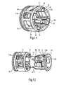
- eine Explosivdarstellung des Außenteils und des Innenteils ohne Keilflächen zur Verdeutlichung des Betätigungsmittels und des zugehörigen Gegenprofils.
-
Fig. 1 stellt ein Ausführungsbeispiel der erfindungsgemäßen Kupplungsvorrichtung mit den wichtigsten Bauteilen dar, die insbesondere im Bereich der Automobilindustrie zum Verbinden von Fluidleitungen verwendet werden kann. Diese Kupplungsvorrichtung wird auch als Steckkupplung oder Schnellkupplung (Quick Connector) bezeichnet. - Wie in
Fig. 1 dargestellt, weist die Kupplungsvorrichtung eine Halteeinrichtung 1 auf, die ein Außenteil 2 und ein Innenteil 3 umfasst, das im Außenteil 2 angeordnet ist. Das Außenteil 2 dient als Adapter, der im Gehäuse 4 fixiert ist. Das Innenteil 2 ist in Längsrichtung der Kupplungsvorrichtung verschieblich und kann in eine Lösestellung und eine Arretierstellung bewegt werden. Das Innenteil 3 fungiert als Halteelement 10 für einen Stutzen 14 oder ein entsprechend profiliertes Leitungsende, das in das Innenteil 3 eingesteckt wird. Zum Verriegeln des Stutzens 14 wird das Innenteil 3 in die mit A bezeichnete Arretierbewegungsrichtung verschoben. Zum Lösen wird das Innenteil 3 in die mit L bezeichnete Lösebewegungsrichtung verschoben. - Wie insbesondere in
Fig. 7 dargestellt, weist das Innenteil 3 zwei voneinander beabstandete konzentrische Ringabschnitte 11, 12 auf, wobei der von der Einsteckseite (linkes Ende der Kupplungsvorrichtung nachFig. 7 ) entfernte Ringabschnitt 12 breiter ist als der näher an der Einsteckseite angeordnete Ringabschnitt 11. Die beiden Ringabschnitte 11, 12 sind durch Stege 13 miteinander verbunden, die in Längsrichtung der Kupplungsvorrichtung angeordnet sind. Die Stege 13 bilden Längsrippen 5, die äquidistant beabstandet auf dem Umfang des ringförmigen Innenteils 3 angeordnet sind. - Die Ringabschnitte 11, 12 sowie die Stege 13, bzw. Längsrippen 5 sind auch in den Figuren 2 bis 4 und 6 im Längsschnitt dargestellt.
- In den
Figuren 3, 4 und7 ist zu erkennen, dass die von der Einsteckseite entfernten Enden 5a der Längsrippen 5 angeschrägt sind und jeweils eine Keilfläche 3a bilden. Die Keilfläche 3a ist also an dem in Arretierbewegungsrichtung A hinteren Ende 5a jeder Längsrippe 5 vorgesehen. Der Neigungswinkel der Keilfläche 3a, d.h. der Winkel zwischen der Keilfläche 3a und der Längsachse der Kupplungsvorrichtung, ist in der Arretierbewegungsrichtung A geöffnet. Der Neigungswinkel beträgt ca. 30° und kann in einem Bereich von 5° bis 45°, einschließlich aller Zwischenwerte innerhalb dieser Grenzen, variiert werden. Je nach Länge oder Durchmesser der Kupplungsvorrichtung können sich andere, insbesondere engere Bereichsgrenzen des Neigungswinkels als zweckmäßig erweisen. - Die in den Keilflächen 3a auslaufenden Längsrippen 5 sind ferner in den
Figuren 3, 4 im Längsschnitt dargestellt. - Die Anzahl von vier Stegen 13 kann ebenfalls variiert werden. Es ist auch möglich, nur zwei Stege 13 und im Extremfall lediglich einen Steg 13 zu verwenden. Eine größere Anzahl von Stegen 13 ist ebenfalls möglich.
- In
Fig. 1 ist weiter zu erkennen, dass die als Längsrippen 5 ausgebildeten Stege 13 einen im wesentlichen rechteckigen Querschnitt mit im wesentlichen gleich langen Kanten aufweisen. Die beiden zwischen den Längsrippen 5 angeordneten Stege 13, die inFig. 1 auf der Schnittachse III-III angeordnet sind, weisen in Umfangsrichtung erstreckte Kanten auf, die länger sind als die entsprechenden Kanten der Rippen 5. Die zwischen den Längsrippen 5 angeordneten Stege 13 sind deshalb breiter als die Längsrippen 5, wie auch inFig. 7 zu erkennen. - Die breiteren Stege 13 sind, ebenso wie die Längsrippen 5, mit Keilflächen 3a versehen, die an den jeweils in Arretierbewegungsrichtung A hinteren Enden der breiten Stege 13 angeordnet sind (siehe
Fig. 3 ). InFig. 7 ist ferner zu sehen, dass die Keilflächen 3a von den breiten Stegen 13 abgesetzt und nicht über die volle Breite der Stege 13 erstreckt sind. Die Breite der Keilflächen 3a, die sich an die breiten Stege 13 anschließen, entspricht im Wesentlichen der Breite der Keilflächen 3a, die an den Längsrippen 5 angeformt sind. - In der radial außen angeordneten Oberfläche der breiten Stege 13 ist eine Ausnehmung in der Form eines Gegenprofils 3b ausgebildet. Dieses Gegenprofil 3b ist für den Eingriff mit einem an einer Taste 7a vorgesehenen Profil 7b vorgesehen und ermöglicht die axiale Fixierung des Innenteils 3 in der Lösestellung. Wie besonders gut in
Fig. 3 zu erkennen, ist die Oberfläche 13a der breiten Stege 13 im Bereich des Gegenprofils 13b etwas radial nach innen abgesenkt und bildet eine Ausbuchtung, in der das vorstehende Profil 7b bei nicht betätigter Taste 7a frei bewegbar ist. - In dem Freiraum zwischen jedem breiten Steg 13 und jeder Längsrippe 5 ist eine Raste 15 vorgesehen, die elastisch federnd an dem breiteren Ringabschnitt 12 angebracht ist. Die Rasten 15 sind jeweils in Längsrichtung der Kupplungsvorrichtung erstreckt und äquidistant auf dem Umfang des Ringsabschnitts 12 beabstandet.
- Jede Raste 15 weist ein Arretierelement 15a und einen dem Arretierelement 15a gegenüber angeordneten Mitnehmer 15b auf, wie in
Fig. 2 dargestellt. Das Arretierelement 15a ist auf der Außenseite der Raste 15 angeordnet und als radial nach außen abgesetzte Kante bzw. Schulter ausgebildet. Die Schulter des Arretierelementes 15a weist eine radial erstreckte Schulterfläche und eine axial erstreckte Schulterfläche auf. Die Schulter bildet somit einen zur Einsteckseite der Kupplungsvorrichtung (rechtes Ende inFig. 2 ) geöffneten Winkel. Das Arretierelement 15a ist auch in denFiguren 6 und7 zu erkennen. - Auf der Innenseite der Raste 15 ist der Mitnehmer 15b vorgesehen, der einen radial innen angeordneter Anschlag 15c aufweist. Der Anschlag 15c umfasst eine bezüglich der Längsachse der Kupplungsvorrichtung geneigte Fläche, deren Neigungswinkel in der Lösebewegungsrichtung L geöffnet ist. Unter dem Neigungswinkel der Fläche des Anschlags 15c wird der Winkel zwischen der Längsachse der Kupplungsvorrichtung und der Fläche des Anschlags 15c verstanden.
- Die Raste 15 weist ferner eine weitere radial innen angeordnete, gegenüber der Längsachse der Kupplungsvorrichtung geneigte Fläche 15d auf, deren Neigungswinkel in der Arretierbewegungsrichtung A geöffnet ist, wie in
Fig. 2 dargestellt. Der Anschlag 15c bzw. die geneigte Fläche des Anschlags 15c und die weitere geneigte Fläche 15d bilden einen keilförmigen Vorsprung 15e, der inFig. 2 dargestellt ist. - Die jeweiligen keilförmigen Vorsprünge 15e der Rasten 15 sind auf einem gedachten kreisförmigen Durchmesser angeordnet, der kleiner ist als der Außendurchmesser des in
Fig. 2 dargestellten Bundes 14b des Stutzens 14. Im montierten Zustand hintergreift somit der keilförmige Vorsprung 15e der Raste 15 den Bund 14b. - Der keilförmige Vorsprung 15e der Raste 15 ist ferner in
Fig. 5 gezeigt. Das inFig. 5 gezeigte Ausführungsbeispiel weicht insofern von dem Ausführungsbeispiel nachFig. 1 ab, als die Keilflächen 3a nur an den Rippen 5 vorgesehen sind. - Im Folgenden wird der Aufbau des Außenteils 2 näher erläutert.
-
Fig. 6 zeigt, dass das Außenteil 2 zwei Ringabschnitte 2d, 2e umfasst, die konzentrisch angeordnet und voneinander beabstandet sind. Der beiden Ringabschnitte 2d, 2e weisen jeweils eine Nut auf, so dass die beiden Ringabschnitte 2d, 2e mit dem Gehäuse 4 vercrimpt werden können, wie in denFiguren 2 bis 4 dargestellt. - Die beiden Ringabschnitte 2d, 2e sind durch Längsstege 2f verbunden, die äquidistant beabstandet auf dem Umfang der beiden Ringabschnitte 2d, 2e angeordnet sind. Dadurch wird jeweils zwischen zwei Stegen 2f ein Durchbruch 2c gebildet, der im montierten Zustand jeweils einer Raste 15 zugeordnet ist, die teilweise in den jeweiligen Durchbruch 2c hineinragt, wie beispielsweise in
Fig. 2 zu erkennen. - Die Stege 2f sind an ihrer Innenseite, d.h. radial nach innen weisend, mit einer Längsnut 6 ausgebildet, deren Breite und Tiefe an die Abmaße der Längsrippen 5 des Innenteils angepasst sind, so dass die Längsrippen 5 in den Längsnuten 6 gleitverschieblich bewegbar sind. Die Anordnung der Längsrippen in den Längsnuten 6 ist besonders gut in
Fig. 1 zu erkennen. - Wie ferner in
Fig. 4 dargestellt, weist jede Längsnut 6 an ihrem in Arretierbewegungsrichtung A des Innenteils 3 hinteren Ende 6a eine Keilfläche 2a auf. Diese Keilfläche 2a ist komplementär zur Keilfläche 3a der am Innenteil 3 angeformten Längsrippe 5 ausgebildet. Das bedeutet, dass der Neigungswinkel der Keilfläche 2a des Außenteils 2 dem Neigungswinkel der Keilfläche 3a des Innenteils 3 entspricht. Die Keilflächen 2a, 3a liegen somit in der Lösestellung flächig aufeinander. - Ferner ist das Außenteil 2 mit einem Betätigungsmittel 7 versehen, das, wie in den
Figuren 1, 3 dargestellt, als Taste 7a ausgebildet ist. Bei dem in denFiguren 1 ,3 dargestellten Ausführungsbeispiel sind zwei um 180° versetzte Tasten 7a vorgesehen, die jeweils im Wesentlichen identisch ausgebildet sind. Diese Anordnung der Tasten 7a gestattet eine einfache und ergonomisch günstige manuelle Betätigung. Es ist auch möglich, nur eine Taste 7a vorzusehen. - Die Tasten 7a sind jeweils an einer Längsseite des Außenteils 2 angebracht und können in radialer Richtung bewegt werden (
Fig. 3 ). Dazu ist jede Taste 7a mittels Stegen 7c mit den beiden Ringabschnitten 2d, 2e des Außenteils 2 verbunden, wie inFig. 6 dargestellt. Dabei sind die die Taste 7a mit dem einsteckseitigen Ringabschnitt 2d verbindenden Stege 7c V-förmig angeordnet. Der die Taste 7a mit dem entfernteren Ringabschnitt 2e verbindende Steg 7c ist etwas breiter als die V-förmigen Stege 7c ausgebildet. Die Stege 7c sind elastisch und gestatten eine Verschiebung der Taste 7a bei deren Betätigung in radialer Richtung des Außenteils 2. - In den
Figuren 1 ,3 ist ferner dargestellt, dass die Taste 7a ein radial innen angeordnetes Profil 7b in der Form eines Vorsprungs aufweist. Die Kontur des Profils 7b entspricht im Wesentlichen der Kontur des am Innenteil 3 ausgebildeten Gegenprofils 3b, wie inFig. 3 gezeigt. In der Lösestellung sind das Profil 7b der Taste 7a und das Gegenprofil 3b des Innenteils 3 in Gegenüberstellung angeordnet, so dass bei Betätigung der Taste 7a das Profil 7b in das Gegenprofil 3b eingreift und das Innenteil 3 mit dem Außenteil 2 verriegelt. Dadurch wird eine axiale Bewegung des Innenteils 3 verhindert und das Innenteil 3 in der Lösestellung gehalten. - Es ist auch möglich, das Profil 7b und das Gegenprofil 3b auf andere Weise auszubilden. Beispielsweise kann am Innenteil 3 ein Vorsprung und an der radial innen angeordneten Fläche der Taste 7a eine komplementär geformte Ausnehmung vorgesehen sein, die miteinander bei Betätigung der Taste 7a in Eingriff gebracht werden können. Ferner ist es möglich, anstelle der vorstehend beschriebenen formschlüssigen Verbindung zwischen dem Außenteil 2 und dem Innenteil 3 eine reibschlüssige Verbindung bei Betätigung der Taste 7a herzustellen, wodurch ebenfalls eine axiale Bewegung des Innenteils 3 verhindert wird.
- In den
Figuren 3 und8 ist dargestellt, dass der in Arretierbewegungsrichtung hintere Ringabschnitt 2e im Bereich des Betätigungsmittels 7, d.h. axial fluchtend mit der Taste 7a, eine Keilfläche 2a aufweist. Diese Keilfläche 2a ist komplementär zur Keilfläche 3a am Innenteil 3 ausgebildet, wie inFig. 3 dargestellt. Die axiale Anordnung der Keilfläche 2a bezüglich der Taste 7a ist inFig. 8 dargestellt. Das bedeutet, dass der in Arretierbewegungsrichtung A hintere Ringabschnitt 2e des Außenteils 2 in Arretierbewegungsrichtung A, d.h. in Richtung der Taste 7a, verjüngt ist. Der Neigungswinkel der Keilfläche 2a des Außenteils 2 entspricht dem Neigungswinkel der komplementären Keilfläche 3a des Innenteils 3. - Es ist auch möglich, nur die zwischen den Tasten 7a angeordneten Längsnuten 6 mit entsprechenden Keilflächen 2a zu versehen und den in Arretierbewegungsrichtung A hinteren Ringabschnitt 2e des Außenteils 2 mit einer quer zur Längsrichtung des Außenteils 2 erstreckten Anschlagfläche auszubilden, wie in
Fig. 5 dargestellt. - Das Außenteil 2 kann eine zusätzliche Sicherung gegen Versagen bei Verformung der Kupplungsvorrichtung durch einen Unfall aufweisen. Diese zusätzliche Sicherung umfasst einen Rasthaken, der an einem der Stege 2f zwischen zwei Durchbrüchen 2c vorgesehen ist und radial nach innen vorsteht. Der Rasthaken hintergreift den Bund 14a eines in die Kupplungsvorrichtung eingeführten Stutzens 14 oder eines Leitungsendes und verhindert zusätzliche, dass die Leitung aus der Kupplungsvorrichtung herausgezogen werden kann, wenn diese verformt wird. Dazu hat der Rasthaken eine im Wesentlichen keilförmige Gestalt, wobei eine Schrägfläche des Rasthakens im Wesentlichen in axialer Richtung erstreckt und in der Arretierbewegungsrichtung A verjüngt ist, wie in
Fig. 11 gezeigt. Dadurch kann der Bund 14a des Stutzens 14 leicht über den Rasthaken beim Einstecken desselben in die Kupplungsvorrichtung geschoben werden. Der Rasthaken umfasst ferner eine im Wesentlichen senkrecht zur Längsrichtung des Außenteils 2 angeordnete Anschlagfläche, die mit dem Bund 14a des Stutzens 14 zusammenwirkt und ein Herausziehen desselben verhindert. - Im Folgenden wird die Ausgestaltung des Gehäuses 4 erläutert.
- In den
Figuren 2 bis 4 und10 ist dargestellt, dass das Gehäuse 4 eine Öffnung 4a zum Einstecken eines Stutzens 14 oder eines Leitungsendes in die Kupplungsvorrichtung aufweist,
wobei der Durchmesser der Einstecköffnung 4a derart an den Durchmesser des Bundes 14a des Stutzens 14 angepasst ist, dass der Bund 14a bei einer Verformung des Gehäuses 4 eine Kante 4b der Öffnung 4a hintergreift, so dass ein Trennen der Leitung und der Kupplungsvorrichtung verhindert wird, wenn das Gehäuse 4 verformt ist. Dazu ist das im Bereich der Halteeinrichtung 1 zylindrisch ausgebildete Gehäuse 4 an dessen einsteckseitigen Ende 4c radial nach innen gebogen. Der Durchmesser der Einstecköffnung 4e ist geringfügig größer als der Durchmesser des Bundes 14a. Insbesondere ist der Durchmesser der Öffnung 4a in dem Betrag von 0,1 bis 1 mm, insbesondere von 0,4 bis 0,8 mm, größer als der Durchmesser des Bundes 14a. - Im unverformten Zustand sind die radiale Außenseite des Bundes 14a und die Öffnung 4a des Gehäuses 4 konzentrisch angeordnet, so dass der Bund 14a durch die Öffnung 4a in das Gehäuse 4 eingeführt werden kann. Bei einer Verformung des Gehäuses 4 wird die konzentrische Anordnung des Bundes 14a und der Öffnung 4a verändert, so dass der Bund 14a und das Gehäuse 4a exzentrisch zueinander angeordnet sind. Dadurch wird erreicht, dass der Bund 14a zumindest teilweise die Kante 4b der Öffnung 4a hintergreift, wodurch eine wirksame Auszugsicherung geschaffen wird.
- Aufgrund der geringfügigen Durchmesserdifferenz zwischen der Öffnung 4a und dem Bund 14a führt auch eine leichte Verformung des einsteckseitigen Endes 4c im Bereich der Öffnung 4a zu dem gewünschten Effekt, da die Öffnung 4a ihren kreisförmigen Querschnitt verliert, so dass das kreisförmige Profil des Bundes 14a die Kante 4b der verformten Öffnung 4a stellenweise hintergreift und ein Herausziehen des Stutzens 14 bzw. des Leitungsendes aus der Kupplungsvorrichtung verhindert wird.
- Die Anordnung des Stutzens 14 und des Gehäuses 4 im unverformten und verformten Zustand sind in den
Figuren 9 und 10 dargestellt. Insbesondere inFig. 10 ist gezeigt, dass der Bund 14a die Kante 4b der Öffnung 4a im verformten Zustand des Gehäuses 4 hintergreift, wodurch eine axiale Bewegung des Stutzens 14, d.h. ein Herausziehen des Stutzens 14 aus der Kupplungsvorrichtung, unterbunden wird. - Das Gehäuse 4 ist im Bereich der Halteeinrichtung mit einem zylindrischen Abschnitt 9 (s.
Figur 3 ) ausgebildet, wobei in der Mantelfläche 9a des Abschnittes 9 zwei um 180° versetzte radiale Öffnungen 8 vorgesehen sind. Im montierten Zustand sind die Tasten 7a in diesen Öffnungen 8 angeordnet und somit zur Betätigung zugänglich. - Das vorstehend beschriebene Gehäuse 4 kann mit einem Stutzen 14 kombiniert werden, der entweder einen Bund 14a (
Figuren 9, 10 ) oder zwei Bünde 14a, 14b (Figuren 2 bis 4 ) aufweist. Im Fall des Stutzens 14 mit nur einem Bund 14a fungiert der eine Bund 14a sowohl zur Betätigung des Mitnehmers 15b der Taste 15 am Innenteil 3 als auch als Auszugsicherung in Verbindung mit der (verformten) Kante 4b der Öffnung 4a des Gehäuses 4. Im Fall des Stutzens 14 mit zwei Bünden 14a, 14b sind die vorstehend erläuterten Funktionen getrennt, wobei der in Arretierbewegungsrichtung A hintere Bund 14b mit dem Mitnehmer 15b der Raste 15 und der in Arretierbewegungsrichtung A vordere Bund 14a mit der (verformten) Kante 4b der Öffnung 4a zusammenwirkt. - Die vorstehend beschriebenen Elemente sind im montierten Zustand wie folgt angeordnet.
- Im montierten Zustand ist der Stutzen 14 in das Innenteil 3 eingesteckt, das im Außenteil 2 gehalten ist. Das Außenteil 2 ist mit dem Gehäuse 4 fest verbunden, beispielsweise durch Vercrimpen. Wie in den
Figuren 1, 2 und6 dargestellt, sind die Längsrippen 5 des Innenteils 3 in den Längsnuten 6 des Außenteils 2 längsverschieblich geführt, wobei die Rasten 15 in den Durchbrüchen 2c des Außenteils 2 angeordnet sind und teilweise in diese hineinragen. - Die Rasten 15 ragen dabei jeweils so weit in die jeweiligen Durchbrüche 2c, dass der ringförmige Anschlag 2b des Außenteils 2, insbesondere die radial innen angeordnete Kante des Anschlags 2b in das Arretierelement 15a eingreifen kann. Dazu ist die Kante des Anschlags 2b des Außenteils 2 geringfügig weiter radial außen angeordnet als die in Längsrichtung erstreckte Schulterfläche des Anschlags 15, wie in
Fig. 2 dargestellt. Dadurch können die in radialer Richtung erstreckte Schulterfläche des Arretierelements 15a und die ebenfalls in radialer Richtung erstreckte Anschlagfläche des Anschlags 2b in Berührung kommen, wodurch eine weitere axiale Bewegung des Innenteils 3 in die Arretierbewegungsrichtung A verhindert wird. - Ferner ist einer der beiden Bünde 14a, 14b, nämlich der in Arretierbewegungsrichtung A hintere Bund 14b in Arretierbewegungsrichtung A hinter dem Mitnehmer 15b der Raste 15 angeordnet, wie in
Fig. 2 dargestellt. - Das Innenteil 3 wird dadurch in die Arretierstellung gebracht, dass der Stutzen 14 in Arretierbewegungsrichtung A verschoben wird. Dadurch kommt der Bund 14b in Anschlag mit dem Mitnehmer 15b der Raste 15, insbesondere mit der geneigten Anschlagfläche 15c. Durch die in Arretierbewegungsrichtung A ausgeführte Verschiebung des Stutzens 14 wird das Innenteil 3 mitgenommen und führt ebenfalls eine axiale Bewegung in Arretierbewegungsrichtung A aus. Dabei soll die Federkraft der Raste 15 so eingestellt sein, dass ein radiales Ausweichen der Raste 15 aufgrund der in Arretierbewegungsrichtung A auf die Raste 15 vom Stutzen 14 übertragenen Kraft nicht erfolgt. In der Arretierstellung ist das Arretierelement 15a in Eingriff mit dem Anschlag 2b des Außenteils 2. Dabei greift die Kante des Anschlags 2b des Außenteils 2 in das schulterförmige Arretierelement 15a ein, so dass sowohl eine axiale Bewegung des Innenteils als auch eine radiale Ausweichbewegung der Raste 15 verhindert wird. Dadurch wird der Mitnehmer 15b bzw. die schräge Anschlagfläche 15c der Raste 15 sowohl in axialer als auch in radialer Richtung arretiert, so dass ein Herausziehen des Stutzens 14 aus der Kupplungsvorrichtung verhindert wird.
- Durch Verschieben des Innenteils 3 in der Lösebewegungsrichtung L kommt das Arretierelement 15a der Raste 15 vom Anschlag 2b des Außenteils 2 frei, wodurch eine radial nach außen gerichtete Öffnungsbewegung der Raste 15 im jeweiligen Durchbruch 2c des Außenteils 2 ermöglicht wird. Die zur Verschiebung des Innenteils 3 in die Lösestellung erforderliche axiale Kraft kann entweder direkt in das Innenteil 3 oder über den Stutzen 14 in das Innenteil 3 eingeleitet werden. Dabei schlägt der Bund 14b des Stutzens 14 an einem geeigneten Anschlag des Innenteils 3 an und bewegt diesen durch eine entsprechende Bewegung des Stutzens 14 in die Lösebewegungsrichtung L in die Kupplungsvorrichtung hinein. Die Lösestellung ist erreicht, wenn das an der Taste 7a vorgesehene Profil 7b und das Gegenprofil 3b des Innenteils. 3 in Gegenüberstellung angeordnet (
Fig. 3 ) und die Keilflächen 2a, 3a des Außenteils 2 bzw. des Innenteils 3 in Kontakt sind (Figuren 3, 4 ). - Zum Lösen wird die Taste 7a betätigt, so dass das Profil 7b und das Gegenprofil 3b formschlüssig verbunden werden und eine axiale Verschiebebewegung des Innenteils 3 verhindert wird, so dass dieses in der Lösestellung gehalten wird. Dann kann der Stutzen 14 entgegen der Lösebewegungsrichtung L, d.h. in der Arretierbewegungsrichtung A aus der Kupplungsvorrichtung herausgezogen werden, ohne dass das Innenteil 3 in die Arretierstellung bewegt wird. Durch die axiale Bewegung des Stutzens 14 werden die Rasten 15 aufgespreizt, wobei der Bund 14b an der geneigten Anschlagfläche 15c des Mitnehmers 15b entlanggleitet. Nachdem der Bund 14b den radial nach innen erstreckten keilförmigen Vorsprung 15e der Raste 15 überwunden hat, kann der Stutzen 14 widerstandsfrei aus der Kupplungsvorrichtung abgezogen werden.
- Bei der Zwangsverriegelung der Kupplungsvorrichtung, ausgelöst durch eine Verformung des Gehäuses 4, wird das Innenteil 3 zwangsweise aus der Lösestellung in die Arretierstellung verschoben und dort gehalten. Dazu wirken die Keilflächen 2a des Außenteils mit den Keilflächen 3a des Innenteils zusammen. Durch die Verformung des Gehäuses 4 werden die in Arretierbewegungsrichtung A hinteren Ringabschnitte 2e des Außenteils 2 und 12 des Innenteils 3 mit einer im Wesentlichen in radialer Richtung wirkenden Kraft beaufschlagt. Aufgrund der in Längsrichtung der Kupplungsvorrichtung geneigten Keilfläche 2a, 3a wird eine in Arretierbewegungsrichtung A gerichtete Axialkraft erzeugt, die das Innenteil 3 in die Arretierstellung zwangsverschiebt und das Innenteil in der Arretierstellung festlegt.
- Bei dem beschriebenen Ausführungsbeispiel ist das Außenteil 2 im Gehäuse 4 fixiert und bezogen auf das axial bewegliche Innenteil 3 ortsfest angeordnet. Bei dieser Anordnung des Außenteils 2 und des Innenteils 3 wird die in Arretierbewegungsrichtung A gerichtete Axialkraft dadurch erzeugt, dass der Neigungswinkel der Keilflächen 2a, 3a in der Arretierbewegungsrichtung A des Innenteils geöffnet ist.
- Es ist auch möglich, das Innenteil 3, bezogen auf das Außenteil 2, ortsfest, d.h. mit dem Gehäuse fest verbunden, vorzusehen, wobei das Außenteil 2 in die Arretierstellung bewegt wird. In diesem Fall wäre die Ausrichtung des Neigungswinkels der Keilflächen entsprechend anzupassen, um eine bei Verformung des Gehäuses in die Arretierbewegungsrichtung wirkende Axialkraft zu erzeugen.
- Generell kommt es darauf an, dass eine Relativbewegung zwischen dem Innenteil 3 und dem Außenteil stattfindet, so dass zwei unterschiedliche Positionen (Lösestellung und Arretierstellung) eingenommen werden können.
- Durch die Anpassung des Durchmessers der Öffnung 4a des einsteckseitigen Endes 4c des Gehäuses 4 wird eine zusätzliche Auszugsicherung geschaffen, die eingreift, wenn die vorstehend beschriebene Zwangsverriegelung versagt. Da bei einer Verformung des Gehäuses 4 die Öffnung 4a ebenfalls verformt wird, so dass der ursprüngliche kreisförmige Querschnitt der Öffnung 4a verändert wird, wird erreicht, dass der Bund 14a des Stutzens 14 die Kante 4b der Öffnung 4a hintergreift und am Herausrutschen aus der Kupplungsvorrichtung gehindert wird (
Fig. 10 ). - Es hat sich als zweckmäßig erwiesen, wenn das Innenteil 3 zwei um 180° versetzte Stege 13 mit Längsrippen 5 sowie zwei ebenfalls um 180° versetzte breitere Stege 13 aufweist, die jeweils mit einem Betätigungsmittel 7 versehen sind. Die breiten Stege 13 und die als Längsrippen 5 ausgebildeten Stege sind jeweils um 90° zueinander versetzt auf dem Umfang des Innenteils 3 angeordnet. Die jeweils zugeordneten Längsnuten 6 des Außenteils 2 sind an die Maße der Längsrippen bzw. der breiten Stege 13 angepasst und gestatten die längsverschiebliche Führung des Innenteils 3 im Außenteil 2. Eine andere Anzahl von Stegen 13, beispielsweise mehr als zwei Stege 13 mit den Längsrippen 5 oder mehr als zwei breite Stege 13 mit Betätigungsmitteln 7 ist möglich. Es ist auch möglich, nur zwei breite Stege 13 vorzusehen, die um 180° versetzt auf dem Umfang des Innenteils 3 angeordnet sind. In diesem Fall könnten die jeweils auf einer Seite angeordneten Rasten 15 zu einer halbkreisförmigen Raste 15 verbunden werden, so dass das Innenteil 3 zwei sich über einen größeren Teil des Umfangs erstreckende Rasten aufweist. Die Keilflächen 2a, 3a können nur an den Längsrippen 5 oder nur im Anschluss an das Betätigungsmittel 7 vorgesehen sein. Die Keilflächen 2a, 3a können in ihrer Breite der Breite der Längsrippen 5 entsprechen. Es ist auch möglich, die Keilflächen 2a, 3a mit einer größeren Breite auszubilden, so dass die Keilflächen 2a, 3a über einen größeren Teil des Umfangs des Innenteils 3 erstreckt sind.
- Die Form des Profils 7b an der Taste 7a kann beliebig variiert werden, wobei gewährleistet sein muss, dass das Profil 7b und das Gegenprofil 3b im Innenteil 3 formschlüssig in Eingriff gebracht werden können. Anstelle der Festlegung des Innenteils 3 bezüglich des Außenteils 2 durch eine formschlüssig Verbindung kann eine axiale Fixierung des Innenteils auch durch eine reibschlüssige Verbindung bei Betätigung der Taste 7a des Außenteils 2 erfolgen.
- Die Anpassung des Durchmessers der Öffnung 4a an den Außendurchmesser des Bundes 14a kann durch einfaches Umbiegen des einsteckseitigen Endes 4c des Gehäuses 4 erfolgen. In diesem Fall ist das Gehäuse 4 einstückig aufgebaut. Anstelle des einstückigen Gehäuseaufbaus kann das Gehäuse auch zweiteilig aufgebaut sein, wobei anstelle des radial nach innen gebogenen Endes 4c des Gehäuses 4 ein geeigneter Aufsatz vorgesehen ist, der mit dem Gehäuse 4 verbunden werden kann und eine im Hinblick auf den Durchmesser angepasste Einstecköffnung aufweist.
- Die Kupplungsvorrichtung ist zur Verbindung mit einem Stutzen 14 geeignet, an den eine Leitung angeschlossen werden kann. Die Kupplungsvorrichtung ist ferner zur Verbindung mit einem geeignet profilierten Leitungsende geeignet.
- Insgesamt kommt es darauf an, dass die durch Verformung des Gehäuses erzeugte Radialkraft in eine Radialkomponente und eine Axialkomponente aufgespalten wird. Dies kann generell auch dadurch erreicht werden, dass eine der beiden komplementär ausgebildeten Keilflächen durch ein gleichwirkendes Element ausgetauscht wird, so dass nur eine Keilfläche vorgesehen ist. Beispielsweise könnte nur am Außenteil 2 die Keilfläche 2a vorgesehen sein und die Keilfläche 3a des Innenteils 3 durch eine am Innenteil 3 ausgebildete Radialkante ersetzt sein, die im Bereich der Keilfläche 2a des Außenteils 2 angeordnet ist.
- Es wäre auch möglich, nur die Keilfläche 3a des Innenteils 3 vorzusehen und anstelle der Keilfläche 2a des Außenteils 2 einen Vorsprung im Bereich der Keilfläche 3a des Innenteils 3 anzubringen, der in der Lösestellung mit der Keilfläche 3a des Innenteils 3 in Berührung ist.
- In beiden Fällen würde durch die einzige Keilfläche die durch Verformung des Gehäuses eingeleitete Radialkraft in eine axial gerichtete Kraft umgewandelt werden, die zur Verschiebung des Innenteils in die Arretierstellung genutzt werden kann. Dabei würde es nicht zu einer flächigen, sondern zu einer linienförmigen Berührung zwischen der Keilfläche und dem Austauschelement kommen, die im Hinblick auf die Stabilität der Gesamtanordnung weniger vorteilhaft ist als die mit den beiden Keilflächen 2a, 3a erzeugte Flächenpressung. Die Wirkung, das Innenteil 3 bzw. das Außenteil 2 in die Arretierstellung zwangszuverschieben, würde jedoch auch bei Verwendung nur einer Keilfläche erzielbar sein.
- Die Kupplungsvorrichtung kann auf allen Gebieten eingesetzt werden, auf denen fluidführende Leitungen miteinander gekoppelt werden. Die Kupplungsvorrichtung ist insbesondere für die Automobilindustrie, beispielsweise zum Verbinden von Kraftstoffleitungen, vorgesehen.
Claims (20)
- Kupplungsvorrichtung zum Verbinden von Leitungen mit- einem Gehäuse (4), in dem eine Öffnung (4a) vorgesehen ist,- einer Halteeinrichtung (1), die im Gehäuse (4) angeordnet ist, und- einem Leitungsende oder einem Stutzen (14), der in das Gehäuse (4) durch die Öffnung (4a) einführbar und mit der Halteeinrichtung (1) arretierbar ist, wobei das Leitungsende bzw. der Stutzen (14) wenigstens einen Bund (14a, 14b) aufweist, und das Gehäuse (4) im Bereich der Halteeinrichtung (1) zylindrisch ausgebildet und zur Bildung der Öffnung (4a) an dessen Ende (4c) radial nach innen gebogen ist,dadurch gekennzeichnet, dass der Durchmesser der Öffnung (4a) derart an den Durchmesser des Bundes (14a, 14b) angepasst ist, dass der Bund (14a, 14b) bei einer Verformung des Gehäuses (4), die die konzentrische Anordnung des Bundes (14a) und der Öffnung (4a) verändert, eine Kante (4b) der Öffnung (4a) hintergreift.
- Kupplungsvorrichtung nach Anspruch 1, dadurch gekennzeichnet, dass der Durchmesser der Öffnung (4a) um einen Betrag von 0,1 bis 1 mm, insbesondere von 0,4 bis 0,8 mm größer als der Durchmesser des Bundes (14a, 14b) ist.
- Kupplungsvorrichtung nach Anspruch 1 oder 2, dadurch gekennzeichnet, dass ein Innenteil (3) zwischen einer Arretierstellung und einer Lösestellung in Längsrichtung der Halteeinrichtung (1) bewegbar ist.
- Kupplungsvorrichtung nach Anspruch 3, dadurch gekennzeichnet, dass ein Außenteil (2) wenigstens ein Betätigungsmittel (7) zum Fixieren des Innenteils (3) aufweist.
- Kupplungsvorrichtung nach Anspruch 4, dadurch gekennzeichnet, dass das Betätigungsmittel (7) im Bereich einer im Gehäuse (4) vorgesehenen Öffnung (8) angeordnet ist.
- Kupplungsvorrichtung nach Anspruch 5, dadurch gekennzeichnet, dass ein Abschnitt (9) des Gehäuses (4) zumindest im Bereich der Halteeinrichtung (1) zylindrisch ausgebildet ist, wobei die Öffnung (8) in der Mantelfläche (9a) des Abschnitts (9) angeordnet ist.
- Kupplungsvorrichtung nach wenigstens einem der Ansprüche 4 bis 6, dadurch gekennzeichnet, dass das Betätigungsmittel (7) wenigstens eine radial bewegbare Taste (7a) aufweist, die mit dem Innenteil (3), insbesondere in der Lösestellung, formschüssig oder reibschlüssig, in Eingriff bringbar ist.
- Kupplungsvorrichtung nach Anspruch 7, dadurch gekennzeichnet, dass die Taste (7a) ein Profil (7b), insbesondere einen Vorsprung oder eine Ausnehmung, und das Innenteil (3) ein passendes Gegenprofil (3b), insbesondere eine Ausnehmung oder einen Vorsprung, aufweisen, die in der Lösestellung gegenüber angeordnet und durch Betätigen der Taste (7a) in Eingriff bringbar sind.
- Kupplungsvorrichtung nach Anspruch 8, dadurch gekennzeichnet, dass das Innenteil (3) ein Halteelement (10) mit zwei konzentrisch angeordneten und beabstandeten Ringabschnitten (11, 12) umfasst, die durch in Längsrichtung der Halteeinrichtung (1) angeordnete Stege (13) verbunden sind, wobei das Gegenprofil (3b) in wenigstens einem der Stege (13) ausgebildet ist.
- Kupplungsvorrichtung nach Anspruch 9, dadurch gekennzeichnet, dass eine Oberfläche (13a) des Steges (13), in dem das Gegenprofil (3b) ausgebildet ist, im Bereich des Gegenprofils (3b) radial nach innen abgesenkt ist.
- Kupplungsvorrichtung nach wenigstens einem der Ansprüche 3 bis 10, dadurch gekennzeichnet, dass wenigstens eine, bezogen auf die Längsachse der Halteeinrichtung, geneigt angeordnete Keilfläche (2a) am Außenteil (2) vorgesehen ist, die mit wenigstens einer komplementär ausgebildeten Keilfläche (3a) zusammenwirkt, die am Innenteil (3) vorgesehen ist.
- Kupplungsvorrichtung nach Anspruch 11, dadurch gekennzeichnet, dass das Außenteil (2) im Gehäuse (4) fixiert und das Innenteil (3) in die Arretierstellung und Lösestellung bewegbar ist, wobei der Neigungswinkel der Keilflächen (2a, 3a) in der Arretierbewegungsrichtung des Innenteils (3) geöffnet ist.
- Kupplungsvorrichtung nach Anspruch 11 oder 12, dadurch gekennzeichnet, dass die am Innenteil (3) vorgesehene wenigstens eine Keilfläche (3a) an einem in Arretierbewegungsrichtung des Innenteils (3) hinteren Ende (5a) wenigstens einer am Innenteil (3) angeformten Längsrippe (5) ausgebildet ist.
- Kupplungsvorrichtung nach Anspruch 13, dadurch gekennzeichnet, dass das Innenteil (3) zwei, drei oder vier Längsrippen (5) aufweist, die jeweils mit einer Keilfläche (3a) ausgebildet sind.
- Kupplungsvorrichtung nach Anspruch 13 oder 14, dadurch gekennzeichnet, dass die am Außenteil (2) vorgesehene wenigstens eine Keilfläche (2a) an einem in Arretierbewegungsrichtung des Innenteils (3) hinteren Ende (6a) wenigstens einer Längsnut (6) ausgebildet ist, in der die wenigstens eine Längsrippe (5) gleitverschieblich bewegbar ist.
- Kupplungsvorrichtung nach Anspruch 15, dadurch gekennzeichnet, dass eine der Anzahl der Längsrippen (5) entsprechende Anzahl von Längsnuten (6) vorgesehen ist.
- Kupplungsvorrichtung nach wenigstens einem der Ansprüche 3 bis 16, dadurch gekennzeichnet, dass das Innenteil (3) wenigstens eine Raste (15) mit einem radial außen angeordneten Arretierelement (15a) und das Außenteil (2) wenigstens einen Anschlag (2b) aufweist, wobei das Arretierelement (15a) und der Anschlag (2b) in der Arretierstellung zusammenwirken und in der Lösestellung getrennt sind.
- Kupplungsvorrichtung nach Anspruch 17, dadurch gekennzeichnet, dass die wenigstens eine Raste (15) einen Mitnehmer (15b) mit einem radial innen angeordneten Anschlag (15c) aufweist, der entgegen der Arretierbewegungsrichtung des Innenteils (3) angeordnet ist.
- Kupplungsvorrichtung nach Anspruch 18, dadurch gekennzeichnet, dass die wenigstens eine Raste (15) radial federnd ausgebildet ist.
- Kraftfahrzeug mit einer Kupplungsvorrichtung nach wenigstens einem der Ansprüche 1 bis 19.
Applications Claiming Priority (2)
| Application Number | Priority Date | Filing Date | Title |
|---|---|---|---|
| DE102004053539A DE102004053539A1 (de) | 2004-11-05 | 2004-11-05 | Kupplungsvorrichtung zum Verbinden von Leitungen und Kraftfahrzeug mit einer derartigen Kupplungsvorrichtung |
| PCT/EP2005/009672 WO2006048070A1 (de) | 2004-11-05 | 2005-09-08 | Kupplungsvorrichtung zum verbinden von leitungen und kraftfahrzeug mit einer derartigen kupplungsvorrichtung |
Publications (2)
| Publication Number | Publication Date |
|---|---|
| EP1807649A1 EP1807649A1 (de) | 2007-07-18 |
| EP1807649B1 true EP1807649B1 (de) | 2009-08-26 |
Family
ID=35160090
Family Applications (1)
| Application Number | Title | Priority Date | Filing Date |
|---|---|---|---|
| EP05782005A Expired - Lifetime EP1807649B1 (de) | 2004-11-05 | 2005-09-08 | Kupplungsvorrichtung zum verbinden von leitungen und kraftfahrzeug mit einer derartigen kupplungsvorrichtung |
Country Status (5)
| Country | Link |
|---|---|
| EP (1) | EP1807649B1 (de) |
| AT (1) | ATE441058T1 (de) |
| DE (2) | DE102004053539A1 (de) |
| ES (1) | ES2330352T3 (de) |
| WO (1) | WO2006048070A1 (de) |
Families Citing this family (1)
| Publication number | Priority date | Publication date | Assignee | Title |
|---|---|---|---|---|
| DE102018113690A1 (de) | 2018-06-08 | 2019-12-12 | Veritas Ag | Fluidverbindungselement |
Citations (1)
| Publication number | Priority date | Publication date | Assignee | Title |
|---|---|---|---|---|
| FR2780765A1 (fr) * | 1998-07-01 | 2000-01-07 | Caillau Ets | Embout de connexion rapide ayant une piece monobloc formant un organe de verrouillage et une bague de blocage du joint |
Family Cites Families (5)
| Publication number | Priority date | Publication date | Assignee | Title |
|---|---|---|---|---|
| US5161832A (en) * | 1991-10-16 | 1992-11-10 | Huron Products Industries, Inc. | Plastic retainer for fluid coupling |
| DE19619026A1 (de) * | 1996-05-10 | 1997-11-13 | Trinova Gmbh | Schnellkupplung |
| DE19704096C1 (de) * | 1997-02-04 | 1997-12-11 | Rasmussen Gmbh | Steckkupplung zum Verbinden zweier Fluidleitungen |
| DE20014786U1 (de) * | 1999-08-31 | 2000-12-28 | Hewing GmbH, 48607 Ochtrup | Fitting für ein Kunststoffrohr oder ein Kunststoff/Metall-Verbundrohr |
| DE20213806U1 (de) * | 2002-09-06 | 2004-01-15 | Veritas Ag | Steckkupplung |
-
2004
- 2004-11-05 DE DE102004053539A patent/DE102004053539A1/de not_active Ceased
-
2005
- 2005-09-08 ES ES05782005T patent/ES2330352T3/es not_active Expired - Lifetime
- 2005-09-08 AT AT05782005T patent/ATE441058T1/de not_active IP Right Cessation
- 2005-09-08 WO PCT/EP2005/009672 patent/WO2006048070A1/de not_active Ceased
- 2005-09-08 EP EP05782005A patent/EP1807649B1/de not_active Expired - Lifetime
- 2005-09-08 DE DE502005008010T patent/DE502005008010D1/de not_active Expired - Lifetime
Patent Citations (1)
| Publication number | Priority date | Publication date | Assignee | Title |
|---|---|---|---|---|
| FR2780765A1 (fr) * | 1998-07-01 | 2000-01-07 | Caillau Ets | Embout de connexion rapide ayant une piece monobloc formant un organe de verrouillage et une bague de blocage du joint |
Also Published As
| Publication number | Publication date |
|---|---|
| DE102004053539A1 (de) | 2006-05-11 |
| ES2330352T3 (es) | 2009-12-09 |
| DE502005008010D1 (de) | 2009-10-08 |
| ATE441058T1 (de) | 2009-09-15 |
| WO2006048070A1 (de) | 2006-05-11 |
| EP1807649A1 (de) | 2007-07-18 |
Similar Documents
| Publication | Publication Date | Title |
|---|---|---|
| EP1208787B1 (de) | Teleskopierbares Staubsauger-Saugrohr | |
| EP1969279B1 (de) | Kupplungsteil für steckverbinderanordnung | |
| DE19652838C2 (de) | Stecker einer elektrischen Steckverbindung und elektrische Steckverbindung | |
| DE4240136C1 (de) | ||
| EP1626463B1 (de) | Steckverbinder | |
| EP2206943B1 (de) | Kupplungseinrichtung | |
| EP2439439B1 (de) | Verbindungselement für eine Fluidverbindung | |
| WO2011006591A1 (de) | Steckkupplung | |
| DE102004053538A1 (de) | Kupplungsvorrichtung zum Verbinden von Leitungen und Kraftfahrzeug mit einer derartigen Kupplungsvorrichtung | |
| EP2233815A2 (de) | Steckverbinder für Medienleitungen | |
| EP2916396A1 (de) | Elektrischer Rundsteckverbinder mit Push-Pull-Verriegelung | |
| DE69208833T2 (de) | Schnellkupplung | |
| EP1318343A2 (de) | Steckverbindung | |
| DE102020108073A1 (de) | Steckverbinder mit Vormontagesicherung | |
| EP1724510B1 (de) | Steckkupplung | |
| EP3318368B1 (de) | Lösbare stielbefestigungskupplung für arbeitsgeräte | |
| EP2707639B1 (de) | Verbindungseinrichtung sowie verbindungssystem mit einer solchen | |
| DE19707371A1 (de) | Druckmittel-Steckkupplung | |
| EP1969280B1 (de) | Steckteil für steckverbinderanordnung | |
| EP2033266B1 (de) | Leiteranschlussklemme | |
| DE3705610A1 (de) | Loesbare steckverbindung fuer rohrleitungen | |
| DE102022101100A1 (de) | Fluidverbindung | |
| DE10043619B4 (de) | Schnellkupplung zum Verbinden vonn Leitungsenden | |
| DE102004053541A1 (de) | Kupplungsvorrichtung zum Verbinden von Leitungen und Kraftfahrzeug mit einer derartigen Kupplungsvorrichtung | |
| EP1537828B1 (de) | Medizinisches Instrument mit Kupplung für Instrumenteneinsatz |
Legal Events
| Date | Code | Title | Description |
|---|---|---|---|
| PUAI | Public reference made under article 153(3) epc to a published international application that has entered the european phase |
Free format text: ORIGINAL CODE: 0009012 |
|
| 17P | Request for examination filed |
Effective date: 20070504 |
|
| AK | Designated contracting states |
Kind code of ref document: A1 Designated state(s): AT BE BG CH CY CZ DE DK EE ES FI FR GB GR HU IE IS IT LI LT LU LV MC NL PL PT RO SE SI SK TR |
|
| DAX | Request for extension of the european patent (deleted) | ||
| 17Q | First examination report despatched |
Effective date: 20080418 |
|
| GRAP | Despatch of communication of intention to grant a patent |
Free format text: ORIGINAL CODE: EPIDOSNIGR1 |
|
| GRAS | Grant fee paid |
Free format text: ORIGINAL CODE: EPIDOSNIGR3 |
|
| GRAA | (expected) grant |
Free format text: ORIGINAL CODE: 0009210 |
|
| AK | Designated contracting states |
Kind code of ref document: B1 Designated state(s): AT BE BG CH CY CZ DE DK EE ES FI FR GB GR HU IE IS IT LI LT LU LV MC NL PL PT RO SE SI SK TR |
|
| REG | Reference to a national code |
Ref country code: GB Ref legal event code: FG4D Free format text: NOT ENGLISH |
|
| REG | Reference to a national code |
Ref country code: CH Ref legal event code: EP |
|
| REG | Reference to a national code |
Ref country code: IE Ref legal event code: FG4D Free format text: LANGUAGE OF EP DOCUMENT: GERMAN |
|
| REF | Corresponds to: |
Ref document number: 502005008010 Country of ref document: DE Date of ref document: 20091008 Kind code of ref document: P |
|
| REG | Reference to a national code |
Ref country code: ES Ref legal event code: FG2A Ref document number: 2330352 Country of ref document: ES Kind code of ref document: T3 |
|
| LTIE | Lt: invalidation of european patent or patent extension |
Effective date: 20090826 |
|
| PG25 | Lapsed in a contracting state [announced via postgrant information from national office to epo] |
Ref country code: FI Free format text: LAPSE BECAUSE OF FAILURE TO SUBMIT A TRANSLATION OF THE DESCRIPTION OR TO PAY THE FEE WITHIN THE PRESCRIBED TIME-LIMIT Effective date: 20090826 Ref country code: IS Free format text: LAPSE BECAUSE OF FAILURE TO SUBMIT A TRANSLATION OF THE DESCRIPTION OR TO PAY THE FEE WITHIN THE PRESCRIBED TIME-LIMIT Effective date: 20091226 Ref country code: LT Free format text: LAPSE BECAUSE OF FAILURE TO SUBMIT A TRANSLATION OF THE DESCRIPTION OR TO PAY THE FEE WITHIN THE PRESCRIBED TIME-LIMIT Effective date: 20090826 Ref country code: SE Free format text: LAPSE BECAUSE OF FAILURE TO SUBMIT A TRANSLATION OF THE DESCRIPTION OR TO PAY THE FEE WITHIN THE PRESCRIBED TIME-LIMIT Effective date: 20090826 |
|
| NLV1 | Nl: lapsed or annulled due to failure to fulfill the requirements of art. 29p and 29m of the patents act | ||
| PG25 | Lapsed in a contracting state [announced via postgrant information from national office to epo] |
Ref country code: NL Free format text: LAPSE BECAUSE OF FAILURE TO SUBMIT A TRANSLATION OF THE DESCRIPTION OR TO PAY THE FEE WITHIN THE PRESCRIBED TIME-LIMIT Effective date: 20090826 Ref country code: PL Free format text: LAPSE BECAUSE OF FAILURE TO SUBMIT A TRANSLATION OF THE DESCRIPTION OR TO PAY THE FEE WITHIN THE PRESCRIBED TIME-LIMIT Effective date: 20090826 Ref country code: SI Free format text: LAPSE BECAUSE OF FAILURE TO SUBMIT A TRANSLATION OF THE DESCRIPTION OR TO PAY THE FEE WITHIN THE PRESCRIBED TIME-LIMIT Effective date: 20090826 Ref country code: LV Free format text: LAPSE BECAUSE OF FAILURE TO SUBMIT A TRANSLATION OF THE DESCRIPTION OR TO PAY THE FEE WITHIN THE PRESCRIBED TIME-LIMIT Effective date: 20090826 |
|
| BERE | Be: lapsed |
Owner name: VERITAS A.G. Effective date: 20090930 |
|
| PG25 | Lapsed in a contracting state [announced via postgrant information from national office to epo] |
Ref country code: CY Free format text: LAPSE BECAUSE OF FAILURE TO SUBMIT A TRANSLATION OF THE DESCRIPTION OR TO PAY THE FEE WITHIN THE PRESCRIBED TIME-LIMIT Effective date: 20090826 Ref country code: BG Free format text: LAPSE BECAUSE OF FAILURE TO SUBMIT A TRANSLATION OF THE DESCRIPTION OR TO PAY THE FEE WITHIN THE PRESCRIBED TIME-LIMIT Effective date: 20091126 Ref country code: PT Free format text: LAPSE BECAUSE OF FAILURE TO SUBMIT A TRANSLATION OF THE DESCRIPTION OR TO PAY THE FEE WITHIN THE PRESCRIBED TIME-LIMIT Effective date: 20091228 |
|
| REG | Reference to a national code |
Ref country code: IE Ref legal event code: FD4D |
|
| PG25 | Lapsed in a contracting state [announced via postgrant information from national office to epo] |
Ref country code: RO Free format text: LAPSE BECAUSE OF FAILURE TO SUBMIT A TRANSLATION OF THE DESCRIPTION OR TO PAY THE FEE WITHIN THE PRESCRIBED TIME-LIMIT Effective date: 20090826 Ref country code: CZ Free format text: LAPSE BECAUSE OF FAILURE TO SUBMIT A TRANSLATION OF THE DESCRIPTION OR TO PAY THE FEE WITHIN THE PRESCRIBED TIME-LIMIT Effective date: 20090826 Ref country code: EE Free format text: LAPSE BECAUSE OF FAILURE TO SUBMIT A TRANSLATION OF THE DESCRIPTION OR TO PAY THE FEE WITHIN THE PRESCRIBED TIME-LIMIT Effective date: 20090826 Ref country code: MC Free format text: LAPSE BECAUSE OF NON-PAYMENT OF DUE FEES Effective date: 20090930 Ref country code: IE Free format text: LAPSE BECAUSE OF FAILURE TO SUBMIT A TRANSLATION OF THE DESCRIPTION OR TO PAY THE FEE WITHIN THE PRESCRIBED TIME-LIMIT Effective date: 20090826 Ref country code: DK Free format text: LAPSE BECAUSE OF FAILURE TO SUBMIT A TRANSLATION OF THE DESCRIPTION OR TO PAY THE FEE WITHIN THE PRESCRIBED TIME-LIMIT Effective date: 20090826 |
|
| REG | Reference to a national code |
Ref country code: CH Ref legal event code: PL |
|
| PG25 | Lapsed in a contracting state [announced via postgrant information from national office to epo] |
Ref country code: SK Free format text: LAPSE BECAUSE OF FAILURE TO SUBMIT A TRANSLATION OF THE DESCRIPTION OR TO PAY THE FEE WITHIN THE PRESCRIBED TIME-LIMIT Effective date: 20090826 |
|
| PLBE | No opposition filed within time limit |
Free format text: ORIGINAL CODE: 0009261 |
|
| STAA | Information on the status of an ep patent application or granted ep patent |
Free format text: STATUS: NO OPPOSITION FILED WITHIN TIME LIMIT |
|
| 26N | No opposition filed |
Effective date: 20100527 |
|
| PG25 | Lapsed in a contracting state [announced via postgrant information from national office to epo] |
Ref country code: BE Free format text: LAPSE BECAUSE OF NON-PAYMENT OF DUE FEES Effective date: 20090930 |
|
| PG25 | Lapsed in a contracting state [announced via postgrant information from national office to epo] |
Ref country code: GR Free format text: LAPSE BECAUSE OF FAILURE TO SUBMIT A TRANSLATION OF THE DESCRIPTION OR TO PAY THE FEE WITHIN THE PRESCRIBED TIME-LIMIT Effective date: 20091127 Ref country code: CH Free format text: LAPSE BECAUSE OF NON-PAYMENT OF DUE FEES Effective date: 20090930 Ref country code: LI Free format text: LAPSE BECAUSE OF NON-PAYMENT OF DUE FEES Effective date: 20090930 |
|
| PG25 | Lapsed in a contracting state [announced via postgrant information from national office to epo] |
Ref country code: AT Free format text: LAPSE BECAUSE OF NON-PAYMENT OF DUE FEES Effective date: 20090908 |
|
| PG25 | Lapsed in a contracting state [announced via postgrant information from national office to epo] |
Ref country code: LU Free format text: LAPSE BECAUSE OF NON-PAYMENT OF DUE FEES Effective date: 20090908 |
|
| PG25 | Lapsed in a contracting state [announced via postgrant information from national office to epo] |
Ref country code: HU Free format text: LAPSE BECAUSE OF FAILURE TO SUBMIT A TRANSLATION OF THE DESCRIPTION OR TO PAY THE FEE WITHIN THE PRESCRIBED TIME-LIMIT Effective date: 20100227 |
|
| PG25 | Lapsed in a contracting state [announced via postgrant information from national office to epo] |
Ref country code: TR Free format text: LAPSE BECAUSE OF FAILURE TO SUBMIT A TRANSLATION OF THE DESCRIPTION OR TO PAY THE FEE WITHIN THE PRESCRIBED TIME-LIMIT Effective date: 20090826 |
|
| PGFP | Annual fee paid to national office [announced via postgrant information from national office to epo] |
Ref country code: DE Payment date: 20140908 Year of fee payment: 10 |
|
| PGFP | Annual fee paid to national office [announced via postgrant information from national office to epo] |
Ref country code: GB Payment date: 20140922 Year of fee payment: 10 Ref country code: ES Payment date: 20140925 Year of fee payment: 10 |
|
| PGFP | Annual fee paid to national office [announced via postgrant information from national office to epo] |
Ref country code: IT Payment date: 20140922 Year of fee payment: 10 |
|
| PGFP | Annual fee paid to national office [announced via postgrant information from national office to epo] |
Ref country code: FR Payment date: 20140922 Year of fee payment: 10 |
|
| REG | Reference to a national code |
Ref country code: DE Ref legal event code: R082 Ref document number: 502005008010 Country of ref document: DE Representative=s name: KLINSKI, ROBERT, DIPL.-ING. DR.-ING., DE |
|
| REG | Reference to a national code |
Ref country code: DE Ref legal event code: R119 Ref document number: 502005008010 Country of ref document: DE |
|
| PG25 | Lapsed in a contracting state [announced via postgrant information from national office to epo] |
Ref country code: IT Free format text: LAPSE BECAUSE OF NON-PAYMENT OF DUE FEES Effective date: 20150908 |
|
| GBPC | Gb: european patent ceased through non-payment of renewal fee |
Effective date: 20150908 |
|
| REG | Reference to a national code |
Ref country code: FR Ref legal event code: ST Effective date: 20160531 |
|
| PG25 | Lapsed in a contracting state [announced via postgrant information from national office to epo] |
Ref country code: DE Free format text: LAPSE BECAUSE OF NON-PAYMENT OF DUE FEES Effective date: 20160401 Ref country code: GB Free format text: LAPSE BECAUSE OF NON-PAYMENT OF DUE FEES Effective date: 20150908 |
|
| PG25 | Lapsed in a contracting state [announced via postgrant information from national office to epo] |
Ref country code: FR Free format text: LAPSE BECAUSE OF NON-PAYMENT OF DUE FEES Effective date: 20150930 |
|
| REG | Reference to a national code |
Ref country code: ES Ref legal event code: FD2A Effective date: 20161028 |
|
| PG25 | Lapsed in a contracting state [announced via postgrant information from national office to epo] |
Ref country code: ES Free format text: LAPSE BECAUSE OF NON-PAYMENT OF DUE FEES Effective date: 20150909 |