EP0537906A1 - Plastic retainer for fluid coupling - Google Patents
Plastic retainer for fluid coupling Download PDFInfo
- Publication number
- EP0537906A1 EP0537906A1 EP92308448A EP92308448A EP0537906A1 EP 0537906 A1 EP0537906 A1 EP 0537906A1 EP 92308448 A EP92308448 A EP 92308448A EP 92308448 A EP92308448 A EP 92308448A EP 0537906 A1 EP0537906 A1 EP 0537906A1
- Authority
- EP
- European Patent Office
- Prior art keywords
- arms
- bore
- axially
- retainer
- tube
- Prior art date
- Legal status (The legal status is an assumption and is not a legal conclusion. Google has not performed a legal analysis and makes no representation as to the accuracy of the status listed.)
- Granted
Links
Images

Classifications
-
- F—MECHANICAL ENGINEERING; LIGHTING; HEATING; WEAPONS; BLASTING
- F16—ENGINEERING ELEMENTS AND UNITS; GENERAL MEASURES FOR PRODUCING AND MAINTAINING EFFECTIVE FUNCTIONING OF MACHINES OR INSTALLATIONS; THERMAL INSULATION IN GENERAL
- F16L—PIPES; JOINTS OR FITTINGS FOR PIPES; SUPPORTS FOR PIPES, CABLES OR PROTECTIVE TUBING; MEANS FOR THERMAL INSULATION IN GENERAL
- F16L37/00—Couplings of the quick-acting type
- F16L37/08—Couplings of the quick-acting type in which the connection between abutting or axially overlapping ends is maintained by locking members
- F16L37/084—Couplings of the quick-acting type in which the connection between abutting or axially overlapping ends is maintained by locking members combined with automatic locking
- F16L37/098—Couplings of the quick-acting type in which the connection between abutting or axially overlapping ends is maintained by locking members combined with automatic locking by means of flexible hooks
- F16L37/0985—Couplings of the quick-acting type in which the connection between abutting or axially overlapping ends is maintained by locking members combined with automatic locking by means of flexible hooks the flexible hook extending radially inwardly from an outer part and engaging a bead, recess or the like on an inner part
- F16L37/0987—Couplings of the quick-acting type in which the connection between abutting or axially overlapping ends is maintained by locking members combined with automatic locking by means of flexible hooks the flexible hook extending radially inwardly from an outer part and engaging a bead, recess or the like on an inner part the flexible hook being progressively compressed by axial tensile loads acting on the coupling
-
- Y—GENERAL TAGGING OF NEW TECHNOLOGICAL DEVELOPMENTS; GENERAL TAGGING OF CROSS-SECTIONAL TECHNOLOGIES SPANNING OVER SEVERAL SECTIONS OF THE IPC; TECHNICAL SUBJECTS COVERED BY FORMER USPC CROSS-REFERENCE ART COLLECTIONS [XRACs] AND DIGESTS
- Y10—TECHNICAL SUBJECTS COVERED BY FORMER USPC
- Y10S—TECHNICAL SUBJECTS COVERED BY FORMER USPC CROSS-REFERENCE ART COLLECTIONS [XRACs] AND DIGESTS
- Y10S285/00—Pipe joints or couplings
- Y10S285/921—Snap-fit
-
- Y—GENERAL TAGGING OF NEW TECHNOLOGICAL DEVELOPMENTS; GENERAL TAGGING OF CROSS-SECTIONAL TECHNOLOGIES SPANNING OVER SEVERAL SECTIONS OF THE IPC; TECHNICAL SUBJECTS COVERED BY FORMER USPC CROSS-REFERENCE ART COLLECTIONS [XRACs] AND DIGESTS
- Y10—TECHNICAL SUBJECTS COVERED BY FORMER USPC
- Y10S—TECHNICAL SUBJECTS COVERED BY FORMER USPC CROSS-REFERENCE ART COLLECTIONS [XRACs] AND DIGESTS
- Y10S285/00—Pipe joints or couplings
- Y10S285/924—Vented
-
- Y—GENERAL TAGGING OF NEW TECHNOLOGICAL DEVELOPMENTS; GENERAL TAGGING OF CROSS-SECTIONAL TECHNOLOGIES SPANNING OVER SEVERAL SECTIONS OF THE IPC; TECHNICAL SUBJECTS COVERED BY FORMER USPC CROSS-REFERENCE ART COLLECTIONS [XRACs] AND DIGESTS
- Y10—TECHNICAL SUBJECTS COVERED BY FORMER USPC
- Y10T—TECHNICAL SUBJECTS COVERED BY FORMER US CLASSIFICATION
- Y10T29/00—Metal working
- Y10T29/53—Means to assemble or disassemble
- Y10T29/5367—Coupling to conduit
Definitions
- This invention relates to a retainer that securely retains a tube within a housing.
- a plastic retainer has two arms which extend radially inwardly to secure a radially greater upset portion of a tube within a housing bore.
- the upset portion of the tube is forced inwardly of the housing bore such that it causes the arms to flex radially outwardly.
- the upset portion then moves axially beyond the arms.
- the arms move back radially inwardly, and abut the upset portion, preventing tube removal.
- a plastic retainer retains a tube within a housing bore.
- the retainer comprises a pair of axially spaced cylindrical rings with a plurality of circumferentially-spaced connecting webs extending between the two rings.
- Resilient arms are circumferentially-spaced between the webs, and extend from a rear flex ring. The arms abut the upset portion of a tube, and prevent tube removal.
- the tube is inserted into the bore, and eventually abuts the inner periphery of the arms.
- the retainer then moves axially forwardly for a relatively small distance until a forward ring abuts a seal package within the housing bore.
- the forward ring ensures that the retainer is properly orientated and positioned within the housing bore as the tube moves beyond the resilient arms. Further movement of the retainer is prevented, and the upset portion of the tube flexes the resilient arms radially outwardly about the rear flex ring, and moves axially beyond the arms. Since the arms flex at the rear flex ring, and are all interconnected by the rear flex ring, it is ensured that the arms are all properly positioned relative to each other.
- the arms all abut the upset portion, preventing tube removal and increasing the strength of the retainer. Due to the improved positioning of the retainer achieved by the spaced forward and rear rings, the inventive retainer can effectively use four arms. The retainer can thus be used in higher pressure applications.
- the rear flex ring extends for a relatively small radial extent compared to the radial thickness of the arms at a position connected to the rear ring. This improves the flexing of the arm relative to the rear ring.
- the arm extends radially outwardly of the radially outermost portion of the rear flex ring.
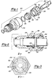
- Figure 1 illustrates a fluid coupling 20 for securing a tube 22 within a housing 24.
- a retainer 26 includes a forward ring 28 and a rear flex ring 30.
- a bore 29 is formed in forward ring 28.
- Retainer 26 has a conical outer surface to facilitate insertion into housing 24.
- a seal 34 and a steel seal retainer or spacer 36 are positioned in housing 24 axially inwardly of retainer 26. Seal retainer 36 has a flared axially outer end 38.
- a plurality of arms 32 abut upset portion 33 to prevent tube removal.
- Forward ring 28 abuts an axially outer end of flared outer end 38, and a generally conical inner portion 39 of forward ring 28 extends axially inwardly of flared outer end 38.
- Arms 32 have an inner peripheral surface which extends radially inwardly along a direction axially inwardly from flex ring 30. That is, the inner periphery of arms 32 is spaced from a centre axis X of housing 24 by a greater distance at an axial location adjacent flex ring 30 than it is spaced from the same axis at an axially inner end of arms 32.
- retainer 26 may move further axially inwardly for a relatively small amount until forward ring 28 contacts flared outer end 38 of seal retainer 36. Further axial movement of retainer 26 is now prevented. There is a small axial clearance between housing 24 and retainer 26 to allow for the axial movement of retainer 26, and the outward flexing of arms 32. As tube 22 continues to be inserted, upset portion 33 will cause arms 32 to flex radially outwardly approximately about a point 42 in rear flex ring 30. Upset portion 33 will eventually move axially beyond arms 32. Arm 32 flex back radially inwardly and tube 22 is fully connected within retainer 26.
- forward ring 28 positions retainer 26 by being forced against seal package 36, it is ensured that retainer 26 is properly orientated and positioned within housing 24. Further, since rear flex ring 30 connects each arm 32, it is ensured that the arms 32 are all properly axially positioned relative to the other, and that they all abut upset portion 33.
- Rear ring 30 is cylindrical and extends axially outwardly of an entrance bore 43 in housing 24. Arms 32 are spaced from an inner wall 44 that defines bore 43. Thus, rear ring 30 and arms 32 do not abut any portion of housing 24, or have a positioning function.
- Figure 3 is a view looking inwardly of housing 24 prior to the insertion of tube 22. As shown, arms 32 extend radially inwardly of bore 43 to housing 24. Rear flex ring 30 is received within bore 43, and bore 29 in forward ring 28 for receiving the axially inner end of tube 22 is positioned axially inwardly of bore 43.
- Figure 4 is a perspective view of plastic retainer 26. As shown, a plurality of webs 46 extend axially between forward ring 28 and rear flex ring 30, connecting the two. Arms 32 are integrally formed with rear ring 30, such that arms 32 flex about point 42. Arms 32 extend radially outwardly from the radially innermost portion of ring 30, and beyond the radially outermost portion of ring 30. Arms 32 are solid.
- webs 46 extend over a smaller circumferential extent at the radial inner portions than they do at radially outer portions.
- Arms 32 have a curved inner periphery such that they conform to the outer surface of tube 22.
- Figure 6 is a cross sectional view along line 6-6 as shown in Figure 4. Arms 32 extend radially beyond the radially outermost portion of rear flex ring 30, and then extend radially inwardly.
- the plastic retainer was formed of a material available under the trade mark CarilonTM, Code P1000, which is a product available from Shell Chemical. Its generic name is aliphatic polyketone, or APK.
Landscapes
- Engineering & Computer Science (AREA)
- General Engineering & Computer Science (AREA)
- Mechanical Engineering (AREA)
- Quick-Acting Or Multi-Walled Pipe Joints (AREA)
Abstract
Description
- This invention relates to a retainer that securely retains a tube within a housing.
- Various types of quick connect fluid couplings are known wherein a plastic retainer has two arms which extend radially inwardly to secure a radially greater upset portion of a tube within a housing bore. Generally, the upset portion of the tube is forced inwardly of the housing bore such that it causes the arms to flex radially outwardly. The upset portion then moves axially beyond the arms. The arms move back radially inwardly, and abut the upset portion, preventing tube removal.
- In this type of quick connect fluid coupling, several competing goals must be met. First, it is desirable that the arms securely retain the tube within the housing, and that a very high force be required to cause the retainer to fail and allow the tube to be removed. To this end, it is desirable to increase the number of arms which abut the upset portion of the tube.
- Merely increasing the number of arms is not a satisfactory solution, however, because it becomes difficult to ensure that the arms are all positioned at proper axial positions relative to each other. If the arms are misaligned they may not all abut the upset portion of the tube. Further, it becomes difficult to ensure that the retainer body is properly positioned within the housing bore. Because of these reasons the number of arms has typically been limited and plastic retainers have not been utilised in higher pressure connections.
- In a disclosed embodiment of the present invention a plastic retainer retains a tube within a housing bore. The retainer comprises a pair of axially spaced cylindrical rings with a plurality of circumferentially-spaced connecting webs extending between the two rings. Resilient arms are circumferentially-spaced between the webs, and extend from a rear flex ring. The arms abut the upset portion of a tube, and prevent tube removal.
- The tube is inserted into the bore, and eventually abuts the inner periphery of the arms. The retainer then moves axially forwardly for a relatively small distance until a forward ring abuts a seal package within the housing bore. The forward ring ensures that the retainer is properly orientated and positioned within the housing bore as the tube moves beyond the resilient arms. Further movement of the retainer is prevented, and the upset portion of the tube flexes the resilient arms radially outwardly about the rear flex ring, and moves axially beyond the arms. Since the arms flex at the rear flex ring, and are all interconnected by the rear flex ring, it is ensured that the arms are all properly positioned relative to each other. Thus, the arms all abut the upset portion, preventing tube removal and increasing the strength of the retainer. Due to the improved positioning of the retainer achieved by the spaced forward and rear rings, the inventive retainer can effectively use four arms. The retainer can thus be used in higher pressure applications.
- Most preferably, the rear flex ring extends for a relatively small radial extent compared to the radial thickness of the arms at a position connected to the rear ring. This improves the flexing of the arm relative to the rear ring. In a most preferred embodiment of the present invention the arm extends radially outwardly of the radially outermost portion of the rear flex ring.
- These and other objects and features of the present invention can be best understood from the following specification and drawings, of which the following is a brief description.
- Figure 1 is an exploded view of an inventive fluid coupling.
- Figure 2 is a cross-sectional view through an assembled coupling.
- Figure 3 is a partial end view of a coupling.
- Figure 4 is a perspective view of a retainer used in a fluid coupling.
- Figure 5 is an end view of the retainer illustrated in Figure 4; and
- Figure 6 is a cross-sectional view along line 6-6 as shown in Figure 4.
- Figure 1 illustrates a fluid coupling 20 for securing a
tube 22 within ahousing 24. Aretainer 26 includes aforward ring 28 and arear flex ring 30. Abore 29 is formed inforward ring 28. A plurality ofarms 32 entered fromflex ring 30 and abut a radially greater, orupset portion 33 oftube 22.Retainer 26 has a conical outer surface to facilitate insertion intohousing 24. Aseal 34 and a steel seal retainer orspacer 36 are positioned inhousing 24 axially inwardly ofretainer 26.Seal retainer 36 has a flared axiallyouter end 38. - As shown in Figure 2, a plurality of
arms 32 abutupset portion 33 to prevent tube removal.Forward ring 28 abuts an axially outer end of flaredouter end 38, and a generally conicalinner portion 39 offorward ring 28 extends axially inwardly of flaredouter end 38. - As
tube 22 is inserted withinhousing 24,upset portion 33 contacts an inner peripheral surface onarms 32.Arms 32 have an inner peripheral surface which extends radially inwardly along a direction axially inwardly fromflex ring 30. That is, the inner periphery ofarms 32 is spaced from a centre axis X ofhousing 24 by a greater distance at an axial locationadjacent flex ring 30 than it is spaced from the same axis at an axially inner end ofarms 32. - Once
upset portion 33 contacts the inner periphery ofarms 32,retainer 26 may move further axially inwardly for a relatively small amount untilforward ring 28 contacts flaredouter end 38 ofseal retainer 36. Further axial movement ofretainer 26 is now prevented. There is a small axial clearance betweenhousing 24 andretainer 26 to allow for the axial movement ofretainer 26, and the outward flexing ofarms 32. Astube 22 continues to be inserted,upset portion 33 will causearms 32 to flex radially outwardly approximately about apoint 42 inrear flex ring 30. Upsetportion 33 will eventually move axially beyondarms 32.Arm 32 flex back radially inwardly andtube 22 is fully connected withinretainer 26. - Since
forward ring 28positions retainer 26 by being forced againstseal package 36, it is ensured thatretainer 26 is properly orientated and positioned withinhousing 24. Further, sincerear flex ring 30 connects eacharm 32, it is ensured that thearms 32 are all properly axially positioned relative to the other, and that they all abutupset portion 33. -
Rear ring 30 is cylindrical and extends axially outwardly of anentrance bore 43 inhousing 24.Arms 32 are spaced from aninner wall 44 that definesbore 43. Thus,rear ring 30 andarms 32 do not abut any portion ofhousing 24, or have a positioning function. - Figure 3 is a view looking inwardly of
housing 24 prior to the insertion oftube 22. As shown,arms 32 extend radially inwardly ofbore 43 tohousing 24.Rear flex ring 30 is received withinbore 43, and bore 29 inforward ring 28 for receiving the axially inner end oftube 22 is positioned axially inwardly ofbore 43. - Figure 4 is a perspective view of
plastic retainer 26. As shown, a plurality ofwebs 46 extend axially betweenforward ring 28 andrear flex ring 30, connecting the two.Arms 32 are integrally formed withrear ring 30, such thatarms 32 flex aboutpoint 42.Arms 32 extend radially outwardly from the radially innermost portion ofring 30, and beyond the radially outermost portion ofring 30.Arms 32 are solid. - As shown in Figure 5,
webs 46 extend over a smaller circumferential extent at the radial inner portions than they do at radially outer portions.Arms 32 have a curved inner periphery such that they conform to the outer surface oftube 22. - Figure 6 is a cross sectional view along line 6-6 as shown in Figure 4.
Arms 32 extend radially beyond the radially outermost portion ofrear flex ring 30, and then extend radially inwardly. - In a most preferred embodiment of this invention, the plastic retainer was formed of a material available under the trade mark Carilon™, Code P1000, which is a product available from Shell Chemical. Its generic name is aliphatic polyketone, or APK.
- A preferred embodiment of the present invention has been disclosed, however, a worker of ordinary skill in the art would recognise that certain modifications would come within the scope of this invention. For that reason the following claims should be studied in order to determine the true scope and content of this invention.
Claims (8)
- A fluid coupling (20) comprising a housing (24) defining a bore with an axis extending inwardly into said bore from an entrance (43) to said bore and a seal package (36) positioned within said bore, characterised in that a retainer (26) having a cylindrical axially inner ring (28) at a first axial position, and a cylindrical axially outer ring (30) at a second axial position spaced axially outwardly from said first axial position, a plurality of arms (32) extending axially inwardly from said outer ring (30), said arms (32) having an inner periphery spaced by a greatest radial distance from said axis at a location adjacent said entrance (43) to said outer ring (30), and said arm inner periphery extending radially inwardly to an axially inner end spaced from said axis by a radial dimension that is less than said greatest radial dimension and a tube (22) received within said bore, said tube (22) being of a first outer diameter over the majority of an axial length, a greater diameter portion (33) being formed at one axial position of said tube (22), said greater diameter portion (33) being spaced axially inwardly of said arms (32) such that said arms (32) retain said tube (22) within said bore.
- A fluid coupling (20) according to claim 1, characterised in that said housing entrance (43) is of a first inner diameter at a position leading into said bore, said outer ring (30) having an outer diameter slightly less than said first diameter of said entrance (43), and said outer ring (30) extending axially outwardly of said entrance (43).
- A fluid coupling (20) according to claim 1 or 2, characterised in that a plurality of circumferentially, spaced webs (46) extend axially between said inner and outer rings (28,30) to connect the two.
- A fluid coupling (20) according to any one of the preceding claims, characterised in that there are at least four of said arms (32).
- A fluid coupling (20) according to any one of the preceding claims, characterised in that said retainer (26) is formed of a plastic material.
- A fluid coupling (20) according to claim 5, characterised in that said plastic material is an aliphatic polyketone.
- A fluid coupling (20) according to any one of the preceding claims, characterised in that said outer ring (30) is of a first radial thickness, and said arms (32) are of a greater radial thickness than said first radial thickness at a location axially adjacent said outer ring (30).
- A fluid connector (20) according to claim 7, characterised in that said arms (36) extend radially outwardly of a radially outermost portion of said outer ring (30) at said location axially adjacent to said outer ring (30).
Applications Claiming Priority (2)
| Application Number | Priority Date | Filing Date | Title |
|---|---|---|---|
| US777060 | 1985-09-17 | ||
| US07/777,060 US5161832A (en) | 1991-10-16 | 1991-10-16 | Plastic retainer for fluid coupling |
Publications (2)
| Publication Number | Publication Date |
|---|---|
| EP0537906A1 true EP0537906A1 (en) | 1993-04-21 |
| EP0537906B1 EP0537906B1 (en) | 1996-02-21 |
Family
ID=25109170
Family Applications (1)
| Application Number | Title | Priority Date | Filing Date |
|---|---|---|---|
| EP92308448A Expired - Lifetime EP0537906B1 (en) | 1991-10-16 | 1992-09-17 | Plastic retainer for fluid coupling |
Country Status (8)
| Country | Link |
|---|---|
| US (1) | US5161832A (en) |
| EP (1) | EP0537906B1 (en) |
| JP (1) | JPH05280680A (en) |
| BR (1) | BR9105641A (en) |
| CA (1) | CA2078174C (en) |
| DE (1) | DE69208416T2 (en) |
| ES (1) | ES2086081T3 (en) |
| MX (1) | MX9205835A (en) |
Cited By (1)
| Publication number | Priority date | Publication date | Assignee | Title |
|---|---|---|---|---|
| WO2006048070A1 (en) * | 2004-11-05 | 2006-05-11 | Veritas Ag | Coupling device for the connection of lines and motor vehicle with such a coupling device |
Families Citing this family (24)
| Publication number | Priority date | Publication date | Assignee | Title |
|---|---|---|---|---|
| US5626371A (en) * | 1990-01-16 | 1997-05-06 | Bartholomew; Donald D. | Quick connector with one-piece retainer |
| JPH0552284A (en) * | 1991-08-20 | 1993-03-02 | Usui Internatl Ind Co Ltd | Connector for connecting pipe of small diameter |
| EP0638157A4 (en) * | 1992-04-02 | 1995-05-03 | Proprietary Technology Inc | Quick connector with one-piece retainer. |
| GB9402758D0 (en) * | 1994-02-11 | 1994-04-06 | Guest John D | Improvements in or relating to tube couplings |
| US5568946A (en) * | 1994-12-14 | 1996-10-29 | Itt Corporation | Squeeze-to-release quick connector with snap-in retainer |
| JP2880453B2 (en) | 1996-06-07 | 1999-04-12 | 三桜工業株式会社 | Retainers for piping fittings |
| US6349977B1 (en) * | 1996-07-01 | 2002-02-26 | Ti Group Automotive Systems, L.L.C. | Quick connect retainer having tolerance for wide band of male tube dimensions |
| US5711553A (en) * | 1996-09-04 | 1998-01-27 | Stmc-Llc | Quick connect fluid coupling |
| US5707085A (en) * | 1996-09-12 | 1998-01-13 | General Motors Corporation | Fluid coupling |
| GB9620853D0 (en) | 1996-10-07 | 1996-11-27 | Rea International Inc | Connector assembly |
| US5873610A (en) * | 1996-12-19 | 1999-02-23 | Itt Automotive, Inc. | Female connector member for large tolerance male member endforms |
| US5897142A (en) * | 1996-12-19 | 1999-04-27 | Itt Automotive, Inc. | Push-to-release quick connector |
| GB9724521D0 (en) * | 1997-11-20 | 1998-01-21 | Munster Simms Engineering Limi | Pipe connections |
| US6193283B1 (en) | 1999-10-29 | 2001-02-27 | Automotive Fluid Systems, Inc. | Conduit and block connection indicator device |
| US7344166B2 (en) * | 2004-02-05 | 2008-03-18 | Ti Group Automotive Systems, Llc | Quick connector for high pressure applications |
| EP1561990B1 (en) * | 2004-02-05 | 2008-08-20 | TI Group Automotive Systems LLC | Quick connector for high pressure applications |
| US8113548B2 (en) * | 2005-06-30 | 2012-02-14 | Ti Group Automotive Systems, Llc | Quick connector for high pressure applications |
| DE102006062894B4 (en) * | 2005-06-30 | 2011-12-15 | Ti Group Automotive Systems, L.L.C. | protective cap |
| US7503784B2 (en) * | 2006-03-08 | 2009-03-17 | Ti Group Automotive Systems, Llc | Quick connector |
| JP5024856B2 (en) * | 2006-05-09 | 2012-09-12 | 臼井国際産業株式会社 | Connector for small diameter pipe connection |
| US8297659B2 (en) | 2011-02-22 | 2012-10-30 | Miniature Precision Components, Inc. | Quick connector assembly |
| US20120247179A1 (en) | 2011-04-01 | 2012-10-04 | Ti Group Automotive Systems, Llc | Sensor housing and latching mechanism for sensor housing |
| US20160025252A1 (en) * | 2014-07-23 | 2016-01-28 | Paccar Inc | Quick fitting connector |
| FR3029594B1 (en) * | 2014-12-03 | 2017-06-02 | Parker Hannifin Mfg France Sas | CARTRIDGE TYPE CONNECTION DEVICE, WITH ANCHOR TUBULAR SECTIONS AND METHOD OF MANUFACTURE |
Citations (3)
| Publication number | Priority date | Publication date | Assignee | Title |
|---|---|---|---|---|
| AT388426B (en) * | 1984-06-05 | 1989-06-26 | Bartholomew Donald Dekle | COUPLING ARRANGEMENT FOR AT LEAST ONE PIPELINE AND SEALING PLUG FOR |
| GB2216213A (en) * | 1988-03-01 | 1989-10-04 | Usui Kokusai Sangyo Kk | Pipe coupling with means for indicating correct connection |
| WO1989009361A1 (en) * | 1988-03-30 | 1989-10-05 | Itt Automotive, Inc. | Quick connector assembly |
Family Cites Families (11)
| Publication number | Priority date | Publication date | Assignee | Title |
|---|---|---|---|---|
| US2441344A (en) * | 1945-05-14 | 1948-05-11 | Weatherhead Co | Coupling |
| US3711125A (en) * | 1971-06-29 | 1973-01-16 | Ford Motor Co | Quick connect fitting for a hydraulic conduit |
| BE788517A (en) * | 1971-09-07 | 1973-03-07 | Raychem Corp | VERY LOW TEMPERATURE CHUCK EXPANSION PROCESS |
| US5009454A (en) * | 1980-10-29 | 1991-04-23 | Proprietary Technology, Inc. | Swivelable quick connector assembly |
| US4944536A (en) * | 1980-10-29 | 1990-07-31 | Proprietary Technology, Inc. | Bleed-down connector assembly |
| US4524995A (en) * | 1980-10-29 | 1985-06-25 | Proprietary Technology, Inc. | Swivelable quick connector assembly |
| US4681351A (en) * | 1982-03-22 | 1987-07-21 | Proprietary Technology, Inc. | Swivelable quick connector assembly |
| US4610468A (en) * | 1984-08-14 | 1986-09-09 | United Technologies Automotive, Inc. | Quick connect/disconnect coupling |
| US5002315A (en) * | 1988-04-07 | 1991-03-26 | Proprietary Technology, Inc. | Quick connector |
| US4964658A (en) * | 1988-07-29 | 1990-10-23 | Usui Kokusai Sangyo Kaisha Ltd. | Small-size piping coupling joint |
| US4890866A (en) * | 1989-03-14 | 1990-01-02 | Mentor Corporation | Tubing connector |
-
1991
- 1991-10-16 US US07/777,060 patent/US5161832A/en not_active Expired - Lifetime
- 1991-12-30 BR BR919105641A patent/BR9105641A/en not_active IP Right Cessation
-
1992
- 1992-09-14 CA CA002078174A patent/CA2078174C/en not_active Expired - Fee Related
- 1992-09-17 ES ES92308448T patent/ES2086081T3/en not_active Expired - Lifetime
- 1992-09-17 EP EP92308448A patent/EP0537906B1/en not_active Expired - Lifetime
- 1992-09-17 DE DE69208416T patent/DE69208416T2/en not_active Expired - Lifetime
- 1992-10-09 MX MX9205835A patent/MX9205835A/en not_active IP Right Cessation
- 1992-10-15 JP JP4277027A patent/JPH05280680A/en active Pending
Patent Citations (3)
| Publication number | Priority date | Publication date | Assignee | Title |
|---|---|---|---|---|
| AT388426B (en) * | 1984-06-05 | 1989-06-26 | Bartholomew Donald Dekle | COUPLING ARRANGEMENT FOR AT LEAST ONE PIPELINE AND SEALING PLUG FOR |
| GB2216213A (en) * | 1988-03-01 | 1989-10-04 | Usui Kokusai Sangyo Kk | Pipe coupling with means for indicating correct connection |
| WO1989009361A1 (en) * | 1988-03-30 | 1989-10-05 | Itt Automotive, Inc. | Quick connector assembly |
Cited By (1)
| Publication number | Priority date | Publication date | Assignee | Title |
|---|---|---|---|---|
| WO2006048070A1 (en) * | 2004-11-05 | 2006-05-11 | Veritas Ag | Coupling device for the connection of lines and motor vehicle with such a coupling device |
Also Published As
| Publication number | Publication date |
|---|---|
| CA2078174C (en) | 2000-01-11 |
| JPH05280680A (en) | 1993-10-26 |
| DE69208416T2 (en) | 1996-07-04 |
| CA2078174A1 (en) | 1993-04-17 |
| ES2086081T3 (en) | 1996-06-16 |
| MX9205835A (en) | 1993-06-01 |
| EP0537906B1 (en) | 1996-02-21 |
| US5161832A (en) | 1992-11-10 |
| BR9105641A (en) | 1993-04-27 |
| DE69208416D1 (en) | 1996-03-28 |
Similar Documents
| Publication | Publication Date | Title |
|---|---|---|
| US5161832A (en) | Plastic retainer for fluid coupling | |
| US6343814B1 (en) | Insertion verifier dust cap | |
| US5257833A (en) | Metal retainer for quick connect tubing connector | |
| US7467813B2 (en) | Quick connector | |
| EP0529758B1 (en) | Quick connect coupling | |
| EP0532242B1 (en) | Quick connect tubing connector | |
| US5813705A (en) | Snap-action pipe coupling retainer | |
| EP0459016B1 (en) | Quick connector | |
| US7891380B2 (en) | Protective cap for quick connector | |
| US11131411B2 (en) | Fluid connection device | |
| US4929002A (en) | Device for coupling a hose to a pipe | |
| US5324082A (en) | Positive transition quick connect coupling | |
| US5423577A (en) | Tubing connector | |
| US5228728A (en) | Tube retainer release sleeve | |
| EP0803039B1 (en) | Quick connect fluid coupling with collet retainer | |
| US5538297A (en) | Quick connect tubing connector | |
| US6086118A (en) | Quick connect tubing connector | |
| US5009454A (en) | Swivelable quick connector assembly | |
| US6186561B1 (en) | Retainer for piping connector | |
| JPH08270861A (en) | Quick connector fittings | |
| EP0112015B1 (en) | Couplings for tubes and other fluid handling components | |
| EP0294948A2 (en) | Socket assembly | |
| CA2300728A1 (en) | A push fit attachment | |
| WO1993015349A1 (en) | Tubing connector | |
| JP7419162B2 (en) | Hose connector and plug members that make up the hose connector |
Legal Events
| Date | Code | Title | Description |
|---|---|---|---|
| PUAI | Public reference made under article 153(3) epc to a published international application that has entered the european phase |
Free format text: ORIGINAL CODE: 0009012 |
|
| AK | Designated contracting states |
Kind code of ref document: A1 Designated state(s): BE DE ES FR GB IT NL PT SE |
|
| 17P | Request for examination filed |
Effective date: 19930617 |
|
| RAP1 | Party data changed (applicant data changed or rights of an application transferred) |
Owner name: BUNDY CORPORATION |
|
| 17Q | First examination report despatched |
Effective date: 19941108 |
|
| GRAA | (expected) grant |
Free format text: ORIGINAL CODE: 0009210 |
|
| AK | Designated contracting states |
Kind code of ref document: B1 Designated state(s): BE DE ES FR GB IT NL PT SE |
|
| REF | Corresponds to: |
Ref document number: 69208416 Country of ref document: DE Date of ref document: 19960328 |
|
| ITF | It: translation for a ep patent filed | ||
| ET | Fr: translation filed | ||
| REG | Reference to a national code |
Ref country code: ES Ref legal event code: FG2A Ref document number: 2086081 Country of ref document: ES Kind code of ref document: T3 |
|
| SC4A | Pt: translation is available |
Free format text: 960424 AVAILABILITY OF NATIONAL TRANSLATION |
|
| PG25 | Lapsed in a contracting state [announced via postgrant information from national office to epo] |
Ref country code: GB Effective date: 19960917 |
|
| PG25 | Lapsed in a contracting state [announced via postgrant information from national office to epo] |
Ref country code: SE Effective date: 19960918 |
|
| PG25 | Lapsed in a contracting state [announced via postgrant information from national office to epo] |
Ref country code: BE Effective date: 19960930 |
|
| PLBE | No opposition filed within time limit |
Free format text: ORIGINAL CODE: 0009261 |
|
| 26N | No opposition filed | ||
| BERE | Be: lapsed |
Owner name: BUNDY CORP. Effective date: 19960930 |
|
| PG25 | Lapsed in a contracting state [announced via postgrant information from national office to epo] |
Ref country code: NL Effective date: 19970401 |
|
| GBPC | Gb: european patent ceased through non-payment of renewal fee |
Effective date: 19960917 |
|
| NLV4 | Nl: lapsed or anulled due to non-payment of the annual fee |
Effective date: 19970401 |
|
| EUG | Se: european patent has lapsed |
Ref document number: 92308448.7 |
|
| PG25 | Lapsed in a contracting state [announced via postgrant information from national office to epo] |
Ref country code: PT Free format text: LAPSE BECAUSE OF NON-PAYMENT OF DUE FEES Effective date: 19980331 |
|
| REG | Reference to a national code |
Ref country code: PT Ref legal event code: MM4A Free format text: LAPSE DUE TO NON-PAYMENT OF FEES Effective date: 19980331 |
|
| PG25 | Lapsed in a contracting state [announced via postgrant information from national office to epo] |
Ref country code: IT Free format text: LAPSE BECAUSE OF NON-PAYMENT OF DUE FEES;WARNING: LAPSES OF ITALIAN PATENTS WITH EFFECTIVE DATE BEFORE 2007 MAY HAVE OCCURRED AT ANY TIME BEFORE 2007. THE CORRECT EFFECTIVE DATE MAY BE DIFFERENT FROM THE ONE RECORDED. Effective date: 20050917 |
|
| PG25 | Lapsed in a contracting state [announced via postgrant information from national office to epo] |
Ref country code: PT Free format text: LAPSE BECAUSE OF NON-PAYMENT OF DUE FEES Effective date: 19960917 |
|
| PGFP | Annual fee paid to national office [announced via postgrant information from national office to epo] |
Ref country code: DE Payment date: 20100929 Year of fee payment: 19 |
|
| PGFP | Annual fee paid to national office [announced via postgrant information from national office to epo] |
Ref country code: FR Payment date: 20111005 Year of fee payment: 20 Ref country code: ES Payment date: 20110926 Year of fee payment: 20 |
|
| REG | Reference to a national code |
Ref country code: DE Ref legal event code: R071 Ref document number: 69208416 Country of ref document: DE |
|
| REG | Reference to a national code |
Ref country code: DE Ref legal event code: R071 Ref document number: 69208416 Country of ref document: DE |
|
| PG25 | Lapsed in a contracting state [announced via postgrant information from national office to epo] |
Ref country code: DE Free format text: LAPSE BECAUSE OF EXPIRATION OF PROTECTION Effective date: 20120918 |
|
| REG | Reference to a national code |
Ref country code: ES Ref legal event code: FD2A Effective date: 20130801 |
|
| PG25 | Lapsed in a contracting state [announced via postgrant information from national office to epo] |
Ref country code: ES Free format text: LAPSE BECAUSE OF EXPIRATION OF PROTECTION Effective date: 20120918 |