EP1806182A1 - Electrically-conductive plastic hangers - Google Patents
Electrically-conductive plastic hangers Download PDFInfo
- Publication number
- EP1806182A1 EP1806182A1 EP07000347A EP07000347A EP1806182A1 EP 1806182 A1 EP1806182 A1 EP 1806182A1 EP 07000347 A EP07000347 A EP 07000347A EP 07000347 A EP07000347 A EP 07000347A EP 1806182 A1 EP1806182 A1 EP 1806182A1
- Authority
- EP
- European Patent Office
- Prior art keywords
- hanger
- workpiece
- coating
- hangers
- conductive
- Prior art date
- Legal status (The legal status is an assumption and is not a legal conclusion. Google has not performed a legal analysis and makes no representation as to the accuracy of the status listed.)
- Withdrawn
Links
- 239000004033 plastic Substances 0.000 title claims abstract description 80
- 229920003023 plastic Polymers 0.000 title claims abstract description 80
- 239000000463 material Substances 0.000 claims abstract description 79
- 238000000576 coating method Methods 0.000 claims description 109
- 239000011248 coating agent Substances 0.000 claims description 91
- 238000000034 method Methods 0.000 claims description 32
- 239000004020 conductor Substances 0.000 claims description 22
- 239000000843 powder Substances 0.000 claims description 14
- 230000000873 masking effect Effects 0.000 claims description 11
- 239000004696 Poly ether ether ketone Substances 0.000 claims description 5
- 239000004734 Polyphenylene sulfide Substances 0.000 claims description 5
- 229920002530 polyetherether ketone Polymers 0.000 claims description 5
- 229920000069 polyphenylene sulfide Polymers 0.000 claims description 5
- -1 polyethylenes Polymers 0.000 claims description 4
- 229920000049 Carbon (fiber) Polymers 0.000 claims description 3
- 229920000106 Liquid crystal polymer Polymers 0.000 claims description 3
- 239000004977 Liquid-crystal polymers (LCPs) Substances 0.000 claims description 3
- 229920002302 Nylon 6,6 Polymers 0.000 claims description 3
- 239000004698 Polyethylene Substances 0.000 claims description 3
- 239000004917 carbon fiber Substances 0.000 claims description 3
- 229920000573 polyethylene Polymers 0.000 claims description 3
- OKTJSMMVPCPJKN-UHFFFAOYSA-N Carbon Chemical compound [C] OKTJSMMVPCPJKN-UHFFFAOYSA-N 0.000 claims description 2
- RYGMFSIKBFXOCR-UHFFFAOYSA-N Copper Chemical compound [Cu] RYGMFSIKBFXOCR-UHFFFAOYSA-N 0.000 claims description 2
- 229910052782 aluminium Inorganic materials 0.000 claims description 2
- XAGFODPZIPBFFR-UHFFFAOYSA-N aluminium Chemical compound [Al] XAGFODPZIPBFFR-UHFFFAOYSA-N 0.000 claims description 2
- 229910052799 carbon Inorganic materials 0.000 claims description 2
- 239000006229 carbon black Substances 0.000 claims description 2
- 229910052802 copper Inorganic materials 0.000 claims description 2
- 239000010949 copper Substances 0.000 claims description 2
- 239000003365 glass fiber Substances 0.000 claims description 2
- PCHJSUWPFVWCPO-UHFFFAOYSA-N gold Chemical compound [Au] PCHJSUWPFVWCPO-UHFFFAOYSA-N 0.000 claims description 2
- 229910052737 gold Inorganic materials 0.000 claims description 2
- 239000010931 gold Substances 0.000 claims description 2
- QXJJQWWVWRCVQT-UHFFFAOYSA-K calcium;sodium;phosphate Chemical compound [Na+].[Ca+2].[O-]P([O-])([O-])=O QXJJQWWVWRCVQT-UHFFFAOYSA-K 0.000 claims 1
- 238000009503 electrostatic coating Methods 0.000 abstract description 3
- 238000007747 plating Methods 0.000 abstract 1
- 238000004140 cleaning Methods 0.000 description 14
- 229910052751 metal Inorganic materials 0.000 description 11
- 239000002184 metal Substances 0.000 description 11
- 239000002245 particle Substances 0.000 description 8
- 239000007921 spray Substances 0.000 description 7
- 239000000543 intermediate Substances 0.000 description 6
- 238000004519 manufacturing process Methods 0.000 description 5
- 239000000243 solution Substances 0.000 description 5
- 239000012815 thermoplastic material Substances 0.000 description 5
- 238000001746 injection moulding Methods 0.000 description 4
- 230000007246 mechanism Effects 0.000 description 4
- 239000000126 substance Substances 0.000 description 3
- 239000002253 acid Substances 0.000 description 2
- 150000007513 acids Chemical class 0.000 description 2
- 238000007743 anodising Methods 0.000 description 2
- 230000015572 biosynthetic process Effects 0.000 description 2
- 238000007600 charging Methods 0.000 description 2
- 239000003795 chemical substances by application Substances 0.000 description 2
- 238000000748 compression moulding Methods 0.000 description 2
- 238000001816 cooling Methods 0.000 description 2
- 238000009826 distribution Methods 0.000 description 2
- 238000009713 electroplating Methods 0.000 description 2
- 239000012634 fragment Substances 0.000 description 2
- 239000007789 gas Substances 0.000 description 2
- 238000007654 immersion Methods 0.000 description 2
- 238000010102 injection blow moulding Methods 0.000 description 2
- 239000007788 liquid Substances 0.000 description 2
- 150000002739 metals Chemical class 0.000 description 2
- 238000000465 moulding Methods 0.000 description 2
- 239000003973 paint Substances 0.000 description 2
- 239000013618 particulate matter Substances 0.000 description 2
- 229920001296 polysiloxane Polymers 0.000 description 2
- 229920001169 thermoplastic Polymers 0.000 description 2
- 239000004416 thermosoftening plastic Substances 0.000 description 2
- JOYRKODLDBILNP-UHFFFAOYSA-N Ethyl urethane Chemical compound CCOC(N)=O JOYRKODLDBILNP-UHFFFAOYSA-N 0.000 description 1
- 229910000831 Steel Inorganic materials 0.000 description 1
- 229920004695 VICTREX™ PEEK Polymers 0.000 description 1
- NIXOWILDQLNWCW-UHFFFAOYSA-N acrylic acid group Chemical group C(C=C)(=O)O NIXOWILDQLNWCW-UHFFFAOYSA-N 0.000 description 1
- 238000005452 bending Methods 0.000 description 1
- JUPQTSLXMOCDHR-UHFFFAOYSA-N benzene-1,4-diol;bis(4-fluorophenyl)methanone Chemical compound OC1=CC=C(O)C=C1.C1=CC(F)=CC=C1C(=O)C1=CC=C(F)C=C1 JUPQTSLXMOCDHR-UHFFFAOYSA-N 0.000 description 1
- 238000005520 cutting process Methods 0.000 description 1
- 230000002950 deficient Effects 0.000 description 1
- 229910003460 diamond Inorganic materials 0.000 description 1
- 239000010432 diamond Substances 0.000 description 1
- 238000003618 dip coating Methods 0.000 description 1
- 230000000694 effects Effects 0.000 description 1
- 230000005611 electricity Effects 0.000 description 1
- 238000004070 electrodeposition Methods 0.000 description 1
- 238000007786 electrostatic charging Methods 0.000 description 1
- 230000007613 environmental effect Effects 0.000 description 1
- 238000005530 etching Methods 0.000 description 1
- 239000000835 fiber Substances 0.000 description 1
- 230000009969 flowable effect Effects 0.000 description 1
- 239000003517 fume Substances 0.000 description 1
- 239000008187 granular material Substances 0.000 description 1
- 238000010438 heat treatment Methods 0.000 description 1
- 230000001788 irregular Effects 0.000 description 1
- 239000011159 matrix material Substances 0.000 description 1
- 239000007769 metal material Substances 0.000 description 1
- VNWKTOKETHGBQD-UHFFFAOYSA-N methane Chemical compound C VNWKTOKETHGBQD-UHFFFAOYSA-N 0.000 description 1
- 239000000203 mixture Substances 0.000 description 1
- 229920000728 polyester Polymers 0.000 description 1
- 238000004064 recycling Methods 0.000 description 1
- 238000007789 sealing Methods 0.000 description 1
- 238000000926 separation method Methods 0.000 description 1
- 239000004447 silicone coating Substances 0.000 description 1
- 239000007787 solid Substances 0.000 description 1
- 229910001220 stainless steel Inorganic materials 0.000 description 1
- 239000010935 stainless steel Substances 0.000 description 1
- 230000003068 static effect Effects 0.000 description 1
- 239000010959 steel Substances 0.000 description 1
- 238000004381 surface treatment Methods 0.000 description 1
- 231100000331 toxic Toxicity 0.000 description 1
- 230000002588 toxic effect Effects 0.000 description 1
- 239000002699 waste material Substances 0.000 description 1
Images




Classifications
-
- B—PERFORMING OPERATIONS; TRANSPORTING
- B05—SPRAYING OR ATOMISING IN GENERAL; APPLYING FLUENT MATERIALS TO SURFACES, IN GENERAL
- B05B—SPRAYING APPARATUS; ATOMISING APPARATUS; NOZZLES
- B05B5/00—Electrostatic spraying apparatus; Spraying apparatus with means for charging the spray electrically; Apparatus for spraying liquids or other fluent materials by other electric means
- B05B5/08—Plant for applying liquids or other fluent materials to objects
- B05B5/082—Plant for applying liquids or other fluent materials to objects characterised by means for supporting, holding or conveying the objects
-
- C—CHEMISTRY; METALLURGY
- C25—ELECTROLYTIC OR ELECTROPHORETIC PROCESSES; APPARATUS THEREFOR
- C25D—PROCESSES FOR THE ELECTROLYTIC OR ELECTROPHORETIC PRODUCTION OF COATINGS; ELECTROFORMING; APPARATUS THEREFOR
- C25D17/00—Constructional parts, or assemblies thereof, of cells for electrolytic coating
- C25D17/06—Suspending or supporting devices for articles to be coated
Definitions
- the field of the invention is supports and, more particularly, electrically-conductive hangers for supporting one or more workpieces in coating and other processing operations.
- Powder coating and electro-deposition coating (“E-coating”) processes are representative processes in which it is desirable to both support and ground the workpiece in order to optimally perform the process.
- electrostatically charged powdered paint (usually a form of finely ground plastic particles) is deposited onto the workpiece by, for example, spray application in a spray booth.
- Each workpiece may be delivered to the spray booth by a coating line conveyor. In other operations, the workpiece may simply be manually suspended from a hook, rack or like support within the spray booth.
- Each workpiece is typically suspended from the conveyor or from a hook or rack in the coating booth by means of a hanger so that the workpiece surfaces are exposed to the coating material and so that the coating material may be deposited on such surfaces.
- the hanger is typically made of an electrically-conductive metal material so that the workpiece can be electrostatically charged, typically by grounding.
- Hangers are available in many shapes and forms, including small individual wire hooks, supports, or large welded racks with multiple hanging points.
- Conventional individual hooks typically have a generally C-shaped appearance.
- Conventional large welded racks may comprise a "frame" having dimensions of about 60 cm by 90 cm with end members and cross bars suspended across it. Each cross bar will contain 20 to 100 small hooks or posts welded to it. These racks are time consuming and costly to manufacture because many separate welds are required.
- Materials used in hanger manufacture include standard or stainless steel. High-temperature-resistant metals are desirable because such metals can withstand the high temperatures used to remove or "burn off' excess coating during cleaning of the hangers. Such temperatures can exceed 540°C.
- coating particles may be electrostatically charged such that the particles have a charge which is opposite of the charge on the workpiece.
- the charge may be imparted with either a corona gun or Tribo gun, each of which ionize the coating particles.
- the devices work quite differently, but the end result is the same in that a cloud of ionized coating is produced about the workpiece surfaces.
- the electrostatically charged particles are attracted to the oppositely charged workpiece by natural static electricity.
- the coating particles attach to any oppositely charged article, including the workpiece and the grounding hanger or hook.
- the electrostatic charge attraction carries the coating until the workpiece and supporting hanger reach the curing oven.
- the coating is cured at an average temperature of about 205°C or lower for approximately 30 minutes. Times and temperatures vary depending on the type of powder coating material utilized.
- Typical powder coating paints are thermoplastic materials and consist of powdered forms of polyester, urethane, acrylic and other materials.
- the heated coating partially liquefies and then cures to form an extremely durable and strong film on the workpiece surfaces.
- the cured coating is almost impossible to remove once cured and will remain intact at temperatures of up to about 510°C if the workpiece was properly cleaned before the coating operation.
- the coating material cures not just on the workpiece but on the hanger which supports the workpiece during the curing process.
- the coated workpiece is removed from the hanger and is processed further if desired.
- the hanger is then recycled for use in subsequent coating cycles. Because conventional metal hooks, hangers and racks are relatively costly, it is advantageous to reuse these types of supports as many times as possible to minimize cost to the operator.
- the workpiece to be coated, treated or processed is initially mounted on a hanger, such as a hook, rack or other support.
- the workpiece is electrostatically charged (e.g. grounded) through contact with the hanger.
- the workpiece is then immersed or dipped in a liquid-containing submersion tank or vessel.
- the submersion tank contains ionized coating particles having a charge which is opposite that of the workpiece, much like the powder coating process described above.
- the coating is deposited onto the workpiece surfaces by charge attraction.
- the end result of an E-coating process is similar to that of powder coating, but typically creates a thinner, more consistent coating provided that the workpiece surfaces can be suitably accessed by the coating or other material.
- E-coating processes may require that the workpiece surfaces be pre-treated before application of the coating.
- One or more separate submersion tanks may be provided for this purpose, each including mild acids to etch and clean the workpieces prior to coating.
- Proper treatment of the workpiece surfaces, either by treatment before application of the coating, or with the coating itself requires that the surfaces be freely accessible.
- the hanger is typically reused after the coated workpiece is removed from the hanger.
- the coating material is attracted to anything which has an opposite electrostatic charge, including the hanger.
- the coating itself is non-conductive. After one or two coating cycles, the contact point between the hanger and the workpiece supported by the hanger receives a thin insulating layer of the coating material. This insulating layer of coating material interferes with electrostatic charging of the workpiece such that the coating material is not properly attracted to the workpiece surfaces. As a result, the coated workpiece may be defective or excessive amounts of coating material may be required to coat the workpiece thereby imposing undesired costs on the operator.
- the typical (i.e., least expensive) cleaning method is to burn the excess coating off the hanger in a burn-off oven.
- the burn-off oven generates temperatures of about 540°C. This heat turns the coating to ash which crumbles off of the hanger.
- This cleaning process is not optimal, however, because the ash may contain potentially toxic materials thereby creating disposal problems and further because the burn-off process generates unwanted fumes and off-gases.
- Vibratory cleaning involves violent shaking of the hangers such that the coating starts to chip or break off of the hanger. Vibratory cleaning can damage the hangers. And, vibratory cleaning is not an optimal cleaning technique because it does not fully remove coating from the hangers thereby leaving coating fragments attached to the hangers. These fragments are known to slough off of the hangers during subsequent coating cycles potentially contaminating the workpieces and the operator's facility as the hangers are re-used in subsequent coating cycles.
- each of these hanger-cleaning processes involve added labor and material costs to the coating process. While these costs can be avoided by simply discarding the hangers after one use, it is apparent that discarding of the metal hangers after a single use imposes still other costs on the operator.
- electrically-conductive plastic hangers may be implemented for supporting a workpiece during electrostatic coating, treating or other workpiece-processing operations.
- Hangers as described herein can be manufactured in a wide range of shapes, sizes, configurations and materials to meet the needs of the operator.
- the hangers are provided with a one-piece hanger body made of an electrically-conductive plastic material.
- the body includes a connector portion configured to hang the body from a rack or other support and a connector portion capable of hanging a workpiece from the hanger body. It is preferred that the body is made entirely of the plastic material. It is envisioned, however, that other conductive and non-conductive parts, such as an appendage for gripping the hanger, may be associated with the electrically-conductive hanger body.
- Electrically-conductive plastic materials suitable for use in making the hangers comprise one plastic material or plural plastic materials in combination with one conductive material or plural conductive materials.
- the materials selected for use in making the hangers should as a whole provide sufficient conductivity to permit the desired electrostatic state or charge to be imparted to the workpiece.
- the workpiece will be grounded. However, it is to be understood that any desired state may be imparted to the workpiece through the hanger.
- the materials are selected so that the hanger is capable of withstanding temperatures of up to about 235°C. Preferably, the materials can be exposed to this temperature range for about 30 minutes without deformation.
- Hangers may, of course, be used in applications in which elevated temperatures are not involved and such hangers may be made of any suitable material or materials.
- the connector portions comprise a first connector portion which includes one or more hooks used to support the hanger from a rack or other support or conveyance. It is further preferred that a second connector portion comprises one or more hooks used to suspend a workpiece from the hanger.
- the connector portions may take on configurations other than hooks. Examples are spiral or helical configuration connectors, snap hook mechanisms or locking hook mechanisms.
- Hangers may be made according to many different manufacturing processes. Preferred representative processes include injection molding, blow molding and compression molding. An advantage of molding processes is that the hangers can be mass produced at cost which is a fraction of the cost of conventional metal hangers thereby enabling the operator to discard the hangers at the end of the coating cycle.
- Hanger 10 is of the type used to support a workpiece 11 from the hook 13 of a rack, support or conveyance (not shown) during electrostatic coating, treating or processing of the workpiece 11.
- hook 13 and its rack, support or conveyance are grounded or otherwise electrostatically charged.
- Hanger 10 serves as an electrical conductor permitting the operator to impart a desired electrostatic state or charge to workpiece 11 so that oppositely charged coatings and other materials will be attracted onto workpiece 11.
- hanger 10 and workpiece 11 are placed in a grounded electrostatic state.
- hangers as described herein may be utilized to impart any desired charge or state to workpiece 11 so that the coating or other material is attracted to workpiece 11.
- the supported electrostatically charged workpiece 11 may be coated, treated or processed.
- treatment or processing is performed in a spray booth, submersible tank, or other apparatus adapted to apply coating or other desired material to workpiece 11.
- Such operations may include any of those known to persons of skill in the art and include, without limitation, powder coating, E-coating, electro-plating, anodizing, application of autoferretic coatings as well as cleaning, etching and other forms of surface treatment.
- Plastic as used to characterize hanger 10 and the other hanger embodiments described herein is intended to be a broad term which means or refers to any of the numerous organic, synthetic or processed polymeric materials that can be molded, cast, extruded, drawn or otherwise made into objects such as hangers.
- an "electrically-conductive plastic material” means or refers to a material which comprises a plastic component and a conductive component.
- the plastic component may comprise one plastic material or plural plastic materials.
- the conductive component may comprise one conductive material or plural conductive materials.
- the plastic and conductive materials may be associated by any suitable means including, for example, by embedding conductive material in the plastic. Embedding, or to embed, means or refers to making conductive material an integral part of the plastic, for example, embedding conductive particles in a plastic matrix.
- hanger means or refers to any hook, support, rack, stand, framework or other contrivance from which a workpiece is hung, held or otherwise supported.
- a hanger may simultaneously support plural workpieces.
- Electrostatic means or refers to a process involving the use of electrical charge to produce attraction of the coating or other material to workpiece 11.
- hanger 10 shown therein has a one-piece, unitary hanger body 15 which includes first and second connector portions 17, 19. As illustrated in Figure 1, first connector portion 17 is preferably configured to hang body 15 from hook 13 or other support and second connector portion 19 is preferably configured to directly support workpiece 11.
- body 15 is a generally C-shaped member with first and second connector portions 17, 19 respectively forming upper and lower hooks. As shown in Figure 3, body 15 preferably has a rounded shape in section. In the preferred embodiment 10, hanger body 15, including connector portions 17, 19, lies generally in a plane.
- Body 15 is made of electrically-conductive plastic material. Most preferably, body 15 is made entirely of such plastic material. Other conductive or non-conductive parts, such as a gripping appendage or an auxiliary hook (not shown), may be associated with the electrically-conductive hanger body 15.
- a preferred electrically-conductive plastic may comprise plastic component 21 and conductive component 23 embedded therein to impart the electrical conductivity.
- Plastic component 21 preferably comprises a thermoplastic material.
- Representative thermoplastic materials include polyether ether ketones, polyphenylene sulfides, polyethylenes, liquid crystal polymers, and nylon 6-6. Any plastic material will suffice provided that the material can support hanger 10 from a support such as hook 13 and can support a workpiece 11.
- Conductive component 23 is selected so as to provide the desired conductivity. Conductive component 23 should be distributed throughout plastic component 21 such that conductive component 23 is dispersed or distributed in a generally uniform, or homogenous, manner within body 15. The "homogenous" dispersal or distribution of conductive material 23 means only that conductive material 23 is dispersed or distributed sufficiently within body 15 such that hanger 10 can conduct the desired electrical charge. As shown in Figure 3, in any given portion of hanger 10, conductive material 23 can and likely will be distributed in an irregular manner within plastic material 21.
- Conductive component 23 includes metallic powders, carbon black, carbon fibers, carbon mats, and metallized glass fibers and spheres. Copper, aluminum, gold, and other conductive materials may be utilized. Mixtures of the conductive materials may be utilized. Conductive material 23 may be in any form permitting generally uniform or homogenous distribution throughout plastic material 21 comprising body 15. Examples are powders, flakes, granules and fibers. As shown in Figure 3, conductive material 23 can comprise conductive materials of varying sizes including, for example, large and relatively smaller materials.
- Conductive component 23 may be associated with plastic component 21 in any suitable manner.
- conductive component 23 may be in flake or powder form and may be admixed with a granular-form plastic component 21 at any time before formation of body 15. Upon formation of body 15, conductive material 23 would be distributed or embedded within plastic component 21.
- thermoplastic polyether ether ketones are sold under the trademark PEEK by Victrex USA, Inc. of Greenville, South Carolina and representative thermoplastic polyphenylene sulfides are marketed under the trade name Techtron® PPS by Boedeker Plastics, Inc. of Shiner, Texas.
- Techtron® PPS by Boedeker Plastics, Inc. of Shiner, Texas.
- Each of these representative plastic component 21 materials can be made electrically conductive by adding a 30% carbon fiber component 23 to plastic component 21.
- conductive component 23 must be present in sufficient amount to serve as a conductor. It is expected that the specific amount of conductive component 23 utilized will vary based on factors such as the plastic material 21 selected and the requirements of the operator. It is possible to adjust the relative amount of conductive material 23 in hanger body 15 to control the amount of conductivity. Preferably, the material or materials selected for components 21, 23 are such that hanger 10 has a very low resistance thereby facilitating charging or grounding of the workpiece supported by hanger 10. It is preferred that hanger 10 has a resistance of less than about 1 M ⁇ with a resistance of less than about 0.1 M ⁇ being more preferred.
- the plastic component 21 should preferably be selected such that hanger 10 is capable of withstanding temperatures up to about 235°C. Preferably, the plastic component 21 materials can be exposed to this temperature range for about 30 minutes without deformation. Without deformation means that the hanger 10 substantially retains its configuration. Hangers such as hanger 10 are intended to be utilized in many different applications including those in which the hanger 10 and workpiece 11 are not exposed to elevated temperatures. Hangers for use in such applications may be made of any suitable plastic component 21 material.
- Hanger 10 is most preferably the product of conventional plastic forming processes known to persons of skill in the art.
- Hanger 10 may be formed, for example, by injection molding, blow molding and compression molding.
- the product of such a forming process is a body 15 and connector portions 17, 19 which are formed integrally as a one-piece, unitary part.
- Injection molding is a particularly preferred process by which to form hanger 10 because of the ease of preparing the components 21, 23 and forming the hanger. Injection molding provides the capability of making one or more hangers in a single mold shot thereby reducing costs.
- plastic and conductive components 21, 23 are in dry flowable form and are admixed before heating. The ratio of components 21, 23 is not critical provided that the desired conductivity is provided.
- Plastic component 21 is heated until molten and then the molten plastic 21 and conductive component 23 are shot into the mold followed by cooling.
- the cavity of the tool or mold may be configured to produce separate hangers (e.g., hanger 10). And, the tool or mold may be configured to simultaneously produce a group or unit 27 of formed together hangers, one example of which is shown in Figure 4.
- the unit 27 shown in Figure 4 consists of 10 hangers (each identified by reference number 10 for convenience) formed together and joined by connectors in the form of mold runners 25. Runners 25 are not required. Any type of connector part may be used in place of runners 25 if connection between hangers 10 of unit 27 is desired.
- the tool or mold may be designed such that hangers 10 can be separated or broken easily from each runner 25 by hand or with a cutting tool.
- hangers 10 or runners 25 or the number of hangers 10 or runners 25 which can be produced in a single molding operation There is no limit with respect to the configuration and arrangement of hangers 10 or runners 25 or the number of hangers 10 or runners 25 which can be produced in a single molding operation.
- the objective is to provide the hanger manufacturer with flexibility to meet the operator's requirements thereby permitting the hanger manufacturer to efficiently mass produce hangers 10 and to reduce the cost of each hanger 10.
- body 15 may have sections other than the rounded section shown in Figures 1-4, and particularly in Figure 3.
- the cross-sectional configuration may be in the shape of a diamond (Figure 5A), a rectangle (Figure 5B), an I-beam (Figure 5C), a star ( Figure 5D), and virtually any other shape as represented by Figure 5E. Combinations of such sectional configurations may be utilized.
- body 15 and connector portions 17, 19 may have configurations other than the generally planar C-shaped configuration shown in Figures 1-4.
- Hangers as described herein may be custom manufactured to any configuration required by the customer.
- exemplary hanger 100 may have a generally C-shaped profile but with V-shaped connector portions 17, 19.
- hanger 110 may have a body 15 with connector portions 17, 19 which are in separate planes.
- exemplary hanger 120 may have a single first connector portion 17 and plural second connector portions 19a, 19b thereby enabling hanger 120 to support one or more workpieces.
- Figure 9 shows yet another hanger embodiment 130 which utilizes a single hook as connector portion 17 and has plural second connector portions 19a, 19b, 19c.
- hanger 140 is in the form of a rack adapted to potentially support many workpieces 11.
- a hanger has a body 15 which is a unitary one-piece electrically-conductive plastic part.
- Hanger 140 body 15 includes a first connector portion 17 comprising a bell-shaped hanger and a second connector portion 19 comprising thirty hooks of which hooks 19a and 19b are representative.
- Hanger 140 could be used in place of a conventional welded-together metal rack.
- connector portions 17, 19 are not limited to hooks as shown in Figures 1-10. While not shown in the figures, connector portions 17, 19 may be provided with a spiral or helical configuration or may be provided with a snap hook mechanism or a locking hook mechanism permitting hangers 10, 100, 110, 120, 130, 140 or workpieces 11 to be more surely held in place.
- Methods of electrostatically coating, treating or processing a workpiece using an electrically-conductive plastic hanger can be performed in manually-driven systems or in automated systems.
- a "system” refers to the collection of devices used in coating, treating and otherwise processing workpiece 11.
- one or more hanger 10, 100, 110, 120, 130, 140 may be used if it is desired to coat, treat or process one or more workpiece 11.
- a human may manually connect a hanger 10, 100, 110, 120, 130, 140 to hook 13 of a rack. Workpiece 11 may be connected to such hanger either before or after the hanger is connected to hook 13.
- Hook 13 may be in a spray booth, proximate an immersion tank or at another location such that coating material may be applied to workpiece 11.
- an electrostatic charge is applied to workpiece 11 through hook 13 and hanger 10, 100, 110, 120, 130, 140.
- the coating or other material is applied to electrostatically charged workpiece 11.
- a plurality of hooks 13 along a conveyor each support a hanger (i.e., hanger 10, 100, 110, 120, 130, 140). Hooks 13 are electrostatically charged and the charge is delivered to workpiece 11 through the hanger from which workpiece 11 is supported.
- the conveyor then delivers the hangers (i.e., hanger 10, 100, 110, 120, 130, 140) and supported workpieces 11 to a spray booth, immersion tank or other location for application of the coating or other material to the workpiece 11.
- the workpiece 11 may be cured in a curing oven or otherwise processed to yield the finished workpiece.
- Electrically-conductive hangers 10, 100, 110, 120, 130, 140 and other variants provide excellent support for workpieces permitting access to the workpiece surfaces by the coating or other material. Such hangers provide the opportunity to ground or otherwise impart an electrical state to workpiece 11 as with conventional supports such as metal hangers and racks.
- electrically-conductive hangers as described herein solve problems associated with such conventional supports.
- Electrically-conductive hangers 10, 100, 110, 120, 130, 140 and other variants as described herein solve the coating build up problem because such hangers may be discarded after one coating cycle at a minimal cost to the operator.
- the hangers may be discarded at minimal cost because they are made of inexpensive, mass-produced plastic materials thereby reducing the cost of each hanger to a fraction of the cost of standard steel wire hooks or welded racks.
- hangers 10, 100, 110, 120, 130,140 may be safely discarded because such hangers and coatings thereon are essentially inert depending on the particular coating material used. There is even the possibility that a lightly used plastic hook could be recycled at some future date with the proper collection, separation and recycling steps.
- Conventional hooks and hangers typically are provided in loose form in a box or other container. Such hooks can become tangled together making it difficult and time consuming to remove individual hangers from the container.
- the operator simply separates each individual hanger 10 from unit 27 runners 25 on an as-needed basis.
- Hangers 10, 100, 110, 120, 130, 140 and other variants can be molded or formed in many different shapes thereby freeing the operator from hand bending individual hooks, as is the most common practice at present.
- each hanger 10 and unit 27 is lightweight as compared to metal hangers, many units 27 can be shipped easily and inexpensively to the customer.
- an electrically-conductive hanger may include a masking device in the form of a closure suitable for sealing openings in a part to be electrostatically coated.
- a masking device in the form of a closure suitable for sealing openings in a part to be electrostatically coated.
- some parts have openings and internal surfaces which must be masked off and kept free from contact by solid and/or liquid coating materials. Examples are threaded weld nuts, manifolds, tubes and pipes.
- a plug, stopper, flanged washer or like masking device is inserted into or over such an opening before exposure of the part to the coating material. It would be desirable to combine such a masking device with an electrically-conductive hanger so that a part to be coated could be masked off and hung by the same masking device and so that an electrical charge can be conducted to the part through the hanger.
- Such a combination masking device and electrically-conductive hanger could also be used to shield a workpiece from any debris or other particulate matter it may be exposed to during shipment.
- a master cylinder for a hydraulic power system it is important to keep inner surfaces of the cylinder free of dirt and debris which might otherwise require separate cleaning processes or interfere with proper cylinder operation.
- debris and particulate matter can collect in and around the part to be coated.
- Hangers 150, 160 and 170 comprise a one-piece hanger body made of an electrically conductive plastic material and have a first portion 31 for securing the body with respect to a support and a second portion 33 configured to at least partially mask the workpiece 35 having a surface defining an opening 37 therein.
- second portion 33 is configured in the shape of a plug.
- second portion 33 is configured in the shape of a cap, as illustrated in Figures 14-17.
- second portion 33 is not limited to being configured as a plug or a cap. Any other configuration adapted to at least partially mask workpiece opening 37 would be acceptable.
- second portion 33 has a shank 39 and a flange 41.
- Shank 39 further includes threads 43 configured for threaded engagement with corresponding threads 45 along a surface defining workpiece opening 37. Engagement of shank threads 43 with corresponding threads 45 along this surface masks workpiece opening 37, as shown in Figures 11 and 11A, thereby preventing contact with coating materials.
- Figure 11A is an enlarged portion of Figure 11 taken along circle 11A. Figure 11A illustrates the workpiece opening 37 which is masked so as to keep it free from contact by coating materials and other debris.
- flange 41 is not required, but rather the masking device can be configured in any manner suitable for inserting the masking device into or over an opening in a workpiece.
- FIG. 15 is a cross-section of hanger 160 shown in Figure 14 and taken along section line 14A.
- the cap has an internal surface configured to fit over a neck portion of workpiece 35, the neck portion including the surface defining workpiece opening 37.
- the internal surface further includes threads 43 configured for threaded engagement with corresponding threads 45 along a surface defining workpiece opening 37.
- Figure 15 further illustrates an embodiment wherein second portion 33 is a plastic threaded plug.
- first portion 31 comprises a hook, as illustrated in Figures 11-16.
- hanger 170 includes first portion 31 that includes a member configured to define an eyelet opening.
- Figure 15 shows yet another embodiment utilizing a single hook first portion 31. It is to be understood that first portion 31 is not limited to being configured in the shape of a hook or an eyelet. Any configuration of first portion 31 that meets the an operator's requirements for securing the hanger with respect to a support is contemplated.
- exemplary first portions 31 may include a breakaway portion 47 permitting first portion 31 and second portion 33 to be easily separated from each other.
- Breakaway portion 47 may be a notch, narrowed area, scored portion or otherwise weakened area which permits easy disengagement of first portion 31 from second portion 33.
- hangers 150, 160 and 170 comprise plastic as described earlier with reference to hangers 10, 110, 120, 130 and 140.
- the electrically-conductive plastic material comprises at least one plastic material and at least one conductive material distributed homogeneously therein.
- the plastic preferably comprises a thermoplastic material.
- Representative thermoplastic materials include polyether ether ketones, polyphenylene sulfides, polyethylenes, liquid crystal polymers, and nylon 6-6. Any plastic material will suffice provided that the material can support hangers 150, 160 and 170 from a support and can support workpiece 35. It is also possible to use more flexible, lower durometric materials for friction fit of a plug in a workpiece opening.
- Methods for supporting workpiece 35 from electrically-conductive plastic hanger embodiments 150, 160 and 170 may be used in supporting and coating methods described above in connection with the other hanger embodiments 10-140. Further coating and supporting methods include using the second portion 33 to mask workpiece 35 having at least one surface defining workpiece opening 37. An operator then may secure first portion 31 with respect to a support, for example, by hanging first portion 31 from a support. Included in such exemplary method is the further step of imparting an electrical state to workpiece 35 through the hanger.
- second portion 33 is provided with threads 43, the threads 43 are meshed with corresponding threads 45 along the surface defining workpiece opening 37 so that second portion 33 is held securely in place over the surface defining workpiece opening 37 and any other workpiece surfaces to be masked.
- the operator may apply a coating to the unmasked portions of workpiece 35.
- the method may further include separating first portion 31 from second portion 33 for ease of shipping.
- a breakaway portion 47 on first portion 31, therefore, may be included to permit an operator to easily disengage first portion 31 from second portion 33. Breakaway portion 47 may be a notch, narrowed area, scored portion or similarly weakened area.
Landscapes
- Chemical & Material Sciences (AREA)
- Engineering & Computer Science (AREA)
- Chemical Kinetics & Catalysis (AREA)
- Electrochemistry (AREA)
- Materials Engineering (AREA)
- Metallurgy (AREA)
- Organic Chemistry (AREA)
- Application Of Or Painting With Fluid Materials (AREA)
- Electrostatic Spraying Apparatus (AREA)
Abstract
Description
- The field of the invention is supports and, more particularly, electrically-conductive hangers for supporting one or more workpieces in coating and other processing operations.
- It is common practice in industry to coat, plate, treat and otherwise process workpiece surfaces in order to impart desired characteristics to such surfaces. To facilitate performance of these operations, the workpiece should be supported such that the workpiece surfaces of interest are exposed to the coating or other material to be applied to the workpiece. For electrically-conductive workpieces, these operations may be further facilitated by imparting an electrostatic charge to each workpiece so that oppositely-charged coatings and other materials are attracted onto the workpiece. Typically this is accomplished by grounding the workpiece although imparting any electrical state suitable for attracting coatings and other materials to the workpiece is acceptable. The support selected for use in such operations should facilitate imparting of the desired electrical state or charge to the workpiece.
- Powder coating and electro-deposition coating ("E-coating") processes are representative processes in which it is desirable to both support and ground the workpiece in order to optimally perform the process. In a typical powder coating process, electrostatically charged powdered paint (usually a form of finely ground plastic particles) is deposited onto the workpiece by, for example, spray application in a spray booth. Each workpiece may be delivered to the spray booth by a coating line conveyor. In other operations, the workpiece may simply be manually suspended from a hook, rack or like support within the spray booth.
- Each workpiece is typically suspended from the conveyor or from a hook or rack in the coating booth by means of a hanger so that the workpiece surfaces are exposed to the coating material and so that the coating material may be deposited on such surfaces. The hanger is typically made of an electrically-conductive metal material so that the workpiece can be electrostatically charged, typically by grounding.
- Hangers are available in many shapes and forms, including small individual wire hooks, supports, or large welded racks with multiple hanging points. Conventional individual hooks typically have a generally C-shaped appearance. Conventional large welded racks may comprise a "frame" having dimensions of about 60 cm by 90 cm with end members and cross bars suspended across it. Each cross bar will contain 20 to 100 small hooks or posts welded to it. These racks are time consuming and costly to manufacture because many separate welds are required.
- Materials used in hanger manufacture include standard or stainless steel. High-temperature-resistant metals are desirable because such metals can withstand the high temperatures used to remove or "burn off' excess coating during cleaning of the hangers. Such temperatures can exceed 540°C.
- In the coating booth, coating particles may be electrostatically charged such that the particles have a charge which is opposite of the charge on the workpiece. The charge may be imparted with either a corona gun or Tribo gun, each of which ionize the coating particles. The devices work quite differently, but the end result is the same in that a cloud of ionized coating is produced about the workpiece surfaces. The electrostatically charged particles are attracted to the oppositely charged workpiece by natural static electricity. The coating particles attach to any oppositely charged article, including the workpiece and the grounding hanger or hook.
- The electrostatic charge attraction carries the coating until the workpiece and supporting hanger reach the curing oven. In the curing oven, the coating is cured at an average temperature of about 205°C or lower for approximately 30 minutes. Times and temperatures vary depending on the type of powder coating material utilized. Typical powder coating paints are thermoplastic materials and consist of powdered forms of polyester, urethane, acrylic and other materials.
- During curing, the heated coating partially liquefies and then cures to form an extremely durable and strong film on the workpiece surfaces. The cured coating is almost impossible to remove once cured and will remain intact at temperatures of up to about 510°C if the workpiece was properly cleaned before the coating operation. The coating material cures not just on the workpiece but on the hanger which supports the workpiece during the curing process.
- After cooling, the coated workpiece is removed from the hanger and is processed further if desired. The hanger is then recycled for use in subsequent coating cycles. Because conventional metal hooks, hangers and racks are relatively costly, it is advantageous to reuse these types of supports as many times as possible to minimize cost to the operator.
- In E-coating processes, the workpiece to be coated, treated or processed is initially mounted on a hanger, such as a hook, rack or other support. The workpiece is electrostatically charged (e.g. grounded) through contact with the hanger. The workpiece is then immersed or dipped in a liquid-containing submersion tank or vessel. The submersion tank contains ionized coating particles having a charge which is opposite that of the workpiece, much like the powder coating process described above. The coating is deposited onto the workpiece surfaces by charge attraction. The end result of an E-coating process is similar to that of powder coating, but typically creates a thinner, more consistent coating provided that the workpiece surfaces can be suitably accessed by the coating or other material.
- E-coating processes may require that the workpiece surfaces be pre-treated before application of the coating. One or more separate submersion tanks may be provided for this purpose, each including mild acids to etch and clean the workpieces prior to coating. Proper treatment of the workpiece surfaces, either by treatment before application of the coating, or with the coating itself requires that the surfaces be freely accessible.
- As with the powder coating processes described above, the hanger is typically reused after the coated workpiece is removed from the hanger.
- An undesired side effect of reusing the hangers in subsequent powder coating or E-coating cycles is that the coating material builds up on the hanger. This is a problem for the operator because the coating build up interferes with charging of the workpiece.
- As noted, the coating material is attracted to anything which has an opposite electrostatic charge, including the hanger. The coating itself is non-conductive. After one or two coating cycles, the contact point between the hanger and the workpiece supported by the hanger receives a thin insulating layer of the coating material. This insulating layer of coating material interferes with electrostatic charging of the workpiece such that the coating material is not properly attracted to the workpiece surfaces. As a result, the coated workpiece may be defective or excessive amounts of coating material may be required to coat the workpiece thereby imposing undesired costs on the operator.
- One solution to this problem has been to clean and remove the coating build up from the hangers. The typical (i.e., least expensive) cleaning method is to burn the excess coating off the hanger in a burn-off oven. As noted previously, the burn-off oven generates temperatures of about 540°C. This heat turns the coating to ash which crumbles off of the hanger. This cleaning process is not optimal, however, because the ash may contain potentially toxic materials thereby creating disposal problems and further because the burn-off process generates unwanted fumes and off-gases.
- Another solution to the coating build up problem has been to chemically strip the coating from the hanger. Chemical stripping typically involves the use of highly volatile acids which dissolve the coating. As can be appreciated, use of chemical stripping agents can create waste disposal issues.
- Others have used vibratory cleaning as a method of removing coating build up from the hangers. Vibratory cleaning involves violent shaking of the hangers such that the coating starts to chip or break off of the hanger. Vibratory cleaning can damage the hangers. And, vibratory cleaning is not an optimal cleaning technique because it does not fully remove coating from the hangers thereby leaving coating fragments attached to the hangers. These fragments are known to slough off of the hangers during subsequent coating cycles potentially contaminating the workpieces and the operator's facility as the hangers are re-used in subsequent coating cycles.
- Obviously, each of these hanger-cleaning processes involve added labor and material costs to the coating process. While these costs can be avoided by simply discarding the hangers after one use, it is apparent that discarding of the metal hangers after a single use imposes still other costs on the operator.
- One solution to the problem of coating build up on the workpiece-supporting hanger is described in
US 6 579 369 B1 . The proposed solution is to attach an electrically-conductive silicone intermediate to a hanger. The intermediate supports the workpiece and can be removed from the hanger and replaced thereby permitting re-use of the hanger. The patent also describes hangers to which a flexible electrically-conductive silicone coating is applied. Apparently, coating materials do not adhere well to the silicone and can be easily removed after conclusion of the coating cycle. - While these may be worthy solutions, they do impose added costs in that labor costs are incurred in order to attach and remove the intermediates from the hangers. And, application of a separate conductive coating to a metal hanger involves additional steps and materials which increases the costs of these types of hangers to the operator. Over time, it is expected that coating will build up on these intermediates and the intermediates will need to be discarded.
- While the aforementioned coating-related issues are described in the context of powder and E-coating processes, many other industries require the use of workpiece hanger systems that facilitate imparting an electrical state to the workpiece as well as access to the workpiece surfaces. These industrial processes include, for example, electro-plating, anodizing, and application of autoferretic coatings.
- It would be a significant advance in the art to provide an improved hanger which would facilitate application of coatings and other materials to a workpiece, which would avoid problems associated with coating build up on the hanger in subsequent coating cycles and which would be inexpensive and easy to use.
- The present inventor has recognized that electrically-conductive plastic hangers may be implemented for supporting a workpiece during electrostatic coating, treating or other workpiece-processing operations. Hangers as described herein can be manufactured in a wide range of shapes, sizes, configurations and materials to meet the needs of the operator.
- In embodiments, the hangers are provided with a one-piece hanger body made of an electrically-conductive plastic material. The body includes a connector portion configured to hang the body from a rack or other support and a connector portion capable of hanging a workpiece from the hanger body. It is preferred that the body is made entirely of the plastic material. It is envisioned, however, that other conductive and non-conductive parts, such as an appendage for gripping the hanger, may be associated with the electrically-conductive hanger body.
- Electrically-conductive plastic materials suitable for use in making the hangers comprise one plastic material or plural plastic materials in combination with one conductive material or plural conductive materials. The materials selected for use in making the hangers should as a whole provide sufficient conductivity to permit the desired electrostatic state or charge to be imparted to the workpiece. Typically, the workpiece will be grounded. However, it is to be understood that any desired state may be imparted to the workpiece through the hanger.
- In certain other embodiments, the materials are selected so that the hanger is capable of withstanding temperatures of up to about 235°C. Preferably, the materials can be exposed to this temperature range for about 30 minutes without deformation. Hangers may, of course, be used in applications in which elevated temperatures are not involved and such hangers may be made of any suitable material or materials.
- In certain preferred embodiments, the connector portions comprise a first connector portion which includes one or more hooks used to support the hanger from a rack or other support or conveyance. It is further preferred that a second connector portion comprises one or more hooks used to suspend a workpiece from the hanger. In other embodiments, the connector portions may take on configurations other than hooks. Examples are spiral or helical configuration connectors, snap hook mechanisms or locking hook mechanisms.
- Hangers may be made according to many different manufacturing processes. Preferred representative processes include injection molding, blow molding and compression molding. An advantage of molding processes is that the hangers can be mass produced at cost which is a fraction of the cost of conventional metal hangers thereby enabling the operator to discard the hangers at the end of the coating cycle.
- Methods of coating a workpiece using an electrically-conductive plastic hanger are included.
- The invention may be understood by reference to the following description taken in conjunction with the accompanying drawings, in which like reference numerals identify like elements throughout the different views. The drawings are not necessarily to scale, emphasis instead being placed upon illustrating the principles of the invention.
- FIGURE 1 is a perspective view of an exemplary electrically-conductive plastic hanger. The hanger is supported on an exemplary hook-type support. An exemplary workpiece is supported by the hanger.
- FIGURE 2 is a perspective view of the hanger of Figure 1 but without the exemplary hook and workpiece.
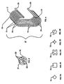
- FIGURE 3 is an enlarged schematic section view taken along section line 3-3 of Figure 2.
- FIGURE 4 shows a unit of plural hangers of the type in Figures 1-3.
- FIGURES 5A-5E are enlarged schematic section views taken along a section line, such as section 3-3 of Figure 1, provided to show representative alternative hanger sectional profiles.
- FIGURE 6 is a perspective view of a further exemplary electrically-conductive plastic hanger.
- FIGURE 7 is a perspective view of another exemplary electrically-conductive plastic hanger.
- FIGURE 8 is a perspective view of yet another exemplary electrically-conductive plastic hanger.
- FIGURE 9 is a perspective view of an additional exemplary electrically-conductive plastic hanger.
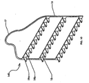
- FIGURE 10 is a perspective view of an exemplary electrically-conductive plastic hanger in the form of a rack having plural connector portions for supporting a workpiece or workpieces.
- FIGURE 11 is a perspective view of an additional exemplary electrically-conductive plastic hanger. An exemplary workpiece is supported by the hanger having second connector portion that is a plug. The exemplary electrically-conductive plastic hanger includes a first connector portion that is a breakaway hook.
- FIGURE 11A is an enlarge schematic section view taken along the
section line 11A in Figure 11. - FIGURE 12 is yet another perspective view of the exemplary electrically-conductive plastic hanger shown in Figure 11, but without the exemplary workpiece.
- FIGURE 13 is a perspective view of a further exemplary electrically-conductive plastic hanger of Figure 11, but without the exemplary workpiece.
- FIGURE 14 is yet another exemplary electrically-conductive plastic hanger. The plastic hanger includes a second connector portion that is a female plug.
- FIGURE 15 is a cross-section view taken along the
section line 14A of Figure 14. - FIGURE 16 is a perspective view of the exemplary electrically-conductive plastic hanger in Figure 14.
- FIGURE 17 is yet another exemplary electrically-conductive plastic hanger. The plastic hanger includes a first connector portion that is a breakaway eyelet.
- Referring first to Figures 1-3, those figures show a preferred embodiment of an electrically-conductive
plastic hanger 10.Hanger 10 is of the type used to support a workpiece 11 from thehook 13 of a rack, support or conveyance (not shown) during electrostatic coating, treating or processing of theworkpiece 11. Typically,hook 13 and its rack, support or conveyance are grounded or otherwise electrostatically charged.Hanger 10 serves as an electrical conductor permitting the operator to impart a desired electrostatic state or charge to workpiece 11 so that oppositely charged coatings and other materials will be attracted ontoworkpiece 11. Most typically,hanger 10 andworkpiece 11 are placed in a grounded electrostatic state. However, it is to be understood that hangers as described herein may be utilized to impart any desired charge or state to workpiece 11 so that the coating or other material is attracted toworkpiece 11. - The supported electrostatically charged
workpiece 11 may be coated, treated or processed. Typically, such treatment or processing is performed in a spray booth, submersible tank, or other apparatus adapted to apply coating or other desired material toworkpiece 11. Such operations may include any of those known to persons of skill in the art and include, without limitation, powder coating, E-coating, electro-plating, anodizing, application of autoferretic coatings as well as cleaning, etching and other forms of surface treatment. - "Plastic" as used to characterize
hanger 10 and the other hanger embodiments described herein is intended to be a broad term which means or refers to any of the numerous organic, synthetic or processed polymeric materials that can be molded, cast, extruded, drawn or otherwise made into objects such as hangers. - An "electrically-conductive plastic material" means or refers to a material which comprises a plastic component and a conductive component. The plastic component may comprise one plastic material or plural plastic materials. The conductive component may comprise one conductive material or plural conductive materials. The plastic and conductive materials may be associated by any suitable means including, for example, by embedding conductive material in the plastic. Embedding, or to embed, means or refers to making conductive material an integral part of the plastic, for example, embedding conductive particles in a plastic matrix.
- As used herein, "hanger" means or refers to any hook, support, rack, stand, framework or other contrivance from which a workpiece is hung, held or otherwise supported. A hanger may simultaneously support plural workpieces.
- "Electrostatic" means or refers to a process involving the use of electrical charge to produce attraction of the coating or other material to
workpiece 11. - Referring again to Figures 1-3,
hanger 10 shown therein has a one-piece,unitary hanger body 15 which includes first andsecond connector portions first connector portion 17 is preferably configured to hangbody 15 fromhook 13 or other support andsecond connector portion 19 is preferably configured to directly supportworkpiece 11. - In
preferred embodiment 10,body 15 is a generally C-shaped member with first andsecond connector portions body 15 preferably has a rounded shape in section. In thepreferred embodiment 10,hanger body 15, includingconnector portions -
Body 15 is made of electrically-conductive plastic material. Most preferably,body 15 is made entirely of such plastic material. Other conductive or non-conductive parts, such as a gripping appendage or an auxiliary hook (not shown), may be associated with the electrically-conductive hanger body 15. - As represented schematically in Figure 3, a preferred electrically-conductive plastic may comprise
plastic component 21 andconductive component 23 embedded therein to impart the electrical conductivity.Plastic component 21 preferably comprises a thermoplastic material. Representative thermoplastic materials include polyether ether ketones, polyphenylene sulfides, polyethylenes, liquid crystal polymers, and nylon 6-6. Any plastic material will suffice provided that the material can supporthanger 10 from a support such ashook 13 and can support aworkpiece 11. -
Conductive component 23 is selected so as to provide the desired conductivity.Conductive component 23 should be distributed throughoutplastic component 21 such thatconductive component 23 is dispersed or distributed in a generally uniform, or homogenous, manner withinbody 15. The "homogenous" dispersal or distribution ofconductive material 23 means only thatconductive material 23 is dispersed or distributed sufficiently withinbody 15 such thathanger 10 can conduct the desired electrical charge. As shown in Figure 3, in any given portion ofhanger 10,conductive material 23 can and likely will be distributed in an irregular manner withinplastic material 21. - Representative materials for use as
conductive component 23 include metallic powders, carbon black, carbon fibers, carbon mats, and metallized glass fibers and spheres. Copper, aluminum, gold, and other conductive materials may be utilized. Mixtures of the conductive materials may be utilized.Conductive material 23 may be in any form permitting generally uniform or homogenous distribution throughoutplastic material 21 comprisingbody 15. Examples are powders, flakes, granules and fibers. As shown in Figure 3,conductive material 23 can comprise conductive materials of varying sizes including, for example, large and relatively smaller materials. -
Conductive component 23 may be associated withplastic component 21 in any suitable manner. For example,conductive component 23 may be in flake or powder form and may be admixed with a granular-form plastic component 21 at any time before formation ofbody 15. Upon formation ofbody 15,conductive material 23 would be distributed or embedded withinplastic component 21. - Representative thermoplastic polyether ether ketones are sold under the trademark PEEK by Victrex USA, Inc. of Greenville, South Carolina and representative thermoplastic polyphenylene sulfides are marketed under the trade name Techtron® PPS by Boedeker Plastics, Inc. of Shiner, Texas. Each of these
representative plastic component 21 materials can be made electrically conductive by adding a 30%carbon fiber component 23 toplastic component 21. - The only requirement of the plastic and
conductive components finished hanger 10 have sufficient conductivity to adequately ground or otherwise impart an electrostatic charge to workpiece 11. Therefore,conductive component 23 must be present in sufficient amount to serve as a conductor. It is expected that the specific amount ofconductive component 23 utilized will vary based on factors such as theplastic material 21 selected and the requirements of the operator. It is possible to adjust the relative amount ofconductive material 23 inhanger body 15 to control the amount of conductivity. Preferably, the material or materials selected forcomponents hanger 10 has a very low resistance thereby facilitating charging or grounding of the workpiece supported byhanger 10. It is preferred thathanger 10 has a resistance of less than about 1 MΩ with a resistance of less than about 0.1 MΩ being more preferred. - For
hanger 10 embodiments intended for use in coating operations where high-temperature curing is required, theplastic component 21 should preferably be selected such thathanger 10 is capable of withstanding temperatures up to about 235°C. Preferably, theplastic component 21 materials can be exposed to this temperature range for about 30 minutes without deformation. Without deformation means that thehanger 10 substantially retains its configuration. Hangers such ashanger 10 are intended to be utilized in many different applications including those in which thehanger 10 andworkpiece 11 are not exposed to elevated temperatures. Hangers for use in such applications may be made of anysuitable plastic component 21 material. -
Hanger 10 is most preferably the product of conventional plastic forming processes known to persons of skill in the art.Hanger 10 may be formed, for example, by injection molding, blow molding and compression molding. The product of such a forming process is abody 15 andconnector portions - Injection molding is a particularly preferred process by which to form
hanger 10 because of the ease of preparing thecomponents conductive components components Plastic component 21 is heated until molten and then themolten plastic 21 andconductive component 23 are shot into the mold followed by cooling. - The cavity of the tool or mold may be configured to produce separate hangers (e.g., hanger 10). And, the tool or mold may be configured to simultaneously produce a group or
unit 27 of formed together hangers, one example of which is shown in Figure 4. Theunit 27 shown in Figure 4 consists of 10 hangers (each identified byreference number 10 for convenience) formed together and joined by connectors in the form ofmold runners 25.Runners 25 are not required. Any type of connector part may be used in place ofrunners 25 if connection betweenhangers 10 ofunit 27 is desired. The tool or mold may be designed such thathangers 10 can be separated or broken easily from eachrunner 25 by hand or with a cutting tool. - There is no limit with respect to the configuration and arrangement of
hangers 10 orrunners 25 or the number ofhangers 10 orrunners 25 which can be produced in a single molding operation. The objective is to provide the hanger manufacturer with flexibility to meet the operator's requirements thereby permitting the hanger manufacturer to efficientlymass produce hangers 10 and to reduce the cost of eachhanger 10. - While
preferred hanger embodiment 10 has been described in detail, it is to be understood that other hanger configurations may be utilized and that the hanger can be provided in virtually any configuration necessary to meet the needs of the operator. For example,body 15 may have sections other than the rounded section shown in Figures 1-4, and particularly in Figure 3. As shown in Figures 5A-5E, the cross-sectional configuration may be in the shape of a diamond (Figure 5A), a rectangle (Figure 5B), an I-beam (Figure 5C), a star (Figure 5D), and virtually any other shape as represented by Figure 5E. Combinations of such sectional configurations may be utilized. - By way of further example,
body 15 andconnector portions exemplary hanger 100 may have a generally C-shaped profile but with V-shapedconnector portions hanger 110 may have abody 15 withconnector portions exemplary hanger 120 may have a singlefirst connector portion 17 and pluralsecond connector portions hanger 120 to support one or more workpieces. Figure 9 shows yet another hanger embodiment 130 which utilizes a single hook asconnector portion 17 and has pluralsecond connector portions - In the embodiment of Figure 10,
hanger 140 is in the form of a rack adapted to potentially supportmany workpieces 11. Such a hanger has abody 15 which is a unitary one-piece electrically-conductive plastic part.Hanger 140body 15 includes afirst connector portion 17 comprising a bell-shaped hanger and asecond connector portion 19 comprising thirty hooks of which hooks 19a and 19b are representative.Hanger 140 could be used in place of a conventional welded-together metal rack. - And,
connector portions connector portions mechanism permitting hangers workpieces 11 to be more surely held in place. - Methods of electrostatically coating, treating or processing a workpiece using an electrically-conductive plastic hanger can be performed in manually-driven systems or in automated systems. A "system" refers to the collection of devices used in coating, treating and otherwise processing
workpiece 11. In a manually-driven system, one ormore hanger more workpiece 11. In such a manually-driven system, a human may manually connect ahanger Workpiece 11 may be connected to such hanger either before or after the hanger is connected to hook 13.Hook 13 may be in a spray booth, proximate an immersion tank or at another location such that coating material may be applied toworkpiece 11. Next, an electrostatic charge is applied to workpiece 11 throughhook 13 andhanger workpiece 11. - In an automated coating or processing system (not shown), a plurality of
hooks 13 along a conveyor each support a hanger (i.e.,hanger Hooks 13 are electrostatically charged and the charge is delivered to workpiece 11 through the hanger from which workpiece 11 is supported. The conveyor then delivers the hangers (i.e.,hanger workpieces 11 to a spray booth, immersion tank or other location for application of the coating or other material to theworkpiece 11. - After application of the coating or other material to the
workpiece 11 in either the manually or automatically driven processes, theworkpiece 11 may be cured in a curing oven or otherwise processed to yield the finished workpiece. - Electrically-
conductive hangers - Further, electrically-conductive hangers as described herein solve problems associated with such conventional supports. Electrically-
conductive hangers - As a consequence, energy-intensive cleaning methods such as burn-off cleaning and vibratory cleaning are avoided. Environmental issues are mitigated because generation of ash and off gases is avoided as is the need for chemical stripping agents.
Hangers - By providing a one-piece,
unitary hanger workpiece 11 to a metal hanger or rack is eliminated as is the need to provide a dip coating over a conventional metal hanger or hook. - Further advantages result from the optional manufacture of
hangers individual hanger 10 fromunit 27runners 25 on an as-needed basis. -
Hangers - And, because the plastic material used to make each
hanger 10 andunit 27 is lightweight as compared to metal hangers,many units 27 can be shipped easily and inexpensively to the customer. - Referring to Figures 11-17, an electrically-conductive hanger may include a masking device in the form of a closure suitable for sealing openings in a part to be electrostatically coated. As is well-known in the coatings industry, some parts have openings and internal surfaces which must be masked off and kept free from contact by solid and/or liquid coating materials. Examples are threaded weld nuts, manifolds, tubes and pipes. Typically, a plug, stopper, flanged washer or like masking device is inserted into or over such an opening before exposure of the part to the coating material. It would be desirable to combine such a masking device with an electrically-conductive hanger so that a part to be coated could be masked off and hung by the same masking device and so that an electrical charge can be conducted to the part through the hanger.
- Such a combination masking device and electrically-conductive hanger could also be used to shield a workpiece from any debris or other particulate matter it may be exposed to during shipment. For instance, in a master cylinder for a hydraulic power system, it is important to keep inner surfaces of the cylinder free of dirt and debris which might otherwise require separate cleaning processes or interfere with proper cylinder operation. In an otherwise unprotected workpiece, debris and particulate matter can collect in and around the part to be coated. In the past, it has been standard practice to insert a plug into the workpiece after coating to prevent contact with dirt and debris. This requires an additional step that imposes costs on the manufacturer. It would be desirable to provide a masking device that would serve an additional purpose of shielding a workpiece during shipment from debris.
- Examples of such electrically-
conductive hangers Hangers first portion 31 for securing the body with respect to a support and asecond portion 33 configured to at least partially mask theworkpiece 35 having a surface defining anopening 37 therein. In theembodiment 150 of Figures 11-13,second portion 33 is configured in the shape of a plug. Inalternative embodiments second portion 33 is configured in the shape of a cap, as illustrated in Figures 14-17. Of course, it is to be understood thatsecond portion 33 is not limited to being configured as a plug or a cap. Any other configuration adapted to at least partially mask workpiece opening 37 would be acceptable. - Referring now to Figures 11-17,
second portion 33 has ashank 39 and aflange 41.Shank 39 further includesthreads 43 configured for threaded engagement withcorresponding threads 45 along a surface definingworkpiece opening 37. Engagement ofshank threads 43 withcorresponding threads 45 along this surface masks workpiece opening 37, as shown in Figures 11 and 11A, thereby preventing contact with coating materials. Figure 11A is an enlarged portion of Figure 11 taken alongcircle 11A. Figure 11A illustrates the workpiece opening 37 which is masked so as to keep it free from contact by coating materials and other debris. Of course,flange 41 is not required, but rather the masking device can be configured in any manner suitable for inserting the masking device into or over an opening in a workpiece. - Referring next to Figure 15, there is shown an electrically-
conductive hanger 160 having asecond portion 33 in the form of a cap. Figure 15 is a cross-section ofhanger 160 shown in Figure 14 and taken alongsection line 14A. The cap has an internal surface configured to fit over a neck portion ofworkpiece 35, the neck portion including the surface definingworkpiece opening 37. The internal surface further includesthreads 43 configured for threaded engagement withcorresponding threads 45 along a surface definingworkpiece opening 37. Figure 15 further illustrates an embodiment whereinsecond portion 33 is a plastic threaded plug. - In certain embodiments,
first portion 31 comprises a hook, as illustrated in Figures 11-16. In the embodiment of Figure 17,hanger 170 includesfirst portion 31 that includes a member configured to define an eyelet opening. Figure 15 shows yet another embodiment utilizing a single hookfirst portion 31. It is to be understood thatfirst portion 31 is not limited to being configured in the shape of a hook or an eyelet. Any configuration offirst portion 31 that meets the an operator's requirements for securing the hanger with respect to a support is contemplated. - As shown in Figures 11-17, exemplary
first portions 31 may include abreakaway portion 47 permittingfirst portion 31 andsecond portion 33 to be easily separated from each other.Breakaway portion 47 may be a notch, narrowed area, scored portion or otherwise weakened area which permits easy disengagement offirst portion 31 fromsecond portion 33. An advantage of this arrangement is thatsecond portion 33 can be left in place in or over the surface defining workpiece opening 37 avoiding need for a separate step of inserting a plug or the like into workpiece opening 37 to prevent contact with dirt and debris. - As represented schematically in Figure 15,
hangers hangers hangers workpiece 35. It is also possible to use more flexible, lower durometric materials for friction fit of a plug in a workpiece opening. - Methods for supporting
workpiece 35 from electrically-conductiveplastic hanger embodiments second portion 33 to mask workpiece 35 having at least one surface definingworkpiece opening 37. An operator then may securefirst portion 31 with respect to a support, for example, by hangingfirst portion 31 from a support. Included in such exemplary method is the further step of imparting an electrical state to workpiece 35 through the hanger. - If
second portion 33 is provided withthreads 43, thethreads 43 are meshed withcorresponding threads 45 along the surface defining workpiece opening 37 so thatsecond portion 33 is held securely in place over the surface defining workpiece opening 37 and any other workpiece surfaces to be masked. After the surface defining workpiece opening 37 has been masked, the operator may apply a coating to the unmasked portions ofworkpiece 35. After the completion of the coating process, the method may further include separatingfirst portion 31 fromsecond portion 33 for ease of shipping. Abreakaway portion 47 onfirst portion 31, therefore, may be included to permit an operator to easily disengagefirst portion 31 fromsecond portion 33.Breakaway portion 47 may be a notch, narrowed area, scored portion or similarly weakened area. - While the principles of this invention have been described in connection with specific embodiments, it should be understood clearly that these descriptions are made only by way of example and are not intended to limit the scope of the invention.
Claims (18)
- An electrically-conductive hanger for supporting a workpiece comprising:• a one-piece hanger body, the body being of an electrically-conductive plastic material;• a first connector portion integral with the body configured to hang the body from a support; and• a second connector portion integral with the body configured to hang a workpiece from the body.
- The hanger of claim 1 wherein the electrically-conductive plastic material comprises:• at least one plastic material; and• at least one conductive material distributed homogeneously therein.
- The hanger of claims 1 or 2 wherein the plastic material is selected from one or more of the group consisting of polyether ether ketones, polyphenylene sulfides, polyethylenes, liquid crystal polymers, and nylon 6-6.
- The hanger of claims 1, 2 or 3 wherein the conductive material is selected from one or more of the group consisting of metallic powders, carbon black, carbon fibers, carbon mats, metallized glass fibers, metallized glass spheres, copper, aluminum and gold.
- The hanger of any of the preceding claims wherein the first connector portion comprises a hook and/or a member including an opening formed therein.
- The hanger of any of the preceding claims and combinations thereof wherein the first connector portion further comprises a breakaway portion and the first connector portion and second connector portions are separable at the breakaway portion.
- The hanger of claim 6 wherein the breakaway portion is a notch, narrowed area, or a scored portion.
- The hanger of any of the preceding claims and combinations thereof wherein the second connector portion is configured to at least partially mask a workpiece having at least one surface defining a workpiece opening and comprises one or more of a hook, a member including an opening formed therein, a plug, a cap or combinations thereof.
- The hanger of any of the preceding claims and combinations thereof wherein the second connector portion is configured in the shape of one or more of a hook, a cap, and a plug.
- The hanger of any of the preceding claims and combinations thereof wherein the second connector portion comprises a shank and a flange.
- The hanger of claim 10 wherein the shank further includes threads configured for threaded engagement with corresponding threads along a surface defining the workpiece opening.
- The hanger of any of the preceding claims and combinations thereof wherein the hanger body is a rack.
- The hanger of any of the preceding claims wherein the hanger body is capable of withstanding temperatures of up to about 235°C.
- The hanger of any of the preceding claims thereof wherein hangers are a plurality of hangers formed as an integral unit including a connector portion joining the hangers into the group.
- A method for supporting a workpiece from an electrically-conductive plastic hanger and for masking a workpiece having at least one surface defining a workpiece opening wherein an electrical state is imparted to the workpiece through the hanger, comprising:• providing a one-piece hanger body, the body being of an electrically conductive plastic material, wherein the body further comprises:• a first portion for securing the body with respect to a support; and• a second portion configured to at least partially mask the workpiece having at least one surface defining a workpiece opening;• masking the workpiece having at least one surface defining the workpiece opening with the second portion;• securing the first portion with respect to a support to hang the workpiece; and• imparting an electrical state to the workpiece through the hanger.
- The method of claim 15 wherein the second portion includes threads configured for threaded engagement with corresponding threads along a surface defining the workpiece opening and the method further includes engaging the second portion threads and opening threads to secure the second portion in place masking the workpiece opening.
- The method of claim 15 or 16 wherein the first portion comprises one or more of a hook and a member including an opening formed therein and the first portion further comprises a breakaway portion and the first portion and second portions are separable at the breakaway portion.
- The method of any of claims 15 to 17 further comprising applying a coating to the unmasked portions of the workpiece.
Applications Claiming Priority (2)
| Application Number | Priority Date | Filing Date | Title |
|---|---|---|---|
| US11/329,350 US20070160771A1 (en) | 2006-01-10 | 2006-01-10 | Electrically-conductive plastic hangers |
| US11/616,976 US20070158287A1 (en) | 2006-01-10 | 2006-12-28 | Electrically-Conductive Plastic Hangers |
Publications (1)
| Publication Number | Publication Date |
|---|---|
| EP1806182A1 true EP1806182A1 (en) | 2007-07-11 |
Family
ID=37963631
Family Applications (1)
| Application Number | Title | Priority Date | Filing Date |
|---|---|---|---|
| EP07000347A Withdrawn EP1806182A1 (en) | 2006-01-10 | 2007-01-09 | Electrically-conductive plastic hangers |
Country Status (3)
| Country | Link |
|---|---|
| US (1) | US20070158287A1 (en) |
| EP (1) | EP1806182A1 (en) |
| CA (1) | CA2573497A1 (en) |
Cited By (2)
| Publication number | Priority date | Publication date | Assignee | Title |
|---|---|---|---|---|
| WO2010077737A1 (en) * | 2008-12-09 | 2010-07-08 | Nordson Corporation | Low capacitance container coating system and method |
| US8828197B2 (en) * | 2007-08-06 | 2014-09-09 | Honda Motor Co., Ltd. | Holder jig for electrostatic painting |
Families Citing this family (8)
| Publication number | Priority date | Publication date | Assignee | Title |
|---|---|---|---|---|
| US20070160771A1 (en) * | 2006-01-10 | 2007-07-12 | Engineered Products And Services, Inc. | Electrically-conductive plastic hangers |
| US9144306B2 (en) | 2008-09-23 | 2015-09-29 | Jui-Chien Kao | Tool hanger |
| US20100072341A1 (en) * | 2008-09-23 | 2010-03-25 | Jui-Chien Kao | Tool hanger |
| US20110180500A1 (en) * | 2008-09-23 | 2011-07-28 | Jui-Chien Kao | Tool Hanger |
| US20130221172A1 (en) * | 2012-02-24 | 2013-08-29 | Michael Owen | Hanging apparatus and method of use |
| DE102014000918B4 (en) * | 2014-01-28 | 2024-06-27 | Rodney Kornbauer | Masking element |
| KR102408202B1 (en) * | 2021-10-26 | 2022-06-14 | 설필수 | Plating rack using conductive coating layer |
| KR102408207B1 (en) * | 2022-01-11 | 2022-06-14 | 설필수 | Tin Plating Method to Control Tin Overdissolution |
Citations (7)
| Publication number | Priority date | Publication date | Assignee | Title |
|---|---|---|---|---|
| US2730988A (en) * | 1950-06-10 | 1956-01-17 | Ransburg Electro Coating Corp | Electrostatic coating apparatus |
| US4319543A (en) * | 1980-08-25 | 1982-03-16 | Anchor Hocking Corporation | Container masking and coating apparatus |
| FR2715200A1 (en) | 1994-01-19 | 1995-07-21 | Prokap Sarl | Connector for attaching an article to be painted to a conveyor |
| US5753042A (en) * | 1996-08-08 | 1998-05-19 | Hi-Tech Flexible Products, Inc. | Flexible support for electrostatically painted parts |
| BE1011600A3 (en) * | 1997-12-10 | 1999-11-09 | Ideal Plastic Works In Het Kor | Method for treating radiators and auxiliary parts that make it possible to realise this method |
| WO2001068265A1 (en) * | 2000-03-10 | 2001-09-20 | Action Caps, Llc. | Disposable or recyclable intermediates for use in electrostatic coating plants |
| DE10236065A1 (en) * | 2002-08-07 | 2004-03-04 | Preh-Werke Gmbh & Co. Kg | Component holding device e.g. for front panel of vehicle air conditioning unit has negatives forming recesses in components fitted with variable clamping elements |
Family Cites Families (10)
| Publication number | Priority date | Publication date | Assignee | Title |
|---|---|---|---|---|
| NL193609C (en) * | 1981-12-30 | 2000-04-04 | Bekaert Sa Nv | Composite strand for processing as granulate in plastic products and method for manufacturing a plastic mixing granulate. |
| US4851081A (en) * | 1988-06-30 | 1989-07-25 | Celanese Engineering Resins | Process for preparing conductive plastic articles |
| US5477657A (en) * | 1994-03-17 | 1995-12-26 | Roberts Systems, Inc. | Method of stacking a supply of hooks on a card |
| JPH0997643A (en) * | 1995-09-29 | 1997-04-08 | Shin Etsu Polymer Co Ltd | Low resistance connector and manufacture thereof |
| WO1998042782A1 (en) * | 1997-03-24 | 1998-10-01 | Ichiro Sugimoto | Electrically conductive plastic molded article and method of production thereof |
| TW527279B (en) * | 1997-12-30 | 2003-04-11 | Dung-Han Juang | Superplastic alloy-containing conductive plastic article for shielding electromagnetic interference and process for manufacturing the same |
| US6283320B1 (en) * | 2000-12-20 | 2001-09-04 | Roger Patch | Conductive plastic container for volatile liquids |
| US6689835B2 (en) * | 2001-04-27 | 2004-02-10 | General Electric Company | Conductive plastic compositions and method of manufacture thereof |
| US6647242B2 (en) * | 2001-12-13 | 2003-11-11 | Illinois Tool Works Inc. | Flexible conductive plastic static control device |
| US6709294B1 (en) * | 2002-12-17 | 2004-03-23 | Teradyne, Inc. | Electrical connector with conductive plastic features |
-
2006
- 2006-12-28 US US11/616,976 patent/US20070158287A1/en not_active Abandoned
-
2007
- 2007-01-09 CA CA002573497A patent/CA2573497A1/en not_active Abandoned
- 2007-01-09 EP EP07000347A patent/EP1806182A1/en not_active Withdrawn
Patent Citations (8)
| Publication number | Priority date | Publication date | Assignee | Title |
|---|---|---|---|---|
| US2730988A (en) * | 1950-06-10 | 1956-01-17 | Ransburg Electro Coating Corp | Electrostatic coating apparatus |
| US4319543A (en) * | 1980-08-25 | 1982-03-16 | Anchor Hocking Corporation | Container masking and coating apparatus |
| FR2715200A1 (en) | 1994-01-19 | 1995-07-21 | Prokap Sarl | Connector for attaching an article to be painted to a conveyor |
| US5753042A (en) * | 1996-08-08 | 1998-05-19 | Hi-Tech Flexible Products, Inc. | Flexible support for electrostatically painted parts |
| BE1011600A3 (en) * | 1997-12-10 | 1999-11-09 | Ideal Plastic Works In Het Kor | Method for treating radiators and auxiliary parts that make it possible to realise this method |
| WO2001068265A1 (en) * | 2000-03-10 | 2001-09-20 | Action Caps, Llc. | Disposable or recyclable intermediates for use in electrostatic coating plants |
| US6579369B2 (en) | 2000-03-10 | 2003-06-17 | Action Caps, Llc | Protective cap for use in electrostatic coating method |
| DE10236065A1 (en) * | 2002-08-07 | 2004-03-04 | Preh-Werke Gmbh & Co. Kg | Component holding device e.g. for front panel of vehicle air conditioning unit has negatives forming recesses in components fitted with variable clamping elements |
Cited By (4)
| Publication number | Priority date | Publication date | Assignee | Title |
|---|---|---|---|---|
| US8828197B2 (en) * | 2007-08-06 | 2014-09-09 | Honda Motor Co., Ltd. | Holder jig for electrostatic painting |
| WO2010077737A1 (en) * | 2008-12-09 | 2010-07-08 | Nordson Corporation | Low capacitance container coating system and method |
| US8474402B2 (en) | 2008-12-09 | 2013-07-02 | Nordson Corporation | Low capacitance container coating system and method |
| US8852692B2 (en) | 2008-12-09 | 2014-10-07 | Nordson Corporation | Low capacitance container coating system and method |
Also Published As
| Publication number | Publication date |
|---|---|
| US20070158287A1 (en) | 2007-07-12 |
| CA2573497A1 (en) | 2007-07-10 |
Similar Documents
| Publication | Publication Date | Title |
|---|---|---|
| CA2573497A1 (en) | Electrically-conductive plastic hangers | |
| US8895112B2 (en) | Method for edge sealing a fiber-reinforced component | |
| DE60107667T2 (en) | DISPOSABLE OR RECYCLABLE INTERMEDIATE LINES FOR USE IN ELECTROSTATIC COATING SYSTEMS | |
| AU767297B2 (en) | Process for application of a fluoropolymer coating to a threaded fastener | |
| KR20090082228A (en) | Work piece carrier for carrying work piece to be painted | |
| US20070160771A1 (en) | Electrically-conductive plastic hangers | |
| EP0405025A1 (en) | Method of thread masking and thread masked part | |
| US8215502B1 (en) | Electrically conductive attachment system and rack | |
| EP2305388A1 (en) | Device for coating objects | |
| US20030113473A1 (en) | Method and apparatus for cleaning electrostatic painting hooks | |
| EP1649580A1 (en) | Method for applying an electrical insulation | |
| US20090056623A1 (en) | Coating system and method | |
| US20130286529A1 (en) | Grounding apparatus, system and method | |
| EP1455006B1 (en) | Method and apparatus for galvanizing components | |
| KR102654588B1 (en) | A Powder Coating Method for a Thick Metal Product | |
| DE3212171A1 (en) | Method and device for removing layers of surface coating agent on objects, produced by a wet coating or powder coating | |
| US8393290B2 (en) | Automated surface treatment system and method | |
| US7205027B2 (en) | Powder coating method providing enhanced finish characteristics | |
| KR101681549B1 (en) | System and method for surface treatment for rust proof | |
| KR101681557B1 (en) | Shot blast apparatus, and system and method for surface treatment system using shot blast | |
| US20050069652A1 (en) | Method for coating an object with a film and equipment therefor | |
| EP3871795B1 (en) | Method and assembly for coating motor vehicle bodies | |
| CN1162506A (en) | Bolt cover used in painting work | |
| JPH0641860U (en) | Hanger for electrodeposition coating | |
| JP3006283U (en) | Hanger for painting |
Legal Events
| Date | Code | Title | Description |
|---|---|---|---|
| PUAI | Public reference made under article 153(3) epc to a published international application that has entered the european phase |
Free format text: ORIGINAL CODE: 0009012 |
|
| AK | Designated contracting states |
Kind code of ref document: A1 Designated state(s): AT BE BG CH CY CZ DE DK EE ES FI FR GB GR HU IE IS IT LI LT LU LV MC NL PL PT RO SE SI SK TR |
|
| AX | Request for extension of the european patent |
Extension state: AL BA HR MK YU |
|
| 17P | Request for examination filed |
Effective date: 20080110 |
|
| AKX | Designation fees paid |
Designated state(s): AT BE BG CH CY CZ DE DK EE ES FI FR GB GR HU IE IS IT LI LT LU LV MC NL PL PT RO SE SI SK TR |
|
| GRAP | Despatch of communication of intention to grant a patent |
Free format text: ORIGINAL CODE: EPIDOSNIGR1 |
|
| STAA | Information on the status of an ep patent application or granted ep patent |
Free format text: STATUS: THE APPLICATION IS DEEMED TO BE WITHDRAWN |
|
| 18D | Application deemed to be withdrawn |
Effective date: 20100605 |