EP1802998B1 - Detector for nuclear medicine - Google Patents
Detector for nuclear medicine Download PDFInfo
- Publication number
- EP1802998B1 EP1802998B1 EP05786725.1A EP05786725A EP1802998B1 EP 1802998 B1 EP1802998 B1 EP 1802998B1 EP 05786725 A EP05786725 A EP 05786725A EP 1802998 B1 EP1802998 B1 EP 1802998B1
- Authority
- EP
- European Patent Office
- Prior art keywords
- detector
- slats
- radiation
- slit
- imaging device
- Prior art date
- Legal status (The legal status is an assumption and is not a legal conclusion. Google has not performed a legal analysis and makes no representation as to the accuracy of the status listed.)
- Expired - Lifetime
Links
Images


Classifications
-
- G—PHYSICS
- G01—MEASURING; TESTING
- G01T—MEASUREMENT OF NUCLEAR OR X-RADIATION
- G01T1/00—Measuring X-radiation, gamma radiation, corpuscular radiation, or cosmic radiation
- G01T1/16—Measuring radiation intensity
- G01T1/161—Applications in the field of nuclear medicine, e.g. in vivo counting
- G01T1/164—Scintigraphy
- G01T1/1641—Static instruments for imaging the distribution of radioactivity in one or two dimensions using one or several scintillating elements; Radio-isotope cameras
- G01T1/1648—Ancillary equipment for scintillation cameras, e.g. reference markers, devices for removing motion artifacts, calibration devices
-
- A—HUMAN NECESSITIES
- A61—MEDICAL OR VETERINARY SCIENCE; HYGIENE
- A61B—DIAGNOSIS; SURGERY; IDENTIFICATION
- A61B6/00—Apparatus or devices for radiation diagnosis; Apparatus or devices for radiation diagnosis combined with radiation therapy equipment
- A61B6/42—Arrangements for detecting radiation specially adapted for radiation diagnosis
- A61B6/4291—Arrangements for detecting radiation specially adapted for radiation diagnosis the detector being combined with a grid or grating
-
- G—PHYSICS
- G01—MEASURING; TESTING
- G01T—MEASUREMENT OF NUCLEAR OR X-RADIATION
- G01T1/00—Measuring X-radiation, gamma radiation, corpuscular radiation, or cosmic radiation
- G01T1/16—Measuring radiation intensity
- G01T1/161—Applications in the field of nuclear medicine, e.g. in vivo counting
- G01T1/1615—Applications in the field of nuclear medicine, e.g. in vivo counting using both transmission and emission sources simultaneously
-
- G—PHYSICS
- G01—MEASURING; TESTING
- G01T—MEASUREMENT OF NUCLEAR OR X-RADIATION
- G01T1/00—Measuring X-radiation, gamma radiation, corpuscular radiation, or cosmic radiation
- G01T1/16—Measuring radiation intensity
- G01T1/161—Applications in the field of nuclear medicine, e.g. in vivo counting
- G01T1/164—Scintigraphy
- G01T1/1641—Static instruments for imaging the distribution of radioactivity in one or two dimensions using one or several scintillating elements; Radio-isotope cameras
- G01T1/1644—Static instruments for imaging the distribution of radioactivity in one or two dimensions using one or several scintillating elements; Radio-isotope cameras using an array of optically separate scintillation elements permitting direct location of scintillations
-
- G—PHYSICS
- G21—NUCLEAR PHYSICS; NUCLEAR ENGINEERING
- G21K—HANDLING OF PARTICLES OR IONISING RADIATION NOT OTHERWISE PROVIDED FOR; IRRADIATION DEVICES; GAMMA RAY OR X-RAY MICROSCOPES
- G21K1/00—Arrangements for handling particles or ionising radiation, e.g. focusing or moderating
- G21K1/02—Arrangements for handling particles or ionising radiation, e.g. focusing or moderating using diaphragms, collimators
- G21K1/025—Arrangements for handling particles or ionising radiation, e.g. focusing or moderating using diaphragms, collimators using multiple collimators, e.g. Bucky screens; other devices for eliminating undesired or dispersed radiation
-
- A—HUMAN NECESSITIES
- A61—MEDICAL OR VETERINARY SCIENCE; HYGIENE
- A61B—DIAGNOSIS; SURGERY; IDENTIFICATION
- A61B6/00—Apparatus or devices for radiation diagnosis; Apparatus or devices for radiation diagnosis combined with radiation therapy equipment
- A61B6/02—Arrangements for diagnosis sequentially in different planes; Stereoscopic radiation diagnosis
- A61B6/03—Computed tomography [CT]
- A61B6/037—Emission tomography
Definitions
- the present application relates to the production of images with a nuclear camera. It finds particular application in conjunction with a fan beam collimator having a slit, and will be described with particular reference thereto. However, it is to be appreciated that the present exemplary embodiment is also amenable to other like applications.
- Nuclear imaging techniques generally obtain images in one of two different ways.
- Emission images are generated by introducing a radioactive isotope to the subject and collecting radiation coming from within the subject with a detector sensitive to such radiation (camera).
- Such emission images include Single Photon Emission Computed Tomography (SPECT) images and are often used to provide functional information regarding the subject, such as a tumor within a patient.
- SPECT Single Photon Emission Computed Tomography
- Transmission images are generated by positioning the subject intermediate a radiation source, such as a source of gamma radiation, and the detector so that the radiation that passes through the subject is detected with the camera. Transmission images provide information about the distribution of radiation-attenuating or radiation-absorbing matter in the subject.
- a radiation source such as a source of gamma radiation
- Transmission images and emission images are often performed simultaneously, for example, for correction of the emission image for attenuation of the radiation in the object.
- a SPECT imaging device is sometimes used to generate both emission and transmission images.
- Photons generated inside and transmitted through the subject are detected by the detector, such as an NaI crystal and an array of photomultipliers.
- a collimator is placed before the camera.
- a predetermined spatial geometry of the radiation source also determines the trajectory of the transmission radiation events.
- the collimator which includes a grid or honeycomb-like array of radiation absorbent material, is located between the detector and the subject being examined to limit the angle of acceptance of radiation which impinges on the detector. Resolution and efficiency are defined by the shape of the collimator and the height and thickness of septa defining grid, with thicker septa generally being used for higher energy ranges.
- Static detectors i.e., those which maintain the same general orientation towards the radiation source
- the parallel hole detector includes a collimator with parallel slats in a first direction which intersect parallel slats in a second direction.
- the collimator is used in combination with a planar source for transmission measurements.
- planar radiation source radiates radiation in all directions within a particular solid angle, but only a very limited portion is utilized in making the transmission image, namely, only the portion that is directed in the direction of the passages of the collimator.
- a relatively strong source is used for making a transmission image with a predetermined brightness.
- Improvements in efficiency over the parallel hole detector may be achieved by focused collimators in which the slats are oriented towards a focus which is at the same side of the collimator as the object to be measured.
- a fan beam collimator includes slats which are focused in one direction and which are parallel in the other direction. The fan beam collimator is used with a line radiation source for transmission measurements which is arranged along the focal line.
- a cone beam collimator includes slats which are focused in both directions and may be used with a point radiation source at the focal point for transmission measurement.
- dynamic detector concepts have been proposed, among them rotating slat or slit detectors, coded aperture imaging, and overlapping detector regions. These concepts tend to suffer from noise accumulation due to the necessary extra reconstruction step.
- US 4,066,901 A discloses an axial tomography system which includes an assembly rotatable about an axis extending along a central opening defined therein, and means for positioning the body portion to be examined within the central opening so that the axis of assembly rotation is perpendicular to a plane passing through the bodily structures to be examined.
- a source of penetrating radiation is mounted on the assembly toward one side thereof and via a first collimating means provides radiation in the form of a fan beam.
- the first collimating means is mounted proximate to the radiation source, and includes an adjustable slit, which can be opened completely to enable a conventional x-ray exposure.
- Means are provided for rotating the assembly so that the fan beam impinges upon said body portion at a plurality of incident directions.
- Detector means for the radiation are positioned on the assembly opposite the source, enabling detection of radiation which traverses laterally and is not absorbed in the thin body section in which the aforementioned plane resides.
- the detector means is preferably of the ionization type, and may comprise an array of side-by-side cells.
- Second collimating means including a series of parallel plates overlie the detector means and assure that the radiation incident on each cell is substantially only that which has propagated along the radius of the fan beam which joins the cell to the radiation source.
- a third collimating means directly overlies the second, and comprises a slit extending transversely to the aforementioned plates.
- US 4,277,684 A discloses an X-ray collimator for use in computerized axial tomography apparatus including a plurality of substantially parallel X-ray absorbing laminae disposed in the plane of a wedge-shaped X-ray beam.
- the length and position of each lamina with respect to a divergent X-ray source is chosen to maximize the ratio of X-ray flux impinging upon a detector array to flux falling within the collimator's penumbra, outside the detector array.
- a single set of moveable jaws may be disposed at the collimator exit for adjustment of the beam thickness.
- a nuclear imaging device including at least one radiation imaging device is provided as defined in claim 1.
- the imaging device includes a detector.
- a collimator is positioned adjacent a radiation receiving face of the detector.
- the collimator includes a plurality of slats having a common focus.
- a body, adjacent the slats, defines an elongate slit.
- the slit is arranged such that radiation passes through the slit and between the slats to the detector.
- the body is at least substantially impermeable to the radiation.
- a nuclear imaging method is provided as defined in claim 13.
- the method includes directing radiation from a source towards a detector and interposing a slit and a plurality of spaced slats having a common focus between the radiation source and the detector, whereby radiation passes through the slit and between the slats onto the detector.
- An advantage of at least one embodiment arises from the ability to achieve higher efficiencies than for other static detector concepts.
- the invention may take form in various components and arrangements of components, and in various steps and arrangements of steps.
- the drawings are only for purposes of illustrating the preferred embodiments and are not to be construed as limiting the invention.
- the imaging system includes an imaging region 10 in which a subject, such as a patient 12 lies or is transported therethrough on a moveable support 14.
- a subject such as a patient 12 lies or is transported therethrough on a moveable support 14.
- One or more radiation detection systems or heads 16 are positioned adjacent to the patient to monitor and record transmitted and/or emitted radiation events.
- a source of transmission radiation 18, such as a gamma radiation source, is positioned such that radiation emitted by the source enters the subject and received in the form of photons by an opposing detection system 16.
- a radiopharmaceutical introduced to the subject 12 serves as a source of radiation for SPECT imaging.
- the emission and transmission radiation have different energies to facilitate differentiating them.
- the detection system includes a collimator 20 and a detector 22.
- the collimator is positioned intermediate the subject 12 and the detector 22 to limit the angle of acceptance of radiation which impinges on the detector.
- the detector 22 is linked to a processing system 24, which may be embodied in an operator work station, computer network, or other suitable hardware/software.
- the processing system 24 reconstructs an image of the subject, based on signals from the detector, which is displayed by a display 26, such as a screen or printout.
- the detector 22 includes a sensor, which detects radiation (typically photons) generated as a result of the interaction of the radiation with the subject.
- a sensor which detects radiation (typically photons) generated as a result of the interaction of the radiation with the subject.
- One suitable sensor includes a scintillator, such as a single crystal, such as a sodium iodide crystal, or a matrix of smaller crystals. The crystal is positioned adjacent a matrix of photomultiplier tubes ("PMTs"). Each radiation event impinging on the scintillator generates a corresponding flash of light (scintillation) that is seen by the PMTs. Based on the outputs from the PMTs, radiation events are mapped, which include the energy and position of radiation rays impinging the scintillator.
- PMTs photomultiplier tubes
- detectors include a matrix of scintillation crystals, i.e. a pixelated detector, which are mated with photodiodes or avalanche detectors in place of photomultiplier tubes.
- a cadmium zinc telluride (CZT) or other direct conversion detector is used which converts radiation photons directly to electrons (current) without a scintillator.
- the image quality of the SPECT images is typically determined by a count sensitivity of the detector and the geometry of the collimator.
- the collimator 20 is formed of a dense radiation absorbing material, such as tungsten.
- the collimator 20 can be regarded as a transmission means with a direction-selective transmission characteristic, which ensures that a detection segment of the detection surface of the detector can only be irradiated by radiation with a predetermined limited range of directions.
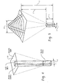
- the presently illustrated collimator can be described as a fan beam-slit collimator.
- the fan beam portion of the collimator is provided by a plurality of closely spaced slats or septa 30 (five are illustrated but the number is typically much larger).
- the slats 30 are planar.
- a generally planar radiation receiving face or detection surface 32 of the detector 22 lies in a plane defined by y and x axes and the collimator slats 30 extend away from the plane generally in a z direction.
- the slats 30 extend from the planar surface 32 of the detector towards the radiation source 18 and converge towards a focal line 34.
- the source 18 comprises a line source which is collinear with the focal line 34 of the slats for optimal efficiency, although it is also contemplated that the source may be spaced further from, or closer to the detector 22.
- the outer slats are oriented at a shallower angle ⁇ to the plane of the detector than the inner slats, the angle ⁇ increasing towards the center, where the center slat is oriented at, 90° to the plane x, y.
- the slats 30 define a plurality of parallel passages 36 therebetween. As a result of the focused slats, a centerline of each passage intersects the line-shaped radiation source 18.
- the passages 36 extend the full width B of the detector plane in the x direction, i.e., there are no intersecting slats as in a conventional fan beam or cone-shaped collimator.
- Ends 40 of the slats closest to the detector 22 are equally spaced, adjacent the detector in the y direction, with a pitch P y .
- the slats have a height L in the z direction and a width B in the x direction, which is greater than the height L.
- the pitch P y is about 1-3 mm
- the distance between adjacent slats D is about 0.80 to about 2.95 mm
- the thickness of the slats t is about 0.05 mm to about 0.5 mm, e.g., about 0.15 mm
- the height L is from about 10 mm to about 100mm, and in one specific embodiment, L is less than about 60 mm.
- the slit portion of the collimator is defined by a body generally in the form of a plate 44 which lies in a plane parallel to the plane 36 of the detector 22.
- the plate is formed of a radiation opaque material, such as a radiation impermeable, or substantially impermeable material.
- the plate defines an elongate slit 46 which extends a length G of the detector in the y direction, which is greater than the distance P y between slats.
- the slit has a width w in the x direction. Length G is substantially greater than the width w. In one embodiment, w is from about 0.3 mm to about 3 mm, the narrower the slit, the higher the resolution.
- the plate 44 has a thickness h in the z direction, which is the height of the slit 46, of from about 0.5mm to about 5mm, the higher thickness being more suited to higher energies.
- the plate 44 is located at height L above the plane 32, i.e., in contact with upper ends 48 of the slats 30 although it is also contemplated that the plate may be spaced from the plane by a distance somewhat greater than L , but generally less than 2 L .
- the focus 34 is located a distance ⁇ from the plane 44.
- Side walls 50 of the slit may be aligned with the z axis, as shown, or angled to the z axis, for example in a V shape or an inverted V shape.
- the illustrated detector 22 is pixellated. As shown in FIGURE 2 , a row of pixels 52 extends between each pair of adjacent slats 30. The pixels are configured for independently sending signals to the processing system 24.
- the pixels each have a pixel width or pitch P x in the x direction and a length D in the y direction. In one embodiment, P x is from about 0.5 mm to about 2.5 mm. Seven pixels 52 are illustrated in each row/passage, although a much greater number of pixels is typically employed.
- the pixel pitch P x is greater than or equal to half the slit width w but less than the interval between slits.
- the field of view (FOV) 62 is the area within the plane.
- the area of the projected image on the detector, which in the embodiment of FIGURE 2 is defined by the area of the plane 32, is smaller in the x direction than the object plane.
- each pixel 52 in the detector has an area P x x D, which is smaller in the x direction and larger in the y direction than the area of a corresponding pixel 64 in the object plane, resulting in a magnifying effect in the y direction.
- the detector plane 32 is typically larger than the projected image, for example, where multiple slits and/or multiple modules are employed.
- each slit serves a different portion, or partially overlapping portion of the detector plane 32, to increase the area of detection.
- the slits are oriented parallel to one another, as illustrated in FIGURES 6 and 7 , each slit and its associated slats comprising a module.
- the slats of one module may be continuations of the slats of an adjacent module. Or, more than one module may share the same slit.
- the spacing S between adjacent slits is from about 5 to 100 mm, and in one specific embodiment, from 5 to 50 mm ( FIGURE 7 ).
- the detector 22 is a static detector, i.e., does not rotate but remains fixed, relative to the slats and detector plane.
- the entire detector system 16 may, of course, rotate around the subject, for example, by means of a rotating gantry.
- the fan beam-slit collimator finds particular application in planar or SPECT imaging. Planar imaging is performed without rotation of the detector about the patient.
- the detector is also suitable for use in a rolec-type camera in which the detector rotates about an axis that is perpendicular to the detector plane.
- the fan beam-slit arrangement is beneficial for optimizing efficiency while maintaining resolution.
- simultaneous optimization of slat length (for the fan beam) and collimator-detector distance (for the slit) in combination with parallel readout of neighboring detector areas which is possible when slit collimators are used with solid state detectors in de-magnification mode, provides a performance which exceeds that of conventional detection systems.
- thick slats are used for high energy photons, the optimization is not completely possible, but efficiency values are still high.
- An analytical model for spatial resolution and geometric efficiency of a collimator in combination with a pixellated detector such as a pixellated CZT- based detector, can be derived.
- Descriptions for static and rotating detector concepts can be derived, for example, using National Electrical Manufacturers Association (NEMA) performance criteria for detection efficiency and measures adapted for spatial resolution of pixellated detectors, based on the sampling of the single pixel response function.
- NEMA National Electrical Manufacturers Association
- Geometric efficiency E is calculated as part of the radiation from a point source that irradiates the open detector area of one pixel (normalized solid angle), multiplied by the average area in the object plane that is seen by any point on the detector pixel (region seen) and normalized by the area of the object plane equivalent to one pixel (voxel area) as shown schematically in FIGURE 4 .
- Resolution R ( FIGURE 5 ) is calculated as the full-width at half-maximum (FWHM) of the single pixel detector response for a point source in the object plane, integrated in one dimension.
- FWHM full-width at half-maximum
- Focused collimators provide higher efficiency at the expense of a smaller field-of-view (FOV) or, equivalently, larger detector area.
- the solid angle is reduced by a factor cos 3 ⁇ for all pixels outside the center part of the detector, explained by the oblique angle of incidence ⁇ and the larger object-detector distance.
- the region seen is reduced by a factor ⁇ / ⁇ ' or ( ⁇ / ⁇ ' ) 2 , and the voxel area is given by the pixel area divided by m for a fan beam (for a cone beam the voxel area is given by the pixel area divided by p 2 / m 2 ).
- the linear magnification factor m is defined by the slit geometry in the x direction and the pixel pitch P y defined by the slats in the y direction.
- slat distance: D y RL ⁇ ' / z' ⁇
- Dy > D x .
- Pixel: in x: p x D x ⁇ z ⁇ 2 ⁇ z
- in y: p y D y + t, P y > P x .
- Table 1 shows performance parameters of pixellated detector concepts, six of conventional type and two with fan beam-slit collimators of the type disclosed herein.
- collimator geometry is defined by pixel size D , septa length or collimator-detector distance L.
- Performance is given in terms of spatial resolution R, efficiency E, space-bandwidth product, SBP, which is essentially the number of detector pixels when the Nyquist criterion is fulfilled.
- Another method of expressing efficiency is as the efficiency-space-bandwidth product, ESBP, a measure of the amount of information received by different collimators. All detector values are calculated for 0.152 mm septa thickness (VXGP) and 5 mm resolution at 100 mm source-collimator distance.
- Two configurations of a fan beam-slit collimator are considered. Both employ more than one module, i.e., a plurality of slits. In both cases, five slits were used. The focus of the slats, ⁇ (and the location of the source) was 10-20 cm.
- the field of view 62 (FOV) is 55 cm in the x direction and 40 cm in the y direction.
- the slits 46 are oriented in the y direction, the slats (not shown) are oriented in the x direction.
- Several modules sharing a long slit overlap the 40 cm FOV 62 in the y direction. A large number of modules cover the 55 cm FOV in the x direction. Due to the large opening angle of the fan beams in the y direction, the average efficiency is reduced (the correction factor a cone given above is much smaller than 1).
- FIGURE 7 In the second configuration ( FIGURE 7 ) two detector module arrangements (called 'rings' if they form part of a ring around the object) with 55 cm in the x direction and a much smaller size in y are shown. A third detector module arrangement is shown under a different SPECT angle. Modules are smaller in the y direction, therefore the opening angle is smaller and the efficiency is higher (the correction factor a cone given above is nearly equal to 1). Each of the module 'rings' sees only the corresponding region 62A, 62B. The missing region 70 in between the rectangles 62A, 62B is imaged by a shift of the detector rings in y or by additional detectors 74 under different SPECT angles, as shown in FIGURE 7 .
- the first value of D for the Fan Beam Slit configurations 1 and 2 corresponds to the distance between the slats in the y direction and the second value of D corresponds to the slit width w.
- the ESBP of a fan-beam slit collimator is more than 50% higher than the value for a parallel hole collimator when the concept is applied on a large camera (Configuration 1), and it is more than 250% of the parallel hole collimator value when the concept is applied on small modules or rings (Configuration 2), which is a two times higher efficiency than for other detector concepts, such as multi-pinhole.
- This high value is achieved by a five-fold number of readout channels and an 83% larger detector area compared to a parallel hole detector.
- High efficiency can thus be achieved with only moderate increase in detector area and number of readout channels (compared to a multi-pinhole detector concept).
Landscapes
- Physics & Mathematics (AREA)
- Health & Medical Sciences (AREA)
- Engineering & Computer Science (AREA)
- Life Sciences & Earth Sciences (AREA)
- High Energy & Nuclear Physics (AREA)
- Spectroscopy & Molecular Physics (AREA)
- Medical Informatics (AREA)
- Nuclear Medicine, Radiotherapy & Molecular Imaging (AREA)
- Optics & Photonics (AREA)
- General Health & Medical Sciences (AREA)
- Molecular Biology (AREA)
- Biomedical Technology (AREA)
- General Physics & Mathematics (AREA)
- General Engineering & Computer Science (AREA)
- Radiology & Medical Imaging (AREA)
- Pathology (AREA)
- Biophysics (AREA)
- Heart & Thoracic Surgery (AREA)
- Surgery (AREA)
- Animal Behavior & Ethology (AREA)
- Public Health (AREA)
- Veterinary Medicine (AREA)
- Measurement Of Radiation (AREA)
- Nuclear Medicine (AREA)
Applications Claiming Priority (3)
| Application Number | Priority Date | Filing Date | Title |
|---|---|---|---|
| US61908004P | 2004-10-15 | 2004-10-15 | |
| US63674504P | 2004-12-16 | 2004-12-16 | |
| PCT/IB2005/053231 WO2006040707A1 (en) | 2004-10-15 | 2005-09-30 | Detector for nuclear medicine |
Publications (2)
| Publication Number | Publication Date |
|---|---|
| EP1802998A1 EP1802998A1 (en) | 2007-07-04 |
| EP1802998B1 true EP1802998B1 (en) | 2014-09-17 |
Family
ID=35355907
Family Applications (1)
| Application Number | Title | Priority Date | Filing Date |
|---|---|---|---|
| EP05786725.1A Expired - Lifetime EP1802998B1 (en) | 2004-10-15 | 2005-09-30 | Detector for nuclear medicine |
Country Status (5)
| Country | Link |
|---|---|
| US (1) | US7683333B2 (https=) |
| EP (1) | EP1802998B1 (https=) |
| JP (1) | JP5283382B2 (https=) |
| CN (1) | CN101040193B (https=) |
| WO (1) | WO2006040707A1 (https=) |
Families Citing this family (13)
| Publication number | Priority date | Publication date | Assignee | Title |
|---|---|---|---|---|
| US8242453B2 (en) | 2004-10-15 | 2012-08-14 | Koninklijke Philips Electronics N.V. | Imaging system for nuclear medicine |
| US8552389B2 (en) | 2010-10-29 | 2013-10-08 | General Electric Company | System and method for collimation in diagnostic imaging systems |
| DE102010062133B4 (de) * | 2010-11-29 | 2017-02-23 | Siemens Healthcare Gmbh | Kollimator für einen Strahlendetektor und Verfahren zur Herstellung eines solchen Kollimators sowie Verfahren zur Herstellung eines Kollimatoren aufweisenden Strahlendetektors |
| RU2014125267A (ru) * | 2011-11-22 | 2015-12-27 | Конинклейке Филипс Н.В. | Система офэкт всего тела |
| US20130345550A1 (en) * | 2012-06-25 | 2013-12-26 | Tzachi Rafaeli | Systems and methods for localizing an opaque medical device with nuclear medicine imaging |
| NL2012546B1 (nl) | 2014-04-02 | 2016-02-15 | Milabs Bv | Scannen van een menselijk lichaamsdeel met door het lichaamsdeel uitgezonden hoogenergetische straling. |
| US11350892B2 (en) * | 2016-12-16 | 2022-06-07 | General Electric Company | Collimator structure for an imaging system |
| JP6822859B2 (ja) * | 2017-01-24 | 2021-01-27 | キヤノンメディカルシステムズ株式会社 | 検出装置及び検出方法 |
| US11723609B2 (en) | 2020-08-28 | 2023-08-15 | Argospect Technologies Inc. | Spread field imaging collimators for radiation-based imaging and methods of using the same |
| EP4330730B1 (en) * | 2022-07-15 | 2025-09-17 | Shanghai United Imaging Healthcare Co., Ltd. | Detector module |
| NL2036201B1 (en) * | 2023-11-07 | 2025-05-19 | Stichting The Molecular Imaging | A gamma radiation imaging system, collimator assembly, and method |
| WO2025098964A1 (en) * | 2023-11-07 | 2025-05-15 | Stichting The Molecular Imaging | A gamma radiation imaging system, collimator assembly, and method |
| US20260120909A1 (en) * | 2024-10-31 | 2026-04-30 | GE Precision Healthcare LLC | Imaging system collimator for high energy and low energy isotopes |
Family Cites Families (13)
| Publication number | Priority date | Publication date | Assignee | Title |
|---|---|---|---|---|
| US4066901A (en) * | 1976-09-13 | 1978-01-03 | Varian Associates, Inc. | Tomographic scanning apparatus with improved collimator structure |
| US4277684A (en) * | 1977-08-18 | 1981-07-07 | U.S. Philips Corporation | X-Ray collimator, particularly for use in computerized axial tomography apparatus |
| JPS6085383A (ja) * | 1983-10-15 | 1985-05-14 | Mitsubishi Electric Corp | 放射線イメ−ジング装置 |
| NL8701122A (nl) * | 1987-05-12 | 1988-12-01 | Optische Ind De Oude Delft Nv | Inrichting voor spleetradiografie met beeldharmonisatie. |
| JP2957623B2 (ja) | 1990-01-31 | 1999-10-06 | 株式会社東芝 | Spect装置用のアーチファクト乃至感度補正装置 |
| JPH04297899A (ja) | 1991-03-27 | 1992-10-21 | Toshiba Corp | コリメータ製造方法及び該製造方法で得るコリメータ |
| US5210421A (en) * | 1991-06-10 | 1993-05-11 | Picker International, Inc. | Simultaneous transmission and emission converging tomography |
| NL1003081C2 (nl) * | 1996-05-10 | 1997-11-18 | Frederik Johannes Beekman | Convergerende collimatoren gecombineerd met bewegende energievensters en virtueel kleine puntbronnen voor het maken van betere transmissieopnamen van objecten die gammastraling uitzenden. |
| EP1120086A4 (en) * | 1998-09-17 | 2003-05-21 | Quanta Vision Inc | DEVICE FOR REDUCED ANGLE MAMMOGRAPHY AND VARIANTS |
| JP2003520348A (ja) | 2000-01-14 | 2003-07-02 | バン・ドウルメン,アドリアヌス・エイ | 単光子放出型コンピュータ撮影法による撮像方法 |
| US6583420B1 (en) * | 2000-06-07 | 2003-06-24 | Robert S. Nelson | Device and system for improved imaging in nuclear medicine and mammography |
| US6603123B1 (en) * | 2000-11-08 | 2003-08-05 | Koninklijke Philips Electronics, N.V. | Correction for depth-dependent sensitivity in rotating slat-collimated gamma camera |
| US20040044282A1 (en) * | 2002-08-28 | 2004-03-04 | Mixon Lonnie Mark | Medical imaging systems and methods |
-
2005
- 2005-09-30 US US11/577,093 patent/US7683333B2/en active Active
- 2005-09-30 WO PCT/IB2005/053231 patent/WO2006040707A1/en not_active Ceased
- 2005-09-30 EP EP05786725.1A patent/EP1802998B1/en not_active Expired - Lifetime
- 2005-09-30 JP JP2007536301A patent/JP5283382B2/ja not_active Expired - Lifetime
- 2005-09-30 CN CN200580035245.7A patent/CN101040193B/zh not_active Expired - Lifetime
Also Published As
| Publication number | Publication date |
|---|---|
| WO2006040707A1 (en) | 2006-04-20 |
| EP1802998A1 (en) | 2007-07-04 |
| JP5283382B2 (ja) | 2013-09-04 |
| CN101040193B (zh) | 2010-06-16 |
| JP2008524554A (ja) | 2008-07-10 |
| US20090022279A1 (en) | 2009-01-22 |
| US7683333B2 (en) | 2010-03-23 |
| CN101040193A (zh) | 2007-09-19 |
Similar Documents
| Publication | Publication Date | Title |
|---|---|---|
| US6377661B1 (en) | Radiation imager collimator | |
| US6943355B2 (en) | SPECT gamma camera | |
| US7916831B2 (en) | X-ray detector and X-ray CT apparatus | |
| US7696481B2 (en) | Multi-layered detector system for high resolution computed tomography | |
| US9076563B2 (en) | Anti-scatter collimators for detector systems of multi-slice X-ray computed tomography systems | |
| US20120039446A1 (en) | Interwoven multi-aperture collimator for 3-dimensional radiation imaging applications | |
| EP1802998B1 (en) | Detector for nuclear medicine | |
| US20030111609A1 (en) | Correction for depth-dependent sensitivity in rotating slat-collimated gamma camera | |
| US8242453B2 (en) | Imaging system for nuclear medicine | |
| US20180329078A1 (en) | Systems and methods for improved collimation sensitivity | |
| US9349495B2 (en) | Systems and methods for improved collimation sensitivity | |
| US7989771B2 (en) | Pinhole SPECT camera with plural detector heads | |
| US10324200B2 (en) | Systems and methods for improved collimation sensitivity | |
| US20140314196A1 (en) | Tilted detector array for medical imaging systems including computed tomography | |
| US9230702B2 (en) | System and method for reducing grid line image artifacts | |
| JP5242080B2 (ja) | X線検出器およびx線ct装置 | |
| JP2004337609A (ja) | コンピュータ断層撮影システム用コリメータ組立体 | |
| US7551712B2 (en) | CT detector with non-rectangular cells | |
| JP7118133B2 (ja) | 光子カウントコンピュータ断層撮影のための薄型散乱防止及び電荷共有防止グリッド、当該グリッドを有する撮像装置、当該グリッドの製造方法 | |
| JPH08233941A (ja) | ポジトロンct装置 |
Legal Events
| Date | Code | Title | Description |
|---|---|---|---|
| PUAI | Public reference made under article 153(3) epc to a published international application that has entered the european phase |
Free format text: ORIGINAL CODE: 0009012 |
|
| 17P | Request for examination filed |
Effective date: 20070515 |
|
| AK | Designated contracting states |
Kind code of ref document: A1 Designated state(s): AT BE BG CH CY CZ DE DK EE ES FI FR GB GR HU IE IS IT LI LT LU LV MC NL PL PT RO SE SI SK TR |
|
| DAX | Request for extension of the european patent (deleted) | ||
| 17Q | First examination report despatched |
Effective date: 20121005 |
|
| RAP1 | Party data changed (applicant data changed or rights of an application transferred) |
Owner name: KONINKLIJKE PHILIPS N.V. |
|
| GRAP | Despatch of communication of intention to grant a patent |
Free format text: ORIGINAL CODE: EPIDOSNIGR1 |
|
| RIC1 | Information provided on ipc code assigned before grant |
Ipc: G21K 1/02 20060101ALI20140313BHEP Ipc: G01T 1/164 20060101AFI20140313BHEP Ipc: G01T 1/161 20060101ALI20140313BHEP |
|
| INTG | Intention to grant announced |
Effective date: 20140417 |
|
| GRAS | Grant fee paid |
Free format text: ORIGINAL CODE: EPIDOSNIGR3 |
|
| GRAA | (expected) grant |
Free format text: ORIGINAL CODE: 0009210 |
|
| AK | Designated contracting states |
Kind code of ref document: B1 Designated state(s): AT BE BG CH CY CZ DE DK EE ES FI FR GB GR HU IE IS IT LI LT LU LV MC NL PL PT RO SE SI SK TR |
|
| REG | Reference to a national code |
Ref country code: GB Ref legal event code: FG4D |
|
| REG | Reference to a national code |
Ref country code: CH Ref legal event code: EP |
|
| REG | Reference to a national code |
Ref country code: IE Ref legal event code: FG4D |
|
| REG | Reference to a national code |
Ref country code: AT Ref legal event code: REF Ref document number: 687936 Country of ref document: AT Kind code of ref document: T Effective date: 20141015 |
|
| REG | Reference to a national code |
Ref country code: DE Ref legal event code: R096 Ref document number: 602005044748 Country of ref document: DE Effective date: 20141030 |
|
| PG25 | Lapsed in a contracting state [announced via postgrant information from national office to epo] |
Ref country code: LT Free format text: LAPSE BECAUSE OF FAILURE TO SUBMIT A TRANSLATION OF THE DESCRIPTION OR TO PAY THE FEE WITHIN THE PRESCRIBED TIME-LIMIT Effective date: 20140917 Ref country code: SE Free format text: LAPSE BECAUSE OF FAILURE TO SUBMIT A TRANSLATION OF THE DESCRIPTION OR TO PAY THE FEE WITHIN THE PRESCRIBED TIME-LIMIT Effective date: 20140917 Ref country code: GR Free format text: LAPSE BECAUSE OF FAILURE TO SUBMIT A TRANSLATION OF THE DESCRIPTION OR TO PAY THE FEE WITHIN THE PRESCRIBED TIME-LIMIT Effective date: 20141218 Ref country code: FI Free format text: LAPSE BECAUSE OF FAILURE TO SUBMIT A TRANSLATION OF THE DESCRIPTION OR TO PAY THE FEE WITHIN THE PRESCRIBED TIME-LIMIT Effective date: 20140917 |
|
| REG | Reference to a national code |
Ref country code: NL Ref legal event code: VDEP Effective date: 20140917 |
|
| REG | Reference to a national code |
Ref country code: LT Ref legal event code: MG4D |
|
| PG25 | Lapsed in a contracting state [announced via postgrant information from national office to epo] |
Ref country code: LV Free format text: LAPSE BECAUSE OF FAILURE TO SUBMIT A TRANSLATION OF THE DESCRIPTION OR TO PAY THE FEE WITHIN THE PRESCRIBED TIME-LIMIT Effective date: 20140917 Ref country code: CY Free format text: LAPSE BECAUSE OF FAILURE TO SUBMIT A TRANSLATION OF THE DESCRIPTION OR TO PAY THE FEE WITHIN THE PRESCRIBED TIME-LIMIT Effective date: 20140917 |
|
| REG | Reference to a national code |
Ref country code: AT Ref legal event code: MK05 Ref document number: 687936 Country of ref document: AT Kind code of ref document: T Effective date: 20140917 |
|
| PG25 | Lapsed in a contracting state [announced via postgrant information from national office to epo] |
Ref country code: NL Free format text: LAPSE BECAUSE OF FAILURE TO SUBMIT A TRANSLATION OF THE DESCRIPTION OR TO PAY THE FEE WITHIN THE PRESCRIBED TIME-LIMIT Effective date: 20140917 |
|
| PG25 | Lapsed in a contracting state [announced via postgrant information from national office to epo] |
Ref country code: PT Free format text: LAPSE BECAUSE OF FAILURE TO SUBMIT A TRANSLATION OF THE DESCRIPTION OR TO PAY THE FEE WITHIN THE PRESCRIBED TIME-LIMIT Effective date: 20150119 Ref country code: EE Free format text: LAPSE BECAUSE OF FAILURE TO SUBMIT A TRANSLATION OF THE DESCRIPTION OR TO PAY THE FEE WITHIN THE PRESCRIBED TIME-LIMIT Effective date: 20140917 Ref country code: ES Free format text: LAPSE BECAUSE OF FAILURE TO SUBMIT A TRANSLATION OF THE DESCRIPTION OR TO PAY THE FEE WITHIN THE PRESCRIBED TIME-LIMIT Effective date: 20140917 Ref country code: RO Free format text: LAPSE BECAUSE OF FAILURE TO SUBMIT A TRANSLATION OF THE DESCRIPTION OR TO PAY THE FEE WITHIN THE PRESCRIBED TIME-LIMIT Effective date: 20140917 Ref country code: SK Free format text: LAPSE BECAUSE OF FAILURE TO SUBMIT A TRANSLATION OF THE DESCRIPTION OR TO PAY THE FEE WITHIN THE PRESCRIBED TIME-LIMIT Effective date: 20140917 Ref country code: CZ Free format text: LAPSE BECAUSE OF FAILURE TO SUBMIT A TRANSLATION OF THE DESCRIPTION OR TO PAY THE FEE WITHIN THE PRESCRIBED TIME-LIMIT Effective date: 20140917 Ref country code: IS Free format text: LAPSE BECAUSE OF FAILURE TO SUBMIT A TRANSLATION OF THE DESCRIPTION OR TO PAY THE FEE WITHIN THE PRESCRIBED TIME-LIMIT Effective date: 20150117 |
|
| REG | Reference to a national code |
Ref country code: CH Ref legal event code: PL |
|
| PG25 | Lapsed in a contracting state [announced via postgrant information from national office to epo] |
Ref country code: PL Free format text: LAPSE BECAUSE OF FAILURE TO SUBMIT A TRANSLATION OF THE DESCRIPTION OR TO PAY THE FEE WITHIN THE PRESCRIBED TIME-LIMIT Effective date: 20140917 Ref country code: AT Free format text: LAPSE BECAUSE OF FAILURE TO SUBMIT A TRANSLATION OF THE DESCRIPTION OR TO PAY THE FEE WITHIN THE PRESCRIBED TIME-LIMIT Effective date: 20140917 |
|
| REG | Reference to a national code |
Ref country code: DE Ref legal event code: R097 Ref document number: 602005044748 Country of ref document: DE |
|
| PG25 | Lapsed in a contracting state [announced via postgrant information from national office to epo] |
Ref country code: BE Free format text: LAPSE BECAUSE OF NON-PAYMENT OF DUE FEES Effective date: 20140930 Ref country code: MC Free format text: LAPSE BECAUSE OF FAILURE TO SUBMIT A TRANSLATION OF THE DESCRIPTION OR TO PAY THE FEE WITHIN THE PRESCRIBED TIME-LIMIT Effective date: 20140917 |
|
| REG | Reference to a national code |
Ref country code: IE Ref legal event code: MM4A |
|
| PLBE | No opposition filed within time limit |
Free format text: ORIGINAL CODE: 0009261 |
|
| STAA | Information on the status of an ep patent application or granted ep patent |
Free format text: STATUS: NO OPPOSITION FILED WITHIN TIME LIMIT |
|
| PG25 | Lapsed in a contracting state [announced via postgrant information from national office to epo] |
Ref country code: CH Free format text: LAPSE BECAUSE OF NON-PAYMENT OF DUE FEES Effective date: 20140930 Ref country code: LI Free format text: LAPSE BECAUSE OF NON-PAYMENT OF DUE FEES Effective date: 20140930 Ref country code: DK Free format text: LAPSE BECAUSE OF FAILURE TO SUBMIT A TRANSLATION OF THE DESCRIPTION OR TO PAY THE FEE WITHIN THE PRESCRIBED TIME-LIMIT Effective date: 20140917 |
|
| REG | Reference to a national code |
Ref country code: FR Ref legal event code: ST Effective date: 20150710 |
|
| 26N | No opposition filed |
Effective date: 20150618 |
|
| GBPC | Gb: european patent ceased through non-payment of renewal fee |
Effective date: 20141217 |
|
| PG25 | Lapsed in a contracting state [announced via postgrant information from national office to epo] |
Ref country code: IT Free format text: LAPSE BECAUSE OF FAILURE TO SUBMIT A TRANSLATION OF THE DESCRIPTION OR TO PAY THE FEE WITHIN THE PRESCRIBED TIME-LIMIT Effective date: 20140917 Ref country code: IE Free format text: LAPSE BECAUSE OF NON-PAYMENT OF DUE FEES Effective date: 20140930 |
|
| PG25 | Lapsed in a contracting state [announced via postgrant information from national office to epo] |
Ref country code: GB Free format text: LAPSE BECAUSE OF NON-PAYMENT OF DUE FEES Effective date: 20141217 |
|
| PG25 | Lapsed in a contracting state [announced via postgrant information from national office to epo] |
Ref country code: FR Free format text: LAPSE BECAUSE OF NON-PAYMENT OF DUE FEES Effective date: 20141117 Ref country code: SI Free format text: LAPSE BECAUSE OF FAILURE TO SUBMIT A TRANSLATION OF THE DESCRIPTION OR TO PAY THE FEE WITHIN THE PRESCRIBED TIME-LIMIT Effective date: 20140917 |
|
| PG25 | Lapsed in a contracting state [announced via postgrant information from national office to epo] |
Ref country code: BG Free format text: LAPSE BECAUSE OF FAILURE TO SUBMIT A TRANSLATION OF THE DESCRIPTION OR TO PAY THE FEE WITHIN THE PRESCRIBED TIME-LIMIT Effective date: 20140917 |
|
| PG25 | Lapsed in a contracting state [announced via postgrant information from national office to epo] |
Ref country code: TR Free format text: LAPSE BECAUSE OF FAILURE TO SUBMIT A TRANSLATION OF THE DESCRIPTION OR TO PAY THE FEE WITHIN THE PRESCRIBED TIME-LIMIT Effective date: 20140917 Ref country code: LU Free format text: LAPSE BECAUSE OF NON-PAYMENT OF DUE FEES Effective date: 20140930 Ref country code: HU Free format text: LAPSE BECAUSE OF FAILURE TO SUBMIT A TRANSLATION OF THE DESCRIPTION OR TO PAY THE FEE WITHIN THE PRESCRIBED TIME-LIMIT; INVALID AB INITIO Effective date: 20050930 |
|
| REG | Reference to a national code |
Ref country code: DE Ref legal event code: R084 Ref document number: 602005044748 Country of ref document: DE |
|
| PGFP | Annual fee paid to national office [announced via postgrant information from national office to epo] |
Ref country code: DE Payment date: 20240926 Year of fee payment: 20 |
|
| REG | Reference to a national code |
Ref country code: DE Ref legal event code: R071 Ref document number: 602005044748 Country of ref document: DE |