EP1802853B1 - Gas sealing element for a rotary valve engine - Google Patents
Gas sealing element for a rotary valve engine Download PDFInfo
- Publication number
- EP1802853B1 EP1802853B1 EP05776084A EP05776084A EP1802853B1 EP 1802853 B1 EP1802853 B1 EP 1802853B1 EP 05776084 A EP05776084 A EP 05776084A EP 05776084 A EP05776084 A EP 05776084A EP 1802853 B1 EP1802853 B1 EP 1802853B1
- Authority
- EP
- European Patent Office
- Prior art keywords
- sealing element
- window
- gas sealing
- bore
- face
- Prior art date
- Legal status (The legal status is an assumption and is not a legal conclusion. Google has not performed a legal analysis and makes no representation as to the accuracy of the status listed.)
- Expired - Lifetime
Links
Images

Classifications
-
- F—MECHANICAL ENGINEERING; LIGHTING; HEATING; WEAPONS; BLASTING
- F01—MACHINES OR ENGINES IN GENERAL; ENGINE PLANTS IN GENERAL; STEAM ENGINES
- F01L—CYCLICALLY OPERATING VALVES FOR MACHINES OR ENGINES
- F01L7/00—Rotary or oscillatory slide valve-gear or valve arrangements
- F01L7/16—Sealing or packing arrangements specially therefor
-
- F—MECHANICAL ENGINEERING; LIGHTING; HEATING; WEAPONS; BLASTING
- F01—MACHINES OR ENGINES IN GENERAL; ENGINE PLANTS IN GENERAL; STEAM ENGINES
- F01L—CYCLICALLY OPERATING VALVES FOR MACHINES OR ENGINES
- F01L7/00—Rotary or oscillatory slide valve-gear or valve arrangements
- F01L7/02—Rotary or oscillatory slide valve-gear or valve arrangements with cylindrical, sleeve, or part-annularly shaped valves
- F01L7/021—Rotary or oscillatory slide valve-gear or valve arrangements with cylindrical, sleeve, or part-annularly shaped valves with one rotary valve
- F01L7/023—Cylindrical valves having a hollow or partly hollow body allowing axial inlet or exhaust fluid circulation
-
- F—MECHANICAL ENGINEERING; LIGHTING; HEATING; WEAPONS; BLASTING
- F01—MACHINES OR ENGINES IN GENERAL; ENGINE PLANTS IN GENERAL; STEAM ENGINES
- F01L—CYCLICALLY OPERATING VALVES FOR MACHINES OR ENGINES
- F01L7/00—Rotary or oscillatory slide valve-gear or valve arrangements
- F01L7/02—Rotary or oscillatory slide valve-gear or valve arrangements with cylindrical, sleeve, or part-annularly shaped valves
- F01L7/021—Rotary or oscillatory slide valve-gear or valve arrangements with cylindrical, sleeve, or part-annularly shaped valves with one rotary valve
- F01L7/024—Cylindrical valves comprising radial inlet and axial outlet or axial inlet and radial outlet
-
- F—MECHANICAL ENGINEERING; LIGHTING; HEATING; WEAPONS; BLASTING
- F01—MACHINES OR ENGINES IN GENERAL; ENGINE PLANTS IN GENERAL; STEAM ENGINES
- F01L—CYCLICALLY OPERATING VALVES FOR MACHINES OR ENGINES
- F01L2301/00—Using particular materials
Definitions
- This invention relates to gas sealing elements used in rotary valve internal combustion engines.
- Rotary valve internal combustion engines having a rotary valve that rotates within a bore in the engine's cylinder head with a predetermined clearance have been described in several patients, including US Patent 5,526,780 (Wallis ), US Patent 4,852,532 (Bishop ), and US Patent 3,961,687 .
- Such rotary valve arrangements must have a seating mechanism to seal the gap between the cylinder head bore and the rotary valve. This is preferably achieved by an array of floating gas sealing elements surrounding a window in the bore that communicates with the combustion chamber.
- Such sealing systems are also described in US Patent 5,526,780 (Wallis ) and US Patent 4,852,532 (Bishop ).
- each seal element is located in a corresponding slot in the cylinder head bore and preloaded against the outer diameter of the rotary valve.
- These sealing elements must seal the full cylinder combustion pressure, which may peak at 100 bar or greater.
- Each sealing element is designed to operate in a similar manner to a piston ring. The combustion gas from the cylinder flows into the slot, pushing the seal element against the outer face of the slot, and flows under the seal element to push it against the outside diameter of the valve. In this way the gas pressure acts to press the seal element against the two surfaces that it must seal with a force that is proportional to the pressure it must seal.
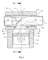
- Fig. 1 shows a prior art axial sealing element, similar to that disclosed in US Patent 5,526,780 (Wallis ), assembled into a rotary valve engine with a schematic steady state pressure distribution shown around it.
- prior art sealing element 31 is an axial sealing element with a constant rectangular cross section and parallel sides. Sealing element 31 is located in an axial slot 20 in the cylinder head bore 8, parallel to the axis of the rotary valve. Sealing element 31 is biased against the cylindrical portion 4 of the outside of the rotary valve by springs not shown. The force applied by these springs is indicated by arrow F.
- the clearances shown are exaggerated for the purposes of explaining the operation of the sealing element, and in practice the clearances are minimal.
- the pressure in the combustion chamber is indicated by P c and the flow of combustion gases into slot 20, through the clearance between the side of sealing element 31 and the side 35 of slot 20 closest to the combustion chamber window, as combustion pressure P c increases, is indicated by flow arrow 32.
- sealing element 31 seals the gap between cylinder head bore 8 and cylindrical portion 4 by being pressurised against cylindrical portion 4 and the side 33 of slot 20 furthest from the combustion chamber window.
- the surfaces of the sealing element, the slot and the outside diameter of the valve are not perfectly flat and smooth so there will be a small amount of leakage across the faces that are to be sealed. This allows the establishment of a pressure distribution on these surfaces opposing the closing force generated by the free access of gas to the surfaces opposite to the sealing surfaces.
- This pressure distribution is typically triangular in shape as is shown in Fig. 1 by the pressure distribution between sealing element 31 and cylindrical portion 4, and between sealing element 31 and the side 33 of slot 20 furthest from the combustion chamber window.
- P us is approximately equal to P c (as shown in Fig. 1 ) with the result that the sealing elements are adequately pressurised against the valve to seal successfully.
- P us on the underside of the sealing element may be inadequate to resist the combustion pressure and as a result, the sealing element may be forced away from the valve causing the sealing to fail.
- the volume underneath the sealing element determines the mass of gas that must be transported into this area in order to pressurise it.
- This volume acts as a capacitor and consequently the pressure P us on the underside of the sealing element lags the combustion pressure P c that the sealing element must seal against.
- the magnitude of this pressure lag is a function of the volume, the flow area feeding the volume, the radial depth of the sealing element, and the engine speed.
- the pressure lag increases when engine speed, volume or radial depth increases, or flow area decreases.
- the flow area is proportional to the side clearance of the sealing element in its slot, which is generally kept to an absolute minimum consistent with the sealing element always being free to move. This minimises the crevice volume and the fore and aft movement of the sealing element in its slot.
- the gas velocity through this side clearance is proportional to the pressure lag but the velocity is limited to Mach 1, which is when the flow becomes choked.
- Fig. 2 is the same as Fig. 1 except with a pressure lag as described above.
- the pressure lag is graphically indicated by the magnitude of P us being significantly less than P c . It can be easily demonstrated that in order for sealing element 31 to remain preloaded against cylindrical portion 4 the following condition must be true. P us > 0.5 P c - F / A
- the pressure lag will increase with increasing engine speed until a point is reached where this condition is no longer true and the force acting on the top face of the sealing element exceeds that acting on its underside.
- the engine speed at which this occurs will be a function of the sealing element side clearance, radial depth and the volume underneath the sealing element.
- a sealing element may be forced into contact with the side of its slot that is closest to the combustion chamber window.
- a typical example of this is the leading axial sealing element.
- Another situation where this occurs is when the engine is running at closed throttle and a high vacuum exists in the cylinder, which tends to pull the sealing elements inwards against the sides of their slots closest to the window. In these situations the rising cylinder pressure during compression and combustion must first push the sealing element away from its slot side closest to the window, before gas flow can commence between the sealing element and the slot side to the underside of the sealing element.
- the present invention seeks to provide a sealing element that at least ameliorates some of the problems of the prior art.
- the present invention consists of a gas sealing element for a rotary valve internal combustion engine, said engine comprising a cylinder head having a bore, a rotary valve rotatable within said bore with a predetermined clearance, and a window in said bore communicating with a combustion chamber, said sealing element having an elongate form and having a sealing face, an underside opposite said sealing face, and first and second side faces opposite each other, said sealing element being adapted to be located in a slot in said bore adjacent to said window, with said first side face adjacent to the side of said slot closest to said window, and with said sealing face being biased against said valve, characterised in that said first side face has at least one channel disposed therein extending from said sealing face to said underside.
- said gas sealing element is adapted to be one of an array of floating seals surrounding said window.
- said at least one channel is a plurality of spaced apart channels.
- said channel is a recess substantially parallel to said first side face.
- said gas sealing element is adapted to be disposed substantially parallel to the axis of said bore.
- the width of said sealing element, between said side faces, is less than its depth.
- said at least one channel lies within the axial extremities of said window.
- said gas sealing element is substantially arcuate and adapted to be disposed in a plane substantially perpendicular to the axis of said bore.
- said at least one channel lies within the circumferential extremities of said window.
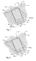
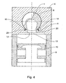
- Figs. 3 and 4 depict a rotary valve internal combustion engine having gas sealing elements 14 and 15 in accordance with the present invention.
- Cylinder head 6 is mounted on top of cylinder block 9, and piston 10 reciprocates within cylinder block 9.
- Axial flow rotary valve 1 is supported for rotation within bore 8 in cylinder head 6, about cylinder head bore axis 7, by bearings 5 with a small predetermined clearance between central cylindrical portion 4, on the outer surface of valve 1, and bore 8.
- Rotary valve 1 has an inlet port 2, and an exhaust port 3 terminating respectively at an inlet opening 21 and an exhaust opening 22 in cylindrical portion 4. As valve 1 rotates, inlet opening 21 and exhaust opening 22 periodically align with window 12 in bore 8, allowing the passage of gases between valve 1 and combustion chamber 13.
- US Patent 5,526,780 (Wallis ).
- the array of floating sealing elements comprises two axial sealing elements 15 and two circumferential sealing elements 14.
- Axial sealing elements 15 are disposed substantially parallel to bore axis 7, and are located in axial slots 20 adjacent to each side of window 12.
- Circumferential sealing elements 14 are located in circumferential slots 27 adjacent to each end of window 12.
- Each circumferential sealing element 14 lies in a respective plane substantially perpendicular to bore axis 7.
- each axial sealing element 15 is biased against cylindrical portion 4 by individual springs underneath both ends thereof.
- each circumferential sealing element 14 is biased against cylindrical portion 4 by a single elongate spring along the underside thereof.
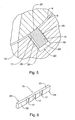
- axial sealing element 15 is straight and elongate with a rectangular cross section.
- Axial sealing element 15 has a sealing face 23, an underside 24 opposite sealing face 23, and side faces 25 and 26 opposite and parallel to each other.
- Side face 25 has three channels 17 disposed therein, each extending from sealing face 23 to underside 24.
- Channels 17 are in the form of shallow recesses substantially parallel to side face 25.
- the depth of channels 17 is small relative to the width of axial sealing element 15.
- channels 17 may for example each be approximately 0.1 mm deep and 3 to 5mm wide measured along the length of sealing element 15.
- the width of axial sealing element 15, measured between side faces 25 and 26, is preferably less than its depth, measured between sealing face 23 and underside 24.
- Channels 17 are substantially equally spaced apart and are positioned along the length of sealing element 15 such that when sealing element 15 is located in slot 20, channels 17 are all within the axial extremities of window 12.
- Axial sealing element 15 may be made from steel.
- axial sealing element 15 is located in axial slot 20 with side face 25, having channels 17, adjacent to the side 35 of slot 20 closest to window 12, and with side face 26 adjacent to the side 33 of slot 20 furthest from window 12.
- the clearance between the side faces 25 and 26 of axial sealing element 15 and slot 20 is as small as possible consistent with the sealing element always being free to move for the reasons given in the background. Sealing face 23 is biased against cylindrical portion 4.
- Channels 17 have two functions. Firstly, they provide sufficient flow area between axial sealing element 15 and slot side 35 closest to window 12 to ensure that the magnitude of the pressure lag between the combustion pressure P c and the pressure P us at the underside 24 of sealing element 15 is small enough that there is always a net force pushing sealing element 15 against cylindrical portion 4, even at high engine speeds. Secondly, channels 17 provide a flow path to the underside 24 of sealing element 15 if sealing element 15 is forced into contact with slot side 35 closest to window 12 by friction or vacuum as described in the background. Channels 17 then provide a greatly increased area for the gas pressure to act on to push sealing element 15 against the slot side 33 furthest from window 12.
- circumferential sealing element 14 is arcuate and elongate with a sealing face 28, an underside 29 opposite sealing face 28, and side faces 30 and 36 opposite and parallel to each other.
- Side face 30 has three channels 16 disposed therein, each extending from sealing face 28 to underside 29.
- channels 16 are in the form of shallow recesses substantially parallel to side face 30.
- Channels 16 have similar proportions to channels 17 in axial sealing element 15.
- Channels 16 are substantially equally spaced apart and are positioned along the length of sealing element 14 such that when sealing element 14 is located in circumferential slot 27, channels 16 are all within the circumferential extremities of window 12.
- Circumferential sealing element 14 may be made from steel.
- Circumferential sealing element 14 is located in circumferential slot 27 with side face 30, having channels 16, adjacent to the side of slot 27 closest to window 12.
- the clearance between the side faces 30 and 36 of circumferential sealing element 14 and slot 27 is as small as possible consistent with the sealing element always being free to move.
- Sealing face 28 is biased against cylindrical portion 4.
- Channels 16 serve the same purpose as channels 17, as described above.
- the number, depth and width of channels may vary depending on the details of the engine and its operating speed.
- the channels may have other shapes, rather than shallow recesses, as long as they provide a gas path from the sealing face to the underside of the sealing element.
- the preferred embodiments have the channels within the circumferential and axial extremities of the window this is not essential and in some applications the channels may be partially or wholly outside the extremities of the window.
Landscapes
- Engineering & Computer Science (AREA)
- Mechanical Engineering (AREA)
- General Engineering & Computer Science (AREA)
- Cylinder Crankcases Of Internal Combustion Engines (AREA)
- Valve Device For Special Equipments (AREA)
- Gasket Seals (AREA)
Applications Claiming Priority (2)
| Application Number | Priority Date | Filing Date | Title |
|---|---|---|---|
| AU2004904982A AU2004904982A0 (en) | 2004-09-01 | Gas sealing elements for a rotary valve | |
| PCT/AU2005/001309 WO2006024084A1 (en) | 2004-09-01 | 2005-08-31 | Gas sealing element for a rotary valve engine |
Publications (3)
| Publication Number | Publication Date |
|---|---|
| EP1802853A1 EP1802853A1 (en) | 2007-07-04 |
| EP1802853A4 EP1802853A4 (en) | 2010-07-07 |
| EP1802853B1 true EP1802853B1 (en) | 2012-10-10 |
Family
ID=35999626
Family Applications (1)
| Application Number | Title | Priority Date | Filing Date |
|---|---|---|---|
| EP05776084A Expired - Lifetime EP1802853B1 (en) | 2004-09-01 | 2005-08-31 | Gas sealing element for a rotary valve engine |
Country Status (5)
| Country | Link |
|---|---|
| US (1) | US7458357B2 (enExample) |
| EP (1) | EP1802853B1 (enExample) |
| JP (1) | JP2008511780A (enExample) |
| AU (1) | AU2005279693B2 (enExample) |
| WO (1) | WO2006024084A1 (enExample) |
Families Citing this family (1)
| Publication number | Priority date | Publication date | Assignee | Title |
|---|---|---|---|---|
| US7401587B2 (en) * | 2004-09-01 | 2008-07-22 | Bishop Innovation Limited | Gas and oil sealing in a rotary valve |
Family Cites Families (11)
| Publication number | Priority date | Publication date | Assignee | Title |
|---|---|---|---|---|
| GB1481803A (en) * | 1973-09-07 | 1977-08-03 | Cross Mfg Co | Lubrication of rotatable members |
| US4019487A (en) * | 1975-11-26 | 1977-04-26 | Dana Corporation | Rotary valve seal assembly |
| US4444161A (en) * | 1980-03-21 | 1984-04-24 | Williams Thomas V | Rotary valve for inherently balanced engine |
| AU586459B2 (en) | 1986-01-23 | 1989-07-13 | Arthur Ernest Bishop | Rotary valve for internal combustion engines |
| IT1225433B (it) * | 1988-10-26 | 1990-11-13 | Giancarlo Brusutti | Elemento di tenuta per distributore rotante di motori a combustione interna. |
| JPH0378509A (ja) * | 1989-08-18 | 1991-04-03 | Katsuo Tomita | 回転弁および気密シートおよびその潤滑方法 |
| JPH07103811B2 (ja) * | 1989-10-20 | 1995-11-08 | 巧 室木 | シール材をケーシング側に設けたロータリー弁装置 |
| AU668625B2 (en) * | 1992-11-06 | 1996-05-09 | Bishop Innovation Limited | Rotary valve with seal supporting tongue |
| JP3287846B2 (ja) * | 1992-11-06 | 2002-06-04 | エイ イー ビショップ リサーチ プロプライエタリー リミテッド | 回転弁用ガス密封システム |
| WO1994011620A1 (en) * | 1992-11-06 | 1994-05-26 | A.E. Bishop Research Pty. Limited | Lubrication system for rotary valve |
| US6578538B2 (en) * | 2001-04-02 | 2003-06-17 | O. Paul Trentham | Rotary valve for piston engine |
-
2005
- 2005-08-31 US US11/659,694 patent/US7458357B2/en not_active Expired - Fee Related
- 2005-08-31 JP JP2007528517A patent/JP2008511780A/ja active Pending
- 2005-08-31 WO PCT/AU2005/001309 patent/WO2006024084A1/en not_active Ceased
- 2005-08-31 EP EP05776084A patent/EP1802853B1/en not_active Expired - Lifetime
- 2005-08-31 AU AU2005279693A patent/AU2005279693B2/en not_active Expired - Fee Related
Also Published As
| Publication number | Publication date |
|---|---|
| WO2006024084A1 (en) | 2006-03-09 |
| US20070266985A1 (en) | 2007-11-22 |
| EP1802853A4 (en) | 2010-07-07 |
| AU2005279693B2 (en) | 2008-11-20 |
| US7458357B2 (en) | 2008-12-02 |
| AU2005279693A1 (en) | 2006-03-09 |
| JP2008511780A (ja) | 2008-04-17 |
| EP1802853A1 (en) | 2007-07-04 |
Similar Documents
| Publication | Publication Date | Title |
|---|---|---|
| US5222879A (en) | Contact-less seal and method for making same | |
| US6196550B1 (en) | Pressure balanced finger seal | |
| US6364316B1 (en) | Dual pressure balanced noncontacting finger seal | |
| JP2755910B2 (ja) | ロッドシール又はピストンシール | |
| EP2444701B1 (en) | Shaft seal device | |
| KR100348937B1 (ko) | 샤프트밀봉부 | |
| EP0499370A1 (en) | Mechanical face seals | |
| US5127661A (en) | Fluid seal | |
| US5169162A (en) | Piston ring having a function which is for facilitating supply of lubricating oil into an annular groove of a piston | |
| EP3619403B1 (en) | Improved circumferential seal assembly with adjustable seating forces | |
| KR101015783B1 (ko) | 연료 분배 시스템을 위한 캠 링 베어링 | |
| US6139290A (en) | Method to seal a planetary rotor engine | |
| AU668623B2 (en) | Sealing means for rotary valves | |
| AU2020202496B2 (en) | Annular sealing assembly | |
| EP1802853B1 (en) | Gas sealing element for a rotary valve engine | |
| US20080072866A1 (en) | Port Sealing In A Rotary Valve | |
| EP3726102B1 (en) | Annular sealing assembly | |
| EP1646815B1 (en) | Improvements relating to non-contacting face seals and thrust bearings | |
| EP4278071B1 (en) | Circumferential seal assembly with adjustable seating forces | |
| US4931001A (en) | Apex seal with filled aperture | |
| JPS59215987A (ja) | 回転圧縮機 | |
| JPS63176873A (ja) | シ−ル装置 |
Legal Events
| Date | Code | Title | Description |
|---|---|---|---|
| PUAI | Public reference made under article 153(3) epc to a published international application that has entered the european phase |
Free format text: ORIGINAL CODE: 0009012 |
|
| 17P | Request for examination filed |
Effective date: 20070221 |
|
| AK | Designated contracting states |
Kind code of ref document: A1 Designated state(s): DE FR GB IT |
|
| DAX | Request for extension of the european patent (deleted) | ||
| RBV | Designated contracting states (corrected) |
Designated state(s): DE FR GB IT |
|
| A4 | Supplementary search report drawn up and despatched |
Effective date: 20100608 |
|
| GRAP | Despatch of communication of intention to grant a patent |
Free format text: ORIGINAL CODE: EPIDOSNIGR1 |
|
| RAP1 | Party data changed (applicant data changed or rights of an application transferred) |
Owner name: BRV PTY LIMITED |
|
| GRAS | Grant fee paid |
Free format text: ORIGINAL CODE: EPIDOSNIGR3 |
|
| GRAA | (expected) grant |
Free format text: ORIGINAL CODE: 0009210 |
|
| AK | Designated contracting states |
Kind code of ref document: B1 Designated state(s): DE FR GB IT |
|
| REG | Reference to a national code |
Ref country code: GB Ref legal event code: FG4D |
|
| REG | Reference to a national code |
Ref country code: DE Ref legal event code: R096 Ref document number: 602005036508 Country of ref document: DE Effective date: 20121206 |
|
| PLBE | No opposition filed within time limit |
Free format text: ORIGINAL CODE: 0009261 |
|
| STAA | Information on the status of an ep patent application or granted ep patent |
Free format text: STATUS: NO OPPOSITION FILED WITHIN TIME LIMIT |
|
| PG25 | Lapsed in a contracting state [announced via postgrant information from national office to epo] |
Ref country code: IT Free format text: LAPSE BECAUSE OF FAILURE TO SUBMIT A TRANSLATION OF THE DESCRIPTION OR TO PAY THE FEE WITHIN THE PRESCRIBED TIME-LIMIT Effective date: 20121010 |
|
| 26N | No opposition filed |
Effective date: 20130711 |
|
| REG | Reference to a national code |
Ref country code: DE Ref legal event code: R097 Ref document number: 602005036508 Country of ref document: DE Effective date: 20130711 |
|
| GBPC | Gb: european patent ceased through non-payment of renewal fee |
Effective date: 20130831 |
|
| REG | Reference to a national code |
Ref country code: FR Ref legal event code: ST Effective date: 20140430 |
|
| PG25 | Lapsed in a contracting state [announced via postgrant information from national office to epo] |
Ref country code: GB Free format text: LAPSE BECAUSE OF NON-PAYMENT OF DUE FEES Effective date: 20130831 |
|
| PG25 | Lapsed in a contracting state [announced via postgrant information from national office to epo] |
Ref country code: FR Free format text: LAPSE BECAUSE OF NON-PAYMENT OF DUE FEES Effective date: 20130902 |
|
| PGFP | Annual fee paid to national office [announced via postgrant information from national office to epo] |
Ref country code: DE Payment date: 20200901 Year of fee payment: 16 |
|
| REG | Reference to a national code |
Ref country code: DE Ref legal event code: R119 Ref document number: 602005036508 Country of ref document: DE |
|
| PG25 | Lapsed in a contracting state [announced via postgrant information from national office to epo] |
Ref country code: DE Free format text: LAPSE BECAUSE OF NON-PAYMENT OF DUE FEES Effective date: 20220301 |