EP1802015A1 - Removing delay fluctuation in network time synchronization - Google Patents
Removing delay fluctuation in network time synchronization Download PDFInfo
- Publication number
- EP1802015A1 EP1802015A1 EP06255844A EP06255844A EP1802015A1 EP 1802015 A1 EP1802015 A1 EP 1802015A1 EP 06255844 A EP06255844 A EP 06255844A EP 06255844 A EP06255844 A EP 06255844A EP 1802015 A1 EP1802015 A1 EP 1802015A1
- Authority
- EP
- European Patent Office
- Prior art keywords
- delay
- network
- time synchronization
- timing packet
- timing
- Prior art date
- Legal status (The legal status is an assumption and is not a legal conclusion. Google has not performed a legal analysis and makes no representation as to the accuracy of the status listed.)
- Withdrawn
Links
Images

Classifications
-
- G—PHYSICS
- G06—COMPUTING OR CALCULATING; COUNTING
- G06F—ELECTRIC DIGITAL DATA PROCESSING
- G06F1/00—Details not covered by groups G06F3/00 - G06F13/00 and G06F21/00
- G06F1/04—Generating or distributing clock signals or signals derived directly therefrom
- G06F1/14—Time supervision arrangements, e.g. real time clock
-
- H—ELECTRICITY
- H04—ELECTRIC COMMUNICATION TECHNIQUE
- H04J—MULTIPLEX COMMUNICATION
- H04J3/00—Time-division multiplex systems
- H04J3/02—Details
- H04J3/06—Synchronising arrangements
- H04J3/0635—Clock or time synchronisation in a network
- H04J3/0638—Clock or time synchronisation among nodes; Internode synchronisation
- H04J3/0658—Clock or time synchronisation among packet nodes
- H04J3/0661—Clock or time synchronisation among packet nodes using timestamps
- H04J3/0667—Bidirectional timestamps, e.g. NTP or PTP for compensation of clock drift and for compensation of propagation delays
-
- H—ELECTRICITY
- H04—ELECTRIC COMMUNICATION TECHNIQUE
- H04L—TRANSMISSION OF DIGITAL INFORMATION, e.g. TELEGRAPHIC COMMUNICATION
- H04L43/00—Arrangements for monitoring or testing data switching networks
- H04L43/08—Monitoring or testing based on specific metrics, e.g. QoS, energy consumption or environmental parameters
- H04L43/0852—Delays
- H04L43/0858—One way delays
-
- H—ELECTRICITY
- H04—ELECTRIC COMMUNICATION TECHNIQUE
- H04L—TRANSMISSION OF DIGITAL INFORMATION, e.g. TELEGRAPHIC COMMUNICATION
- H04L43/00—Arrangements for monitoring or testing data switching networks
- H04L43/16—Threshold monitoring
-
- H—ELECTRICITY
- H04—ELECTRIC COMMUNICATION TECHNIQUE
- H04L—TRANSMISSION OF DIGITAL INFORMATION, e.g. TELEGRAPHIC COMMUNICATION
- H04L43/00—Arrangements for monitoring or testing data switching networks
- H04L43/10—Active monitoring, e.g. heartbeat, ping or trace-route
- H04L43/106—Active monitoring, e.g. heartbeat, ping or trace-route using time related information in packets, e.g. by adding timestamps
Definitions
- a wide variety of devices may include a local clock that maintains a time-of-day.
- Examples devices that may have a local time-of-day clock include computer systems, test instruments, industrial control devices, environmental control devices, and home appliances.
- a time synchronization protocol may be used to synchronize a local clock in a device.
- a time synchronization protocol may be one in which a local clock exchanges timing packets with a reference clock via a communication network. The transmit and receive times of the timing packets may be used to determine a time offset between a local clock and a reference clock so that the local clock may be adjusted to match the time in the reference clock.
- One example of a time synchronization protocol that includes the exchange of timing packets is the IEEE 1588 time synchronization protocol.
- NTP network time protocol
- a time offset that is derived from the exchange of timing packets may include a network delay associated with the transfer of the timing packet over a communication network.
- the network delay may be removed from a time offset before applying the time offset to a local clock. For example, a running average of the network delays for a series of timing packets may be determined and the running average may be subtracted from the time offset calculations.
- the network delays of timing packets may fluctuate in response to changes in network conditions. For example, a timing packet transferred during a period of relatively high network traffic may experience a much larger network delay than a timing packet transferred during a period of relatively low network traffic. Fluctuations in network delay may reduce the precision of a time synchronization protocol. For example, timing packets having a network delay that significantly exceeds a running average of network delays may cause an unneeded adjustment to a local clock.
- Time synchronization includes measuring a network delay associated with a timing packet and discarding the timing packet if the network delay exceeds an adjustable threshold.
- the adjustable threshold enables balancing the quality of delay measurements in terms of delay fluctuation against the number of delay measurements that are sufficient to maintain time synchronization.
- Figure 1 shows a pair of devices 10 and 12 that include mechanisms for removing delay fluctuations in network time synchronization according to the present teachings.
- Example embodiments of the devices 10 and 12 include computer systems, test instruments, industrial control devices, environmental control devices, home appliances, etc.
- the device 10 includes a local clock 14 and the device 12 includes a local clock 16.
- the devices 10 and 12 include respective time synchronization circuits 40 and 42 that maintain time synchronization in the local clocks 14 and 16 by exchanging timing packets via a communication network 30, e.g. a set of timing packets 20-22.
- the time synchronization circuits 40 and 42 maintain time synchronization according to the IEEE 1588 time synchronization protocol.
- the time synchronization circuit 42 adjusts the time-of-day in the local clock 16 to conform to the time-of-day held in the local clock 14 of the device 10, i.e. the local clock 14 is a master clock and the local clock 16 is a slave clock.
- the time synchronization circuit 40 generates the timing packet 20 and transfers it to the time synchronization circuit 42 via the communication network 30 and the time synchronization circuit 42 generates the timing packet 22 and transfers it to the time synchronization circuit 40 via the communication network 30.
- the time synchronization circuit 40 measures a transmit time (T1) of the timing packet 20 and the time synchronization circuit 42 measures a receive time (T2) of the timing packet 20.
- the time synchronization circuit 42 measures a transmit time (T3) of the timing packet 22 and the time synchronization circuit 40 measures a receive time (T4) of the timing packet 22.
- a time offset (OFFSET) to be applied to the local clock 16 is derived from the time-stamps T1-T4 (according to the IEEE 1588 time synchronization protocol in one embodiment)
- the network delay of the timing packet 20, i.e. the network delay from master to slave (MSD) is assumed to be equal to the network delay of the timing packet 22, i.e. the network delay from slave to master (SMD).
- Equation 1 shows that the time offset to be applied to the local clock 16 is a function of the network delay experienced by a timing packet carried via the communication network 30 between the devices 10 and 12. It is likely that the network delay experienced by a timing packet will fluctuate depending on the amount of network traffic underway.
- the communication network 30 may handle traffic for other devices (not shown) or may handle data packets for application-specific functions of the devices 10 and 12 that are not timing packets. High volumes of network traffic at times may cause some of the timing packets exchanged by the devices 10 and 12 to experience inordinately long delays.
- a timing packet may experience a substantially higher delay by waiting in a queue in a communication switch of the communication network 30 during a period of high traffic volume.
- a queuing delay imposed on a timing packet may cause an inordinately large time offset to be applied to the local clock 16 according to equation 1.
- a time offset yielded by an excessively delayed timing packet may degrade the accuracy in the time synchronization of the local clock 16.
- the present techniques for removing network delay fluctuations include discarding timing packets that have experienced excessively high network delay using an adjustable threshold of excessive delay.
- the discarding of timing packets that experience an excessive network delay avoids unneeded time adjustments to the local clock 16.
- equation 2 may be used to determine the network delay of a timing packet so that the timing packet may be discarded if its network delay is substantially larger than the network delay associated with timing packets exchanged by the devices 10 and 12 that do not experience excessive network delay. If a timing packet is discarded then the timing information derived from the timing packet is not used to determine a time offset to be applied to the local clock 16.
- the time-of-day held in the local clock 16 may advance relatively smoothly. In such embodiments, once a time synchronization servo settles it need not follow excursions accurately.
- the updates to the local clock 16 may be of relatively low bandwidth and still maintain adequate time synchronization. Therefore, the balance between the quality of delay measurements and the number of delay measurements may be tipped toward higher quality and fewer delay measurements.
- Timing packets occasionally encounter a path through the communication network 30 with no queuing delays. All timing packets that take that path have substantially similar amounts of network delay. Timing packets that are queued have a much larger network delay than the network delay experienced by timing packets having no queuing delay so that timing packets that are queued may be recognized.
- the devices 10 and 12 include respective communication subsystems that are adapted for communication via the communication link 30 and that enable the time synchronization circuits 40 and 42 to exchange timing packets via the communication link 30.
- the communication subsystems may include media access controller, (MAC) and physical interface (PHY) elements, etc., depending on the implementation of the communication network 30.
- the time synchronization circuits 40 and 42 may include processor subsystems that implement a network protocol stack and that generate timing packets and that obtain timing information from timing packet.
- the time synchronization circuits 40 and 42 may also include time packet recognizer circuitry for recognizing and time stamping inbound and outbound timing packets.
- Figure 2 shows a method for removing delay fluctuations in network time synchronization according to the present teachings.
- the method step shown may be used to determine a minimum network delay path for a timing packet carried on the communication network 30 between the device 10 and 12 so that timing packets exchanged by the devices 10 and 12 having excessive delay may be selected and discarded.
- the minimum network delay is represented by the variable delta.
- An adjustable threshold of epsilon includes the expected network delay jitter on the communication network 30 without queuing delays.
- a relatively large initial value is chosen for delta.
- An example of a large initial value for delta is an estimate of the time for sending a timing packet around the world via a network.
- the timing information associated with an incoming timing packet e.g. measured and/or transported time stamps, is used to determine a network delay between the devices 10 and 12.
- the network delay determined at step 100 is the round-trip network delay.
- the network delay at step 100 may be determined according to IEEE 1588 calculations or NTP calculations or other similar time synchronization protocol depending on a particular embodiment.
- step 102 if the network delay from step 100 is greater than delta + epsilon, then the corresponding timing packet is discarded, i.e. ignored and not used in determining a time offset to be used in adjusting the local clock 16.
- delta is set to an average of the previous value of delta and the network delay from step 100.
- Any running average may be used, e.g. exponential averaging.
- step 106 if the network delay from step 100 is smaller than delta - epsilon, then the previously computed running average, if any, is discarded and delta is set to the network delay from step 100.
- the discarding of timing packets having an excessive network delay reduces the number of timing packets available for time synchronization.
- the present techniques include controlling the discarding of timing packets using the adjustable threshold so that the quality of delay measurements may be balanced against the number of measurements needed given the capability of the local clock 16 in maintaining time synchronization in the absence of time updates.
- the path taken by a timing packet through the communication network 30 may be represented as a series of queues, i.e. a series of i delay elements each having a delay distribution with a practical minimum.
- the delay elements may be regarded as mutually independent and as having substantially similar delay distributions.
- the delay introduced by each delay element averaged over an acceptable time between delay estimates is d1, d2...dn.
- the value of epsilon may be adjusted by adding d1 to it, and then adding d2 to it, and then adding d3 to it, etc., until the probability of the remaining n-i elements simultaneously introducing their minimum delay is sufficiently large, i.e. the expected time between timing packets that are not discarded is sufficiently small.
- the above technique for subdividing the largest network delay in timing packet transfer provides a set of control steps in an adjustable threshold.
- the number of control steps used for the adjustable threshold may depend on how efficiently the local clock 16 coasts, i.e. on how frequently time updates to the local clock 16 are needed to maintain sufficient synchronization.
- Each instance may have a different value of i, and different weights may be assigned to the network delay estimates yielded by the instances.
- a time offset to be applied the local clock 16 is determined in response to each incoming timing packet received via the communication network 30. If a time offset is relatively large, i.e. significantly greater than epsilon, then it may be assumed that the large time offset is a result of excessive network delay in a timing packet rather than a sudden erratic behavior of the local clock 16 that requires correction. Therefore, the inordinately large time adjustments may be discarded.
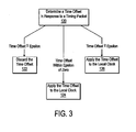
- Figure 3 shows a method for removing fluctuations from time offset adjustments to be applied to the local clock 16 according to the present teachings.
- the initial value for epsilon is an estimate of the expected time offset fluctuation for timing packets that are not delayed.
- the initial value for epsilon may the standard deviation of time offsets from the timing packets which have been used so far for time synchronization. For the first one or two timing packets this may be a very large value.
- a time offset is determined in response to a timing packet. For example, a time offset may be determined using equation 1 above.
- step 122 if the absolute value of the time offset from step 120 is algebraically larger than epsilon, then the timing packet is ignored and the time offset is discarded.
- step 124 if the time offset from step 120 is within epsilon of 0, then the time offset is applied to the local clock 16.
- step 126 if the absolute value of the time offset from step 120 is algebraically smaller than epsilon, then any previously-computed running average is discarded and the time offset is applied to the local clock 16.
- the timing packets that are discarded may include information that is useful in time synchronization.
- the timing packets that are subject to queuing delay may be characterized by a collective distribution, e.g. a Poisson distribution, which may be time-varying depending on the traffic on the communication network 30.
- the distribution may be modeled as a member of a family of distributions with a finite number (e.g. 1) of parameters.
- the network delay experienced by all of the timing packets including those discarded may be used to estimate the parameters and formulate a prediction of the time until the next usable timing packet in terms of network delay.
- an appropriate action may be taken.
- One example of an action is to change the value of i in the series of delay elements discussed above. The value of i may be changed back when statistics improve.
- Another example of an action is to temporarily request forward or reverse time synchronization measurements at an increased rate. Reverse measurements are performed by the device 12 having the local clock 16. For forward measurements, the available actions depend on the clock synchronization protocol. In NTP, forward timing packets are always requested by the slave. In IEEE 1588 time synchronization, the slave may request an additional or an earlier reverse measurement.
- Another example of an action is to use past statistics of accepted timing packets to extrapolate a time offset. This is a normal operation in IEEE 1588 time synchronization given that delay timing packets arrive less often than synchronization timing packets.
- This prediction can be used to choose an optimum value for epsilon.
- the modeled distribution may state that there is 95% confidence that a timing packet with queuing delay less than epsilon will arrive within any 30 second interval. If the local clock can coast for 30 seconds with the desired accuracy, then epsilon is large enough. If the clock can only coast accurately for 10 seconds, then epsilon may be increased until the model predicts that, with 95% confidence, a usable packet will arrive within 10 seconds. Similarly, the model may be used to choose an epsilon such that there is a 99% probability that a usable packet will arrive within the desired interval.
Landscapes
- Engineering & Computer Science (AREA)
- Computer Networks & Wireless Communication (AREA)
- Signal Processing (AREA)
- Theoretical Computer Science (AREA)
- Environmental & Geological Engineering (AREA)
- Physics & Mathematics (AREA)
- General Engineering & Computer Science (AREA)
- General Physics & Mathematics (AREA)
- Synchronisation In Digital Transmission Systems (AREA)
- Data Exchanges In Wide-Area Networks (AREA)
Abstract
Description
- A wide variety of devices may include a local clock that maintains a time-of-day. Examples devices that may have a local time-of-day clock include computer systems, test instruments, industrial control devices, environmental control devices, and home appliances.
- A time synchronization protocol may be used to synchronize a local clock in a device. A time synchronization protocol may be one in which a local clock exchanges timing packets with a reference clock via a communication network. The transmit and receive times of the timing packets may be used to determine a time offset between a local clock and a reference clock so that the local clock may be adjusted to match the time in the reference clock. One example of a time synchronization protocol that includes the exchange of timing packets is the IEEE 1588 time synchronization protocol. Another example is the network time protocol (NTP).
- A time offset that is derived from the exchange of timing packets may include a network delay associated with the transfer of the timing packet over a communication network. The network delay may be removed from a time offset before applying the time offset to a local clock. For example, a running average of the network delays for a series of timing packets may be determined and the running average may be subtracted from the time offset calculations.
- The network delays of timing packets may fluctuate in response to changes in network conditions. For example, a timing packet transferred during a period of relatively high network traffic may experience a much larger network delay than a timing packet transferred during a period of relatively low network traffic. Fluctuations in network delay may reduce the precision of a time synchronization protocol. For example, timing packets having a network delay that significantly exceeds a running average of network delays may cause an unneeded adjustment to a local clock.
- Techniques are disclosed for removing delay fluctuations from network time synchronization so that timing packets that experience an inordinate network delay to not cause unneeded adjustments to a local clock. Time synchronization according to the present techniques includes measuring a network delay associated with a timing packet and discarding the timing packet if the network delay exceeds an adjustable threshold. The adjustable threshold enables balancing the quality of delay measurements in terms of delay fluctuation against the number of delay measurements that are sufficient to maintain time synchronization.
- Other features and advantages of the present invention will be apparent from the detailed description that follows.
- The present invention is described with respect to particular exemplary embodiments thereof and reference is accordingly made to the drawings in which:
- Figure 1 shows a pair of devices that include mechanisms for removing delay fluctuations in network time synchronization according to the present teachings;
- Figure 2 shows a method for removing delay fluctuations in network time synchronization according to the present teachings;
- Figure 3 shows a method for removing fluctuations from time offset adjustments according to the present teachings.
- Figure 1 shows a pair of
devices devices - The
device 10 includes alocal clock 14 and thedevice 12 includes alocal clock 16. Thedevices time synchronization circuits local clocks communication network 30, e.g. a set of timing packets 20-22. - In one embodiment, the
time synchronization circuits time synchronization circuit 42 adjusts the time-of-day in thelocal clock 16 to conform to the time-of-day held in thelocal clock 14 of thedevice 10, i.e. thelocal clock 14 is a master clock and thelocal clock 16 is a slave clock. - For example, the
time synchronization circuit 40 generates thetiming packet 20 and transfers it to thetime synchronization circuit 42 via thecommunication network 30 and thetime synchronization circuit 42 generates thetiming packet 22 and transfers it to thetime synchronization circuit 40 via thecommunication network 30. Thetime synchronization circuit 40 measures a transmit time (T1) of thetiming packet 20 and thetime synchronization circuit 42 measures a receive time (T2) of thetiming packet 20. Similarly, thetime synchronization circuit 42 measures a transmit time (T3) of thetiming packet 22 and thetime synchronization circuit 40 measures a receive time (T4) of thetiming packet 22. A time offset (OFFSET) to be applied to thelocal clock 16 is derived from the time-stamps T1-T4 (according to the IEEE 1588 time synchronization protocol in one embodiment) - In one embodiment, the network delay of the
timing packet 20, i.e. the network delay from master to slave (MSD), is assumed to be equal to the network delay of thetiming packet 22, i.e. the network delay from slave to master (SMD). The time offset for thelocal clock 16 is as follows.
where
and
- Equation 1 shows that the time offset to be applied to the
local clock 16 is a function of the network delay experienced by a timing packet carried via thecommunication network 30 between thedevices communication network 30 may handle traffic for other devices (not shown) or may handle data packets for application-specific functions of thedevices devices communication network 30 during a period of high traffic volume. A queuing delay imposed on a timing packet may cause an inordinately large time offset to be applied to thelocal clock 16 according to equation 1. A time offset yielded by an excessively delayed timing packet may degrade the accuracy in the time synchronization of thelocal clock 16. - The present techniques for removing network delay fluctuations include discarding timing packets that have experienced excessively high network delay using an adjustable threshold of excessive delay. The discarding of timing packets that experience an excessive network delay avoids unneeded time adjustments to the
local clock 16. For example, equation 2 may be used to determine the network delay of a timing packet so that the timing packet may be discarded if its network delay is substantially larger than the network delay associated with timing packets exchanged by thedevices local clock 16. - In some embodiments, the time-of-day held in the
local clock 16 may advance relatively smoothly. In such embodiments, once a time synchronization servo settles it need not follow excursions accurately. The updates to thelocal clock 16 may be of relatively low bandwidth and still maintain adequate time synchronization. Therefore, the balance between the quality of delay measurements and the number of delay measurements may be tipped toward higher quality and fewer delay measurements. - Timing packets occasionally encounter a path through the
communication network 30 with no queuing delays. All timing packets that take that path have substantially similar amounts of network delay. Timing packets that are queued have a much larger network delay than the network delay experienced by timing packets having no queuing delay so that timing packets that are queued may be recognized. - The
devices communication link 30 and that enable thetime synchronization circuits communication link 30. For example, the communication subsystems may include media access controller, (MAC) and physical interface (PHY) elements, etc., depending on the implementation of thecommunication network 30. Thetime synchronization circuits time synchronization circuits - Figure 2 shows a method for removing delay fluctuations in network time synchronization according to the present teachings. The method step shown may be used to determine a minimum network delay path for a timing packet carried on the
communication network 30 between thedevice devices communication network 30 without queuing delays. - Initially, a relatively large initial value is chosen for delta. An example of a large initial value for delta is an estimate of the time for sending a timing packet around the world via a network.
- At
step 100, the timing information associated with an incoming timing packet, e.g. measured and/or transported time stamps, is used to determine a network delay between thedevices step 100 is the round-trip network delay. The network delay atstep 100 may be determined according to IEEE 1588 calculations or NTP calculations or other similar time synchronization protocol depending on a particular embodiment. - At
step 102, if the network delay fromstep 100 is greater than delta + epsilon, then the corresponding timing packet is discarded, i.e. ignored and not used in determining a time offset to be used in adjusting thelocal clock 16. - At step 104, if the network delay from
step 100 is within epsilon of delta, then delta is set to an average of the previous value of delta and the network delay fromstep 100. Any running average may be used, e.g. exponential averaging. - At
step 106, if the network delay fromstep 100 is smaller than delta - epsilon, then the previously computed running average, if any, is discarded and delta is set to the network delay fromstep 100. - The above process repeats with for each incoming timing packet.
- The discarding of timing packets having an excessive network delay reduces the number of timing packets available for time synchronization. The present techniques include controlling the discarding of timing packets using the adjustable threshold so that the quality of delay measurements may be balanced against the number of measurements needed given the capability of the
local clock 16 in maintaining time synchronization in the absence of time updates. - For example, the path taken by a timing packet through the
communication network 30 may be represented as a series of queues, i.e. a series of i delay elements each having a delay distribution with a practical minimum. The delay elements may be regarded as mutually independent and as having substantially similar delay distributions. The delay introduced by each delay element averaged over an acceptable time between delay estimates is d1, d2...dn. The value of epsilon may be adjusted by adding d1 to it, and then adding d2 to it, and then adding d3 to it, etc., until the probability of the remaining n-i elements simultaneously introducing their minimum delay is sufficiently large, i.e. the expected time between timing packets that are not discarded is sufficiently small. - It may not be known how many delay elements in a communication network cause significant delay. Given that the delay di is mapped onto values of epsilon, a smallest and largest delay fluctuation may be estimated and the span between the smallest and the largest may be partitioned into n ranges. This enables an adjustment of the balance between frequency and variance of the network delay corrections.
- The above technique for subdividing the largest network delay in timing packet transfer provides a set of control steps in an adjustable threshold. The number of control steps used for the adjustable threshold may depend on how efficiently the
local clock 16 coasts, i.e. on how frequently time updates to thelocal clock 16 are needed to maintain sufficient synchronization. - Several instances of a process embodying the steps 100-106 may be executed in parallel. Each instance may have a different value of i, and different weights may be assigned to the network delay estimates yielded by the instances. The instance with 1=1 will produce network delay estimates least often but with the highest weight. The instance with i=n will produce a network delay estimate for every incoming timing packet but with the lowest weight.
- A time offset to be applied the
local clock 16 is determined in response to each incoming timing packet received via thecommunication network 30. If a time offset is relatively large, i.e. significantly greater than epsilon, then it may be assumed that the large time offset is a result of excessive network delay in a timing packet rather than a sudden erratic behavior of thelocal clock 16 that requires correction. Therefore, the inordinately large time adjustments may be discarded. - Figure 3 shows a method for removing fluctuations from time offset adjustments to be applied to the
local clock 16 according to the present teachings. - Initially, a value for epsilon is selected. The initial value for epsilon is an estimate of the expected time offset fluctuation for timing packets that are not delayed. The initial value for epsilon may the standard deviation of time offsets from the timing packets which have been used so far for time synchronization. For the first one or two timing packets this may be a very large value.
- At
step 120, a time offset is determined in response to a timing packet. For example, a time offset may be determined using equation 1 above. - At
step 122, if the absolute value of the time offset fromstep 120 is algebraically larger than epsilon, then the timing packet is ignored and the time offset is discarded. - At
step 124, if the time offset fromstep 120 is within epsilon of 0, then the time offset is applied to thelocal clock 16. - At
step 126, if the absolute value of the time offset fromstep 120 is algebraically smaller than epsilon, then any previously-computed running average is discarded and the time offset is applied to thelocal clock 16. - The timing packets that are discarded may include information that is useful in time synchronization. The timing packets that are subject to queuing delay may be characterized by a collective distribution, e.g. a Poisson distribution, which may be time-varying depending on the traffic on the
communication network 30. The distribution may be modeled as a member of a family of distributions with a finite number (e.g. 1) of parameters. As a consequence, the network delay experienced by all of the timing packets including those discarded may be used to estimate the parameters and formulate a prediction of the time until the next usable timing packet in terms of network delay. - If the next timing packet that is not discarded is too far in the future, allowing for an imprecise parameter estimation, and an inexact prediction, an appropriate action may be taken. One example of an action is to change the value of i in the series of delay elements discussed above. The value of i may be changed back when statistics improve. Another example of an action is to temporarily request forward or reverse time synchronization measurements at an increased rate. Reverse measurements are performed by the
device 12 having thelocal clock 16. For forward measurements, the available actions depend on the clock synchronization protocol. In NTP, forward timing packets are always requested by the slave. In IEEE 1588 time synchronization, the slave may request an additional or an earlier reverse measurement. - Another example of an action is to use past statistics of accepted timing packets to extrapolate a time offset. This is a normal operation in IEEE 1588 time synchronization given that delay timing packets arrive less often than synchronization timing packets. This prediction can be used to choose an optimum value for epsilon. For example, the modeled distribution may state that there is 95% confidence that a timing packet with queuing delay less than epsilon will arrive within any 30 second interval. If the local clock can coast for 30 seconds with the desired accuracy, then epsilon is large enough. If the clock can only coast accurately for 10 seconds, then epsilon may be increased until the model predicts that, with 95% confidence, a usable packet will arrive within 10 seconds. Similarly, the model may be used to choose an epsilon such that there is a 99% probability that a usable packet will arrive within the desired interval.
- The foregoing detailed description of the present invention is provided for the purposes of illustration and is not intended to be exhaustive or to limit the invention to the precise embodiment disclosed. Accordingly, the scope of the present invention is defined by the appended claims.
Claims (10)
- A method for network time synchronization, comprising:measuring a network delay associated with a timing packet;discarding the timing packet if the network delay exceeds an adjustable threshold.
- The method of claim 1, wherein discarding the timing packet comprises determining a minimum network delay and discarding the timing packet if the network delay is greater than the minimum network delay by more than an adjustable amount.
- The method of claim 1, further comprising determining the adjustable threshold by determining a balance between a quality of delay measurement and a number of delay measurements that are sufficient for maintaining time synchronization.
- The method of claim 1, wherein discarding the timing packet comprises determining a plurality of estimates of the network delay and assigning a weight to each estimate.
- The method of claim 1, wherein discarding the timing packet comprises subdividing a delay range to provide a number of control steps in the adjustable threshold.
- The method of claim 1, further comprising determining a time offset in response to the timing packet and discarding the time offset if the network delay exceeds the adjustable threshold.
- A device with network time synchronization, comprising:local clock (16);time synchronization circuit (42) that receives a timing packet via a communication network and that determines a network delay in response to the timing packet and that discards the timing packet if the network delay exceeds an adjustable threshold.
- The device of claim 7, wherein the time synchronization circuit (42) determines a minimum network delay on the communication network and discards the timing packet if the network delay is greater than the minimum network delay by more than an adjustable amount.
- The device of claim 7, wherein the adjustable threshold provides a balance between a quality of delay measurement and a number of delay measurements that are sufficient for maintaining time synchronization.
- The device of claim 7, wherein the adjustable threshold is derived from a span of delay fluctuation in timing packet transfer.
Applications Claiming Priority (1)
| Application Number | Priority Date | Filing Date | Title |
|---|---|---|---|
| US11/317,711 US20070147435A1 (en) | 2005-12-23 | 2005-12-23 | Removing delay fluctuation in network time synchronization |
Publications (1)
| Publication Number | Publication Date |
|---|---|
| EP1802015A1 true EP1802015A1 (en) | 2007-06-27 |
Family
ID=37605688
Family Applications (1)
| Application Number | Title | Priority Date | Filing Date |
|---|---|---|---|
| EP06255844A Withdrawn EP1802015A1 (en) | 2005-12-23 | 2006-11-15 | Removing delay fluctuation in network time synchronization |
Country Status (4)
| Country | Link |
|---|---|
| US (1) | US20070147435A1 (en) |
| EP (1) | EP1802015A1 (en) |
| JP (1) | JP4884199B2 (en) |
| CN (1) | CN1997027A (en) |
Cited By (7)
| Publication number | Priority date | Publication date | Assignee | Title |
|---|---|---|---|---|
| EP2093915A1 (en) * | 2008-02-19 | 2009-08-26 | Abb Research Ltd. | Time synchronization in a network |
| EP2228927A1 (en) | 2009-03-12 | 2010-09-15 | Alcatel Lucent | Method for processing distributed data having a chosen type for synchronizing communication nodes of a data packet network, and associated device |
| EP2490357A3 (en) * | 2011-02-15 | 2012-10-31 | General Electric Company | A method of time synchronization of free running nodes in an avionics network |
| EP2426862A4 (en) * | 2009-04-29 | 2013-03-27 | Univ Madrid Autonoma | APPARATUS FOR THE CERTIFIED MEASUREMENT OF THE BANDWIDTH OF A NETWORK ACCESS AND METHOD OF CALIBRATING THE APPARATUS |
| CN103297288A (en) * | 2012-02-24 | 2013-09-11 | 富士通株式会社 | Packet transfer delay measurement system |
| WO2015024599A1 (en) * | 2013-08-22 | 2015-02-26 | Telefonaktiebolaget L M Ericsson (Publ) | A method for detecting timing references affected by a change in path delay asymmetry between nodes in a communications network |
| AT518006A1 (en) * | 2015-11-20 | 2017-06-15 | Sprecher Automation Gmbh | Method for the synchronized detection of measured data required for controlling differential protective devices of electrical power lines |
Families Citing this family (82)
| Publication number | Priority date | Publication date | Assignee | Title |
|---|---|---|---|---|
| US7711008B2 (en) * | 2006-01-23 | 2010-05-04 | Ipwireless, Inc. | Quasi synchronous transmission in cellular networks |
| US9843489B2 (en) * | 2013-06-12 | 2017-12-12 | Blackfire Research Corporation | System and method for synchronous media rendering over wireless networks with wireless performance monitoring |
| WO2008024818A2 (en) * | 2006-08-22 | 2008-02-28 | Brilliant Telecommunications, Inc. | Apparatus and method of controlled delay packet forwarding |
| EP2297886B1 (en) * | 2008-06-02 | 2013-02-20 | TTTech Computertechnik AG | Method for synchronizing local clocks in a distributed computer network |
| JP4572976B2 (en) * | 2008-09-26 | 2010-11-04 | ブラザー工業株式会社 | Communication device and communication program |
| CN101729180A (en) * | 2008-10-21 | 2010-06-09 | 华为技术有限公司 | Method and system for synchronizing precision clocks, and precision clock frequency/time synchronizing device |
| JP5440880B2 (en) | 2008-11-20 | 2014-03-12 | 日本電気株式会社 | Clock synchronization system, apparatus, method, and program using packet filter |
| JP2010135880A (en) * | 2008-12-02 | 2010-06-17 | Hitachi Ltd | Clock synchronization system and clock synchronization method |
| US20100165839A1 (en) * | 2008-12-29 | 2010-07-01 | Motorola, Inc. | Anti-replay method for unicast and multicast ipsec |
| CN101783779B (en) * | 2009-01-16 | 2014-07-16 | 华为技术有限公司 | Time synchronization method, device and system of xDSL |
| DE102009015920B4 (en) | 2009-03-25 | 2014-11-20 | Faro Technologies, Inc. | Device for optically scanning and measuring an environment |
| US9551575B2 (en) | 2009-03-25 | 2017-01-24 | Faro Technologies, Inc. | Laser scanner having a multi-color light source and real-time color receiver |
| US8031747B2 (en) | 2009-04-29 | 2011-10-04 | Juniper Networks, Inc. | Apparatus and method of compensating for clock frequency and phase variations by processing packet delay values |
| EP2282427B1 (en) * | 2009-07-31 | 2015-03-04 | Alcatel Lucent | Method for synchronizing a client clock frequency with a server clock frequency |
| US8966110B2 (en) * | 2009-09-14 | 2015-02-24 | International Business Machines Corporation | Dynamic bandwidth throttling |
| US9529083B2 (en) | 2009-11-20 | 2016-12-27 | Faro Technologies, Inc. | Three-dimensional scanner with enhanced spectroscopic energy detector |
| US9113023B2 (en) | 2009-11-20 | 2015-08-18 | Faro Technologies, Inc. | Three-dimensional scanner with spectroscopic energy detector |
| DE102009057101A1 (en) | 2009-11-20 | 2011-05-26 | Faro Technologies, Inc., Lake Mary | Device for optically scanning and measuring an environment |
| US9210288B2 (en) | 2009-11-20 | 2015-12-08 | Faro Technologies, Inc. | Three-dimensional scanner with dichroic beam splitters to capture a variety of signals |
| US8670459B2 (en) * | 2009-11-30 | 2014-03-11 | Juniper Networks, Inc. | Apparatus and method of scheduling timing packets to enhance time distribution in telecommunication networks |
| CN102111258A (en) * | 2009-12-25 | 2011-06-29 | 华为技术有限公司 | Clock synchronization method, equipment and system |
| RU2503134C1 (en) * | 2009-12-31 | 2013-12-27 | Абб Рисерч Лтд. | Method and apparatus for detecting communication channel delay asymmetry |
| US8630314B2 (en) | 2010-01-11 | 2014-01-14 | Faro Technologies, Inc. | Method and apparatus for synchronizing measurements taken by multiple metrology devices |
| US8638446B2 (en) | 2010-01-20 | 2014-01-28 | Faro Technologies, Inc. | Laser scanner or laser tracker having a projector |
| US9628775B2 (en) | 2010-01-20 | 2017-04-18 | Faro Technologies, Inc. | Articulated arm coordinate measurement machine having a 2D camera and method of obtaining 3D representations |
| US8832954B2 (en) | 2010-01-20 | 2014-09-16 | Faro Technologies, Inc. | Coordinate measurement machines with removable accessories |
| GB2489135B (en) | 2010-01-20 | 2013-10-09 | Faro Tech Inc | Display for coordinate measuring machine |
| DE112011100294B4 (en) | 2010-01-20 | 2019-06-13 | Faro Technologies Inc. | Portable articulated arm coordinate measuring machine with multibus arm technology |
| US8875409B2 (en) | 2010-01-20 | 2014-11-04 | Faro Technologies, Inc. | Coordinate measurement machines with removable accessories |
| US9607239B2 (en) | 2010-01-20 | 2017-03-28 | Faro Technologies, Inc. | Articulated arm coordinate measurement machine having a 2D camera and method of obtaining 3D representations |
| US8615893B2 (en) | 2010-01-20 | 2013-12-31 | Faro Technologies, Inc. | Portable articulated arm coordinate measuring machine having integrated software controls |
| CN102782442A (en) | 2010-01-20 | 2012-11-14 | 法罗技术股份有限公司 | Coordinate measuring machine with illuminated stylus tip and method of operation |
| US8677643B2 (en) | 2010-01-20 | 2014-03-25 | Faro Technologies, Inc. | Coordinate measurement machines with removable accessories |
| US9879976B2 (en) | 2010-01-20 | 2018-01-30 | Faro Technologies, Inc. | Articulated arm coordinate measurement machine that uses a 2D camera to determine 3D coordinates of smoothly continuous edge features |
| US8898919B2 (en) | 2010-01-20 | 2014-12-02 | Faro Technologies, Inc. | Coordinate measurement machine with distance meter used to establish frame of reference |
| US9163922B2 (en) | 2010-01-20 | 2015-10-20 | Faro Technologies, Inc. | Coordinate measurement machine with distance meter and camera to determine dimensions within camera images |
| DE112011100762B4 (en) * | 2010-03-02 | 2015-06-03 | Vitesse Semiconductor Corp. | Distributed packet-based timestamp engine |
| US9094564B2 (en) * | 2010-05-07 | 2015-07-28 | Microsoft Technology Licensing, Llc | Clock synchronization for shared media playback |
| DE102010020925B4 (en) | 2010-05-10 | 2014-02-27 | Faro Technologies, Inc. | Method for optically scanning and measuring an environment |
| EP2572462B1 (en) * | 2010-05-17 | 2019-08-28 | Telefonaktiebolaget LM Ericsson (publ) | Optimizing timing packet transport |
| EP2445127A1 (en) * | 2010-10-22 | 2012-04-25 | Alcatel Lucent | Non-intrusive method for synchronising master and slave clocks of a packet-switching network, and associated synchronisation devices |
| US9168654B2 (en) | 2010-11-16 | 2015-10-27 | Faro Technologies, Inc. | Coordinate measuring machines with dual layer arm |
| PT2676389T (en) * | 2011-02-15 | 2016-11-07 | ERICSSON TELEFON AB L M (publ) | Method of providing a path delay asymmetry for time synchronization between a master and a slave clock across a communciation network |
| JP2012249040A (en) * | 2011-05-27 | 2012-12-13 | Hitachi Ulsi Systems Co Ltd | Network connection reception side device and time synchronization system |
| CN102232278B (en) * | 2011-06-23 | 2013-09-11 | 华为技术有限公司 | Method and device for detecting 1588 equipment performance |
| CN102932905B (en) * | 2011-08-10 | 2017-06-16 | 中兴通讯股份有限公司 | The realization method and system of 1588 link asymmetry time delays of automatic compensation |
| JP2013074338A (en) * | 2011-09-26 | 2013-04-22 | Nec Saitama Ltd | Time server, terminal, time synchronization system, time synchronization method, and program |
| JP2013083450A (en) * | 2011-10-06 | 2013-05-09 | Sony Corp | Time control device, time control method, and program |
| JP2013083451A (en) * | 2011-10-06 | 2013-05-09 | Sony Corp | Time control device, time control method, and program |
| JP6147467B2 (en) * | 2011-11-14 | 2017-06-14 | 富士通株式会社 | Frame transmission apparatus and synchronization method |
| DE102012100609A1 (en) | 2012-01-25 | 2013-07-25 | Faro Technologies, Inc. | Device for optically scanning and measuring an environment |
| JP6157064B2 (en) * | 2012-06-04 | 2017-07-05 | パナソニック株式会社 | Communication apparatus and clock synchronization method |
| JP5581356B2 (en) * | 2012-06-21 | 2014-08-27 | 有限会社アルニック | Multipoint measurement system and time synchronization method |
| US8997362B2 (en) | 2012-07-17 | 2015-04-07 | Faro Technologies, Inc. | Portable articulated arm coordinate measuring machine with optical communications bus |
| US10067231B2 (en) | 2012-10-05 | 2018-09-04 | Faro Technologies, Inc. | Registration calculation of three-dimensional scanner data performed between scans based on measurements by two-dimensional scanner |
| US9513107B2 (en) | 2012-10-05 | 2016-12-06 | Faro Technologies, Inc. | Registration calculation between three-dimensional (3D) scans based on two-dimensional (2D) scan data from a 3D scanner |
| DE102012109481A1 (en) | 2012-10-05 | 2014-04-10 | Faro Technologies, Inc. | Device for optically scanning and measuring an environment |
| US9395697B2 (en) * | 2012-10-26 | 2016-07-19 | Qualcomm Technologies International, Ltd. | Method and apparatus for calculating transmission delay across a network |
| CN103945449B (en) * | 2013-01-18 | 2018-12-04 | 中兴通讯股份有限公司 | CSI measurement method and device |
| JP6085864B2 (en) * | 2013-02-22 | 2017-03-01 | 東日本電信電話株式会社 | Time synchronization system, time synchronization method, slave node, and computer program |
| JP6026918B2 (en) * | 2013-02-26 | 2016-11-16 | サンリツオートメイション株式会社 | Time synchronization control method and control apparatus in wired LAN |
| US9236039B2 (en) * | 2013-03-04 | 2016-01-12 | Empire Technology Development Llc | Virtual instrument playing scheme |
| KR101571338B1 (en) * | 2013-03-13 | 2015-11-24 | 삼성전자주식회사 | Method and apparatus for allowing plural media players to perform synchronized play of streaming content |
| CN103312428B (en) * | 2013-05-23 | 2016-01-27 | 华为技术有限公司 | For the method and apparatus of precision clock protocol synchronization network |
| CN104918268B (en) * | 2014-03-10 | 2019-05-03 | 国基电子(上海)有限公司 | Home base station and method for correcting frequency |
| CN104270217B (en) * | 2014-09-19 | 2018-09-14 | 国家电网公司 | A method of realizing Enhanced time synchronizing process link delay fault-tolerance |
| US10394692B2 (en) * | 2015-01-29 | 2019-08-27 | Signalfx, Inc. | Real-time processing of data streams received from instrumented software |
| WO2016133442A1 (en) * | 2015-02-20 | 2016-08-25 | Telefonaktiebolaget Lm Ericsson (Publ) | Methods and nodes for synchronisation of networks |
| KR101863022B1 (en) | 2015-03-19 | 2018-05-30 | 미쓰비시덴키 가부시키가이샤 | Communication devices and network systems |
| DE102015122844A1 (en) | 2015-12-27 | 2017-06-29 | Faro Technologies, Inc. | 3D measuring device with battery pack |
| WO2017124288A1 (en) * | 2016-01-19 | 2017-07-27 | 华为技术有限公司 | Clock packet transmission method and device |
| JP2018098711A (en) * | 2016-12-15 | 2018-06-21 | 日本電信電話株式会社 | Time synchronization system, client terminal device, time synchronization method, and time synchronization program |
| CN108540830A (en) * | 2018-04-13 | 2018-09-14 | 青岛海信电器股份有限公司 | A kind of more playback equipment synchronous broadcast methods, system and terminal |
| US11197075B1 (en) | 2018-12-27 | 2021-12-07 | Equinix, Inc. | Clock synchronization in a heterogeneous system |
| WO2020187422A1 (en) | 2019-03-21 | 2020-09-24 | Huawei Technologies Co., Ltd. | Network entities and methods for a wireless network system for determining time information |
| US11206095B1 (en) | 2019-03-22 | 2021-12-21 | Equinix, Inc. | Timing synchronization for clock systems with asymmetric path delay |
| US11502913B1 (en) * | 2019-10-15 | 2022-11-15 | Equinix, Inc. | Simulating time synchronization |
| DE102019217035B4 (en) * | 2019-11-05 | 2021-11-25 | Continental Automotive Gmbh | Procedure for securing the time synchronization in a network against unauthorized changes |
| WO2021164882A1 (en) * | 2020-02-21 | 2021-08-26 | Bayerische Motoren Werke Aktiengesellschaft | Method and system for performing time-synchronization |
| CN111343097B (en) * | 2020-02-29 | 2023-04-18 | 杭州迪普科技股份有限公司 | Link load balancing method and device, electronic equipment and storage medium |
| CN119583394B (en) * | 2025-01-24 | 2025-05-13 | 同方知网数字科技有限公司 | Multi-dimensional dynamic monitoring platform and method for network service quality |
| CN119967139A (en) * | 2025-02-05 | 2025-05-09 | 海信视像科技股份有限公司 | Projection device and media resource synchronous playback method |
Citations (2)
| Publication number | Priority date | Publication date | Assignee | Title |
|---|---|---|---|---|
| WO2002058295A2 (en) * | 2001-01-17 | 2002-07-25 | Marconi Uk Intellectual Property Ltd | Setting real time clocks in communications networks |
| EP1598968A1 (en) * | 1998-09-10 | 2005-11-23 | Agilent Technologies, Inc. (a Delaware Corporation) | Enhancements to time synchronization in distributed systems |
Family Cites Families (11)
| Publication number | Priority date | Publication date | Assignee | Title |
|---|---|---|---|---|
| JP2701507B2 (en) * | 1990-02-13 | 1998-01-21 | 日本電信電話株式会社 | Cell loss rate estimation method, and call admission control device and buffer link design device using the same |
| US5933414A (en) * | 1996-10-29 | 1999-08-03 | International Business Machines Corporation | Method to control jitter in high-speed packet-switched networks |
| SE518224C2 (en) * | 1997-06-24 | 2002-09-10 | Ericsson Telefon Ab L M | Ways and systems in a cell-based network |
| US6909728B1 (en) * | 1998-06-15 | 2005-06-21 | Yamaha Corporation | Synchronous communication |
| US6539026B1 (en) * | 1999-03-15 | 2003-03-25 | Cisco Technology, Inc. | Apparatus and method for delay management in a data communications network |
| JP3838877B2 (en) * | 2001-01-15 | 2006-10-25 | 日本電気株式会社 | CDMA receiver for performing path search, path search method, and program |
| DE50200454D1 (en) * | 2001-06-07 | 2004-06-24 | Siemens Ag | Method for transmitting time information over a data packet network |
| JP3844686B2 (en) * | 2001-12-13 | 2006-11-15 | 株式会社エヌ・ティ・ティ・ドコモ | Router device, terminal device, communication system, and routing method |
| US7391777B2 (en) * | 2003-11-03 | 2008-06-24 | Alcatel Lucent | Distance-sensitive scheduling of TDM-over-packet traffic in VPLS |
| US7969901B2 (en) * | 2004-08-12 | 2011-06-28 | Lantiq Deutschland Gmbh | Method and device for compensating for runtime fluctuations of data packets |
| US7684324B2 (en) * | 2004-12-20 | 2010-03-23 | Telchemy, Inc. | System and method for prioritizing individual streams within a multimedia flow |
-
2005
- 2005-12-23 US US11/317,711 patent/US20070147435A1/en not_active Abandoned
-
2006
- 2006-11-15 EP EP06255844A patent/EP1802015A1/en not_active Withdrawn
- 2006-12-22 CN CNA200610170653XA patent/CN1997027A/en active Pending
- 2006-12-22 JP JP2006345240A patent/JP4884199B2/en active Active
Patent Citations (2)
| Publication number | Priority date | Publication date | Assignee | Title |
|---|---|---|---|---|
| EP1598968A1 (en) * | 1998-09-10 | 2005-11-23 | Agilent Technologies, Inc. (a Delaware Corporation) | Enhancements to time synchronization in distributed systems |
| WO2002058295A2 (en) * | 2001-01-17 | 2002-07-25 | Marconi Uk Intellectual Property Ltd | Setting real time clocks in communications networks |
Cited By (15)
| Publication number | Priority date | Publication date | Assignee | Title |
|---|---|---|---|---|
| EP2093915A1 (en) * | 2008-02-19 | 2009-08-26 | Abb Research Ltd. | Time synchronization in a network |
| KR101302821B1 (en) * | 2009-03-12 | 2013-09-02 | 알까뗄 루슨트 | Method for processing distributed data having a chosen type for synchronizing communication nodes of a data packet network, and associated device |
| EP2228927A1 (en) | 2009-03-12 | 2010-09-15 | Alcatel Lucent | Method for processing distributed data having a chosen type for synchronizing communication nodes of a data packet network, and associated device |
| WO2010103081A1 (en) * | 2009-03-12 | 2010-09-16 | Alcatel Lucent | Method for processing distributed data having a chosen type for synchronizing communication nodes of a data packet network, and associated device |
| EP2426862A4 (en) * | 2009-04-29 | 2013-03-27 | Univ Madrid Autonoma | APPARATUS FOR THE CERTIFIED MEASUREMENT OF THE BANDWIDTH OF A NETWORK ACCESS AND METHOD OF CALIBRATING THE APPARATUS |
| US9001849B2 (en) | 2011-02-15 | 2015-04-07 | General Electric Company | Method of time synchronization of free running nodes in an avionics network |
| US8675689B2 (en) | 2011-02-15 | 2014-03-18 | General Electric Company | Method of time synchronization of free running nodes in an avionics network |
| EP2490357A3 (en) * | 2011-02-15 | 2012-10-31 | General Electric Company | A method of time synchronization of free running nodes in an avionics network |
| CN103297288A (en) * | 2012-02-24 | 2013-09-11 | 富士通株式会社 | Packet transfer delay measurement system |
| CN103297288B (en) * | 2012-02-24 | 2016-03-30 | 富士通株式会社 | Grouping queries delay measurements system |
| WO2015024599A1 (en) * | 2013-08-22 | 2015-02-26 | Telefonaktiebolaget L M Ericsson (Publ) | A method for detecting timing references affected by a change in path delay asymmetry between nodes in a communications network |
| US9813175B2 (en) | 2013-08-22 | 2017-11-07 | Telefonaktiebolaget Lm Ericsson (Publ) | Method for detecting timing references affected by a change in path delay asymmetry between nodes in a communication network |
| RU2638645C2 (en) * | 2013-08-22 | 2017-12-15 | Телефонактиеболагет Л М Эрикссон (Пабл) | Method for identification of reference clock signals subjected to asymmetry changes to delay propagation path between nodes in communication network |
| AT518006A1 (en) * | 2015-11-20 | 2017-06-15 | Sprecher Automation Gmbh | Method for the synchronized detection of measured data required for controlling differential protective devices of electrical power lines |
| AT518006B1 (en) * | 2015-11-20 | 2017-09-15 | Sprecher Automation Gmbh | Method for the synchronized detection of measured data required for controlling differential protective devices of electrical power lines |
Also Published As
| Publication number | Publication date |
|---|---|
| JP4884199B2 (en) | 2012-02-29 |
| US20070147435A1 (en) | 2007-06-28 |
| JP2007174676A (en) | 2007-07-05 |
| CN1997027A (en) | 2007-07-11 |
Similar Documents
| Publication | Publication Date | Title |
|---|---|---|
| US20070147435A1 (en) | Removing delay fluctuation in network time synchronization | |
| EP2381622B1 (en) | Update of a cumulative residence time of a packet in a packet-switched communication network | |
| JP4767178B2 (en) | System and method for maintaining a common sense of time on a network segment | |
| CN115333660B (en) | Precise timestamp correction | |
| US8370675B2 (en) | Precise clock synchronization | |
| JP5495323B2 (en) | Time synchronization device via network | |
| US8700805B2 (en) | Method for synchronizing clocks in a communication network | |
| CN1839573B (en) | Remote synchronization in packet-switched networks | |
| EP1990938A1 (en) | Method for synchronizing a clock of a network component with a clock of a further network component and network component therefor | |
| WO2001050674A1 (en) | Synchronization in packet-switched telecommunications system | |
| US8467487B2 (en) | Network synchronization method and apparatus for performing time synchronization between nodes | |
| CN102197611B (en) | Method and device for packet network synchronization | |
| US20090222589A1 (en) | Circuit arrangement and method for synchronization of clocks in a network | |
| EP3590238B1 (en) | Reducing packet delay variation of time-sensitive packets | |
| US8416814B2 (en) | System and method for high precision clock recovery over packet networks | |
| KR20090024170A (en) | Network Time Protocol Precision Time Stamping Service | |
| JP2008511205A (en) | Method and apparatus for controlling network congestion using queue control and one-way delay measurement | |
| CN106713166B (en) | Method and device for determining size of congestion window | |
| EP2129016B1 (en) | Method and equipment for delay measurements in a communication system | |
| EP2209239B1 (en) | Method and arrangement for adjustment of a clock signal | |
| JP5045624B2 (en) | Network load estimation method for estimating network queue delay time and line usage rate | |
| CN113037418B (en) | An error correction method and related device for network time service | |
| EP1785802A1 (en) | Method for frequency synchronization | |
| EP4409779A2 (en) | Dynamic traffic load compensation | |
| JP3976755B2 (en) | Signal transmission time estimation method, synchronization method, and network communication system |
Legal Events
| Date | Code | Title | Description |
|---|---|---|---|
| PUAI | Public reference made under article 153(3) epc to a published international application that has entered the european phase |
Free format text: ORIGINAL CODE: 0009012 |
|
| AK | Designated contracting states |
Kind code of ref document: A1 Designated state(s): AT BE BG CH CY CZ DE DK EE ES FI FR GB GR HU IE IS IT LI LT LU LV MC NL PL PT RO SE SI SK TR |
|
| AX | Request for extension of the european patent |
Extension state: AL BA HR MK YU |
|
| 17P | Request for examination filed |
Effective date: 20071219 |
|
| 17Q | First examination report despatched |
Effective date: 20080124 |
|
| AKX | Designation fees paid |
Designated state(s): DE FR GB |
|
| STAA | Information on the status of an ep patent application or granted ep patent |
Free format text: STATUS: THE APPLICATION IS DEEMED TO BE WITHDRAWN |
|
| 18D | Application deemed to be withdrawn |
Effective date: 20080605 |