EP1801905B1 - Electrode support for fuel cell - Google Patents
Electrode support for fuel cell Download PDFInfo
- Publication number
- EP1801905B1 EP1801905B1 EP05768386A EP05768386A EP1801905B1 EP 1801905 B1 EP1801905 B1 EP 1801905B1 EP 05768386 A EP05768386 A EP 05768386A EP 05768386 A EP05768386 A EP 05768386A EP 1801905 B1 EP1801905 B1 EP 1801905B1
- Authority
- EP
- European Patent Office
- Prior art keywords
- electrode
- electrode support
- fuel cell
- phase
- oxidation
- Prior art date
- Legal status (The legal status is an assumption and is not a legal conclusion. Google has not performed a legal analysis and makes no representation as to the accuracy of the status listed.)
- Active
Links
- 239000000446 fuel Substances 0.000 title claims description 171
- 230000009467 reduction Effects 0.000 claims description 81
- 230000003647 oxidation Effects 0.000 claims description 72
- 238000007254 oxidation reaction Methods 0.000 claims description 72
- 239000003792 electrolyte Substances 0.000 claims description 60
- QVGXLLKOCUKJST-UHFFFAOYSA-N atomic oxygen Chemical compound [O] QVGXLLKOCUKJST-UHFFFAOYSA-N 0.000 claims description 54
- 239000001301 oxygen Substances 0.000 claims description 54
- 229910052760 oxygen Inorganic materials 0.000 claims description 54
- 239000000463 material Substances 0.000 claims description 51
- 229910052751 metal Inorganic materials 0.000 claims description 47
- 239000002184 metal Substances 0.000 claims description 47
- 239000000843 powder Substances 0.000 claims description 33
- RUDFQVOCFDJEEF-UHFFFAOYSA-N yttrium(III) oxide Inorganic materials [O-2].[O-2].[O-2].[Y+3].[Y+3] RUDFQVOCFDJEEF-UHFFFAOYSA-N 0.000 claims description 24
- 238000000034 method Methods 0.000 claims description 15
- 239000007787 solid Substances 0.000 claims description 13
- 239000011230 binding agent Substances 0.000 claims description 12
- 239000002002 slurry Substances 0.000 claims description 12
- 239000002904 solvent Substances 0.000 claims description 12
- 239000011148 porous material Substances 0.000 claims description 11
- 238000010304 firing Methods 0.000 claims description 10
- 229910052761 rare earth metal Inorganic materials 0.000 claims description 10
- 229910052742 iron Inorganic materials 0.000 claims description 9
- JEIPFZHSYJVQDO-UHFFFAOYSA-N iron(III) oxide Inorganic materials O=[Fe]O[Fe]=O JEIPFZHSYJVQDO-UHFFFAOYSA-N 0.000 claims description 8
- 150000001875 compounds Chemical class 0.000 claims description 5
- 229910003264 NiFe2O4 Inorganic materials 0.000 claims description 3
- UBEWDCMIDFGDOO-UHFFFAOYSA-N cobalt(II,III) oxide Inorganic materials [O-2].[O-2].[O-2].[O-2].[Co+2].[Co+3].[Co+3] UBEWDCMIDFGDOO-UHFFFAOYSA-N 0.000 claims description 3
- 238000002156 mixing Methods 0.000 claims description 3
- NQNBVCBUOCNRFZ-UHFFFAOYSA-N nickel ferrite Chemical compound [Ni]=O.O=[Fe]O[Fe]=O NQNBVCBUOCNRFZ-UHFFFAOYSA-N 0.000 claims description 3
- 238000010030 laminating Methods 0.000 claims description 2
- 238000001035 drying Methods 0.000 claims 1
- 238000001125 extrusion Methods 0.000 claims 1
- 239000004449 solid propellant Substances 0.000 claims 1
- PXHVJJICTQNCMI-UHFFFAOYSA-N nickel Substances [Ni] PXHVJJICTQNCMI-UHFFFAOYSA-N 0.000 description 118
- 239000010410 layer Substances 0.000 description 104
- XEEYBQQBJWHFJM-UHFFFAOYSA-N Iron Chemical group [Fe] XEEYBQQBJWHFJM-UHFFFAOYSA-N 0.000 description 23
- 238000002474 experimental method Methods 0.000 description 23
- 229910000480 nickel oxide Inorganic materials 0.000 description 19
- 239000002737 fuel gas Substances 0.000 description 17
- MCMNRKCIXSYSNV-UHFFFAOYSA-N Zirconium dioxide Chemical compound O=[Zr]=O MCMNRKCIXSYSNV-UHFFFAOYSA-N 0.000 description 16
- 230000005611 electricity Effects 0.000 description 16
- 239000007789 gas Substances 0.000 description 16
- 239000000523 sample Substances 0.000 description 15
- 239000007795 chemical reaction product Substances 0.000 description 13
- 230000001590 oxidative effect Effects 0.000 description 13
- 239000000919 ceramic Substances 0.000 description 12
- UFHFLCQGNIYNRP-UHFFFAOYSA-N Hydrogen Chemical compound [H][H] UFHFLCQGNIYNRP-UHFFFAOYSA-N 0.000 description 11
- 239000004065 semiconductor Substances 0.000 description 10
- YXFVVABEGXRONW-UHFFFAOYSA-N Toluene Chemical compound CC1=CC=CC=C1 YXFVVABEGXRONW-UHFFFAOYSA-N 0.000 description 9
- 230000008602 contraction Effects 0.000 description 9
- 238000004299 exfoliation Methods 0.000 description 9
- 239000001257 hydrogen Substances 0.000 description 9
- 229910052739 hydrogen Inorganic materials 0.000 description 9
- 229910052759 nickel Inorganic materials 0.000 description 9
- 150000002739 metals Chemical class 0.000 description 8
- 229910002076 stabilized zirconia Inorganic materials 0.000 description 8
- GEYXPJBPASPPLI-UHFFFAOYSA-N manganese(III) oxide Inorganic materials O=[Mn]O[Mn]=O GEYXPJBPASPPLI-UHFFFAOYSA-N 0.000 description 7
- VNWKTOKETHGBQD-UHFFFAOYSA-N methane Chemical compound C VNWKTOKETHGBQD-UHFFFAOYSA-N 0.000 description 7
- 239000002245 particle Substances 0.000 description 6
- 229910002321 LaFeO3 Inorganic materials 0.000 description 5
- 238000010344 co-firing Methods 0.000 description 5
- 230000003247 decreasing effect Effects 0.000 description 5
- 238000009792 diffusion process Methods 0.000 description 5
- 229910052748 manganese Inorganic materials 0.000 description 5
- 239000004925 Acrylic resin Substances 0.000 description 4
- 229920000178 Acrylic resin Polymers 0.000 description 4
- 229910002262 LaCrO3 Inorganic materials 0.000 description 4
- 230000008859 change Effects 0.000 description 4
- 239000011248 coating agent Substances 0.000 description 4
- 238000000576 coating method Methods 0.000 description 4
- 239000007784 solid electrolyte Substances 0.000 description 4
- 230000000007 visual effect Effects 0.000 description 4
- KFZMGEQAYNKOFK-UHFFFAOYSA-N Isopropanol Chemical compound CC(C)O KFZMGEQAYNKOFK-UHFFFAOYSA-N 0.000 description 3
- 238000004458 analytical method Methods 0.000 description 3
- 239000003054 catalyst Substances 0.000 description 3
- 238000003411 electrode reaction Methods 0.000 description 3
- 230000002349 favourable effect Effects 0.000 description 3
- 238000004519 manufacturing process Methods 0.000 description 3
- 230000007246 mechanism Effects 0.000 description 3
- 239000011812 mixed powder Substances 0.000 description 3
- 239000003345 natural gas Substances 0.000 description 3
- 230000035699 permeability Effects 0.000 description 3
- 239000002244 precipitate Substances 0.000 description 3
- 238000001556 precipitation Methods 0.000 description 3
- 230000008569 process Effects 0.000 description 3
- 238000002407 reforming Methods 0.000 description 3
- XLYOFNOQVPJJNP-UHFFFAOYSA-N water Substances O XLYOFNOQVPJJNP-UHFFFAOYSA-N 0.000 description 3
- 229910002254 LaCoO3 Inorganic materials 0.000 description 2
- 229910002328 LaMnO3 Inorganic materials 0.000 description 2
- 239000004372 Polyvinyl alcohol Substances 0.000 description 2
- 238000002441 X-ray diffraction Methods 0.000 description 2
- 229910052769 Ytterbium Inorganic materials 0.000 description 2
- 239000011195 cermet Substances 0.000 description 2
- 230000007423 decrease Effects 0.000 description 2
- 238000010586 diagram Methods 0.000 description 2
- 238000002003 electron diffraction Methods 0.000 description 2
- 238000000921 elemental analysis Methods 0.000 description 2
- 238000010191 image analysis Methods 0.000 description 2
- 229910052809 inorganic oxide Inorganic materials 0.000 description 2
- -1 ion group metal oxide Chemical class 0.000 description 2
- 229910052746 lanthanum Inorganic materials 0.000 description 2
- 239000000203 mixture Substances 0.000 description 2
- GNRSAWUEBMWBQH-UHFFFAOYSA-N oxonickel Chemical compound [Ni]=O GNRSAWUEBMWBQH-UHFFFAOYSA-N 0.000 description 2
- 229920002451 polyvinyl alcohol Polymers 0.000 description 2
- 229910001404 rare earth metal oxide Inorganic materials 0.000 description 2
- 238000005245 sintering Methods 0.000 description 2
- 238000012360 testing method Methods 0.000 description 2
- 229910052723 transition metal Inorganic materials 0.000 description 2
- 150000003624 transition metals Chemical class 0.000 description 2
- FIXNOXLJNSSSLJ-UHFFFAOYSA-N ytterbium(III) oxide Inorganic materials O=[Yb]O[Yb]=O FIXNOXLJNSSSLJ-UHFFFAOYSA-N 0.000 description 2
- 229910052727 yttrium Inorganic materials 0.000 description 2
- NQTSTBMCCAVWOS-UHFFFAOYSA-N 1-dimethoxyphosphoryl-3-phenoxypropan-2-one Chemical compound COP(=O)(OC)CC(=O)COC1=CC=CC=C1 NQTSTBMCCAVWOS-UHFFFAOYSA-N 0.000 description 1
- 229910052684 Cerium Inorganic materials 0.000 description 1
- 229910052692 Dysprosium Inorganic materials 0.000 description 1
- 229910052691 Erbium Inorganic materials 0.000 description 1
- 229910052693 Europium Inorganic materials 0.000 description 1
- 229910052688 Gadolinium Inorganic materials 0.000 description 1
- 229910052689 Holmium Inorganic materials 0.000 description 1
- 229910052765 Lutetium Inorganic materials 0.000 description 1
- 229910052779 Neodymium Inorganic materials 0.000 description 1
- 229910052777 Praseodymium Inorganic materials 0.000 description 1
- 229910052772 Samarium Inorganic materials 0.000 description 1
- 229910052771 Terbium Inorganic materials 0.000 description 1
- 229910052775 Thulium Inorganic materials 0.000 description 1
- 238000004125 X-ray microanalysis Methods 0.000 description 1
- 239000000956 alloy Substances 0.000 description 1
- 229910045601 alloy Inorganic materials 0.000 description 1
- 238000013459 approach Methods 0.000 description 1
- 230000005540 biological transmission Effects 0.000 description 1
- 239000001913 cellulose Substances 0.000 description 1
- 229920002678 cellulose Polymers 0.000 description 1
- 239000003795 chemical substances by application Substances 0.000 description 1
- NFYLSJDPENHSBT-UHFFFAOYSA-N chromium(3+);lanthanum(3+);oxygen(2-) Chemical compound [O-2].[O-2].[O-2].[Cr+3].[La+3] NFYLSJDPENHSBT-UHFFFAOYSA-N 0.000 description 1
- 239000002131 composite material Substances 0.000 description 1
- 239000004020 conductor Substances 0.000 description 1
- 230000006378 damage Effects 0.000 description 1
- HBAGRTDVSXKKDO-UHFFFAOYSA-N dioxido(dioxo)manganese lanthanum(3+) Chemical compound [La+3].[La+3].[O-][Mn]([O-])(=O)=O.[O-][Mn]([O-])(=O)=O.[O-][Mn]([O-])(=O)=O HBAGRTDVSXKKDO-UHFFFAOYSA-N 0.000 description 1
- 238000007598 dipping method Methods 0.000 description 1
- 230000000694 effects Effects 0.000 description 1
- 239000007772 electrode material Substances 0.000 description 1
- 239000002001 electrolyte material Substances 0.000 description 1
- VQCBHWLJZDBHOS-UHFFFAOYSA-N erbium(III) oxide Inorganic materials O=[Er]O[Er]=O VQCBHWLJZDBHOS-UHFFFAOYSA-N 0.000 description 1
- CMIHHWBVHJVIGI-UHFFFAOYSA-N gadolinium(III) oxide Inorganic materials [O-2].[O-2].[O-2].[Gd+3].[Gd+3] CMIHHWBVHJVIGI-UHFFFAOYSA-N 0.000 description 1
- LNTHITQWFMADLM-UHFFFAOYSA-N gallic acid Chemical compound OC(=O)C1=CC(O)=C(O)C(O)=C1 LNTHITQWFMADLM-UHFFFAOYSA-N 0.000 description 1
- JYTUFVYWTIKZGR-UHFFFAOYSA-N holmium oxide Inorganic materials [O][Ho]O[Ho][O] JYTUFVYWTIKZGR-UHFFFAOYSA-N 0.000 description 1
- 239000012535 impurity Substances 0.000 description 1
- 229910010272 inorganic material Inorganic materials 0.000 description 1
- 239000011147 inorganic material Substances 0.000 description 1
- 150000002500 ions Chemical group 0.000 description 1
- FZLIPJUXYLNCLC-UHFFFAOYSA-N lanthanum atom Chemical compound [La] FZLIPJUXYLNCLC-UHFFFAOYSA-N 0.000 description 1
- 229910003443 lutetium oxide Inorganic materials 0.000 description 1
- 238000013507 mapping Methods 0.000 description 1
- 229910044991 metal oxide Inorganic materials 0.000 description 1
- 239000012188 paraffin wax Substances 0.000 description 1
- 230000000149 penetrating effect Effects 0.000 description 1
- 230000002093 peripheral effect Effects 0.000 description 1
- 239000012466 permeate Substances 0.000 description 1
- 230000001376 precipitating effect Effects 0.000 description 1
- 230000002265 prevention Effects 0.000 description 1
- 239000000047 product Substances 0.000 description 1
- 230000009257 reactivity Effects 0.000 description 1
- FKTOIHSPIPYAPE-UHFFFAOYSA-N samarium(III) oxide Inorganic materials [O-2].[O-2].[O-2].[Sm+3].[Sm+3] FKTOIHSPIPYAPE-UHFFFAOYSA-N 0.000 description 1
- 229910052706 scandium Inorganic materials 0.000 description 1
- 238000007789 sealing Methods 0.000 description 1
- 238000001228 spectrum Methods 0.000 description 1
- 230000001629 suppression Effects 0.000 description 1
- ZIKATJAYWZUJPY-UHFFFAOYSA-N thulium (III) oxide Inorganic materials [O-2].[O-2].[O-2].[Tm+3].[Tm+3] ZIKATJAYWZUJPY-UHFFFAOYSA-N 0.000 description 1
- 238000000101 transmission high energy electron diffraction Methods 0.000 description 1
Images


Classifications
-
- H—ELECTRICITY
- H01—ELECTRIC ELEMENTS
- H01M—PROCESSES OR MEANS, e.g. BATTERIES, FOR THE DIRECT CONVERSION OF CHEMICAL ENERGY INTO ELECTRICAL ENERGY
- H01M4/00—Electrodes
- H01M4/86—Inert electrodes with catalytic activity, e.g. for fuel cells
- H01M4/8605—Porous electrodes
-
- H—ELECTRICITY
- H01—ELECTRIC ELEMENTS
- H01M—PROCESSES OR MEANS, e.g. BATTERIES, FOR THE DIRECT CONVERSION OF CHEMICAL ENERGY INTO ELECTRICAL ENERGY
- H01M4/00—Electrodes
- H01M4/86—Inert electrodes with catalytic activity, e.g. for fuel cells
- H01M4/88—Processes of manufacture
- H01M4/8803—Supports for the deposition of the catalytic active composition
-
- H—ELECTRICITY
- H01—ELECTRIC ELEMENTS
- H01M—PROCESSES OR MEANS, e.g. BATTERIES, FOR THE DIRECT CONVERSION OF CHEMICAL ENERGY INTO ELECTRICAL ENERGY
- H01M8/00—Fuel cells; Manufacture thereof
- H01M8/02—Details
- H01M8/0271—Sealing or supporting means around electrodes, matrices or membranes
-
- H—ELECTRICITY
- H01—ELECTRIC ELEMENTS
- H01M—PROCESSES OR MEANS, e.g. BATTERIES, FOR THE DIRECT CONVERSION OF CHEMICAL ENERGY INTO ELECTRICAL ENERGY
- H01M8/00—Fuel cells; Manufacture thereof
- H01M8/10—Fuel cells with solid electrolytes
- H01M8/12—Fuel cells with solid electrolytes operating at high temperature, e.g. with stabilised ZrO2 electrolyte
- H01M8/1213—Fuel cells with solid electrolytes operating at high temperature, e.g. with stabilised ZrO2 electrolyte characterised by the electrode/electrolyte combination or the supporting material
- H01M8/1226—Fuel cells with solid electrolytes operating at high temperature, e.g. with stabilised ZrO2 electrolyte characterised by the electrode/electrolyte combination or the supporting material characterised by the supporting layer
-
- H—ELECTRICITY
- H01—ELECTRIC ELEMENTS
- H01M—PROCESSES OR MEANS, e.g. BATTERIES, FOR THE DIRECT CONVERSION OF CHEMICAL ENERGY INTO ELECTRICAL ENERGY
- H01M8/00—Fuel cells; Manufacture thereof
- H01M8/10—Fuel cells with solid electrolytes
- H01M8/12—Fuel cells with solid electrolytes operating at high temperature, e.g. with stabilised ZrO2 electrolyte
- H01M8/124—Fuel cells with solid electrolytes operating at high temperature, e.g. with stabilised ZrO2 electrolyte characterised by the process of manufacturing or by the material of the electrolyte
- H01M8/1246—Fuel cells with solid electrolytes operating at high temperature, e.g. with stabilised ZrO2 electrolyte characterised by the process of manufacturing or by the material of the electrolyte the electrolyte consisting of oxides
-
- H—ELECTRICITY
- H01—ELECTRIC ELEMENTS
- H01M—PROCESSES OR MEANS, e.g. BATTERIES, FOR THE DIRECT CONVERSION OF CHEMICAL ENERGY INTO ELECTRICAL ENERGY
- H01M8/00—Fuel cells; Manufacture thereof
- H01M8/24—Grouping of fuel cells, e.g. stacking of fuel cells
- H01M8/241—Grouping of fuel cells, e.g. stacking of fuel cells with solid or matrix-supported electrolytes
- H01M8/2425—High-temperature cells with solid electrolytes
- H01M8/243—Grouping of unit cells of tubular or cylindrical configuration
-
- H—ELECTRICITY
- H01—ELECTRIC ELEMENTS
- H01M—PROCESSES OR MEANS, e.g. BATTERIES, FOR THE DIRECT CONVERSION OF CHEMICAL ENERGY INTO ELECTRICAL ENERGY
- H01M4/00—Electrodes
- H01M4/86—Inert electrodes with catalytic activity, e.g. for fuel cells
- H01M4/90—Selection of catalytic material
- H01M4/9016—Oxides, hydroxides or oxygenated metallic salts
- H01M4/9025—Oxides specially used in fuel cell operating at high temperature, e.g. SOFC
- H01M4/9033—Complex oxides, optionally doped, of the type M1MeO3, M1 being an alkaline earth metal or a rare earth, Me being a metal, e.g. perovskites
-
- Y—GENERAL TAGGING OF NEW TECHNOLOGICAL DEVELOPMENTS; GENERAL TAGGING OF CROSS-SECTIONAL TECHNOLOGIES SPANNING OVER SEVERAL SECTIONS OF THE IPC; TECHNICAL SUBJECTS COVERED BY FORMER USPC CROSS-REFERENCE ART COLLECTIONS [XRACs] AND DIGESTS
- Y02—TECHNOLOGIES OR APPLICATIONS FOR MITIGATION OR ADAPTATION AGAINST CLIMATE CHANGE
- Y02E—REDUCTION OF GREENHOUSE GAS [GHG] EMISSIONS, RELATED TO ENERGY GENERATION, TRANSMISSION OR DISTRIBUTION
- Y02E60/00—Enabling technologies; Technologies with a potential or indirect contribution to GHG emissions mitigation
- Y02E60/30—Hydrogen technology
- Y02E60/50—Fuel cells
-
- Y—GENERAL TAGGING OF NEW TECHNOLOGICAL DEVELOPMENTS; GENERAL TAGGING OF CROSS-SECTIONAL TECHNOLOGIES SPANNING OVER SEVERAL SECTIONS OF THE IPC; TECHNICAL SUBJECTS COVERED BY FORMER USPC CROSS-REFERENCE ART COLLECTIONS [XRACs] AND DIGESTS
- Y02—TECHNOLOGIES OR APPLICATIONS FOR MITIGATION OR ADAPTATION AGAINST CLIMATE CHANGE
- Y02P—CLIMATE CHANGE MITIGATION TECHNOLOGIES IN THE PRODUCTION OR PROCESSING OF GOODS
- Y02P70/00—Climate change mitigation technologies in the production process for final industrial or consumer products
- Y02P70/50—Manufacturing or production processes characterised by the final manufactured product
Definitions
- the present invention relates to an electrode support for fuel cells. More specifically, this invention relates to an electrode support which is used in a solid oxide fuel cell having an electrode structure including a fuel electrode and an oxygen electrode with the electrolyte layer held therebetween, said electrode support supporting the electrode structure or a laminate of the electrolyte layer and the oxygen electrode layer.
- Fig. 11 shows a stack (cell stack) of conventional solid oxide fuel cells.
- the cell stack has a plurality of fuel cells 1 which are arranged in alignment, a collector member 5 of a metal felt being interposed between the one fuel cell la and another fuel cell 1b which are neighboring each other, and a fuel electrode 7 of the one fuel cell 1a being electrically connected to an oxygen electrode (air electrode) 11 of the other fuel cell 1b.
- the fuel cell 1 (1a, 1b) comprises an electrolyte 9 and the oxygen electrode 11 of electrically conducting ceramics formed in this order on the outer peripheral surface of the fuel electrode 7 of a cylindrical cermet (the inner space is a fuel gas passage), and has an interconnector 13 provided on the surface of the fuel electrode 7 which is covered with neither the electrolyte 9 nor the oxygen electrode 11. As is obvious from Fig. 11 , the interconnector 13 is electrically connected to the fuel electrode 7 but so will not to be connected to the oxygen electrode 11.
- the interconnector 13 is formed by using electrically conducting ceramics that is little subject to be degenerated with the fuel gas or the oxygen-containing gas such as the air.
- the electrically conducting ceramics must be so dense as to reliably isolate the fuel gas flowing inside the fuel electrode 7 from the oxygen-containing gas flowing on the outer side of the oxygen electrode 11
- the collector member 5 provided between the neighboring fuel cells 1a and 1b is electrically connected to the fuel electrode 7 of the one fuel cell la through the interconnector 13 and is further connected to the oxygen electrode 11 of the other fuel cell 1b. Therefore, the neighboring fuel cells are connected in series.
- the fuel cell By containing the cell stack having the above-mentioned structure in the container, the fuel cell is used in the form of an assembly.
- the fuel gas (hydrogen) flows inside the fuel electrode 7 and the air (oxygen) flows along the oxygen electrode 11, and electricity is generated at about 750 to about 1000°C.
- the fuel electrode 7 comprises Ni and Y 2 O 3 -containing ZrO 2 called stabilized zirconia (YSZ)
- the electrolyte 9 comprises ZrO 2 (YSZ) containing Y 2 O 3
- the oxygen electrode 11 comprises a perovskite composite oxide of the type of lanthanum manganate.
- the co-firing method is a very simple process having a decreased number of production steps, and is advantageous for improving the yield of cell production and for decreasing the cost.
- the Y 2 O 3 -containing ZrO 2 forming the electrolyte 9 has a coefficient of thermal expansion of about 10.8 x 10 -6 /°C whereas the fuel electrode 7 supporting the electrolyte 9 contains Ni having a coefficient of thermal expansion of 16.3 x 20 -6 /°C which is very larger than that of YSZ.
- a difference in the thermal expansion becomes great between the electrolyte 9 and the fuel electrode 7 supporting the electrolyte arousing such problems as the occurrence of cracks in the fuel electrode 7 and exfoliation of the electrolyte 9.
- Japanese patent application JP 2004-179071 A discloses power generating elements formed by laminating a fuel electrode, a solid electrolyte and an air electrode in order, and a columnar support.
- the support is formed by providing a surface of a porous support base part thereof, mainly composed of an iron group metal or an ion group metal oxide and an inorganic powder, with a porous insulating layer for electrically insulating between the support base part and the power generating elements.
- the interior of the fuel cell is exposed to the reducing atmosphere due to the supply of the fuel gas (hydrogen).
- the fuel gas hydrogen
- the interior of the cell changes from the reducing atmosphere into the oxidizing atmosphere.
- the fuel cell uses an electrode support; i.e., an electrode structure is formed on the electrode support, and the electricity is collected through the electrode support.
- the fuel electrode 7 is serving as an electrode support, and the electrolyte 9 and the oxygen electrode 11 are formed on the fuel electrode 7 which is the electrode support.
- the above electrode support usually, occupies a majority proportion of the cell volume. Even in the fuel cell in which a laminated layer structure of fuel electrode, electrolyte and oxygen electrode is formed on the electrode support, the electrode support occupies a majority proportion of the cell. Therefore, stability of the electrode support plays an important role in the varying atmosphere.
- the electrode support contains a metal for imparting electrically conducting property, and Ni is usually used as the metal.
- Ni has a function as a reforming catalyst for forming the fuel gas (hydrogen) from the natural gas and makes it possible to effectively utilize the fuel.
- Ni is also contained in the fuel electrode and is desired in forming the fuel electrode on the electrode support and in preventing inconvenience caused by the diffusion of elements between the fuel electrode and the electrode support under high-temperature conditions.
- the metal such as Ni undergoes the oxidation in an oxidizing atmosphere of when the generation of electricity is discontinued. Accompanying this, therefore, the volume of the electrode support expands. Further, the metal that is oxidized undergoes the reduction in a reducing atmosphere. Therefore, the electrode support that has expanded, then, contracts.
- the electrode support resumes its initial volume.
- the volume does not return to the initial state but remains in a slightly expanded state.
- the volume of the electrode support gradually increases. Due to the expansion of the electrode support, therefore, cracks occur in the electrolyte formed on the electrode support, electrolyte exfoliates, or the electrode support itself is cracked, which are the causes of destruction fatal to the cells. So far, however, almost no approach has been made concerning the mechanism of expansion of volume of the electrode support due to a change in the atmosphere or concerning the prevention of expansion of the volume of the electrode support.
- an object of the present invention to provide an electrode support for fuel cells suppressing the expansion of volume even in an environment in which it is exposed to the reducing atmosphere and the oxidizing atmosphere alternately.
- Another object of the present invention is to provide a fuel cell which has the above electrode support and features improved reliability for extended periods of time.
- a solid oxide fuel cell having a structure in which a fuel electrode, an electrolyte and an oxygen electrode are laminated in this order on one surface of the electrode support.
- the invention further provides a cell stack obtained by electrically connecting a plurality of fuel cells in series, and a fuel cell assembly obtained by containing the cell stack in a container.
- the electrode support for fuel cells of the invention is made of a porous material having a Ni phase (Ni or NiO) and an inorganic skeletal material phase.
- Ni phase Ni or NiO
- an important feature resides in that the oxidation/reduction expansion-suppressing metal M described above is solidly dissolved in the Ni phase or is biasedly distributed on the grain boundaries between the Ni phase and the inorganic skeletal material phase. Presence of the above metal M effectively suppresses the volume expansion caused by the reduction/oxidation cycles (repetition of change in the atmosphere between the reducing atmosphere and the oxidizing atmosphere).
- the Ni phase imparts the electrically conducting property and the function of the reforming catalyst to the electrode support while the inorganic skeletal material phase comprises an inorganic material which remains stable against the oxidizing atmosphere and the reducing atmosphere, and forms a basic skeleton of the support.
- the support (porous member) having the Ni phase and the inorganic skeletal material phase is alternately exposed to the reducing atmosphere and the oxidizing atmosphere (reduction and oxidation are repeated), the reduction and oxidation are alternately repeated in the Ni phase. If oxidized, the volume expands by an amount Ni oxidized. If the oxide is reduced, therefore, it is theoretically considered that the volume contracts and the initial volume will be resumed.
- the initial volume is not really resumed even after the oxide is reduced, and the electrode support gradually expands as the reduction and oxidation are repeated.
- the mechanism of expansion of the support through the reduction/oxidation cycles has not been clarified yet, the present inventors presume it as described below.
- the inorganic skeletal material phase present around the Ni phase is pushed outward and the electrode support expands.
- the inorganic skeletal material (e.g., oxide of rare earth element) constituting the electrode support remains stable against the oxidation and reduction and exhibits poor wettability to the metal nickel (or oxide thereof). Therefore, even if the inorganic skeletal material phase in a state of being expanded by oxidation comes into favorable contact with the Ni phase that is expanded, the Ni phase partly separates away from the inorganic skeletal material phase when it is contracted due to the reduction (the inorganic skeletal material phase does not follow the Ni phase that contracts). As a result, it is considered that the volume of the electrode support that has expanded due to oxidation does not return back to the initial volume despite it is contracted by reduction and, therefore, the volume becomes slightly greater than the volume of before being oxidized.
- the expansion due to the reduction/oxidation cycles is suppressed by making present a particular metal M.
- the present inventors presume the mechanism of suppression as described below.
- Fe is reactive for Ni and inorganic skeletal material (e.g., Y 2 O 3 ), and the reaction product thereof precipitates on the grain boundaries between the Ni phase and the inorganic skeletal material phase during the firing in the process for producing the electrode support or, if it is not the reaction product, are biasedly distributed on the grain boundaries in an enriched form.
- inorganic skeletal material phase it is considered that wettability improves between the Ni phase and the inorganic skeletal material phase, and the inorganic skeletal material phase follows the Ni phase when the Ni phase contracts by reduction. Consequently, expansion due to the oxidation is offset by contraction at the time of reduction effectively avoiding the expansion of the electrode support due to the reduction/oxidation cycles.
- these metals M are polyvalent metals and solidly dissolve in the Ni phase if their amounts are very small working to conspicuously increase the growing rate of the Ni oxide.
- the Ni oxide grows into the pores in the electrode support which is the porous material. This is because oxygen is easily fed in the pores.
- the surrounding inorganic skeletal material phase is pulled by the Ni phase. Accordingly, expansion by the oxidation is very small in the oxidizing atmosphere, and contraction is often observed depending upon the cases. Therefore, the expansion due to the reduction/oxidation cycles is also effectively decreased even by an increase in the rate of growth of the Ni oxide due to the metal M that solidly dissolves in the Ni phase.
- the inorganic skeletal material phase follows the Ni phase when the Ni phase contracts due to the reduction effectively avoiding the expansion of the electrode support caused by the reduction/oxidation cycles.
- precipitation of the reaction product of Ni or the inorganic skeletal material with the metal M, biased distribution thereof on the grain boundaries, and presence of the metal M solidly dissolved in Ni can be confirmed by the X-ray diffraction (XRD) of the powder or by the X-ray microanalysis (EPMA) and, particularly, by the limited visual field electron diffraction image analysis (SAED) or the X-ray analysis (EDS), or by the secondary ion mass analysis (SIMS).
- XRD X-ray diffraction
- EPMA X-ray microanalysis
- SAED limited visual field electron diffraction image analysis
- EDS X-ray analysis
- SIMS secondary ion mass analysis
- the electrode support of the present invention is suppressed from expanding despite of subjected to the reduction/oxidation cycles.
- the electrode support of the invention exhibits an absolute value of a coefficient of linear expansion of not larger than 0.2% after subjected to the reduction/oxidation cycles three times repetitively.
- the electrode support of the invention can be used for the fuel cells by forming thereon the fuel electrode layer, electrolyte and oxygen electrode layer successively, works to effectively suppress cracks in the fuel electrode and in the electrolyte as well as exfoliation even when the start and stop are repeated, and contributes to improving reliability in the long run when put to a practical use in the general household where start/stop are frequent.
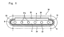
- Fig. 1 is a transverse sectional view of a fuel cell provided with an electrode support of the present invention, wherein the fuel cell generally designated at 30 is of the shape of a hollow flat plate and has an electrode support 31 which is flat in cross section and is of the shape of a slender plate as generally viewed.
- a plurality of fuel gas passages 31a are penetrating through in the electrode support 31 in the lengthwise direction maintaining a suitable gap, and the fuel cell 30 has a structure in which various members are provided on the electrode support 31.
- a plurality of the fuel cells 30 are connected in series by a collector member 40 to form cell stacks as shown in Fig. 2 .
- the cell stacks are contained in a predetermined container so as to be used as a fuel cell assembly.
- the electrode support 31 comprises a flat portion A and arcuate portions B at both ends of the flat portion A. Both surfaces of the flat portion A are formed nearly in parallel with each other, and a fuel electrode layer 32 is so provided as to cover the surfaces on one side of the flat portion A and of arcuate portions B on both sides thereof. Further, a dense electrolyte layer 33 is laminated so as to cover the fuel electrode layer 32, and an oxygen electrode layer 34 is laminated on the electrolyte layer 33 on one surface of the flat portion A so as to be opposed to the fuel electrode layer 32.
- an interconnector 35 is formed on the other surface of the flat portion A where neither the fuel electrode layer 32 nor the solid electrode layer 33 is laminated.
- the fuel electrode layer 32 and the electrolyte layer 33 are extending up to both sides of the interconnector 35, so that the surface of the electrode support 31 will not be exposed to the outer side.
- a portion of the fuel electrode layer 32 facing the oxygen electrode layer 34 works as a fuel electrode to generate electricity. That is, an oxygen-containing gas such as the air flows through along the outer side of the oxygen electrode layer 34, and a fuel gas (hydrogen) flows through the gas passages 31a in the electrode support 31.
- an oxygen-containing gas such as the air flows through along the outer side of the oxygen electrode layer 34
- a fuel gas hydrogen
- the electrode reaction represented by the following formula (1) takes place in the oxygen electrode layer 34 while the electrode reaction of the following formula (2) takes place in the fuel electrode layer 32 that works as the fuel electrode to generate electricity.
- Oxygen electrode 1/2O 2 + 2e - ⁇ O 2- (solid electrolyte) (1)
- the generated electric current is collected through the interconnector 35 attached to the electrode support 31. That is, a plurality of the fuel cells 30 of the above structure are connected in series by the collector member 40 to form cell stacks shown in Fig. 2 .
- the cell stacks are contained in the container so as to be used as a fuel cell assembly. By flowing the fuel gas (hydrogen) and the oxygen-containing gas into predetermined portions, the fuel cell assembly works as a cell.
- the electrode support 31 In the fuel cell 30 having the above structure, the electrode support 31 must be gas-permeable to permit the fuel gas to permeate through up to the fuel electrode layer 32, must be electrically conducting to collect electricity through the interconnector 35, and must, further, be resistant against developing cracks or exfoliation caused by a difference in the thermal expansion at the time of fabricating the fuel cell 30 by co-firing that will be described later.
- the electrode support 31 is made of an electrically conducting porous material and contains a phase (Ni phase) of metal nickel (Ni) or an oxide (NiO) thereof and an inorganic skeletal material phase that forms a basic skeleton.
- the Ni phase is for imparting electrically conducting property to the electrode support 31, and even when the Ni phase is formed by the nickel oxide (NiO) or the nickel oxide forms the Ni phase in the oxidizing atmosphere, a favorable electric conduction is exhibited at the time of generating electricity by reason that in the reducing atmosphere, the metal Ni forms the Ni phase. Further, the Ni phase also works as a reforming catalyst. Therefore, even in case a natural gas (CH 4 ) remains in the fuel gas (hydrogen), the Ni phase works to reform the natural gas into hydrogen making it possible to effectively utilize the fuel. Furthermore, the fuel electrode layer 32 that will be described later, usually, contains Ni. Upon containing the Ni phase in the electrode support 31, diffusion of elements can be effectively avoided between the electrode support 31 and the fuel electrode layer 32 at the time of firing or generating electricity.
- NiO nickel oxide
- the Ni phase also works as a reforming catalyst. Therefore, even in case a natural gas (CH 4 ) remains in the fuel gas (hydrogen), the Ni phase works to reform the natural gas into hydrogen making it possible to
- the inorganic skeletal material phase is formed of an inorganic oxide which is stable against the oxidizing atmosphere or the reducing atmosphere, forms a basic skeleton of the electrode support 31 and imparts a predetermined strength thereto.
- an oxide of a rare earth element is preferably used in order to bring, particularly, the coefficient of thermal expansion of the electrode support 31 close to that of the electrolyte layer 33 and to prevent diffusion of elements into the electrolyte layer 33.
- Y 2 O 3 As the oxides of rare earth elements, there can be exemplified Y 2 O 3 , Lu 2 O 3 , Yb 2 O 3 , Tm 2 O 3 , Er 2 O 3 , Ho 2 O 3 , DY 2 O 3 , Gd 2 O 3 , Sm 2 O 3 , and Pr 2 O 3 . Among them, however, Y 2 O 3 is preferred since it is particularly inexpensive.
- the electrode support 31 must have a fuel gas permeability and, usually, has an open porosity of not smaller than 30% and, particularly, in a range of 35 to 50% and an electric conductivity of not smaller than 300 S/cm and, particularly, not smaller than 440 S/cm.
- the electrode support 31 has a flat portion A of a length of, usually, 15 to 35 mm and an arculate portion B of a length (length of arc) of about 3 to 8 mm. It is further desired that the electrode support 31 has a thickness (distance between both surfaces of the flat portion A) of about 2.5 to 5 mm.
- the electrode support 31 of the present invention has various properties as described above, and it is particularly important that the oxidation/reduction expansion-suppressing metal M of at least one selected from the group consisting of Fe and Co is solidly dissolved in the Ni phase or is biasedly distributed on the grain boundaries between the Ni phase and the inorganic skeletal material phase.
- the biased distribution may be in the form of a reaction product with Ni or the organic skeletal material, or may be in an enriched form on the grain boundary.
- the electrode support 31 when the electrode support 31 is formed of a porous material comprising the Ni phase and the inorganic skeletal phase as described above, the volume of the electrode support 31 expands due to the reduction/oxidation cycles accompanying the generation of electricity and stop of generation giving rise to the occurrence of cracks in the electrolyte layer 33 and exfoliation of the fuel electrode layer 32 spoiling reliability of the fuel cells over the long run.
- the above oxidation/reduction expansion-suppressing metal M present in the Ni phase or on the grain boundaries between the Ni phase and the inorganic skeletal material phase Upon making the above oxidation/reduction expansion-suppressing metal M present in the Ni phase or on the grain boundaries between the Ni phase and the inorganic skeletal material phase, however, it is allowed to effectively prevent the expansion of volume due to the reduction/oxidation cycles, that causes various inconveniences.
- Fe exhibits reactivity to Ni and the inorganic skeletal material, and forms reaction products with Ni or inorganic skeletal material through the firing in a process for producing the electrode support.
- NiFe 2 O 4 as the reaction products of Fe and Ni
- FeYO 3 as the reaction products of Fe and a rear earth element oxide (Y 2 O 3 ).
- the reaction product of the above metal M and Ni or inorganic skeletal material chiefly precipitates on the grain boundaries between the Ni phase and the inorganic skeletal material phase, and the reaction product that has precipitated on the grain boundaries improves the wettability between the Ni phase and the inorganic skeletal material phase.
- the wettability between the Ni phase and the inorganic skeletal material phase is improved even by the metal M that is biasedly distributed on the grain boundaries in an enriched form in addition to the precipitation of the reaction product as will become understood from Experiment 2 appearing later.
- the inorganic skeletal material phase follows the contraction of the Ni phase due to the reduction, whereby the expansion of the Ni phase due to the oxidation is offset by the contraction due to the reduction, effectively avoiding the expansion of the electrode support 31 due to the reduction/oxidation cycles.
- the Ni oxide grows at a very increased rate as descried earlier. That is, in the oxidizing atmosphere of when the generation is discontinued, the Ni oxide grows into the interior of pores in the electrode support (porous material) 31, and the surrounding inorganic skeletal material phase is pulled inward by the Ni phase that grows due to the oxidation. As a result, the expansion due to the oxidation is very small and, often, contraction takes place. Therefore, the expansion due to the reduction/oxidation cycles can be effectively decreased even by suppressing the expansion due to the oxidation by having the metal M solidly dissolved therein as described above.
- the expansion due to the reduction/oxidation cycles can be decreased most effectively when a rare earth oxide and, particularly, Y 2 O 3 is used as the inorganic skeletal material and when the oxidation/reduction expansion-suppressing metal M is Fe or Co.
- the electrode support 31 may contain components in addition to Ni (or NiO), inorganic skeletal material and the oxidation/reduction expansion-suppressing metals M so far as the above-mentioned properties are not spoiled.
- the electrode support 31 may expand at the time of initial reduction (usually called reduction expansion). Though the reason has not been clarified yet, it is presumed that this stems from the precipitation of Ni as NiO is reduced. It has been experimentally confirmed that the reduction expansion can be effectively suppressed by having Mg and, particularly, MgO solidly dissolved in the Ni phase.
- the amount of Mg is desirably in a range of 0.1 to 20 mol% per the total amount thereof with Ni (Mg + Ni).
- the fuel electrode layer 32 triggers the electrode reaction of the formula (2) described above, and is made of a known porous and electrically conducting cermet.
- the fuel electrode layer 32 is formed of ZrO 2 in which a rare earth element is solidly dissolved, and Ni and/or NiO.
- ZrO 2 stabilized zirconia
- the content of the stabilized zirconia in the fuel electrode layer 32 is in a range of 35 to 65% by volume and that the content of Ni or NiO is 65 to 35% by volume. It is further desired that the fuel electrode layer 32 has an open porosity of not smaller than 15% and, particularly, in a range of 20 to 40%, and has a thickness of 1 to 30 ⁇ m. If the thickness of the fuel electrode layer 32 is too small, its performance may drop. If the thickness of the fuel electrode layer 32 is too large, on the other hand, exfoliation may occur due to a difference in the thermal expansion between the electrolyte layer 33 and the fuel electrode layer 32.
- the fuel electrode layer 32 is extending up to both sides of the interconnector 35.
- the fuel electrode may be formed so as to be present at a position facing the oxygen electrode 34.
- the fuel electrode layer 32 may be formed on only the flat portion A on, for example, the side where the oxygen electrode 34 is provided.
- the fuel electrode layer 32 may be formed over the whole circumference of the electrode support 31.
- it is desired that the electrolyte layer 33 as a whole is formed on the fuel electrode layer 32 in order to enhance the junction strength between the electrolyte layer 33 and the support 31.
- the electrolyte layer 33 formed on the fuel electrode layer 32 is made of dense ceramics called ZrO 2 (stabilized zirconia) in which a rare earth element is solidly dissolved, usually, in an amount of 3 to 15 mol%.
- a rare earth element there can be exemplified Sc, Y, La, Ce, Pr, Nd, Pm, Sm, Eu, Gd, Tb, Dy, Ho, Er, Tm, Yb and Lu.
- Y and Yb are desired since they are inexpensive.
- the stabilized zirconia ceramics forming the electrolyte layer 33 has a relative density (based on the Archimedes' method) of not smaller than 93% and, particularly, not smaller than 95% and has a thickness of 10 to 100 ⁇ m.
- the electrolyte layer 33 may be constituted by a perovskite composition of the type of lanthanum gallate in addition to being constituted by the stabilized zirconia.
- the oxygen electrode layer 34 is made of electrically conducting ceramics comprising a perovskite oxide of the so-called ABO 3 type.
- the perovskite oxide there can be preferably used a perovskite oxide of a transition metal and, particularly, at least one of an LaMnO 3 oxide, an LaFeO 3 oxide or an LaCoO 3 oxide having La on the A-site.
- the LaFeO 3 oxide is particularly desired from the standpoint of a high electrically conducting property at an operation temperature of about 600 to about 1000°C.
- the perovskite oxide may contain Sr in addition to La in the A-site, or may contain Co and Mn in addition to Fe in the B-site.
- the oxygen electrode layer 34 must have gas permeability. It is, therefore, desired that the electrically conducting ceramics (perovskite oxide) forming the oxygen electrode 34 has an open porosity of not smaller than 20% and, particularly, in a range of 30 to 50%.
- the oxygen electrode layer 34 has a thickness of 30 to 100 ⁇ m from the standpoint of collecting electricity.
- the interconnector 35 provided on the electrode support 31 comprises the electrically conducting ceramics which, however, comes in contact with the fuel gas (hydrogen) and the oxygen-containing gas. Therefore, the electrically conducting ceramics must have resistance against the reduction and resistance against the oxidation. As the electrically conducting ceramics, therefore, a peroviskite oxide (LaCrO 3 oxide) of the type of lanthanum chromite is usually used. In order to prevent the leakage of the fuel gas flowing inside the electrode support 31 and of the oxygen-containing gas flowing on the outer side of the electrode support 31, further, the electrically conducting ceramics must be dense and must, desirably, have a relative density of not smaller than 93% and, particularly, not smaller than 95%.
- the interconnector 35 has a thickness of 10 to 200 ⁇ m. If the thickness is smaller than the above range, gases tend to leak. If the thickness is larger than the above range, on the other hand, the electric resistance increases and the function for collecting electricity may decrease with a drop in the potential.
- the dense electrolyte layer 33 is closely adhered to both sides of the interconnector 35 to prevent the leakage of gases.
- a junction layer (not shown) comprising, for example, Y 2 O 3 may be provided between the electrolyte layer 33 and both side surfaces of the interconnector 35.
- the two Upon connecting the collector member 40 to the interconnector 35 via the P-type semiconductor layer 39, however, the two come into ohmic contact with each other, whereby the potential drops less effectively averting a drop in the electricity-collecting performance. For instance, an electric current from the oxygen electrode layer 34 of one fuel cell 30 can be efficiently conducted to the electrode support 31 of another fuel cell 30.
- the P-type semiconductor there can be exemplified a perovskite oxide of a transition metal.
- the P-type semiconductor having an electron conductivity larger than that of the LaCrO 3 oxide that constitutes the interconnector 35 there can be used P-type semiconductor ceramics comprising at least any one of an LaMnO 3 oxide, an LaFeO 3 oxide or LaCoO 3 oxide containing Mn, Fe or Co in the B-site. It is desired that the P-type semiconductor layer 39 has a thickness, usually, in a range of 30 to 100 ⁇ m.
- the interconnector 35 can also be directly provided on the flat portion A of the electrode support 31 on the side on where the electrolyte layer 33 is not provided.
- the fuel electrode layer 32 may be provided, and the interconnector 35 may be provided on the fuel electrode layer 32. That is, the fuel electrode layer 32 is provided over the whole circumference of the electrode support 31, and the interconnector 35 is provided on the fuel electrode layer 32.
- the electrode support 31 having the above-mentioned structure and the fuel cell equipped with the above electrode support 31 are produced as described below.
- a powder of Ni or of an oxide thereof, a powder of an inorganic skeletal material such as Y 2 O 3 and a powder of a compound containing the above-mentioned metal M for suppressing the oxidation/reduction expansion are mixed at a predetermined ratio, and to which are further mixed an organic binder such as an acrylic resin or a polyvinyl alcohol and a solvent such as an isopropyl alcohol or water to prepare a slurry thereof.
- the slurry is then extrusion-molded into a molded body for forming an electrode support and is dried (the electrode support 31 is obtained by firing the molded body for forming the electrode support).
- the compound which includes the oxidation/reduction expansion-suppressing metals M there can be used any compound provided it solidly dissolves in the Ni phase or forms a reaction product that precipitates on the grain boundaries.
- the metal M is used as an oxide (e.g., Fe 2 O 3 , Co 3 O 4 , etc.).
- the metal M may be used in the form of an alloy with Ni when the metal M is to be solidly dissolved in the Ni phase.
- the materials for forming the fuel electrode layer Ni or NiO powder and a powder of stabilized zirconia
- the organic binder and the solvent are mixed together to prepare a slurry and from which a sheet for forming the fuel electrode layer is formed.
- a coating for forming the fuel electrode layer may be formed by applying a paste that is obtained by dispersing the material for forming the fuel electrode in a solvent, onto a predetermined position of the molded body for forming the electrode support.
- the electrolyte powder such as the stabilized zirconia powder, the organic binder and the solvent are mixed together to prepare a slurry and from which a sheet is obtained for forming the electrolyte layer.
- the thus obtained molded body for forming the electrode support, the sheet for forming the fuel electrode and the sheet for forming the electrolyte are laminated so as to form a layer structure shown in, for example, Fig. 1 , are dried and, as required, are calcined at a temperature of about 1000°C.
- the sheet for forming the electrolyte only may be laminated on the molded body for forming the electrode support.
- the interconnector material e.g., LaCrO 3 oxide powder
- the organic binder and the solvent are mixed together to prepare a slurry thereof and from which a sheet for the interconnector is prepared.
- the sheet for the interconnector is, further, laminated on a predetermined position of the laminate obtained above to thereby prepare a laminate for firing.
- the laminate for firing is subjected to the treatment for removing the binder, and is co-fired in an oxygen-containing atmosphere at 1300 to 1600°C.
- a paste containing a material for forming the oxygen electrode (e.g., LaFeO 3 oxide powder) and a solvent, and, as required, a paste containing a material for forming the P-type semiconductor layer (e.g., LaFeO 3 oxide powder) and a solvent, are applied by dipping or the like method onto a predetermined position of the obtained sintered product, and are baked at 1000 to 1300°C to produce a fuel cell 30 equipped with the electrode support 31 of the structure shown in Fig. 1 .
- Ni When metal nickel is used for forming the electrode support 31 and the fuel electrode layer 32, Ni is oxidized into NiO due to the firing in the oxygen-containing atmosphere, which, however, can be returned back to Ni through the reduction treatment (or by the exposure to the reducing atmosphere at the time of generating electricity).
- the fuel cell 30 equipped with the electrode support 31 produced as described above is capable of effectively suppressing the expansion of volume of the electrode support 31 due to the reduction/oxidation cycles that accompany the generation of electricity (operation of the fuel cells 30) and stop of generation. It is, therefore, made possible to effectively prevent inconveniences such as occurrence of cracks in the electrolyte layer 33 due to the expansion or occurrence of exfoliation of the electrode support 31 and, therefore, to maintain reliability over extended periods of time.
- the cell stack is constituted by a set of a plurality of fuel cells 30 described above, by interposing the collector member 40 made of a metal felt and/or a metal plate between one fuel cell 30 and another fuel cell 30 neighboring each other up and down, and connecting the two in series with each other. That is, the electrode support 31 of the one fuel cell 30 is electrically connected to the oxygen electrode 34 of the other fuel cell 30 via the interconnector 35, P-type semiconductor layer 39 and collector member 40. As shown in Fig. 2 , further, the cell stacks are arranged side by side, and the neighboring cell stacks are connected in series with each other by the conductor members 42.
- the fuel cell assembly of the above structure contains the cell stacks of Fig. 2 in a container.
- the container is provided with an introduction pipe for introducing the fuel gas such as hydrogen from the external unit into the fuel cells 30, and an introduction pipe for introducing the oxygen-containing gas such as the air into space on the outer side of the fuel cells 30.
- a predetermined temperature e.g. 600 to 900°C
- the fuel cells Upon being heated at a predetermined temperature (e.g., 600 to 900°C), the fuel cells generate electricity, and the fuel gas and the oxygen-containing gas after used are discharged out of the container.
- the present invention can be varied in a variety of ways without departing from the gist of the invention.
- the electrode support 31 may be formed in a cylindrical shape, or the fuel cell 30 equipped with the electrode support 31 may include an intermediate layer having a suitable electrically conducting property formed between the oxygen electrode layer 34 and the electrolyte layer 33.
- the above embodiment has described the case where the fuel electrode layer 32 was formed on the electrode support 31.
- the electrode support 31 itself may be imparted with a function of the fuel electrode, and the electrolyte layer and the oxygen electrode layer may be formed on the electrode support which works as the fuel electrode.
- NiO powder having an average particle size of 0.5 ⁇ m and a Y 2 O 3 powder (having an average particle size of 0.6 to 0.9 ⁇ m) were mixed together in a manner that the amount of NiO after fired was 40% by volume calculated as Ni and the amount of Y 2 O 3 was 60% by volume.
- an Mn 2 O 3 powder (average particle size of 0.7 ⁇ m) was externally added in amounts as shown in Table 1 per 100 parts by mass of the above mixed powder, and mixed.
- Table 1 also shows the amounts (mol%) of Mn relative to the total amounts of Ni and Mn.
- a slurry was prepared by mixing the above mixed powder, a pore-imparting agent (fibrous cellulose), an organic binder (polyvinyl alcohol) and water (solvent) together, extrusion-molded into a rectangular parallelopiped shape which was, then, dried, subjected to the treatment for removing the binder, and was fired in the open air at 1500°C to prepare electrode supports (samples Nos. 1 to 4) .
- the sample No. 1 did not at all contain the Mn 2 O 3 powder.
- the electrode supports were oxidized in an oxidizing atmosphere of 850°C for 16 hours and were, thereafter, found for their coefficients of linear expansion in the same manner as described above. Similarly, further, the reduction/oxidation cycles were repeated three times to find the coefficients of linear expansion when reduced and oxidized up to three times, respectively. The results were as shown in Fig. 3 and in Table 1.
- the electrode supports machined as described above were measured for their electric conductivities by a 4-terminal method in a reducing atmosphere (850°C) under an oxygen partial pressure of about 10 -19 Pa. The results were as shown in Table 1.
- Table 1 Sample No. Mn 2 O 3 mass pts Coefficient of linear expansion (%) Conductivity S/cm 1st reduction 1st oxidation 2nd reduction 2nd oxidation 3rd reduction 3rd oxidation *1 0.0 0.06 0.22 0.16 0.30 0.21 0.43 643 *2 1.0(1.5) 0.07 0.02 0.08 -0.01 0.07 -0.04 633 *3 1.5(2.3) 0.04 0.09 0.11 0.11 0.11 0.11 624 *4 2.0(3.0) 0.08 0.16 0.15 0.20 0.18 0.19 616 Samples marked with * lie outside the scope of the invention. Coefficients of linear expansion represent the expansion when the sign is plus and the contraction when the sign is minus. In the column of Mn 2 O 3 amounts, values in parentheses are in mol%
- Mn 2 O 3 powder helps suppress the expansion due to the reduction/oxidation cycles. Further, if the amount of Mn 2 O 3 is small, the expansion becomes minus (contraction) and if the amount is large, the expansion increases. Further, as the amount of Mn 2 O 3 increases, the electric conductivity of the support slightly decreases but is still large enough.
- the amount of Mn is desirably in a range of 1 to 3 mol% per the total amount thereof with Ni (Mn + Ni).
- Figs. 4 to 7 illustrate the results of TEM analysis of the electrode support of the sample No. 3 produced above.
- the obtained electrode supports were measured for their coefficients of linear expansion after the reduction/oxidation cycles of three times in the same manner as in Experiment 1, and the results were as shown in Table 2 and in Fig. 8 . Further, the electric conductivities were measured in the reducing atmosphere like in Experiment 1 to obtain the results as shown in Table 2.
- the amount of Fe is desirably in a range of 0.04 to 3 mol% per the total amount thereof with Ni (Fe + Ni).
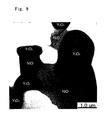
- Figs. 9 and 10 illustrate the results of transmission electron microscope (TEM) analysis of the electrode supports. It will be learned from the results that no reaction product of Fe is precipitating on the grain boundaries of Ni/Y 2 O 3 but Fe is biasedly distributed being solidly dissolved in the Ni phase. It is considered that despite of biasedly distributed on the grain boundaries, Fe works to suppress the change in the shape of Ni in the reduction of the next time and suppress the expansion of the electrode support caused by the subsequent reduction/oxidation cycles.
- TEM transmission electron microscope
- Co must be contained in an amount larger than that of Fe or Mn, and works to suppress the expansion of the support due to the reduction/oxidation cycles like the cases of Fe and Mn. It is desired that the amount of Co is in a range of 5 to 30 mol% per the total amount thereof with Ni (Co + Ni).
- sample powders (samples Nos. 5 to 9) used in Experiment 2 were extrusion-molded in the same manner as in Experiment 2 to form the flat molded bodies for forming electrode supports, which were, thereafter, dried.
- a ZrO 2 (YSZ) powder containing 8 mol% of Y 2 O 3 , an NiO powder, an organic binder (acrylic resin) and a solvent (toluene) were mixed together to prepare a slurry and from which a sheet for forming a fuel electrode layer was prepared.
- a sheet for forming a fuel electrode layer was prepared.
- the sheet for forming the fuel electrode layer and the sheet for forming the electrolyte layer were laminated.
- the laminated sheets were wrapped around the molded body for forming the electrode support prepared above in a manner that one flat surface of the molded body was exposed (see Fig. 1 ), and were dried.
- a slurry was prepared by mixing an LaCrO 3 oxide powder having an average particle size of 2 ⁇ m, an organic binder (acrylic resin) and a solvent (toluene), and a sheet for forming the interconnector was prepared by using the slurry.
- the sheet for the interconnector was laminated on the exposed flat portion of the molded body for forming the electrode support to thereby prepare a sheet for sintering comprising the molded body for forming the electrode support, sheet for forming the fuel electrode layer, sheet for forming the electrolyte layer and sheet for forming the interconnector.
- the sheet for sintering was subjected to the treatment for removing the binder and was co-fired in the open air at 1500°C to obtain a sintered body.
- the obtained sintered body was immersed in a paste comprising an La 0.6 Sr 0.4 Co 0.2 Fe 0.9 O 3 powder (oxygen electrode material) having an average particle size of 2 ⁇ m and a solvent (normal paraffin) so as to form a coating for forming the oxygen electrode on the surface of the electrolyte layer formed on the sintered body.
- the above paste was applied onto the outer surface of the interconnector to form a coating for forming the P-type semiconductor, followed by baking at 1150°C to thereby fabricate fuel cells of the structure shown in Fig. 1 (samples Nos. 13 to 17).
- the fabricated fuel cells possessed the flat portion A of the electrode support of a length of 26 mm, the arcuate portions B of a length of 3.5 mm and a thickness of 2.8 mm, the fuel electrode layer of a thickness of 10 ⁇ m, the electrolyte layer of a thickness of 40 ⁇ m, the oxygen electrode layer of a thickness of 50 ⁇ m, the interconnector of a thickness of 50 ⁇ m and the P-type semiconductor layer of a thickness of 50 ⁇ m.
- the electrolyte layer of the obtained fuel cell was analyzed for its cross section by using Electron Probe Micro-analyzer (EPMA) to confirm the elements diffused from the electrode support. Further, the hydrogen gas was flown into the gas passages in the electrode support and the air was flown along the outer side of the fuel cell (outer surface of the oxygen electrode) to generate electricity at 850°C for 100 hours. Thereafter, the supply of hydrogen gas was discontinued and the fuel cell was allowed to cool naturally (electrode support was oxidized).
- EPMA Electron Probe Micro-analyzer
- each fuel cell was measured for its generating ability after operated at 850°C for 100 hours (generation of the first time) to find the results as shown in Table 4.
- Table 4 Sample No. Electrode support (sample) No. Diffusion into solid electrolyte Cracks Generating performance W/cm 2 1st reduction 1st oxidation 2nd reduction 2nd oxidation 3rd reduction 3rd oxidation *13 5 - no yes yes yes yes 0.20 14 6 no no no no no no no no 0.41 15 7 no no no no no no 0.41 16 8 no no no no no no 0.43 17 9 no no no no no no no no 0.44 Samples marked with * lie outside the scope of the invention.
Landscapes
- Engineering & Computer Science (AREA)
- Manufacturing & Machinery (AREA)
- Chemical & Material Sciences (AREA)
- Chemical Kinetics & Catalysis (AREA)
- Electrochemistry (AREA)
- General Chemical & Material Sciences (AREA)
- Life Sciences & Earth Sciences (AREA)
- Sustainable Development (AREA)
- Sustainable Energy (AREA)
- Fuel Cell (AREA)
- Inert Electrodes (AREA)
Description
- The present invention relates to an electrode support for fuel cells. More specifically, this invention relates to an electrode support which is used in a solid oxide fuel cell having an electrode structure including a fuel electrode and an oxygen electrode with the electrolyte layer held therebetween, said electrode support supporting the electrode structure or a laminate of the electrolyte layer and the oxygen electrode layer.
- In recent years, various kinds of fuel cell assembles have been proposed as energy sources of the next generation containing a stack of fuel cells in a container.
-
Fig. 11 shows a stack (cell stack) of conventional solid oxide fuel cells. The cell stack has a plurality offuel cells 1 which are arranged in alignment, acollector member 5 of a metal felt being interposed between the one fuel cell la and anotherfuel cell 1b which are neighboring each other, and afuel electrode 7 of the one fuel cell 1a being electrically connected to an oxygen electrode (air electrode) 11 of theother fuel cell 1b. - The fuel cell 1 (1a, 1b) comprises an
electrolyte 9 and theoxygen electrode 11 of electrically conducting ceramics formed in this order on the outer peripheral surface of thefuel electrode 7 of a cylindrical cermet (the inner space is a fuel gas passage), and has aninterconnector 13 provided on the surface of thefuel electrode 7 which is covered with neither theelectrolyte 9 nor theoxygen electrode 11. As is obvious fromFig. 11 , theinterconnector 13 is electrically connected to thefuel electrode 7 but so will not to be connected to theoxygen electrode 11. - The
interconnector 13 is formed by using electrically conducting ceramics that is little subject to be degenerated with the fuel gas or the oxygen-containing gas such as the air. Here, the electrically conducting ceramics must be so dense as to reliably isolate the fuel gas flowing inside thefuel electrode 7 from the oxygen-containing gas flowing on the outer side of theoxygen electrode 11 - Further, the
collector member 5 provided between the neighboringfuel cells 1a and 1b is electrically connected to thefuel electrode 7 of the one fuel cell la through theinterconnector 13 and is further connected to theoxygen electrode 11 of theother fuel cell 1b. Therefore, the neighboring fuel cells are connected in series. - By containing the cell stack having the above-mentioned structure in the container, the fuel cell is used in the form of an assembly. For example, the fuel gas (hydrogen) flows inside the
fuel electrode 7 and the air (oxygen) flows along theoxygen electrode 11, and electricity is generated at about 750 to about 1000°C. - In the above fuel cell, in general, the
fuel electrode 7 comprises Ni and Y2O3-containing ZrO2 called stabilized zirconia (YSZ), theelectrolyte 9 comprises ZrO2 (YSZ) containing Y2O3, and theoxygen electrode 11 comprises a perovskite composite oxide of the type of lanthanum manganate. - As the method of producing the above fuel cells, there has been known a so-called co-firing method which fires the
fuel electrode 7 and theelectrolyte 9 simultaneously. The co-firing method is a very simple process having a decreased number of production steps, and is advantageous for improving the yield of cell production and for decreasing the cost. - Here, the Y2O3-containing ZrO2 forming the
electrolyte 9 has a coefficient of thermal expansion of about 10.8 x 10⁻⁶/°C whereas thefuel electrode 7 supporting theelectrolyte 9 contains Ni having a coefficient of thermal expansion of 16.3 x 20-6/°C which is very larger than that of YSZ. In conducting the co-firing as described above, therefore, a difference in the thermal expansion becomes great between theelectrolyte 9 and thefuel electrode 7 supporting the electrolyte arousing such problems as the occurrence of cracks in thefuel electrode 7 and exfoliation of theelectrolyte 9. - As a fuel cell solving the above problems, there has been known a fuel cell obtained by forming a fuel electrode, an electrolyte and an oxygen electrode layer on a support board of a porous material which contains Ni and a rare earth oxide (Y2O3 or Yb2O3) having a coefficient of thermal expansion lower than that of ZrO2 (see
JP 2004-146334 A - According to the above fuel cell, the coefficient of thermal expansion of the support board can be brought close to the coefficient of thermal expansion of the electrolyte. At the time of co-firing, therefore, it is made possible to suppress the occurrence of cracks in the fuel electrode and exfoliation of the electrolyte from the fuel electrode. Japanese patent application
JP 2004-179071 A - Concerning the inconvenience stemming from the thermal expansion as described above, various proposals have been made as taught in the
patent document 1. The fuel cell, however, further involves a problem of expansion due to the oxidation/reduction cycles in addition to the thermal expansion. - That is, at the time of generating electricity, the interior of the fuel cell is exposed to the reducing atmosphere due to the supply of the fuel gas (hydrogen). When the generation is halted, however, no fuel gas is fed into the cell which is under a high-temperature condition from the standpoint of safety and economy. Therefore, the interior of the cell changes from the reducing atmosphere into the oxidizing atmosphere. In general, however, in order to maintain a predetermined strength, the fuel cell uses an electrode support; i.e., an electrode structure is formed on the electrode support, and the electricity is collected through the electrode support. For example, in the cells of
Fig. 11 , thefuel electrode 7 is serving as an electrode support, and theelectrolyte 9 and theoxygen electrode 11 are formed on thefuel electrode 7 which is the electrode support. The above electrode support, usually, occupies a majority proportion of the cell volume. Even in the fuel cell in which a laminated layer structure of fuel electrode, electrolyte and oxygen electrode is formed on the electrode support, the electrode support occupies a majority proportion of the cell. Therefore, stability of the electrode support plays an important role in the varying atmosphere. - Here, the electrode support contains a metal for imparting electrically conducting property, and Ni is usually used as the metal. Ni has a function as a reforming catalyst for forming the fuel gas (hydrogen) from the natural gas and makes it possible to effectively utilize the fuel. Besides, Ni is also contained in the fuel electrode and is desired in forming the fuel electrode on the electrode support and in preventing inconvenience caused by the diffusion of elements between the fuel electrode and the electrode support under high-temperature conditions. However, the metal such as Ni undergoes the oxidation in an oxidizing atmosphere of when the generation of electricity is discontinued. Accompanying this, therefore, the volume of the electrode support expands. Further, the metal that is oxidized undergoes the reduction in a reducing atmosphere. Therefore, the electrode support that has expanded, then, contracts. Therefore, if the oxidizing atmosphere changes into the reducing atmosphere, it is theoretically considered that the electrode support resumes its initial volume. In practice, however, the volume does not return to the initial state but remains in a slightly expanded state. Upon repetitively changing the atmosphere (i.e., repeating the generation and stop of generation), therefore, the volume of the electrode support gradually increases. Due to the expansion of the electrode support, therefore, cracks occur in the electrolyte formed on the electrode support, electrolyte exfoliates, or the electrode support itself is cracked, which are the causes of destruction fatal to the cells. So far, however, almost no approach has been made concerning the mechanism of expansion of volume of the electrode support due to a change in the atmosphere or concerning the prevention of expansion of the volume of the electrode support.
- It is, therefore, an object of the present invention to provide an electrode support for fuel cells suppressing the expansion of volume even in an environment in which it is exposed to the reducing atmosphere and the oxidizing atmosphere alternately.
- Another object of the present invention is to provide a fuel cell which has the above electrode support and features improved reliability for extended periods of time.
- According to the present invention, there is provided a solid oxide fuel cell according to
claim 1. - In the electrode support of the fuel cell, it is desired that:
- (1) the inorganic skeletal material is an oxide of a rare earth element;
- (2) the inorganic skeletal material is Y2O3;
- (4) the oxidation/reduction expansion-suppressing metal M is Fe, and is precipitated in the form of NiFe2O4 or FeYO3 on the grain boundaries;
- (5) Fe is biasedly distributed on the grain boundaries; and
- (6) the oxidation/reduction expansion-suppressing metal M is Co, and is solidly dissolved in the Ni phase.
- According to the present invention, further, there is provided a solid oxide fuel cell having a structure in which a fuel electrode, an electrolyte and an oxygen electrode are laminated in this order on one surface of the electrode support.
- The invention further provides a cell stack obtained by electrically connecting a plurality of fuel cells in series, and a fuel cell assembly obtained by containing the cell stack in a container.
- The electrode support for fuel cells of the invention is made of a porous material having a Ni phase (Ni or NiO) and an inorganic skeletal material phase. In particular, an important feature resides in that the oxidation/reduction expansion-suppressing metal M described above is solidly dissolved in the Ni phase or is biasedly distributed on the grain boundaries between the Ni phase and the inorganic skeletal material phase. Presence of the above metal M effectively suppresses the volume expansion caused by the reduction/oxidation cycles (repetition of change in the atmosphere between the reducing atmosphere and the oxidizing atmosphere).
- That is, the Ni phase imparts the electrically conducting property and the function of the reforming catalyst to the electrode support while the inorganic skeletal material phase comprises an inorganic material which remains stable against the oxidizing atmosphere and the reducing atmosphere, and forms a basic skeleton of the support. When the support (porous member) having the Ni phase and the inorganic skeletal material phase is alternately exposed to the reducing atmosphere and the oxidizing atmosphere (reduction and oxidation are repeated), the reduction and oxidation are alternately repeated in the Ni phase. If oxidized, the volume expands by an amount Ni oxidized. If the oxide is reduced, therefore, it is theoretically considered that the volume contracts and the initial volume will be resumed. As described above, however, the initial volume is not really resumed even after the oxide is reduced, and the electrode support gradually expands as the reduction and oxidation are repeated. Though the mechanism of expansion of the support through the reduction/oxidation cycles has not been clarified yet, the present inventors presume it as described below.
- If the Ni phase expands due to the oxidation, the inorganic skeletal material phase present around the Ni phase is pushed outward and the electrode support expands. Next, if the Ni phase reduces being exposed to the reducing atmosphere, NiO turns into Ni and contracts. However, the inorganic skeletal material (e.g., oxide of rare earth element) constituting the electrode support remains stable against the oxidation and reduction and exhibits poor wettability to the metal nickel (or oxide thereof). Therefore, even if the inorganic skeletal material phase in a state of being expanded by oxidation comes into favorable contact with the Ni phase that is expanded, the Ni phase partly separates away from the inorganic skeletal material phase when it is contracted due to the reduction (the inorganic skeletal material phase does not follow the Ni phase that contracts). As a result, it is considered that the volume of the electrode support that has expanded due to oxidation does not return back to the initial volume despite it is contracted by reduction and, therefore, the volume becomes slightly greater than the volume of before being oxidized.
- According to the present invention, the expansion due to the reduction/oxidation cycles is suppressed by making present a particular metal M. The present inventors presume the mechanism of suppression as described below.
- First, among the metals M for suppressing the oxidation/reduction expansion described above, Fe is reactive for Ni and inorganic skeletal material (e.g., Y2O3), and the reaction product thereof precipitates on the grain boundaries between the Ni phase and the inorganic skeletal material phase during the firing in the process for producing the electrode support or, if it is not the reaction product, are biasedly distributed on the grain boundaries in an enriched form. As a result, it is considered that wettability improves between the Ni phase and the inorganic skeletal material phase, and the inorganic skeletal material phase follows the Ni phase when the Ni phase contracts by reduction. Consequently, expansion due to the oxidation is offset by contraction at the time of reduction effectively avoiding the expansion of the electrode support due to the reduction/oxidation cycles. Further, these metals M are polyvalent metals and solidly dissolve in the Ni phase if their amounts are very small working to conspicuously increase the growing rate of the Ni oxide. When exposed to the oxidizing atmosphere, therefore, the Ni oxide grows into the pores in the electrode support which is the porous material. This is because oxygen is easily fed in the pores. Thus, as the Ni oxide quickly grows into the pores, the surrounding inorganic skeletal material phase is pulled by the Ni phase. Accordingly, expansion by the oxidation is very small in the oxidizing atmosphere, and contraction is often observed depending upon the cases. Therefore, the expansion due to the reduction/oxidation cycles is also effectively decreased even by an increase in the rate of growth of the Ni oxide due to the metal M that solidly dissolves in the Ni phase.
- Further, among the oxidation/reduction expansion-suppressing metals M, Co entirely and solidly dissolves in the Ni phase and does not form a reaction product with the inorganic skeletal material. However, wettability is improved between the Ni phase in which Co is solidly dissolved and the inorganic skeletal material phase. As a result, in the same manner as described above, the inorganic skeletal material phase follows the Ni phase when the Ni phase contracts due to the reduction effectively avoiding the expansion of the electrode support caused by the reduction/oxidation cycles.
- According to the present invention, precipitation of the reaction product of Ni or the inorganic skeletal material with the metal M, biased distribution thereof on the grain boundaries, and presence of the metal M solidly dissolved in Ni, can be confirmed by the X-ray diffraction (XRD) of the powder or by the X-ray microanalysis (EPMA) and, particularly, by the limited visual field electron diffraction image analysis (SAED) or the X-ray analysis (EDS), or by the secondary ion mass analysis (SIMS).
- As described above, the electrode support of the present invention is suppressed from expanding despite of subjected to the reduction/oxidation cycles. As will become clear from Examples appearing later, the electrode support of the invention exhibits an absolute value of a coefficient of linear expansion of not larger than 0.2% after subjected to the reduction/oxidation cycles three times repetitively.
- The electrode support of the invention can be used for the fuel cells by forming thereon the fuel electrode layer, electrolyte and oxygen electrode layer successively, works to effectively suppress cracks in the fuel electrode and in the electrolyte as well as exfoliation even when the start and stop are repeated, and contributes to improving reliability in the long run when put to a practical use in the general household where start/stop are frequent.
-
-
Fig. 1 is a transverse sectional view of a fuel cell provided with an electrode support of the present invention; -
Fig. 2 is a transverse sectional view of cell stacks formed by using the fuel cells ofFig. 1 ; -
Fig. 3 is a graph showing coefficients of linear expansion of the electrode supports of samples Nos. 1 to 4 prepared inExperiment 1 after the reduction/oxidation cycle testing; -
Fig. 4 is an elemental mapping image of the electrode support (present invention) of sample No. 3 prepared inExperiment 1 measured by the TEM-EDS; -
Fig. 5 is a bright visual field image of the electrode support (present invention) of sample No. 3 prepared inExperiment 1 measured by the TEM; -
Fig. 6 is a diagram of elemental analysis spectra of the grain boundary phase of the electrode support (present invention) of sample No. 3 prepared inExperiment 1 measured by the TEM-EDS; -
Fig. 7 shows the results of the limited visual field electron diffraction image analysis of the grain boundary phase of the electrode support (present invention) of sample No. 3 prepared inExperiment 1 measured by the TEM; -
Fig. 8 is a graph showing coefficients of linear expansion of the electrode supports of samples Nos. 5 to 8 prepared inExperiment 2 after the reduction/oxidation cycle testing; -
Fig. 9 is a bright visual field image of the electrode support (present invention) of sample No. 7 prepared inExperiment 2 measured by the TEM; -
Fig. 10 is a diagram of the results of elemental analysis of the grain boundary portion of the electrode support (present invention) of sample No. 7 prepared inExperiment 2 measured by the TEM-EDS; and -
Fig. 11 is a transverse sectional view of cell stacks comprising conventional fuel cells. - The invention will now be described in detail with reference to the accompanying drawings.
-
Fig. 1 is a transverse sectional view of a fuel cell provided with an electrode support of the present invention, wherein the fuel cell generally designated at 30 is of the shape of a hollow flat plate and has anelectrode support 31 which is flat in cross section and is of the shape of a slender plate as generally viewed. A plurality offuel gas passages 31a are penetrating through in theelectrode support 31 in the lengthwise direction maintaining a suitable gap, and thefuel cell 30 has a structure in which various members are provided on theelectrode support 31. Usually, a plurality of thefuel cells 30 are connected in series by acollector member 40 to form cell stacks as shown inFig. 2 . The cell stacks are contained in a predetermined container so as to be used as a fuel cell assembly. - As will be understood from the shape shown in
Fig. 1 , theelectrode support 31 comprises a flat portion A and arcuate portions B at both ends of the flat portion A. Both surfaces of the flat portion A are formed nearly in parallel with each other, and afuel electrode layer 32 is so provided as to cover the surfaces on one side of the flat portion A and of arcuate portions B on both sides thereof. Further, adense electrolyte layer 33 is laminated so as to cover thefuel electrode layer 32, and anoxygen electrode layer 34 is laminated on theelectrolyte layer 33 on one surface of the flat portion A so as to be opposed to thefuel electrode layer 32. - Further, an
interconnector 35 is formed on the other surface of the flat portion A where neither thefuel electrode layer 32 nor thesolid electrode layer 33 is laminated. As will be clear fromFig. 1 , thefuel electrode layer 32 and theelectrolyte layer 33 are extending up to both sides of theinterconnector 35, so that the surface of theelectrode support 31 will not be exposed to the outer side. - In the fuel cell of the above structure, a portion of the
fuel electrode layer 32 facing theoxygen electrode layer 34 works as a fuel electrode to generate electricity. That is, an oxygen-containing gas such as the air flows through along the outer side of theoxygen electrode layer 34, and a fuel gas (hydrogen) flows through thegas passages 31a in theelectrode support 31. Upon being heated up to a predetermined working temperature, the electrode reaction represented by the following formula (1) takes place in theoxygen electrode layer 34 while the electrode reaction of the following formula (2) takes place in thefuel electrode layer 32 that works as the fuel electrode to generate electricity.
Oxygen electrode: 1/2O2 + 2e- → O2- (solid electrolyte) (1)
Fuel electrode: O2- (solid electrolyte) + H2 → H2O + 2e- (2)
- The generated electric current is collected through the
interconnector 35 attached to theelectrode support 31. That is, a plurality of thefuel cells 30 of the above structure are connected in series by thecollector member 40 to form cell stacks shown inFig. 2 . The cell stacks are contained in the container so as to be used as a fuel cell assembly. By flowing the fuel gas (hydrogen) and the oxygen-containing gas into predetermined portions, the fuel cell assembly works as a cell. - In the
fuel cell 30 having the above structure, theelectrode support 31 must be gas-permeable to permit the fuel gas to permeate through up to thefuel electrode layer 32, must be electrically conducting to collect electricity through theinterconnector 35, and must, further, be resistant against developing cracks or exfoliation caused by a difference in the thermal expansion at the time of fabricating thefuel cell 30 by co-firing that will be described later. In order to satisfy the above requirement, theelectrode support 31 is made of an electrically conducting porous material and contains a phase (Ni phase) of metal nickel (Ni) or an oxide (NiO) thereof and an inorganic skeletal material phase that forms a basic skeleton. - That is, the Ni phase is for imparting electrically conducting property to the
electrode support 31, and even when the Ni phase is formed by the nickel oxide (NiO) or the nickel oxide forms the Ni phase in the oxidizing atmosphere, a favorable electric conduction is exhibited at the time of generating electricity by reason that in the reducing atmosphere, the metal Ni forms the Ni phase. Further, the Ni phase also works as a reforming catalyst. Therefore, even in case a natural gas (CH4) remains in the fuel gas (hydrogen), the Ni phase works to reform the natural gas into hydrogen making it possible to effectively utilize the fuel. Furthermore, thefuel electrode layer 32 that will be described later, usually, contains Ni. Upon containing the Ni phase in theelectrode support 31, diffusion of elements can be effectively avoided between theelectrode support 31 and thefuel electrode layer 32 at the time of firing or generating electricity. - The inorganic skeletal material phase is formed of an inorganic oxide which is stable against the oxidizing atmosphere or the reducing atmosphere, forms a basic skeleton of the
electrode support 31 and imparts a predetermined strength thereto. As the inorganic oxide, an oxide of a rare earth element is preferably used in order to bring, particularly, the coefficient of thermal expansion of theelectrode support 31 close to that of theelectrolyte layer 33 and to prevent diffusion of elements into theelectrolyte layer 33. As the oxides of rare earth elements, there can be exemplified Y2O3, Lu2O3, Yb2O3, Tm2O3, Er2O3, Ho2O3, DY2O3, Gd2O3, Sm2O3, and Pr2O3. Among them, however, Y2O3 is preferred since it is particularly inexpensive. - The above Ni component and the inorganic skeletal material are contained in the
electrode support 31 at a volume ratio of Ni component:inorganic skeletal material = 35:65 to 65:35 calculated as oxides in order to maintain a favorable electric conduction and to accomplish a coefficient of thermal expansion close to that of the electrolyte material forming theelectrolyte layer 33. - The
electrode support 31 must have a fuel gas permeability and, usually, has an open porosity of not smaller than 30% and, particularly, in a range of 35 to 50% and an electric conductivity of not smaller than 300 S/cm and, particularly, not smaller than 440 S/cm. - It is desired that the
electrode support 31 has a flat portion A of a length of, usually, 15 to 35 mm and an arculate portion B of a length (length of arc) of about 3 to 8 mm. It is further desired that theelectrode support 31 has a thickness (distance between both surfaces of the flat portion A) of about 2.5 to 5 mm. - The
electrode support 31 of the present invention has various properties as described above, and it is particularly important that the oxidation/reduction expansion-suppressing metal M of at least one selected from the group consisting of Fe and Co is solidly dissolved in the Ni phase or is biasedly distributed on the grain boundaries between the Ni phase and the inorganic skeletal material phase. The biased distribution may be in the form of a reaction product with Ni or the organic skeletal material, or may be in an enriched form on the grain boundary. That is, when theelectrode support 31 is formed of a porous material comprising the Ni phase and the inorganic skeletal phase as described above, the volume of theelectrode support 31 expands due to the reduction/oxidation cycles accompanying the generation of electricity and stop of generation giving rise to the occurrence of cracks in theelectrolyte layer 33 and exfoliation of thefuel electrode layer 32 spoiling reliability of the fuel cells over the long run. Upon making the above oxidation/reduction expansion-suppressing metal M present in the Ni phase or on the grain boundaries between the Ni phase and the inorganic skeletal material phase, however, it is allowed to effectively prevent the expansion of volume due to the reduction/oxidation cycles, that causes various inconveniences. - That is, among the oxidation/reduction expansion-suppressing metals M, Fe exhibits reactivity to Ni and the inorganic skeletal material, and forms reaction products with Ni or inorganic skeletal material through the firing in a process for producing the electrode support. There can be exemplified NiFe2O4 as the reaction products of Fe and Ni; and FeYO3 as the reaction products of Fe and a rear earth element oxide (Y2O3). The reaction product of the above metal M and Ni or inorganic skeletal material chiefly precipitates on the grain boundaries between the Ni phase and the inorganic skeletal material phase, and the reaction product that has precipitated on the grain boundaries improves the wettability between the Ni phase and the inorganic skeletal material phase. Further, the wettability between the Ni phase and the inorganic skeletal material phase is improved even by the metal M that is biasedly distributed on the grain boundaries in an enriched form in addition to the precipitation of the reaction product as will become understood from
Experiment 2 appearing later. As a result, if the Ni phase contracts due to the reduction, the inorganic skeletal material phase follows the contraction of the Ni phase due to the reduction, whereby the expansion of the Ni phase due to the oxidation is offset by the contraction due to the reduction, effectively avoiding the expansion of theelectrode support 31 due to the reduction/oxidation cycles. - Further, when the polyvalent metal (the metal M) is solidly dissolved in the Ni phase, the Ni oxide grows at a very increased rate as descried earlier. That is, in the oxidizing atmosphere of when the generation is discontinued, the Ni oxide grows into the interior of pores in the electrode support (porous material) 31, and the surrounding inorganic skeletal material phase is pulled inward by the Ni phase that grows due to the oxidation. As a result, the expansion due to the oxidation is very small and, often, contraction takes place. Therefore, the expansion due to the reduction/oxidation cycles can be effectively decreased even by suppressing the expansion due to the oxidation by having the metal M solidly dissolved therein as described above.
- Among the oxidation/reduction expansion-suppressing metals M, Co entirely and solidly dissolves in the Ni phase; i.e., wettability is improved due to the solidly dissolved impurity effectively avoiding the expansion of the
electrode support 31 due to the reduction/oxidation cycles. - The above description has dealt with the case of using Y2O3 as the inorganic skeletal material, which, however, also holds even when the other rare earth element oxide is used as the inorganic skeletal material.
- In the present invention, the expansion due to the reduction/oxidation cycles can be decreased most effectively when a rare earth oxide and, particularly, Y2O3 is used as the inorganic skeletal material and when the oxidation/reduction expansion-suppressing metal M is Fe or Co.
- The
electrode support 31 may contain components in addition to Ni (or NiO), inorganic skeletal material and the oxidation/reduction expansion-suppressing metals M so far as the above-mentioned properties are not spoiled. - In a state where the wettability is enhanced between the Ni phase and the inorganic skeletal material phase, the
electrode support 31 may expand at the time of initial reduction (usually called reduction expansion). Though the reason has not been clarified yet, it is presumed that this stems from the precipitation of Ni as NiO is reduced. It has been experimentally confirmed that the reduction expansion can be effectively suppressed by having Mg and, particularly, MgO solidly dissolved in the Ni phase. The amount of Mg is desirably in a range of 0.1 to 20 mol% per the total amount thereof with Ni (Mg + Ni). - In the present invention, the
fuel electrode layer 32 triggers the electrode reaction of the formula (2) described above, and is made of a known porous and electrically conducting cermet. For example, thefuel electrode layer 32 is formed of ZrO2 in which a rare earth element is solidly dissolved, and Ni and/or NiO. As the ZrO2 (stabilized zirconia) in which the rare earth element is solidly dissolved, there can be used the one same as that used for forming theelectrolyte layer 33 that will be described later. - It is desired that the content of the stabilized zirconia in the
fuel electrode layer 32 is in a range of 35 to 65% by volume and that the content of Ni or NiO is 65 to 35% by volume. It is further desired that thefuel electrode layer 32 has an open porosity of not smaller than 15% and, particularly, in a range of 20 to 40%, and has a thickness of 1 to 30 µm. If the thickness of thefuel electrode layer 32 is too small, its performance may drop. If the thickness of thefuel electrode layer 32 is too large, on the other hand, exfoliation may occur due to a difference in the thermal expansion between theelectrolyte layer 33 and thefuel electrode layer 32. - In the example of
Fig. 1 , thefuel electrode layer 32 is extending up to both sides of theinterconnector 35. However, the fuel electrode may be formed so as to be present at a position facing theoxygen electrode 34. Namely, thefuel electrode layer 32 may be formed on only the flat portion A on, for example, the side where theoxygen electrode 34 is provided. Further, thefuel electrode layer 32 may be formed over the whole circumference of theelectrode support 31. In the present invention, it is desired that theelectrolyte layer 33 as a whole is formed on thefuel electrode layer 32 in order to enhance the junction strength between theelectrolyte layer 33 and thesupport 31. - The
electrolyte layer 33 formed on thefuel electrode layer 32 is made of dense ceramics called ZrO2 (stabilized zirconia) in which a rare earth element is solidly dissolved, usually, in an amount of 3 to 15 mol%. As the rare earth element, there can be exemplified Sc, Y, La, Ce, Pr, Nd, Pm, Sm, Eu, Gd, Tb, Dy, Ho, Er, Tm, Yb and Lu. Among them, however, Y and Yb are desired since they are inexpensive. - From the standpoint of preventing gas permeability, it is desired that the stabilized zirconia ceramics forming the
electrolyte layer 33 has a relative density (based on the Archimedes' method) of not smaller than 93% and, particularly, not smaller than 95% and has a thickness of 10 to 100 µm. Theelectrolyte layer 33 may be constituted by a perovskite composition of the type of lanthanum gallate in addition to being constituted by the stabilized zirconia. - The
oxygen electrode layer 34 is made of electrically conducting ceramics comprising a perovskite oxide of the so-called ABO3 type. As the perovskite oxide, there can be preferably used a perovskite oxide of a transition metal and, particularly, at least one of an LaMnO3 oxide, an LaFeO3 oxide or an LaCoO3 oxide having La on the A-site. Among them, the LaFeO3 oxide is particularly desired from the standpoint of a high electrically conducting property at an operation temperature of about 600 to about 1000°C. The perovskite oxide may contain Sr in addition to La in the A-site, or may contain Co and Mn in addition to Fe in the B-site. - The
oxygen electrode layer 34 must have gas permeability. It is, therefore, desired that the electrically conducting ceramics (perovskite oxide) forming theoxygen electrode 34 has an open porosity of not smaller than 20% and, particularly, in a range of 30 to 50%. - It is desired that the
oxygen electrode layer 34 has a thickness of 30 to 100 µm from the standpoint of collecting electricity. - At a position facing the
oxygen electrode layer 34, theinterconnector 35 provided on theelectrode support 31 comprises the electrically conducting ceramics which, however, comes in contact with the fuel gas (hydrogen) and the oxygen-containing gas. Therefore, the electrically conducting ceramics must have resistance against the reduction and resistance against the oxidation. As the electrically conducting ceramics, therefore, a peroviskite oxide (LaCrO3 oxide) of the type of lanthanum chromite is usually used. In order to prevent the leakage of the fuel gas flowing inside theelectrode support 31 and of the oxygen-containing gas flowing on the outer side of theelectrode support 31, further, the electrically conducting ceramics must be dense and must, desirably, have a relative density of not smaller than 93% and, particularly, not smaller than 95%. - From the standpoint of preventing the leakage of gases and electric resistance, further, it is desired that the
interconnector 35 has a thickness of 10 to 200 µm. If the thickness is smaller than the above range, gases tend to leak. If the thickness is larger than the above range, on the other hand, the electric resistance increases and the function for collecting electricity may decrease with a drop in the potential. - As is understood from
Fig. 1 , further, thedense electrolyte layer 33 is closely adhered to both sides of the interconnector 35 to prevent the leakage of gases. In order to improve the sealing, further, a junction layer (not shown) comprising, for example, Y2O3 may be provided between theelectrolyte layer 33 and both side surfaces of theinterconnector 35. - It is desired to provide a P-
type semiconductor layer 39 on the outer surface (upper surface) of theinterconnector 35. That is, in the cell stack assembled by stacking the fuel cells (seeFig. 2 ), an electrically conductingcollector member 40 is connected to theinterconnector 35. However, if thecollector member 40 is directly connected to theinterconnector 35, the potential drops greatly due to non-ohmic contact, and the electricity-collecting performance drops. - Upon connecting the
collector member 40 to theinterconnector 35 via the P-type semiconductor layer 39, however, the two come into ohmic contact with each other, whereby the potential drops less effectively averting a drop in the electricity-collecting performance. For instance, an electric current from theoxygen electrode layer 34 of onefuel cell 30 can be efficiently conducted to theelectrode support 31 of anotherfuel cell 30. As the P-type semiconductor, there can be exemplified a perovskite oxide of a transition metal. - Concretely, there can be used the P-type semiconductor having an electron conductivity larger than that of the LaCrO3 oxide that constitutes the
interconnector 35. For example, there can be used P-type semiconductor ceramics comprising at least any one of an LaMnO3 oxide, an LaFeO3 oxide or LaCoO3 oxide containing Mn, Fe or Co in the B-site. It is desired that the P-type semiconductor layer 39 has a thickness, usually, in a range of 30 to 100 µm. - The
interconnector 35 can also be directly provided on the flat portion A of theelectrode support 31 on the side on where theelectrolyte layer 33 is not provided. In this portion, too, thefuel electrode layer 32 may be provided, and theinterconnector 35 may be provided on thefuel electrode layer 32. That is, thefuel electrode layer 32 is provided over the whole circumference of theelectrode support 31, and theinterconnector 35 is provided on thefuel electrode layer 32. When theinterconnector 35 is provided on theelectrode support 31 via thefuel electrode layer 32, a drop of potential is suppressed on the interface between theelectrode support 31 and theinterconnector 35, which is advantageous. - The
electrode support 31 having the above-mentioned structure and the fuel cell equipped with theabove electrode support 31 are produced as described below. - First, a powder of Ni or of an oxide thereof, a powder of an inorganic skeletal material such as Y2O3 and a powder of a compound containing the above-mentioned metal M for suppressing the oxidation/reduction expansion, are mixed at a predetermined ratio, and to which are further mixed an organic binder such as an acrylic resin or a polyvinyl alcohol and a solvent such as an isopropyl alcohol or water to prepare a slurry thereof. The slurry is then extrusion-molded into a molded body for forming an electrode support and is dried (the
electrode support 31 is obtained by firing the molded body for forming the electrode support). - As the compound which includes the oxidation/reduction expansion-suppressing metals M, there can be used any compound provided it solidly dissolves in the Ni phase or forms a reaction product that precipitates on the grain boundaries. Usually, however, the metal M is used as an oxide (e.g., Fe2O3, Co3O4, etc.). Further, the metal M may be used in the form of an alloy with Ni when the metal M is to be solidly dissolved in the Ni phase.
- Next, the materials for forming the fuel electrode layer (Ni or NiO powder and a powder of stabilized zirconia), the organic binder and the solvent are mixed together to prepare a slurry and from which a sheet for forming the fuel electrode layer is formed. Instead of forming the sheet for forming the fuel electrode layer, further, a coating for forming the fuel electrode layer may be formed by applying a paste that is obtained by dispersing the material for forming the fuel electrode in a solvent, onto a predetermined position of the molded body for forming the electrode support.
- Moreover, the electrolyte powder such as the stabilized zirconia powder, the organic binder and the solvent are mixed together to prepare a slurry and from which a sheet is obtained for forming the electrolyte layer.
- The thus obtained molded body for forming the electrode support, the sheet for forming the fuel electrode and the sheet for forming the electrolyte are laminated so as to form a layer structure shown in, for example,
Fig. 1 , are dried and, as required, are calcined at a temperature of about 1000°C. Here, when a coating for forming the fuel electrode layer is formed on the surface of the molded body for forming the electrode support, the sheet for forming the electrolyte only may be laminated on the molded body for forming the electrode support. - Thereafter, the interconnector material (e.g., LaCrO3 oxide powder), the organic binder and the solvent are mixed together to prepare a slurry thereof and from which a sheet for the interconnector is prepared.
- The sheet for the interconnector is, further, laminated on a predetermined position of the laminate obtained above to thereby prepare a laminate for firing.
- Next, the laminate for firing is subjected to the treatment for removing the binder, and is co-fired in an oxygen-containing atmosphere at 1300 to 1600°C. A paste containing a material for forming the oxygen electrode (e.g., LaFeO3 oxide powder) and a solvent, and, as required, a paste containing a material for forming the P-type semiconductor layer (e.g., LaFeO3 oxide powder) and a solvent, are applied by dipping or the like method onto a predetermined position of the obtained sintered product, and are baked at 1000 to 1300°C to produce a
fuel cell 30 equipped with theelectrode support 31 of the structure shown inFig. 1 . - When metal nickel is used for forming the
electrode support 31 and thefuel electrode layer 32, Ni is oxidized into NiO due to the firing in the oxygen-containing atmosphere, which, however, can be returned back to Ni through the reduction treatment (or by the exposure to the reducing atmosphere at the time of generating electricity). - The
fuel cell 30 equipped with theelectrode support 31 produced as described above is capable of effectively suppressing the expansion of volume of theelectrode support 31 due to the reduction/oxidation cycles that accompany the generation of electricity (operation of the fuel cells 30) and stop of generation. It is, therefore, made possible to effectively prevent inconveniences such as occurrence of cracks in theelectrolyte layer 33 due to the expansion or occurrence of exfoliation of theelectrode support 31 and, therefore, to maintain reliability over extended periods of time. - Referring to
Fig. 2 , the cell stack is constituted by a set of a plurality offuel cells 30 described above, by interposing thecollector member 40 made of a metal felt and/or a metal plate between onefuel cell 30 and anotherfuel cell 30 neighboring each other up and down, and connecting the two in series with each other. That is, theelectrode support 31 of the onefuel cell 30 is electrically connected to theoxygen electrode 34 of theother fuel cell 30 via theinterconnector 35, P-type semiconductor layer 39 andcollector member 40. As shown inFig. 2 , further, the cell stacks are arranged side by side, and the neighboring cell stacks are connected in series with each other by theconductor members 42. - The fuel cell assembly of the above structure contains the cell stacks of
Fig. 2 in a container. The container is provided with an introduction pipe for introducing the fuel gas such as hydrogen from the external unit into thefuel cells 30, and an introduction pipe for introducing the oxygen-containing gas such as the air into space on the outer side of thefuel cells 30. Upon being heated at a predetermined temperature (e.g., 600 to 900°C), the fuel cells generate electricity, and the fuel gas and the oxygen-containing gas after used are discharged out of the container. - Not being limited to the above embodiment only, the present invention can be varied in a variety of ways without departing from the gist of the invention. For example, the
electrode support 31 may be formed in a cylindrical shape, or thefuel cell 30 equipped with theelectrode support 31 may include an intermediate layer having a suitable electrically conducting property formed between theoxygen electrode layer 34 and theelectrolyte layer 33. Further, the above embodiment has described the case where thefuel electrode layer 32 was formed on theelectrode support 31. However, theelectrode support 31 itself may be imparted with a function of the fuel electrode, and the electrolyte layer and the oxygen electrode layer may be formed on the electrode support which works as the fuel electrode. - Described below are Experiments to demonstrate excellent effects of the present invention.
- An NiO powder having an average particle size of 0.5 µm and a Y2O3 powder (having an average particle size of 0.6 to 0.9 µm) were mixed together in a manner that the amount of NiO after fired was 40% by volume calculated as Ni and the amount of Y2O3 was 60% by volume.
- Next, an Mn2O3 powder (average particle size of 0.7 µm) was externally added in amounts as shown in Table 1 per 100 parts by mass of the above mixed powder, and mixed. Table 1 also shows the amounts (mol%) of Mn relative to the total amounts of Ni and Mn.
- A slurry was prepared by mixing the above mixed powder, a pore-imparting agent (fibrous cellulose), an organic binder (polyvinyl alcohol) and water (solvent) together, extrusion-molded into a rectangular parallelopiped shape which was, then, dried, subjected to the treatment for removing the binder, and was fired in the open air at 1500°C to prepare electrode supports (samples Nos. 1 to 4) . However, the sample No. 1 did not at all contain the Mn2O3 powder.
- The obtained electrode supports were machined into a height of 3 mm, a width of 4 mm and a length in the lengthwise direction of 40 mm, reduced in a reducing atmosphere of an oxygen partial pressure of about 10-19 Pa at 850°C for 16 hours, cooled while still being in the reducing atmosphere, and were measured for their lengths in the lengthwise direction before and after the reduction to find coefficients of linear expansion when reduced (first time) in accordance with the following formula,

- Next, the electrode supports were oxidized in an oxidizing atmosphere of 850°C for 16 hours and were, thereafter, found for their coefficients of linear expansion in the same manner as described above. Similarly, further, the reduction/oxidation cycles were repeated three times to find the coefficients of linear expansion when reduced and oxidized up to three times, respectively. The results were as shown in
Fig. 3 and in Table 1. - Further, the electrode supports machined as described above were measured for their electric conductivities by a 4-terminal method in a reducing atmosphere (850°C) under an oxygen partial pressure of about 10-19 Pa. The results were as shown in Table 1.
Table 1 Sample No. Mn2O3 mass pts Coefficient of linear expansion (%) Conductivity S/cm 1st reduction 1st oxidation 2nd reduction 2nd oxidation 3rd reduction 3rd oxidation *1 0.0 0.06 0.22 0.16 0.30 0.21 0.43 643 *2 1.0(1.5) 0.07 0.02 0.08 -0.01 0.07 -0.04 633 *3 1.5(2.3) 0.04 0.09 0.11 0.11 0.11 0.11 624 *4 2.0(3.0) 0.08 0.16 0.15 0.20 0.18 0.19 616 Samples marked with * lie outside the scope of the invention.
Coefficients of linear expansion represent the expansion when the sign is plus and the contraction when the sign is minus.
In the column of Mn2O3 amounts, values in parentheses are in mol% (Mn/Mn + Ni). - It will be understood from the results of Table 1 that addition of the Mn2O3 powder helps suppress the expansion due to the reduction/oxidation cycles. Further, if the amount of Mn2O3 is small, the expansion becomes minus (contraction) and if the amount is large, the expansion increases. Further, as the amount of Mn2O3 increases, the electric conductivity of the support slightly decreases but is still large enough. The amount of Mn is desirably in a range of 1 to 3 mol% per the total amount thereof with Ni (Mn + Ni).
-
Figs. 4 to 7 illustrate the results of TEM analysis of the electrode support of the sample No. 3 produced above. - It will be learned from
Fig. 4 that Mn is present almost biasedly on the grain boundaries of Ni/Y2O3. - From
Figs. 5 to 7 , it will be learned that Mn is distributed as a grain boundary phase of Ni/Y2O3, the grain boundary phase being Y2NiMnO6. It is, therefore, considered that the presence of the grain boundary phase suppresses the change in the shape of Ni in the reduction of the next time and suppresses the expansion of the electrode support caused by the subsequent reduction/oxidation cycles. - Like in
experiment 1, an NiO powder and a Y2O3 powder were mixed together in a manner that the amount of NiO after fired was 48% by volume calculated as Ni and the amount of Y2O3 was 52% by volume. An Fe2O3 powder having an average particle size of 0.7 µm was mixed in amounts as shown in Table 2 to 100 parts by mass of the above mixed powder to prepare the electrode supports (samples Nos. 5 to 9) like inExperiment 1. Table 2 also shows the amounts (mol%) of Fe relative to the total amounts of Ni and Fe. - The obtained electrode supports were measured for their coefficients of linear expansion after the reduction/oxidation cycles of three times in the same manner as in
Experiment 1, and the results were as shown in Table 2 and inFig. 8 . Further, the electric conductivities were measured in the reducing atmosphere like inExperiment 1 to obtain the results as shown in Table 2.Table 2 Sample No. Fe2O3 mass pts Coefficient of linear expansion (%) Conductivity S/cm 1st reduction 1st oxidation 2nd reduction 2nd oxidation 3rd reduction 3rd oxidation *5 0.0 0.03 0.51 0.33 0.82 0.63 1.08 463 6 0.03(0.04) 0.06 0.15 0.12 -0.09 0.10 -0.02 727 7 0.2(0.3) 0.05 -0.02 0.02 -0.13 -0.09 -0.20 745 8 1.0(1.3) 0.08 -0.04 0.01 -0.08 -0.05 -0.11 1024 9 2.0(2.7) 0.11 0.12 0.09 0.09 0.01 0.12 1220 Samples marked with * lie outside the scope of the invention.
Coefficients of linear expansion represent the expansion when the sign is plus and the contraction when the sign is minus.
In the column of Fe2O3 amounts, values in parentheses are in mol% (Fe/Fe + Ni). - It will be understood from the results of Table 2 that addition of the Fe2O3 powder helps suppress the expansion due to the reduction/oxidation cycles. Further, if the amount of Fe2O3 is relatively small, the expansion becomes minus (contraction) and if the amount is large, the expansion increases. Further, as the amount of Fe2O3 increases, the electric conductivity of the support becomes high. The amount of Fe is desirably in a range of 0.04 to 3 mol% per the total amount thereof with Ni (Fe + Ni).
-
Figs. 9 and10 illustrate the results of transmission electron microscope (TEM) analysis of the electrode supports. It will be learned from the results that no reaction product of Fe is precipitating on the grain boundaries of Ni/Y2O3 but Fe is biasedly distributed being solidly dissolved in the Ni phase. It is considered that despite of biasedly distributed on the grain boundaries, Fe works to suppress the change in the shape of Ni in the reduction of the next time and suppress the expansion of the electrode support caused by the subsequent reduction/oxidation cycles. - An NiO powder, a Y2O3 powder and a Co3O4 powder were mixed together in a manner that the amount of (Ni, Co)O after fired was 48% by volume calculated as a total of Ni and Co and the amount of Y2O3 was 52% by volume to prepare the electrode supports (samples Nos. 10 to 12) in the same manner as in
Experiment 1. Table 3 also shows the amounts (mol%) of Co relative to the total amounts of Ni and Co. - The obtained electrode supports were measured for their coefficients of linear expansion after the reduction/oxidation cycles of three times in the same manner as in
Experiment 1, and the results were as shown in Table 3. Further, the electric conductivities were measured in the reducing atmosphere like inExperiment 1 to obtain the results as shown in Table 3.Table 3 Sample No. Co content Coefficient of linear expansion (%) Conductivity S/cm 1st reduction 1st oxidation 2nd reduction 2nd oxidation 3rd reduction 3rd oxidation 10 5.0 0.04 0.13 0.05 0.16 0.07 0.16 458 11 10.0 0.04 0.04 0.02 0.06 0.02 0.06 460 12 30.0 0.09 0.06 0.11 0.08 0.12 0.20 466 Co content is in mol% (Co/Co + Ni) - It will be understood from the results of Table 3 that Co must be contained in an amount larger than that of Fe or Mn, and works to suppress the expansion of the support due to the reduction/oxidation cycles like the cases of Fe and Mn. It is desired that the amount of Co is in a range of 5 to 30 mol% per the total amount thereof with Ni (Co + Ni).
- The sample powders (samples Nos. 5 to 9) used in
Experiment 2 were extrusion-molded in the same manner as inExperiment 2 to form the flat molded bodies for forming electrode supports, which were, thereafter, dried. - Next, a ZrO2 (YSZ) powder containing 8 mol% of Y2O3, an NiO powder, an organic binder (acrylic resin) and a solvent (toluene) were mixed together to prepare a slurry and from which a sheet for forming a fuel electrode layer was prepared. By using the above slurry of the mixture of the YSZ powder, organic binder (acrylic resin) and toluene, further, a sheet for forming a electrolyte layer was prepared. The sheet for forming the fuel electrode layer and the sheet for forming the electrolyte layer were laminated.
- The laminated sheets were wrapped around the molded body for forming the electrode support prepared above in a manner that one flat surface of the molded body was exposed (see
Fig. 1 ), and were dried. - Further, a slurry was prepared by mixing an LaCrO3 oxide powder having an average particle size of 2 µm, an organic binder (acrylic resin) and a solvent (toluene), and a sheet for forming the interconnector was prepared by using the slurry. The sheet for the interconnector was laminated on the exposed flat portion of the molded body for forming the electrode support to thereby prepare a sheet for sintering comprising the molded body for forming the electrode support, sheet for forming the fuel electrode layer, sheet for forming the electrolyte layer and sheet for forming the interconnector.
- Next, the sheet for sintering was subjected to the treatment for removing the binder and was co-fired in the open air at 1500°C to obtain a sintered body.
- The obtained sintered body was immersed in a paste comprising an La0.6Sr0.4Co0.2Fe0.9O3 powder (oxygen electrode material) having an average particle size of 2 µm and a solvent (normal paraffin) so as to form a coating for forming the oxygen electrode on the surface of the electrolyte layer formed on the sintered body. At the same time, the above paste was applied onto the outer surface of the interconnector to form a coating for forming the P-type semiconductor, followed by baking at 1150°C to thereby fabricate fuel cells of the structure shown in
Fig. 1 (samples Nos. 13 to 17). - The fabricated fuel cells possessed the flat portion A of the electrode support of a length of 26 mm, the arcuate portions B of a length of 3.5 mm and a thickness of 2.8 mm, the fuel electrode layer of a thickness of 10 µ m, the electrolyte layer of a thickness of 40 µm, the oxygen electrode layer of a thickness of 50 µm, the interconnector of a thickness of 50 µm and the P-type semiconductor layer of a thickness of 50 µm.
- The electrolyte layer of the obtained fuel cell was analyzed for its cross section by using Electron Probe Micro-analyzer (EPMA) to confirm the elements diffused from the electrode support. Further, the hydrogen gas was flown into the gas passages in the electrode support and the air was flown along the outer side of the fuel cell (outer surface of the oxygen electrode) to generate electricity at 850°C for 100 hours. Thereafter, the supply of hydrogen gas was discontinued and the fuel cell was allowed to cool naturally (electrode support was oxidized).
- Next, the interior of the fuel cell was pressurized while being submerged in water to observe if gas leaks. Further, occurrence of cracks in the electrode support and in the electrolyte layer, and exfoliation of the electrolyte layer and fuel electrode layer from the support board were observed by using a stereoscope. This cycle was repeated 3 times to obtain the results as shown in Table 4.
- Further, after the fuel cells have been fabricated, each fuel cell was measured for its generating ability after operated at 850°C for 100 hours (generation of the first time) to find the results as shown in Table 4.
Table 4 Sample No. Electrode support (sample) No. Diffusion into solid electrolyte Cracks Generating performance W/cm2 1st reduction 1st oxidation 2nd reduction 2nd oxidation 3rd reduction 3rd oxidation *13 5 - no yes yes yes yes yes 0.20 14 6 no no no no no no no 0.41 15 7 no no no no no no no 0.41 16 8 no no no no no no no 0.43 17 9 no no no no no no no 0.44 Samples marked with * lie outside the scope of the invention. - As will be learned from the results of Table 4, none of the fuel cells of the invention (samples Nos. 14 to 17) developed cracks or exfoliation in the fuel electrode layer or in the electrolyte layer. Further, there was almost no diffusion and the generating performance was as good as not smaller than 0.41 W/cm2.
Claims (14)
- A solid oxide fuel cell having a structure in which a fuel electrode (32), an electrolyte (33) and an oxygen electrode (34) are laminated in this order on one surface of an electrode support (31), wherein said electrode support (31) comprises a porous material having a Ni phase of Ni or NiO and an inorganic skeletal material phase,
characterized by
an oxidation/reduction expansion-suppressing metal M being solidly dissolved in said Ni phase or biasedly distributed on grain boundaries between the Ni phase and the inorganic skeletal material phase, the oxidation/reduction expansion-suppressing metal M being Fe or Co,
wherein in the case that M is Fe, the amount of Fe is in a range of 0.04 to 3 mol% per total amount thereof with Ni (Ni + Fe), and
wherein in the case that M is Co, the amount of Co is in a range of 5 to 30 mol% per the total amount thereof with Ni (Ni + Co). - The solid oxide fuel cell according to claim 1, wherein said inorganic skeletal material is an oxide of a rare earth element.
- The solid oxide fuel cell according to claim 2, wherein said inorganic skeletal material is Y2O3.
- The solid oxide fuel cell according to claim 1, wherein said oxidation/reduction expansion-suppressing metal M is Fe.
- The solid oxide fuel cell according to claim 4, wherein said Fe is precipitated in the form of NiFe2O4 or FeYO3 on the grain boundaries.
- The solid oxide fuel cell according to claim 4 or 5, wherein said Fe is biasedly distributed on the grain boundaries.
- The solid oxide fuel cell according to claim 1, wherein said oxidation/reduction expansion- suppressing metal M is Co.
- The solid oxide fuel cell according to claim 7, wherein said Co is solidly dissolved in the Ni phase.
- A cell stack obtained by electrically connecting a plurality of fuel cells (30) according to one of claims 1 to 8.
- A fuel cell assembly obtained by containing the cell stack according to claim 9 in a container.
- A method of producing a solid fuel cell (30) having a structure in which a fuel electrode (32), an electrolyte (33) and an oxygen electrode (34) are laminated in this order on one surface of an electrode support (31), the method comprising the steps of:- mixing a powder of Ni or of an oxide thereof, a powder of an inorganic skeletal material and a powder of a compound containing a metal M for suppressing an oxidation/reduction expansion at a predetermined ratio, wherein the metal M is Fe or Co; wherein in the case that M is Fe, the amount of Fe is in the range 0.04 to 3 mol% per total amount thereof with Ni (Ni + Fe), and wherein in the case that M is Co, the amount of Co is in a range of 5 to 30 mol% per the total amount thereof with Ni (Ni + Co),- further admixing an organic binder and a solvent, to prepare a slurry thereof;- extrusion-molding the slurry into a molded body for forming the electrode support (31), and drying.
- The method according to claim 11, further comprising firing the molded body so as to form the electrode support (31).
- The method according to claim 11 or 12, wherein as the compound which includes the oxidation/reduction expansion-suppressing metal M, Fe2O3 or Co3O4 is used.
- The method of producing a fuel cell according to one of claims 11 to 13, the method comprising the steps of:- producing the electrode support (31);- forming a sheet for a fuel electrode layer (32);- forming a sheet for an electrolyte layer (33);- forming a laminate by laminating the sheet for the electrolyte layer (33), the sheet for the fuel electrode layer (32) and the electrode support (31) in order;- forming a sintered product by firing the laminate; and- forming an oxygen electrode layer (34) on the electrolyte layer (33) of the sintered product and firing therewith.
Applications Claiming Priority (3)
| Application Number | Priority Date | Filing Date | Title |
|---|---|---|---|
| JP2004265542 | 2004-09-13 | ||
| JP2004265541 | 2004-09-13 | ||
| PCT/JP2005/014493 WO2006030590A1 (en) | 2004-09-13 | 2005-08-02 | Electrode support for fuel cell |
Publications (3)
| Publication Number | Publication Date |
|---|---|
| EP1801905A1 EP1801905A1 (en) | 2007-06-27 |
| EP1801905A4 EP1801905A4 (en) | 2009-10-21 |
| EP1801905B1 true EP1801905B1 (en) | 2013-01-16 |
Family
ID=36059851
Family Applications (1)
| Application Number | Title | Priority Date | Filing Date |
|---|---|---|---|
| EP05768386A Active EP1801905B1 (en) | 2004-09-13 | 2005-08-02 | Electrode support for fuel cell |
Country Status (5)
| Country | Link |
|---|---|
| US (1) | US8524419B2 (en) |
| EP (1) | EP1801905B1 (en) |
| JP (1) | JP5089985B2 (en) |
| CA (1) | CA2580210A1 (en) |
| WO (1) | WO2006030590A1 (en) |
Families Citing this family (12)
| Publication number | Priority date | Publication date | Assignee | Title |
|---|---|---|---|---|
| KR101499622B1 (en) * | 2005-08-18 | 2015-03-06 | 스미토모 긴조쿠 고잔 가부시키가이샤 | Nickel Oxide Powder Material for Solid Electrolyte Fuel Battery, Production Process thereof, Raw Material Composition for Use in the Same, and Fuel Electrode Material Using the Nickel Oxide Powder Material |
| JP4999305B2 (en) * | 2005-09-27 | 2012-08-15 | 京セラ株式会社 | Fuel cell and fuel cell |
| JP5110801B2 (en) * | 2006-03-15 | 2012-12-26 | 京セラ株式会社 | Solid electrolyte fuel cell, cell stack, and fuel cell |
| US8435683B2 (en) | 2007-07-19 | 2013-05-07 | Cp Sofc Ip, Llc | Internal reforming solid oxide fuel cells |
| CN103548191B (en) * | 2011-05-18 | 2016-05-04 | Toto株式会社 | The manufacture method of SOFC monocell and SOFC monocell |
| EP2717368B1 (en) * | 2011-05-30 | 2021-03-10 | Kyocera Corporation | Solid oxide fuel cell, fuel cell stack system, fuel cell module, and fuel cell system |
| JP2013030359A (en) * | 2011-07-28 | 2013-02-07 | Kyocera Corp | Fuel cell device |
| JP5244264B1 (en) * | 2012-02-08 | 2013-07-24 | 日本碍子株式会社 | Solid oxide fuel cell |
| JP2013239321A (en) | 2012-05-15 | 2013-11-28 | Sumitomo Electric Ind Ltd | Solid electrolyte laminate, manufacturing method thereof, and fuel battery |
| JP5933135B2 (en) * | 2014-05-28 | 2016-06-08 | 京セラ株式会社 | Cell, cell stack and module, and module housing device |
| KR101680049B1 (en) * | 2015-01-07 | 2016-11-28 | 한국과학기술연구원 | Dry reforming catalyst, manufacturing method thereof and dry reforming method using the catalyst |
| KR102610472B1 (en) * | 2018-09-11 | 2023-12-05 | 주식회사 엘지화학 | Sintering apparatus for solid oxide fuel cell |
Family Cites Families (10)
| Publication number | Priority date | Publication date | Assignee | Title |
|---|---|---|---|---|
| US5021304A (en) * | 1989-03-22 | 1991-06-04 | Westinghouse Electric Corp. | Modified cermet fuel electrodes for solid oxide electrochemical cells |
| JP3323029B2 (en) * | 1995-03-31 | 2002-09-09 | 京セラ株式会社 | Fuel cell |
| JPH0982335A (en) * | 1995-09-11 | 1997-03-28 | Mitsui Eng & Shipbuild Co Ltd | Fuel electrode for high temperature solid electrolyte fuel cell |
| JP3350313B2 (en) * | 1995-09-28 | 2002-11-25 | 京セラ株式会社 | Solid oxide fuel cell and method of manufacturing the same |
| JPH10241702A (en) * | 1997-02-28 | 1998-09-11 | Mitsubishi Heavy Ind Ltd | Fuel electrode of solid electrolyte type electrochemical cell |
| JP3871903B2 (en) * | 2001-05-30 | 2007-01-24 | 日本電信電話株式会社 | Method for introducing electrode active oxide into fuel electrode for solid oxide fuel cell |
| JP3996861B2 (en) | 2002-05-29 | 2007-10-24 | 京セラ株式会社 | Fuel cell and fuel cell |
| JP2004063226A (en) * | 2002-07-26 | 2004-02-26 | Kyocera Corp | Fuel battery cell, its manufacturing method, and fuel battery |
| JP2004179071A (en) * | 2002-11-28 | 2004-06-24 | Kyocera Corp | Cell for fuel cell, and fuel cell |
| JP2005190737A (en) * | 2003-12-24 | 2005-07-14 | Kyocera Corp | Fuel cell, support element therefor, and fuel cell unit |
-
2005
- 2005-08-02 WO PCT/JP2005/014493 patent/WO2006030590A1/en active Application Filing
- 2005-08-02 US US11/575,130 patent/US8524419B2/en active Active
- 2005-08-02 EP EP05768386A patent/EP1801905B1/en active Active
- 2005-08-02 JP JP2006535077A patent/JP5089985B2/en active Active
- 2005-08-02 CA CA002580210A patent/CA2580210A1/en not_active Abandoned
Also Published As
| Publication number | Publication date |
|---|---|
| CA2580210A1 (en) | 2006-03-23 |
| JP5089985B2 (en) | 2012-12-05 |
| EP1801905A1 (en) | 2007-06-27 |
| US20080145711A1 (en) | 2008-06-19 |
| JPWO2006030590A1 (en) | 2008-05-08 |
| WO2006030590A1 (en) | 2006-03-23 |
| US8524419B2 (en) | 2013-09-03 |
| EP1801905A4 (en) | 2009-10-21 |
Similar Documents
| Publication | Publication Date | Title |
|---|---|---|
| EP1801905B1 (en) | Electrode support for fuel cell | |
| EP2393148B1 (en) | Heat-resistant alloy, alloy member for fuel cell, fuel cell stack device, fuel cell module, and fuel cell device | |
| US7351487B2 (en) | Fuel cell | |
| EP2061108B1 (en) | Fuel battery cell, fuel battery cell stack, and fuel battery | |
| KR101083701B1 (en) | Reversible Solid Oxide Fuel Cell Stack and Method for Preparing Same | |
| US20030021900A1 (en) | Method for making dense crack free thin films | |
| EP2495791B1 (en) | Fuel cell, cell stack, fuel cell module, and fuel cell device | |
| JP4931365B2 (en) | Support substrate for fuel cell, fuel cell, and fuel cell | |
| JP5247051B2 (en) | Fuel cell and fuel cell stack, and fuel cell | |
| JP5079991B2 (en) | Fuel cell and fuel cell | |
| EP1528615B1 (en) | Fuel cell | |
| JP5110801B2 (en) | Solid electrolyte fuel cell, cell stack, and fuel cell | |
| EP1995225A1 (en) | Conductive sintered body, conductive member for fuel cell, fuel-cell cell, and fuel cell | |
| JP4593997B2 (en) | Support for fuel cell, fuel cell, and fuel cell | |
| EP3211703B1 (en) | Fuel cell | |
| JP4480377B2 (en) | Fuel cell and fuel cell | |
| JP4544874B2 (en) | Fuel cell and fuel cell | |
| JP4579527B2 (en) | Fuel cell, fuel cell and method for producing fuel cell | |
| JP4502665B2 (en) | Method for manufacturing rod-shaped body and method for manufacturing rod-shaped fuel cell | |
| JP4412994B2 (en) | Support substrate for fuel cell, fuel cell, and fuel cell | |
| JP2005190737A (en) | Fuel cell, support element therefor, and fuel cell unit | |
| JP4557578B2 (en) | Fuel cell, cell stack and fuel cell | |
| Satardekar | Materials Development for the Fabrication of Metal-Supported Solid Oxide Fuel Cells by Co-sintering |
Legal Events
| Date | Code | Title | Description |
|---|---|---|---|
| PUAI | Public reference made under article 153(3) epc to a published international application that has entered the european phase |
Free format text: ORIGINAL CODE: 0009012 |
|
| 17P | Request for examination filed |
Effective date: 20070312 |
|
| AK | Designated contracting states |
Kind code of ref document: A1 Designated state(s): CH DE LI |
|
| DAX | Request for extension of the european patent (deleted) | ||
| A4 | Supplementary search report drawn up and despatched |
Effective date: 20090917 |
|
| 17Q | First examination report despatched |
Effective date: 20110317 |
|
| RIC1 | Information provided on ipc code assigned before grant |
Ipc: H01M 8/02 20060101AFI20120801BHEP Ipc: H01M 8/12 20060101ALI20120801BHEP Ipc: H01M 4/88 20060101ALI20120801BHEP Ipc: H01M 8/24 20060101ALI20120801BHEP Ipc: H01M 4/86 20060101ALI20120801BHEP |
|
| GRAP | Despatch of communication of intention to grant a patent |
Free format text: ORIGINAL CODE: EPIDOSNIGR1 |
|
| RBV | Designated contracting states (corrected) |
Designated state(s): CH DE LI |
|
| GRAS | Grant fee paid |
Free format text: ORIGINAL CODE: EPIDOSNIGR3 |
|
| GRAA | (expected) grant |
Free format text: ORIGINAL CODE: 0009210 |
|
| AK | Designated contracting states |
Kind code of ref document: B1 Designated state(s): CH DE LI |
|
| REG | Reference to a national code |
Ref country code: CH Ref legal event code: EP |
|
| REG | Reference to a national code |
Ref country code: CH Ref legal event code: EP |
|
| REG | Reference to a national code |
Ref country code: DE Ref legal event code: R096 Ref document number: 602005037912 Country of ref document: DE Effective date: 20130314 |
|
| PLBE | No opposition filed within time limit |
Free format text: ORIGINAL CODE: 0009261 |
|
| STAA | Information on the status of an ep patent application or granted ep patent |
Free format text: STATUS: NO OPPOSITION FILED WITHIN TIME LIMIT |
|
| 26N | No opposition filed |
Effective date: 20131017 |
|
| REG | Reference to a national code |
Ref country code: DE Ref legal event code: R097 Ref document number: 602005037912 Country of ref document: DE Effective date: 20131017 |
|
| REG | Reference to a national code |
Ref country code: CH Ref legal event code: PL |
|
| PG25 | Lapsed in a contracting state [announced via postgrant information from national office to epo] |
Ref country code: CH Free format text: LAPSE BECAUSE OF NON-PAYMENT OF DUE FEES Effective date: 20130831 Ref country code: LI Free format text: LAPSE BECAUSE OF NON-PAYMENT OF DUE FEES Effective date: 20130831 |
|
| REG | Reference to a national code |
Ref country code: DE Ref legal event code: R082 Ref document number: 602005037912 Country of ref document: DE Representative=s name: VIERING, JENTSCHURA & PARTNER MBB PATENT- UND , DE |
|
| P01 | Opt-out of the competence of the unified patent court (upc) registered |
Effective date: 20230508 |
|
| PGFP | Annual fee paid to national office [announced via postgrant information from national office to epo] |
Ref country code: DE Payment date: 20230627 Year of fee payment: 19 |