EP1801860A1 - Substrate processing method and substrate processing apparatus - Google Patents
Substrate processing method and substrate processing apparatus Download PDFInfo
- Publication number
- EP1801860A1 EP1801860A1 EP05793595A EP05793595A EP1801860A1 EP 1801860 A1 EP1801860 A1 EP 1801860A1 EP 05793595 A EP05793595 A EP 05793595A EP 05793595 A EP05793595 A EP 05793595A EP 1801860 A1 EP1801860 A1 EP 1801860A1
- Authority
- EP
- European Patent Office
- Prior art keywords
- substrate
- nozzle
- liquid
- fluid
- process liquid
- Prior art date
- Legal status (The legal status is an assumption and is not a legal conclusion. Google has not performed a legal analysis and makes no representation as to the accuracy of the status listed.)
- Withdrawn
Links
Images



Classifications
-
- F—MECHANICAL ENGINEERING; LIGHTING; HEATING; WEAPONS; BLASTING
- F26—DRYING
- F26B—DRYING SOLID MATERIALS OR OBJECTS BY REMOVING LIQUID THEREFROM
- F26B5/00—Drying solid materials or objects by processes not involving the application of heat
- F26B5/005—Drying solid materials or objects by processes not involving the application of heat by dipping them into or mixing them with a chemical liquid, e.g. organic; chemical, e.g. organic, dewatering aids
-
- H—ELECTRICITY
- H10—SEMICONDUCTOR DEVICES; ELECTRIC SOLID-STATE DEVICES NOT OTHERWISE PROVIDED FOR
- H10P—GENERIC PROCESSES OR APPARATUS FOR THE MANUFACTURE OR TREATMENT OF DEVICES COVERED BY CLASS H10
- H10P52/00—Grinding, lapping or polishing of wafers, substrates or parts of devices
-
- H—ELECTRICITY
- H10—SEMICONDUCTOR DEVICES; ELECTRIC SOLID-STATE DEVICES NOT OTHERWISE PROVIDED FOR
- H10P—GENERIC PROCESSES OR APPARATUS FOR THE MANUFACTURE OR TREATMENT OF DEVICES COVERED BY CLASS H10
- H10P70/00—Cleaning of wafers, substrates or parts of devices
- H10P70/10—Cleaning before device manufacture, i.e. Begin-Of-Line process
- H10P70/15—Cleaning before device manufacture, i.e. Begin-Of-Line process by wet cleaning only
-
- H—ELECTRICITY
- H10—SEMICONDUCTOR DEVICES; ELECTRIC SOLID-STATE DEVICES NOT OTHERWISE PROVIDED FOR
- H10P—GENERIC PROCESSES OR APPARATUS FOR THE MANUFACTURE OR TREATMENT OF DEVICES COVERED BY CLASS H10
- H10P72/00—Handling or holding of wafers, substrates or devices during manufacture or treatment thereof
- H10P72/04—Apparatus for manufacture or treatment
- H10P72/0402—Apparatus for fluid treatment
- H10P72/0406—Apparatus for fluid treatment for cleaning followed by drying, rinsing, stripping, blasting or the like
- H10P72/0408—Apparatus for fluid treatment for cleaning followed by drying, rinsing, stripping, blasting or the like for drying
-
- H—ELECTRICITY
- H10—SEMICONDUCTOR DEVICES; ELECTRIC SOLID-STATE DEVICES NOT OTHERWISE PROVIDED FOR
- H10P—GENERIC PROCESSES OR APPARATUS FOR THE MANUFACTURE OR TREATMENT OF DEVICES COVERED BY CLASS H10
- H10P72/00—Handling or holding of wafers, substrates or devices during manufacture or treatment thereof
- H10P72/04—Apparatus for manufacture or treatment
- H10P72/0402—Apparatus for fluid treatment
- H10P72/0406—Apparatus for fluid treatment for cleaning followed by drying, rinsing, stripping, blasting or the like
- H10P72/0411—Apparatus for fluid treatment for cleaning followed by drying, rinsing, stripping, blasting or the like for wet cleaning or washing
- H10P72/0414—Apparatus for fluid treatment for cleaning followed by drying, rinsing, stripping, blasting or the like for wet cleaning or washing using mainly spraying means, e.g. nozzles
-
- H—ELECTRICITY
- H10—SEMICONDUCTOR DEVICES; ELECTRIC SOLID-STATE DEVICES NOT OTHERWISE PROVIDED FOR
- H10P—GENERIC PROCESSES OR APPARATUS FOR THE MANUFACTURE OR TREATMENT OF DEVICES COVERED BY CLASS H10
- H10P72/00—Handling or holding of wafers, substrates or devices during manufacture or treatment thereof
- H10P72/04—Apparatus for manufacture or treatment
- H10P72/0402—Apparatus for fluid treatment
- H10P72/0418—Apparatus for fluid treatment for etching
- H10P72/0422—Apparatus for fluid treatment for etching for wet etching
- H10P72/0424—Apparatus for fluid treatment for etching for wet etching using mainly spraying means, e.g. nozzles
Definitions
- the present invention relates to a technique for drying a substrate such as a semiconductor wafer which has been subjected to a liquid process and a cleaning process, with the use of process liquids.
- a processing apparatus When manufacturing a semiconductor device, a processing apparatus is used for cleaning, with the use of a chemical liquid, a semiconductor wafer (referred to as "wafer” below) held by a spin chuck.
- a process liquid such as a deionized water is supplied to a wafer, and thereafter the wafer is rotated to remove liquid droplets therefrom due to the centrifugal force, so that the wafer is dried.
- Conventional methods for drying a wafer include methods for spraying a rotating wafer with an IPA (isopropyl alcohol) vapor, spraying a rotating wafer with an atomized IPA, and supplying an IPA liquid to a rotating wafer.
- Another method for drying a wafer is, while supplying a deionized water to a wafer from a nozzle that radially moves outward from a rotational center of the wafer, to supply an IPA vapor to the wafer at a position nearer to the rotational center than a position at which the deionized water is supplied ( JP 11-233481A and JP 2003-197590A ).
- the object of the present invention is to provide a substrate processing method and a substrate processing apparatus that are capable of reliably drying a substrate, while reducing a consumption of drying process liquid such as IPA.
- Another object of the present invention is to provide a storage medium that stores therein a program configured to execute the processing method.
- the present invention provides a substrate processing method comprising:
- the liquid-processing step and the drying step are successively performed radially outward relative to the rotational center of the substrate, by supplying the process liquid to the substrate while moving a supply position of the process liquid to the substrate radially outward relative to the rotational center of the substrate, with maintaining the supply position of the process liquid farther away from the rotational center of the substrate than the supply position of the fluid to the substrate.
- the supply position of the inert gas to the substrate is positioned ahead of the supply position of the fluid to the substrate, in a rotational direction of the substrate.
- the drying step is performed under conditions that a humidity around the substrate is lower than that at the liquid-processing step.
- the present invention provides a substrate processing apparatus comprising:
- an opening dimension of the inert gas nozzle is larger than an opening dimension of the fluid nozzle, in a direction (herein, the direction in parallel to a surface of the substrate) perpendicular to a moving direction of the nozzles moved by the nozzle moving mechanism.
- the process liquid supply system may include:
- the drying fluid is selected from the group consisting of an IPA liquid, an IPA solution diluted with water, a mist of IPA liquid, a mist of IPA solution diluted with water, an IPA vapor, and a vapor of IPA solution diluted with water.
- the "drying fluid having a higher volatility than that of the process liquid” is a concept including not only a liquid having a higher volatility than that of the process liquid, but also a vapor of such a liquid.
- the process liquid is a rinse liquid such as deionized water.
- the present invention provides a storage medium for storing a program configured to execute a substrate processing method comprising:
- a substrate can be efficiently dried by simultaneously supplying to the substrate a drying fluid such as IPA solution, and nitrogen gas. That is, since the nitrogen gas promotes drying of the substrate, the amount of the drying fluid to be used can be lessened to achieve a reduction in cost. In addition, a time required for processing a substrate can be shortened. Moreover, generation of water marks on a surface of a substrate can be effectively prevented.
- a drying fluid such as IPA solution, and nitrogen gas.
- a substrate processing apparatus 1 in this embodiment includes a process vessel 2 in which a spin chuck 3 is disposed to substantially horizontally hold the wafer W and rotate the same. There is disposed a chemical liquid nozzle 5 for supplying a chemical liquid to the wafer W.
- the chemical liquid nozzle 5 is supported by a first support arm 6.
- a process liquid nozzle 11 for supplying a rinse liquid as a process liquid
- a fluid nozzle 12 for supplying a drying fluid having a higher volatility than that of the rinse liquid
- an inert gas nozzle 13 for supplying nitrogen (N 2 ) gas as an inert gas.
- the nozzles 11, 12, and 13 are supported by a second support arm 15.
- a controller 16 including a CPU is disposed to control the respective elements of the substrate processing apparatus 1.
- Three holding members 18 are disposed above the spin chuck 3.
- the holding members 18 are adapted to be in contact with a periphery of the wafer W at three points so as to hold the wafer W.
- a motor 20 is disposed below the spin chuck 3 to rotate the same through a vertical rotational shaft. When the spin chuck 3 is rotated by the motor 20, the wafer W together with the spin chuck 3 is rotated in substantially a horizontal plane about a center Po of the wafer W. Driving of the motor 20 is controlled by the controller 16.
- the first support arm 6 is disposed above the wafer W supported by the spin chuck 3.
- a proximal end of the support arm 6 is supported to be capable of moving along a guide rail 31 which is substantially horizontally placed.
- a driving mechanism 32 is disposed for moving the support arm 6 along the guide rail 31.
- the chemical liquid nozzle 5 can horizontally, radially move outside the wafer W relative to the rotational center Po of the wafer W.
- Driving of the driving mechanism 32 is controlled by the controller 16 (Fig. 1).
- the chemical liquid nozzle 5 is attached to a lower end of an elevating shaft 36 extending downward from an elevating mechanism 35 that is fixed on a distal end of the first support arm 6.
- the elevating shaft 36 is capable of vertically moving by the elevating mechanism 35, such that a position of the liquid nozzle 5 is set at a given height.
- Driving of the elevating mechanism 35 is controlled by the controller 16.
- An on-off valve 38 is disposed on a chemical liquid supply channel 37 that is connected to the chemical liquid nozzle 5. On-off actions of the on-off valve 38 are controlled by the controller 16.
- the second support arm 15 is disposed above the wafer W supported by the spin chuck 3.
- a proximal end of the second support arm 15 is supported to be capable of moving along a guide rail 51 which is substantially horizontally placed.
- a driving mechanism 52 is disposed for moving the second support arm 15 along the guide rail 51.
- These members constitute a nozzle moving mechanism that horizontally moves the process liquid nozzle 11, the fluid nozzle 12, and the inert gas nozzle 13.
- the process liquid nozzle 11, the fluid nozzle 12, and the inert gas nozzle 13 can horizontally, radially move outside the wafer W relative to the rotational center Po of the wafer W.
- Driving of the driving mechanism 52 is controlled by the controller 16 (Fig. 1).
- an elevating mechanism 55 provided with an elevating shaft 54 is fixed on a distal end of the second support arm 15.
- the elevating shaft 54 extends downward from the elevating mechanism 55.
- the process liquid nozzle 11, the fluid nozzle 12, and the inert gas nozzle 13 are attached to a lower end of the elevating shaft 54.
- the elevating shaft 54 is driven by the elevating mechanism 55 to expand and contract, such that the process liquid nozzle 11, the fluid nozzle 12, and the inert gas nozzle 13 are set at a given height.
- Driving of the elevating mechanism 55 is controlled by the controller 16.
- driving of the driving mechanism 52 is controlled so as to move the second support arm 15, the fluid nozzle 12, and the inert gas nozzle 13 in the horizontal direction (nozzle moving direction D), while driving of the elevating mechanism 55 is controlled so as to adjust positions of the process liquid nozzle 11, the fluid nozzle 12, and the inert gas nozzle 13 in the vertical direction.
- the process liquid nozzle 11, the fluid nozzle 12, and the inert gas nozzle 13 are adjacently aligned in the radial direction (nozzle moving direction D) opposite the chemical liquid nozzle 5 relative to the rotational center Po of the wafer W. That is, in the nozzle moving direction D, the inert gas nozzle 13 is positioned nearer to the rotational center Po of the wafer W than the fluid nozzle 12, and the process liquid nozzle 11 is positioned farther away from the rotational center Po of the wafer W than the fluid nozzle 12.
- the process liquid nozzle 11 supplies a liquid such as deionized water (DIW) as a rinse liquid to liquid-process the wafer W.
- the process liquid nozzle 11 is connected to a rinse liquid supply source 61 through a rinse liquid supply channel 62.
- An on-off valve 63 is disposed on the rinse liquid supply channel 62.
- the fluid nozzle 12 is connected to a drying fluid supply source 66 through a fluid supply channel 67.
- An on-off valve 68 is disposed on the fluid supply channel 67.
- the inert gas nozzle 13 is connected to a nitrogen gas supply source 71 through a nitrogen gas supply channel 72.
- An on-off valve 73 is disposed on the nitrogen gas supply channel 72. On-off actions of the on-off valves 63, 68, and 73 are controlled by the controller 16 to control supply of a rinse liquid, an IPA solution, and nitrogen gas.
- a method for processing a wafer W conducted by the substrate processing apparatus 1 as structured above is described.
- a wafer which has not been cleaned yet, is loaded into the process vessel 2 by a transfer arm, not shown, and the wafer W is held by the spin chuck 3 as shown in Fig. 1.
- the first and second support arms 6 and 15 are previously retracted to standby positions located outside the spin chuck 3.
- the spin chuck 3 is driven in rotation by the motor 20 shown in Fig. 1 to start a rotation of the wafer W.
- a chemical process step is started to process the wafer W by a chemical liquid.
- the first support arm 6 is moved such that the chemical liquid nozzle 5 is positioned above the rotational center Po of the rotating wafer W.
- a chemical liquid is supplied from the chemical liquid nozzle 5 toward the rotational center Po of the wafer W.
- the chemical liquid supplied to the rotational center Po is dispersed over the entire upper surface of the wafer W due to the centrifugal force.
- a liquid film of the chemical liquid is formed on the upper surface of the wafer W.
- the supply of the chemical liquid from the chemical liquid nozzle 5 is stopped, and the first support arm 6 is returned to the standby position outside the spin chuck 3. Then, by leaving the wafer W as it is for a predetermined period of time, the upper surface of the wafer W is processed by the liquid film of the chemical liquid.
- a liquid process step is performed to rinse the wafer W.
- the second support arm 15 is moved such that the process liquid nozzle 11 is positioned above the rotational center Po of the wafer W.
- a rinse liquid is supplied from the process liquid nozzle 11 toward the rotational center Po of the wafer W that is rotated at a predetermined rotational speed.
- the rinse liquid supplied to the rotational center Po is dispersed over the entire surface of the wafer W due to the centrifugal force.
- the chemical liquid on the wafer W is washed away to be removed from the upper surface of the wafer W, and a liquid film of the rinse liquid is formed thereon.
- the supply of the rinse liquid is stopped, and a drying step is started.
- a supply of an IPA solution from the fluid nozzle 12 is started, and a supply of nitrogen gas from the inert gas nozzle 13 is started.
- the second support arm 15 is moved in the nozzle moving direction D, while continuing to supply the IPA solution and the nitrogen gas from the nozzles 12 and 13 to the upper surface of the rotating wafer W.
- a supply position Sf of the IPA solution supplied from the fluid nozzle 12 to the upper surface of the wafer, and a supply position Sn of the nitrogen gas supplied from the inert gas nozzle 13 to the upper surface of the wafer, are moved radially outward from the rotational center Po of the wafer W. Since the wafer W is rotated, the upper surface of the wafer W can be entirely sprayed with the IPA solution and the nitrogen gas.
- the supply of the IPA solution and the supply of the nitrogen gas may be simultaneously started. For example, by starting the supply of the IPA solution and the nitrogen gas when the fluid nozzle 12 is moved to a position directly above the rotational center Po of the wafer W, the supply of the IPA solution may be started from the rotational center Po of the wafer W, and the supply of the nitrogen gas may be started from a position slightly behind away from the rotational center Po in the nozzle moving direction D.
- the supply of the nitrogen gas may be started, after starting the supply of the IPA solution, when the inert gas nozzle 13 is moved to a position directly above the rotational center Po of the wafer W, whereby the supply of the nitrogen gas is started from the rotational center Po of the wafer W.
- the supply of the IPA liquid and the supply of the nitrogen gas may be started at positions slightly behind away from the rotational center Po in the nozzle moving direction D.
- the rinse liquid adhered to the upper surface of the wafer W is washed away therefrom.
- the volatility of IPA mixed in the rinse liquid expedites evaporation of the rinse liquid.
- the supply of the IPA solution can efficiently remove the deionized water from the upper surface of the wafer W.
- the IPA solution supplied on the upper surface of the wafer W flows radially outward on the wafer W due to the centrifugal force. While the supply position Sf of the IPA solution is moved in the nozzle moving direction D, the supply position Sn of the nitrogen gas is maintained nearer to the rotational center Po of the wafer W than the adjacent supply position Sf of the IPA solution. Thus, immediately after the rinse liquid on the upper surface of the wafer W is washed away, the nitrogen gas can be supplied thereon to promote drying of the upper surface of the wafer W.
- the upper surface of the wafer W can be efficiently dried, a drying speed can be accelerated, while moderating the IPA consumption. Further, since an oxidation density causing water marks can be lowered, generation of water marks can be avoided.
- the supply position Sf of the IPA solution reaches a position on a periphery of the wafer W
- the supply of the IPA solution from the fluid nozzle 12 is stopped.
- the supply position Sn of the nitrogen gas reaches a position on the periphery of the wafer W
- the supply of the nitrogen gas from the inert gas nozzle 13 is stopped.
- the drying step is completed. It is possible to temporarily stay the supply position Sn of the nitrogen gas at a position on the periphery of the wafer W to continue for a while the supply of the nitrogen gas onto the periphery, and then stop the supply of the nitrogen gas. In this case, the wafer can be more reliably dried.
- the rotation of the spin chuck 3 is stopped, and the not-shown transfer arm is allowed to enter the process vessel 2.
- the wafer W is delivered from the spin chuck 3 to the transfer arm, and is then unloaded from the process vessel 2. In this manner, a series of processes for the wafer W conducted by the substrate processing apparatus 1 are finished.
- a storage medium magnetic storage medium, optical storage medium, semiconductor memory, and so on
- the controller 16 may read the program from the storage medium to execute the same.
- the process liquid adhered to the wafer W can be efficiently removed therefrom.
- the IPA solution on the wafer W can be efficiently removed therefrom. Therefore, by simultaneously supplying the IPA solution and the nitrogen gas, the wafer W can be efficiently dried. Since the use of nitrogen gas can promote drying of the wafer W, the amount of IPA solution to be used can be lowered. Because of the smaller IPA consumption, a reduction in cost can be accomplished. Moreover, since the wafer W can be efficiently dried, a time required for the drying process can be shortened.
- the supply position Sn (inert gas nozzle 13) of nitrogen gas to the wafer W is positioned ahead of the supply position Sf (fluid nozzle 12) of an IPA solution to the wafer W, in a rotational direction of the wafer W.
- a supply area of the IPA solution from the nozzle 12 is depicted by a circle Af indicated by the broken line
- a supply area of the nitrogen gas from the nozzle 13 is depicted by a circle An indicated by the broken line.
- a center point of the supply area Af is represented by the supply position Sf
- a center point of the supply area An is represented by the supply position Sn.
- a line Lf connects the supply position Sf and the rotational center Po of the wafer W to each other.
- a line Ln connects the supply position Sn and the rotational center Po of the wafer W to each other.
- the line Ln is displaced from the line Lf at an angle ⁇ n which is smaller than 90° in the rotational direction of the wafer W.
- an opening dimension Bn of an inert gas nozzle 13' is larger than an opening dimension Bf of the fluid nozzle 12, in a direction perpendicular to the nozzle moving direction D (herein, the direction is in parallel to the surface of the wafer W).
- the fluid nozzle 12 has a circular opening 12a
- the inert gas nozzle 13' has a rectangular opening 13a whose long side is longer than a diameter of the circular opening 12a.
- the dimension Bn of the supply area An of the inert gas is larger than the dimension Bf of the supply area Af of the IPA solution, in the direction perpendicular to the nozzle moving direction D.
- a humidity adjusting mechanism for adjusting a humidity around the wafer W held by the spin chuck 3.
- the humidity adjusting mechanism may be formed by a humidity adjustor 85 disposed on a ceiling of the process vessel 2.
- the humidity adjusting mechanism may adjust the humidity by evacuating an interior of the process vessel 2 while supplying thereinto a dry inert gas. Owing to the humidity adjusting mechanism, the drying step is performed in such conditions that the humidity around the wafer W is lower (e.g., relative humidity of about 25%) than the humidity at the chemical process step and the liquid process step.
- This design enables that, when an IPA solution is supplied to the wafer W, the moisture surrounding the wafer W is inhibited from dissolving in the IPA solution. Thus, it is possible to prevent generation of particles on the wafer W that has been subjected to the drying process.
- a substrate may be a glass substrate for an LCD, a CD substrate, a print substrate, a ceramic substrate, and so on.
- the method for cleaning the wafer W is not limited thereto.
- the present invention can be suitably applied to a substrate processing apparatus that cleans a wafer W by rubbing the same with a scriber such as a brush and a sponge.
- the present invention can be applied to a substrate processing apparatus that performs various other processes, such as a resist removing process and a process for removing etching residues.
- a nozzle for supplying a chemical liquid that removes a resist may be provided to remove a resist. Following to the resist removing process, the chemical liquid process, the rinse process, and the drying process, described in the above embodiment, may be conducted.
- an IPA solution made by diluting an IPA liquid with a deionized water is taken as an example of a drying fluid
- an undiluted IPA liquid can be used.
- the fluid may take an atomized state, a jet-flow state, and a vaporous state.
- a mist of IPA liquid, a mist of IPA solution, an IPA vapor, or a vapor of IPA solution may be used as the fluid.
- a gas such as nitrogen gas is mixed in a mist of IPA liquid, a mist of IPA solution, a vapor of IPA, or a vapor of IPA solution, and the mixture may be used as the drying fluid.
- the ratio of the IPA liquid to the deionized water in the IPA solution may be 1 : 1, for example.
- a solvent having a higher volatility such as water-solvent alcohols including methanol and ethanol, or acetone may be used, for example.
- the drying fluid is preferably soluble in a rinse liquid. In this case, by mixing the drying fluid in a rinse liquid, evaporation of the rinse liquid can be helped.
- the drying fluid may have a function for reducing a surface tension of the rinse liquid, when the drying fluid is mixed in the rinse liquid. This function facilitates removal of the rinse liquid from a surface of the wafer W. Thus, the rinse liquid can be efficiently removed and the wafer W can be easily dried.
- a two-fluid nozzle may be used as the fluid nozzle 12.
- a liquid such as an IPA liquid or IPA solution
- a gas such as nitrogen gas are mixed inside the two-fluid nozzle to form an IPA liquid or IPA solution into a jet-flow of a number of particulate droplets.
- the droplets are accelerated by the gas and jetted from the tow-fluid nozzle.
- a structure of the two-fluid nozzle is not limited to an internal mixing type, but may be a structure of an external mixing type in which a liquid and a gas are mixed outside.
- an IPA solution and nitrogen gas may be supplied, while supplying a rinse liquid. That is, the second support arm 15 may be moved in the nozzle moving direction D, while a rinse liquid, an IPA solution, and nitrogen gas are simultaneously supplied from the process liquid nozzle 11, the fluid nozzle 12, and the inert gas nozzle 13, respectively.
- the supply position Sr of the rinse liquid, the supply position Sf of the IPA solution, and the supply position Sn of the nitrogen gas may be simultaneously moved on the upper surface of the wafer W in the nozzle moving direction D.
- the rinse liquid supplied to the upper surface of the wafer W flows radially outward due to the centrifugal force.
- the IPA solution supplied to the position Sf adjacent to the supply position Sr of the rinse liquid washes away the rinse liquid.
- the rinse liquid is promptly replaced by the IPA solution supplied to the supply position Sf.
- the supply of the IPA solution efficiently removes the rinse liquid from the upper surface of the wafer W, generation of water marks can be decreased. Further, the nitrogen gas supplied to the supply position Sn promotes drying of the IPA solution. Consequently, also in this embodiment, the upper surface of the wafer W can be efficiently dried. As described above, the simultaneous supply of the rinse liquid, the IPA solution, and the nitrogen gas makes it possible to successively rinse and dry the wafer W radially outward from the rotational center Po thereof. This structure can shorten a time required for the drying process.
- the process liquid nozzle 11, the fluid nozzle 12, and the inert gas nozzle 13 are supported by the single second support arm 15. However, the nozzles 11, 12, and 13 may be supported by separate support arms. In this case, the process liquid nozzle 11, the fluid nozzle 12, and the inert gas nozzle 13 may be radially moved in different directions.
- the respective support arms are radially moved in different directions at an angle of 180° by a control of the controller 16.
- the fluid nozzle 12 and the inert gas nozzle 13 are moved radially outward in different directions at an angle of 180° from the rotational center Po of the wafer W.
- the supply position Sn of the nitrogen gas is maintained at a position nearer to the rotational center Po of the wafer W than the supply position Sf of the IPA solution. That is, a distance between the supply position Sn of the nitrogen gas and the rotational center Po is controlled to be constantly shorter than a distance between the supply position Sf of the IPA solution and the rotational center Po.
- the wafer W when the wafer is rotated to move the IPA solution which has been supplied at the supply position Sf on the upper surface of the wafer W toward the supply position Sn of the nitrogen gas, the IPA solution is blown off toward an outer periphery of the wafer W by the nitrogen gas supplied from the side of the rotational center Po, so that the wafer is dried. Therefore, the wafer W can be efficiently dried.
- the support arm by separately providing a support arm for supporting the process liquid nozzle 11, the support arm may be moved radially outward such that the supply position Sr of the rinse liquid is maintained farther away from the rotational center Po of the wafer W than the supply position Sf of the IPA solution.
- the supply position Sr of the rinse liquid may be aligned with the supply position Sf of the IPA solution in the same radial direction.
Landscapes
- Engineering & Computer Science (AREA)
- Chemical & Material Sciences (AREA)
- Chemical Kinetics & Catalysis (AREA)
- General Chemical & Material Sciences (AREA)
- Health & Medical Sciences (AREA)
- Life Sciences & Earth Sciences (AREA)
- Molecular Biology (AREA)
- Mechanical Engineering (AREA)
- General Engineering & Computer Science (AREA)
- Cleaning Or Drying Semiconductors (AREA)
- Exposure Of Semiconductors, Excluding Electron Or Ion Beam Exposure (AREA)
- Weting (AREA)
Abstract
A substrate processing apparatus according to the present invention is provided with a spin chuck (3) that holds a substrate (W) and rotates the same. A process liquid supply system (11, ...) is disposed to supply a process liquid to the substrate rotated by the spin chuck. There are disposed a fluid nozzle (12) that supplies to the substrate a drying fluid having a higher volatility than that of the process liquid, and an inert gas nozzle (13) that supplies an inert gas to the substrate. A nozzle moving mechanism (15, 52, ...) is disposed that moves the nozzles (12, 13) radially outward relative to a rotational center (Po) of the substrate, while maintaining the inert gas nozzle nearer to the rotational center of the substrate than the fluid nozzle.
Description
- The present invention relates to a technique for drying a substrate such as a semiconductor wafer which has been subjected to a liquid process and a cleaning process, with the use of process liquids.
- When manufacturing a semiconductor device, a processing apparatus is used for cleaning, with the use of a chemical liquid, a semiconductor wafer (referred to as "wafer" below) held by a spin chuck. In a cleaning step performed by such an apparatus, a process liquid such as a deionized water is supplied to a wafer, and thereafter the wafer is rotated to remove liquid droplets therefrom due to the centrifugal force, so that the wafer is dried.
- Conventional methods for drying a wafer include methods for spraying a rotating wafer with an IPA (isopropyl alcohol) vapor, spraying a rotating wafer with an atomized IPA, and supplying an IPA liquid to a rotating wafer. Another method for drying a wafer is, while supplying a deionized water to a wafer from a nozzle that radially moves outward from a rotational center of the wafer, to supply an IPA vapor to the wafer at a position nearer to the rotational center than a position at which the deionized water is supplied (
JP 11-233481A JP 2003-197590A JP2001-53051A
However, the conventional methods for drying a wafer by supplying a drying process liquid, such as IPA, are disadvantageous in that a large amount of process liquid is consumed. - The object of the present invention is to provide a substrate processing method and a substrate processing apparatus that are capable of reliably drying a substrate, while reducing a consumption of drying process liquid such as IPA. Another object of the present invention is to provide a storage medium that stores therein a program configured to execute the processing method.
- In order to solve the above problems, the present invention provides a substrate processing method comprising:
- a liquid-processing step of processing a substrate by a process liquid; and
- a drying step of drying the substrate by supplying to the substrate a drying fluid having a higher volatility than that of the process liquid and an inert gas, while rotating the substrate with the process liquid adhering thereto; wherein
- at the drying step, a supply position of the fluid to the substrate and a supply position of the inert gas to the substrate are moved radially outward relative to a rotational center of the substrate, respectively, while maintaining the supply position of the inert gas nearer to the rotational center of the substrate than the supply position of the fluid.
- In the method, it is preferred that the liquid-processing step and the drying step are successively performed radially outward relative to the rotational center of the substrate, by supplying the process liquid to the substrate while moving a supply position of the process liquid to the substrate radially outward relative to the rotational center of the substrate, with maintaining the supply position of the process liquid farther away from the rotational center of the substrate than the supply position of the fluid to the substrate.
In the method, it is preferred that the supply position of the inert gas to the substrate is positioned ahead of the supply position of the fluid to the substrate, in a rotational direction of the substrate.
In the method it is preferred that the drying step is performed under conditions that a humidity around the substrate is lower than that at the liquid-processing step. - Further, the present invention provides a substrate processing apparatus comprising:
- a spin chuck configured to hold a substrate and rotate the same;
- a process liquid supply system configured to supply a process liquid to the substrate rotated by the spin chuck;
- a fluid nozzle configured to supply a drying fluid having a higher volatility than that of the process liquid;
- an inert gas nozzle configured to supply an inert gas to the substrate; and
- a nozzle moving mechanism configured to move the fluid nozzle and the inert gas nozzle radially outward relative to a rotational center of the substrate, while maintaining the inert gas nozzle nearer to the rotational center of the substrate than the fluid nozzle.
- In the apparatus, it is preferred that an opening dimension of the inert gas nozzle is larger than an opening dimension of the fluid nozzle, in a direction (herein, the direction in parallel to a surface of the substrate) perpendicular to a moving direction of the nozzles moved by the nozzle moving mechanism.
The process liquid supply system may include: - a process liquid nozzle configured to supply the process liquid to the substrate; and
- a nozzle moving mechanism configured to move the process liquid nozzle radially outward relative to the rotational center of the substrate, while maintaining the process liquid nozzle farther away from the rotational center of the substrate than the fluid nozzle.
- For example, the drying fluid is selected from the group consisting of an IPA liquid, an IPA solution diluted with water, a mist of IPA liquid, a mist of IPA solution diluted with water, an IPA vapor, and a vapor of IPA solution diluted with water. Namely, the "drying fluid having a higher volatility than that of the process liquid" is a concept including not only a liquid having a higher volatility than that of the process liquid, but also a vapor of such a liquid.
The process liquid is a rinse liquid such as deionized water. - Furthermore, the present invention provides a storage medium for storing a program configured to execute a substrate processing method comprising:
- a liquid-processing step of processing the substrate by a process liquid; and
- a drying step of drying the substrate by supplying to the substrate a drying fluid having a higher volatility than that of the process liquid and an inert gas, while rotating the substrate with the process liquid adhering thereto; wherein
- at the drying step, a supply position of the fluid to the substrate and a supply position of the inert gas to the substrate are moved radially outward relative to a rotational center of the substrate, respectively, while maintaining the supply position of the inert gas nearer to the rotational center of the substrate than the supply position of the fluid.
- According to the present invention, a substrate can be efficiently dried by simultaneously supplying to the substrate a drying fluid such as IPA solution, and nitrogen gas. That is, since the nitrogen gas promotes drying of the substrate, the amount of the drying fluid to be used can be lessened to achieve a reduction in cost. In addition, a time required for processing a substrate can be shortened. Moreover, generation of water marks on a surface of a substrate can be effectively prevented.
-
- Fig. 1 is a schematic view of a substrate processing apparatus according to the present invention;
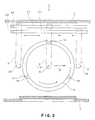
- Fig. 2 is a horizontal cross sectional view of a main part of the substrate processing apparatus shown in Fig. 1;
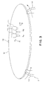
- Fig. 3 is a perspective view of assistance in explaining actions of a fluid nozzle and an inert gas nozzle of the substrate processing apparatus shown in Fig. 1;
- Fig. 4 is a perspective view of assistance in explaining actions of a process liquid nozzle, a fluid nozzle, and an inert gas nozzle of another embodiment of the substrate processing apparatus according to the present invention;
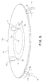
- Fig. 5 is a perspective view of assistance in explaining actions of a fluid nozzle and an inert gas nozzle of another embodiment of the substrate processing apparatus according to the present invention;
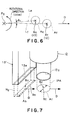
- Fig. 6 is a plan view of assistance in explaining an arrangement of a fluid nozzle and an inert gas nozzle of another embodiment of the substrate processing apparatus according to the present invention;
- Fig. 7 is a perspective view of assistance in explaining a difference in an opening size (shape) of a fluid nozzle and that of an inert gas nozzle of another embodiment of the substrate processing apparatus according to the present invention; and
- Fig. 8 is a schematic view of another embodiment of the substrate processing apparatus according to the present invention.
- Preferred embodiments of the present invention will be described hereinbelow, based on a substrate processing apparatus for cleaning a surface of a substantially disk-shaped wafer W as a substrate.
As shown in Fig. 1, asubstrate processing apparatus 1 in this embodiment includes aprocess vessel 2 in which aspin chuck 3 is disposed to substantially horizontally hold the wafer W and rotate the same. There is disposed achemical liquid nozzle 5 for supplying a chemical liquid to the wafer W. The chemicalliquid nozzle 5 is supported by afirst support arm 6. There are disposed a processliquid nozzle 11 for supplying a rinse liquid as a process liquid, afluid nozzle 12 for supplying a drying fluid having a higher volatility than that of the rinse liquid, and aninert gas nozzle 13 for supplying nitrogen (N2) gas as an inert gas. Thenozzles second support arm 15. Acontroller 16 including a CPU is disposed to control the respective elements of thesubstrate processing apparatus 1. - Three
holding members 18 are disposed above thespin chuck 3. Theholding members 18 are adapted to be in contact with a periphery of the wafer W at three points so as to hold the waferW. A motor 20 is disposed below thespin chuck 3 to rotate the same through a vertical rotational shaft. When thespin chuck 3 is rotated by themotor 20, the wafer W together with thespin chuck 3 is rotated in substantially a horizontal plane about a center Po of the wafer W. Driving of themotor 20 is controlled by thecontroller 16. - The
first support arm 6 is disposed above the wafer W supported by thespin chuck 3. A proximal end of thesupport arm 6 is supported to be capable of moving along aguide rail 31 which is substantially horizontally placed. Adriving mechanism 32 is disposed for moving thesupport arm 6 along theguide rail 31. As shown in Fig. 2, along with a movement of thefirst support arm 6 which is driven by thedriving mechanism 32, the chemicalliquid nozzle 5 can horizontally, radially move outside the wafer W relative to the rotational center Po of the wafer W. Driving of thedriving mechanism 32 is controlled by the controller 16 (Fig. 1). - As shown in Fig. 1, the chemical
liquid nozzle 5 is attached to a lower end of an elevatingshaft 36 extending downward from an elevatingmechanism 35 that is fixed on a distal end of thefirst support arm 6. The elevatingshaft 36 is capable of vertically moving by the elevatingmechanism 35, such that a position of theliquid nozzle 5 is set at a given height. Driving of the elevatingmechanism 35 is controlled by thecontroller 16. An on-offvalve 38 is disposed on a chemicalliquid supply channel 37 that is connected to the chemicalliquid nozzle 5. On-off actions of the on-offvalve 38 are controlled by thecontroller 16. - The
second support arm 15 is disposed above the wafer W supported by thespin chuck 3. A proximal end of thesecond support arm 15 is supported to be capable of moving along aguide rail 51 which is substantially horizontally placed. Adriving mechanism 52 is disposed for moving thesecond support arm 15 along theguide rail 51. These members constitute a nozzle moving mechanism that horizontally moves the processliquid nozzle 11, thefluid nozzle 12, and theinert gas nozzle 13. As shown in Fig. 2, along with the movement of thesecond support arm 15 which is driven by thedriving mechanism 52, the processliquid nozzle 11, thefluid nozzle 12, and theinert gas nozzle 13 can horizontally, radially move outside the wafer W relative to the rotational center Po of the wafer W. Driving of thedriving mechanism 52 is controlled by the controller 16 (Fig. 1). - As shown in Fig. 1, an elevating
mechanism 55 provided with an elevatingshaft 54 is fixed on a distal end of thesecond support arm 15. The elevatingshaft 54 extends downward from the elevatingmechanism 55. The processliquid nozzle 11, thefluid nozzle 12, and theinert gas nozzle 13 are attached to a lower end of the elevatingshaft 54. The elevatingshaft 54 is driven by the elevatingmechanism 55 to expand and contract, such that the processliquid nozzle 11, thefluid nozzle 12, and theinert gas nozzle 13 are set at a given height. Driving of the elevatingmechanism 55 is controlled by thecontroller 16. That is, based on instructions from thecontroller 16, driving of thedriving mechanism 52 is controlled so as to move thesecond support arm 15, thefluid nozzle 12, and theinert gas nozzle 13 in the horizontal direction (nozzle moving direction D), while driving of the elevatingmechanism 55 is controlled so as to adjust positions of the processliquid nozzle 11, thefluid nozzle 12, and theinert gas nozzle 13 in the vertical direction. - As shown in Fig. 3, the process
liquid nozzle 11, thefluid nozzle 12, and theinert gas nozzle 13 are adjacently aligned in the radial direction (nozzle moving direction D) opposite the chemicalliquid nozzle 5 relative to the rotational center Po of the wafer W. That is, in the nozzle moving direction D, theinert gas nozzle 13 is positioned nearer to the rotational center Po of the wafer W than thefluid nozzle 12, and the processliquid nozzle 11 is positioned farther away from the rotational center Po of the wafer W than thefluid nozzle 12. - The process
liquid nozzle 11 supplies a liquid such as deionized water (DIW) as a rinse liquid to liquid-process the wafer W. The processliquid nozzle 11 is connected to a rinseliquid supply source 61 through a rinseliquid supply channel 62. An on-offvalve 63 is disposed on the rinseliquid supply channel 62. It is preferable to use, as a drying fluid which is supplied from thefluid nozzle 12, an IPA solution in which IPA (isopropyl alcohol) is diluted with a deionized water mixed therein. Mixing of a deionized water to dilute IPA is economically advantageous in that an amount of IPA to be used can be further decreased. Thefluid nozzle 12 is connected to a dryingfluid supply source 66 through afluid supply channel 67. An on-offvalve 68 is disposed on thefluid supply channel 67. Theinert gas nozzle 13 is connected to a nitrogengas supply source 71 through a nitrogengas supply channel 72. An on-offvalve 73 is disposed on the nitrogengas supply channel 72. On-off actions of the on-offvalves controller 16 to control supply of a rinse liquid, an IPA solution, and nitrogen gas. - Now, a method for processing a wafer W conducted by the
substrate processing apparatus 1 as structured above is described.
First, a wafer, which has not been cleaned yet, is loaded into theprocess vessel 2 by a transfer arm, not shown, and the wafer W is held by thespin chuck 3 as shown in Fig. 1. In order to deliver the wafer W to thespin chuck 3, as indicated by the two-dot chain lines shown in Fig. 2, the first andsecond support arms spin chuck 3. - After the wafer W is held by the
spin chuck 3, thespin chuck 3 is driven in rotation by themotor 20 shown in Fig. 1 to start a rotation of the wafer W. Then, a chemical process step is started to process the wafer W by a chemical liquid. First, as indicated by the chain lines shown in Fig. 2, thefirst support arm 6 is moved such that the chemicalliquid nozzle 5 is positioned above the rotational center Po of the rotating wafer W. Then a chemical liquid is supplied from the chemicalliquid nozzle 5 toward the rotational center Po of the wafer W. The chemical liquid supplied to the rotational center Po is dispersed over the entire upper surface of the wafer W due to the centrifugal force. Thus, a liquid film of the chemical liquid is formed on the upper surface of the wafer W. - Thereafter, the supply of the chemical liquid from the chemical
liquid nozzle 5 is stopped, and thefirst support arm 6 is returned to the standby position outside thespin chuck 3. Then, by leaving the wafer W as it is for a predetermined period of time, the upper surface of the wafer W is processed by the liquid film of the chemical liquid. - Next, a liquid process step is performed to rinse the wafer W. First, as indicated by the chain lines shown in Fig. 2, the
second support arm 15 is moved such that the processliquid nozzle 11 is positioned above the rotational center Po of the wafer W. Then, in order to liquid-process the wafer W, a rinse liquid is supplied from the processliquid nozzle 11 toward the rotational center Po of the wafer W that is rotated at a predetermined rotational speed. The rinse liquid supplied to the rotational center Po is dispersed over the entire surface of the wafer W due to the centrifugal force. Thus, the chemical liquid on the wafer W is washed away to be removed from the upper surface of the wafer W, and a liquid film of the rinse liquid is formed thereon. - After the wafer W is sufficiently rinsed, the supply of the rinse liquid is stopped, and a drying step is started. First, a supply of an IPA solution from the
fluid nozzle 12 is started, and a supply of nitrogen gas from theinert gas nozzle 13 is started. Then, thesecond support arm 15 is moved in the nozzle moving direction D, while continuing to supply the IPA solution and the nitrogen gas from thenozzles fluid nozzle 12 to the upper surface of the wafer, and a supply position Sn of the nitrogen gas supplied from theinert gas nozzle 13 to the upper surface of the wafer, are moved radially outward from the rotational center Po of the wafer W. Since the wafer W is rotated, the upper surface of the wafer W can be entirely sprayed with the IPA solution and the nitrogen gas. - The supply of the IPA solution and the supply of the nitrogen gas may be simultaneously started. For example, by starting the supply of the IPA solution and the nitrogen gas when the
fluid nozzle 12 is moved to a position directly above the rotational center Po of the wafer W, the supply of the IPA solution may be started from the rotational center Po of the wafer W, and the supply of the nitrogen gas may be started from a position slightly behind away from the rotational center Po in the nozzle moving direction D. Alternatively, the supply of the nitrogen gas may be started, after starting the supply of the IPA solution, when theinert gas nozzle 13 is moved to a position directly above the rotational center Po of the wafer W, whereby the supply of the nitrogen gas is started from the rotational center Po of the wafer W. Alternatively, the supply of the IPA liquid and the supply of the nitrogen gas may be started at positions slightly behind away from the rotational center Po in the nozzle moving direction D. - By supplying the IPA solution, the rinse liquid adhered to the upper surface of the wafer W is washed away therefrom. The volatility of IPA mixed in the rinse liquid expedites evaporation of the rinse liquid. Thus, the supply of the IPA solution can efficiently remove the deionized water from the upper surface of the wafer W. The IPA solution supplied on the upper surface of the wafer W flows radially outward on the wafer W due to the centrifugal force. While the supply position Sf of the IPA solution is moved in the nozzle moving direction D, the supply position Sn of the nitrogen gas is maintained nearer to the rotational center Po of the wafer W than the adjacent supply position Sf of the IPA solution. Thus, immediately after the rinse liquid on the upper surface of the wafer W is washed away, the nitrogen gas can be supplied thereon to promote drying of the upper surface of the wafer W.
- Since the upper surface of the wafer W can be efficiently dried, a drying speed can be accelerated, while moderating the IPA consumption. Further, since an oxidation density causing water marks can be lowered, generation of water marks can be avoided.
- When the supply position Sf of the IPA solution reaches a position on a periphery of the wafer W, the supply of the IPA solution from the
fluid nozzle 12 is stopped. Similarly, when the supply position Sn of the nitrogen gas reaches a position on the periphery of the wafer W, the supply of the nitrogen gas from theinert gas nozzle 13 is stopped. Then, the drying step is completed. It is possible to temporarily stay the supply position Sn of the nitrogen gas at a position on the periphery of the wafer W to continue for a while the supply of the nitrogen gas onto the periphery, and then stop the supply of the nitrogen gas. In this case, the wafer can be more reliably dried. - After the drying step is finished, the rotation of the
spin chuck 3 is stopped, and the not-shown transfer arm is allowed to enter theprocess vessel 2. The wafer W is delivered from thespin chuck 3 to the transfer arm, and is then unloaded from theprocess vessel 2. In this manner, a series of processes for the wafer W conducted by thesubstrate processing apparatus 1 are finished. - For example, a storage medium (magnetic storage medium, optical storage medium, semiconductor memory, and so on) which stores a program configured to execute the above-described substrate processing method may be prepared, and the
controller 16 may read the program from the storage medium to execute the same. - As has been described above, in this embodiment, by supplying the IPA solution from the
fluid nozzle 12, the process liquid adhered to the wafer W can be efficiently removed therefrom. In addition, by supplying nitrogen gas from theinert gas nozzle 13, the IPA solution on the wafer W can be efficiently removed therefrom. Therefore, by simultaneously supplying the IPA solution and the nitrogen gas, the wafer W can be efficiently dried. Since the use of nitrogen gas can promote drying of the wafer W, the amount of IPA solution to be used can be lowered. Because of the smaller IPA consumption, a reduction in cost can be accomplished. Moreover, since the wafer W can be efficiently dried, a time required for the drying process can be shortened. - Another embodiment of the present invention shown in Fig. 6 is described below. In this embodiment, the supply position Sn (inert gas nozzle 13) of nitrogen gas to the wafer W is positioned ahead of the supply position Sf (fluid nozzle 12) of an IPA solution to the wafer W, in a rotational direction of the wafer W. In Fig. 6, a supply area of the IPA solution from the
nozzle 12 is depicted by a circle Af indicated by the broken line, and a supply area of the nitrogen gas from thenozzle 13 is depicted by a circle An indicated by the broken line. A center point of the supply area Af is represented by the supply position Sf, and a center point of the supply area An is represented by the supply position Sn. A line Lf connects the supply position Sf and the rotational center Po of the wafer W to each other. A line Ln connects the supply position Sn and the rotational center Po of the wafer W to each other. In this case, the line Ln is displaced from the line Lf at an angle θn which is smaller than 90° in the rotational direction of the wafer W. This design enables that the nitrogen gas following the IPA solution is constantly supplied to the wafer W not only in the radial direction of the wafer W but also in the rotational direction thereof. - Another embodiment of the present invention shown in Fig. 7 is described below. In this embodiment, an opening dimension Bn of an
inert gas nozzle 13' is larger than an opening dimension Bf of thefluid nozzle 12, in a direction perpendicular to the nozzle moving direction D (herein, the direction is in parallel to the surface of the wafer W). To be specific, thefluid nozzle 12 has a circular opening 12a, while theinert gas nozzle 13' has arectangular opening 13a whose long side is longer than a diameter of the circular opening 12a. Thus, the dimension Bn of the supply area An of the inert gas is larger than the dimension Bf of the supply area Af of the IPA solution, in the direction perpendicular to the nozzle moving direction D. This design enables that the IPA solution is effectively washed away by the nitrogen gas. Thus, the drying step can be more efficiently performed. - Another embodiment of the present invention shown in Fig. 8 is described below. In this embodiment, there is further provided a humidity adjusting mechanism for adjusting a humidity around the wafer W held by the
spin chuck 3. As shown in Fig. 8, the humidity adjusting mechanism may be formed by ahumidity adjustor 85 disposed on a ceiling of theprocess vessel 2. Alternatively, the humidity adjusting mechanism may adjust the humidity by evacuating an interior of theprocess vessel 2 while supplying thereinto a dry inert gas. Owing to the humidity adjusting mechanism, the drying step is performed in such conditions that the humidity around the wafer W is lower (e.g., relative humidity of about 25%) than the humidity at the chemical process step and the liquid process step. This design enables that, when an IPA solution is supplied to the wafer W, the moisture surrounding the wafer W is inhibited from dissolving in the IPA solution. Thus, it is possible to prevent generation of particles on the wafer W that has been subjected to the drying process. - Although the preferred embodiments of the present invention have been described, the present invention is not limited to the above embodiments. For example, not limited to a semiconductor wafer, a substrate may be a glass substrate for an LCD, a CD substrate, a print substrate, a ceramic substrate, and so on.
- The method has been described in which the wafer W is processed by a chemical liquid supplied from the chemical
liquid nozzle 5, and is then cleaned by a process liquid. However, the method for cleaning the wafer W is not limited thereto. For example, the present invention can be suitably applied to a substrate processing apparatus that cleans a wafer W by rubbing the same with a scriber such as a brush and a sponge. Alternatively, the present invention can be applied to a substrate processing apparatus that performs various other processes, such as a resist removing process and a process for removing etching residues. For example, a nozzle for supplying a chemical liquid that removes a resist may be provided to remove a resist. Following to the resist removing process, the chemical liquid process, the rinse process, and the drying process, described in the above embodiment, may be conducted. - Although an IPA solution made by diluting an IPA liquid with a deionized water is taken as an example of a drying fluid, an undiluted IPA liquid can be used. In addition to a liquid state, the fluid may take an atomized state, a jet-flow state, and a vaporous state. For example, a mist of IPA liquid, a mist of IPA solution, an IPA vapor, or a vapor of IPA solution (mixed vapor in which IPA vapor and water vapor are mixed) may be used as the fluid. Besides, a gas such as nitrogen gas is mixed in a mist of IPA liquid, a mist of IPA solution, a vapor of IPA, or a vapor of IPA solution, and the mixture may be used as the drying fluid. When using an IPA solution or a mist or vapor of IPA solution, the ratio of the IPA liquid to the deionized water in the IPA solution may be 1 : 1, for example.
- In place of the IPA, a solvent having a higher volatility, such as water-solvent alcohols including methanol and ethanol, or acetone may be used, for example. When such a solvent is used as the drying fluid, an amount of the fluid to be used can be decreased according to the present invention, so that costs can be reduced. The drying fluid is preferably soluble in a rinse liquid. In this case, by mixing the drying fluid in a rinse liquid, evaporation of the rinse liquid can be helped. Furthermore, the drying fluid may have a function for reducing a surface tension of the rinse liquid, when the drying fluid is mixed in the rinse liquid. This function facilitates removal of the rinse liquid from a surface of the wafer W. Thus, the rinse liquid can be efficiently removed and the wafer W can be easily dried.
- A two-fluid nozzle may be used as the
fluid nozzle 12. For example, a liquid, such as an IPA liquid or IPA solution, and a gas, such as nitrogen gas are mixed inside the two-fluid nozzle to form an IPA liquid or IPA solution into a jet-flow of a number of particulate droplets. The droplets are accelerated by the gas and jetted from the tow-fluid nozzle. A structure of the two-fluid nozzle is not limited to an internal mixing type, but may be a structure of an external mixing type in which a liquid and a gas are mixed outside. - Although there has been described the process in which a rinse liquid is supplied to the wafer W from the process
liquid nozzle 11, then the supply of the rinse liquid is stopped, and thereafter an IPA solution and nitrogen gas are supplied to carry out a drying process, the present invention is not limited thereto. For example, as in another embodiment shown in Fig. 4, an IPA solution and nitrogen gas may be supplied, while supplying a rinse liquid. That is, thesecond support arm 15 may be moved in the nozzle moving direction D, while a rinse liquid, an IPA solution, and nitrogen gas are simultaneously supplied from the processliquid nozzle 11, thefluid nozzle 12, and theinert gas nozzle 13, respectively. Thus, the supply position Sr of the rinse liquid, the supply position Sf of the IPA solution, and the supply position Sn of the nitrogen gas may be simultaneously moved on the upper surface of the wafer W in the nozzle moving direction D. - In the embodiment shown in Fig. 4, the rinse liquid supplied to the upper surface of the wafer W flows radially outward due to the centrifugal force. The IPA solution supplied to the position Sf adjacent to the supply position Sr of the rinse liquid washes away the rinse liquid. Thus, even when the chemical liquid remains on the upper surface of the wafer W, the remaining chemical liquid can be efficiently washed away by the rinse liquid and the IPA solution. In addition, before the rinse liquid is removed from the upper surface of the wafer W, i.e., before the surface of the wafer W is exposed, the rinse liquid is promptly replaced by the IPA solution supplied to the supply position Sf. Namely, since the supply of the IPA solution efficiently removes the rinse liquid from the upper surface of the wafer W, generation of water marks can be decreased. Further, the nitrogen gas supplied to the supply position Sn promotes drying of the IPA solution. Consequently, also in this embodiment, the upper surface of the wafer W can be efficiently dried. As described above, the simultaneous supply of the rinse liquid, the IPA solution, and the nitrogen gas makes it possible to successively rinse and dry the wafer W radially outward from the rotational center Po thereof. This structure can shorten a time required for the drying process.
- The process
liquid nozzle 11, thefluid nozzle 12, and theinert gas nozzle 13 are supported by the singlesecond support arm 15. However, thenozzles liquid nozzle 11, thefluid nozzle 12, and theinert gas nozzle 13 may be radially moved in different directions. - For example, there are separately disposed a support arm for supporting the
fluid nozzle 12 and a support arm for supporting theinert gas nozzle 13. At the drying process, the respective support arms are radially moved in different directions at an angle of 180° by a control of thecontroller 16. Thus, as shown in Fig. 5, thefluid nozzle 12 and theinert gas nozzle 13 are moved radially outward in different directions at an angle of 180° from the rotational center Po of the wafer W. Also in this case, the supply position Sn of the nitrogen gas is maintained at a position nearer to the rotational center Po of the wafer W than the supply position Sf of the IPA solution. That is, a distance between the supply position Sn of the nitrogen gas and the rotational center Po is controlled to be constantly shorter than a distance between the supply position Sf of the IPA solution and the rotational center Po. - Also in this case, when the wafer is rotated to move the IPA solution which has been supplied at the supply position Sf on the upper surface of the wafer W toward the supply position Sn of the nitrogen gas, the IPA solution is blown off toward an outer periphery of the wafer W by the nitrogen gas supplied from the side of the rotational center Po, so that the wafer is dried. Therefore, the wafer W can be efficiently dried. Alternatively, by separately providing a support arm for supporting the process
liquid nozzle 11, the support arm may be moved radially outward such that the supply position Sr of the rinse liquid is maintained farther away from the rotational center Po of the wafer W than the supply position Sf of the IPA solution. In this case, the supply position Sr of the rinse liquid may be aligned with the supply position Sf of the IPA solution in the same radial direction.
Claims (14)
- A substrate processing method comprising:a liquid-processing step of processing a substrate by a process liquid; anda drying step of drying the substrate by supplying to the substrate a drying fluid having a higher volatility than that of the process liquid and an inert gas, while rotating the substrate with the process liquid adhering thereto; whereinat the drying step, a supply position of the fluid to the substrate and a supply position of the inert gas to the substrate are moved radially outward relative to a rotational center of the substrate, respectively, while maintaining the supply position of the inert gas nearer to the rotational center of the substrate than the supply position of the fluid.
- The substrate processing method according to claim 1, wherein
the liquid-processing step and the drying step are successively performed radially outward relative to the rotational center of the substrate, by supplying the process liquid to the substrate while moving a supply position of the process liquid to the substrate radially outward relative to the rotational center of the substrate, with maintaining the supply position of the process liquid farther away from the rotational center of the substrate than the supply position of the fluid to the substrate. - The substrate processing method according to Claim 1, wherein
the supply position of the inert gas to the substrate is positioned ahead of the supply position of the fluid to the substrate, in a rotational direction of the substrate. - The substrate processing method according to claim 1, wherein
the drying step is performed under conditions that a humidity around the substrate is lower than that at the liquid-processing step. - The substrate processing method according to claim 1, wherein
the drying fluid is selected from the group consisting of an IPA liquid, an IPA solution diluted with water, a mist of IPA liquid, a mist of IPA solution diluted with water, an IPA vapor, and a vapor of IPA solution diluted with water. - The substrate processing method according to claim 1, wherein
the process liquid is a rinse liquid. - A substrate processing apparatus comprising:a spin chuck configured to hold a substrate and rotate the same;a process liquid supply system configured to supply a process liquid to the substrate rotated by the spin chuck;a fluid nozzle configured to supply a drying fluid having a higher volatility than that of the process liquid;an inert gas nozzle configured to supply an inert gas to the substrate; anda nozzle moving mechanism configured to move the fluid nozzle and the inert gas nozzle radially outward relative to a rotational center of the substrate, while maintaining the inert gas nozzle nearer to the rotational center of the substrate than the fluid nozzle.
- The substrate processing apparatus according to claim 7, wherein
an opening dimension of the inert gas nozzle is larger than an opening dimension of the fluid nozzle, in a direction perpendicular to a moving direction of the nozzles moved by the nozzle moving mechanism. - The substrate processing apparatus according to claim 7, wherein
the process liquid supply system includes:a process liquid nozzle configured to supply the process liquid to the substrate; anda nozzle moving mechanism configured to move the process liquid nozzle radially outward relative to the rotational center of the substrate, while maintaining the process liquid nozzle farther away from the rotational center of the substrate than the fluid nozzle. - The substrate processing apparatus according to claim 7, further comprising a humidity adjusting mechanism configured to adjust a humidity around the substrate held by the spin chuck.
- The substrate processing apparatus according to claim 7, wherein
the drying fluid is selected from the group consisting of an IPA liquid, an IPA solution diluted with water, a mist of IPA liquid, a mist of IPA solution diluted with water, an IPA vapor, and a vapor of IPA solution diluted with water. - The substrate processing apparatus according to claim 7, wherein
the process liquid is a rinse liquid. - A storage medium for storing a program configured to execute a substrate processing method comprising:a liquid-processing step of processing the substrate by a process liquid; anda drying step of drying the substrate by supplying to the substrate a drying fluid having a higher volatility than that of the process liquid and an inert gas, while rotating the substrate with the process liquid adhering thereto; whereinat the drying step, a supply position of the fluid to the substrate and a supply position of the inert gas to the substrate are moved radially outward relative to a rotational center of the substrate, respectively, while maintaining the supply position of the inert gas nearer to the rotational center of the substrate than the supply position of the fluid.
- The storage medium according to claim 13, wherein in the substrate processing method executed by the program stored in the storage medium, the liquid-processing step and the drying step are successively performed radially outward relative to the rotational center of the substrate, by supplying the process liquid to the substrate while moving a supply position of the process liquid to the substrate radially outward relative to the rotational center of the substrate, with maintaining the supply position of the process liquid farther away from the rotational center of the substrate than the supply position of the fluid to the substrate.
Applications Claiming Priority (2)
| Application Number | Priority Date | Filing Date | Title |
|---|---|---|---|
| JP2004297784 | 2004-10-12 | ||
| PCT/JP2005/018770 WO2006041077A1 (en) | 2004-10-12 | 2005-10-12 | Substrate processing method and substrate processing apparatus |
Publications (2)
| Publication Number | Publication Date |
|---|---|
| EP1801860A1 true EP1801860A1 (en) | 2007-06-27 |
| EP1801860A4 EP1801860A4 (en) | 2009-08-12 |
Family
ID=36148365
Family Applications (1)
| Application Number | Title | Priority Date | Filing Date |
|---|---|---|---|
| EP05793595A Withdrawn EP1801860A4 (en) | 2004-10-12 | 2005-10-12 | SUBSTRATE PROCESSING METHOD AND SUBSTRATE PROCESSING APPARATUS |
Country Status (6)
| Country | Link |
|---|---|
| US (2) | US8337659B2 (en) |
| EP (1) | EP1801860A4 (en) |
| JP (3) | JP4451450B2 (en) |
| KR (1) | KR100766844B1 (en) |
| TW (1) | TWI286353B (en) |
| WO (1) | WO2006041077A1 (en) |
Cited By (2)
| Publication number | Priority date | Publication date | Assignee | Title |
|---|---|---|---|---|
| US8043469B2 (en) | 2006-10-06 | 2011-10-25 | Tokyo Electron Limited | Substrate processing method, substrate processing apparatus, and storage medium |
| US8133327B2 (en) | 2006-03-29 | 2012-03-13 | Tokyo Electron Limited | Substrate processing method, storage medium and substrate processing apparatus |
Families Citing this family (49)
| Publication number | Priority date | Publication date | Assignee | Title |
|---|---|---|---|---|
| TWI286353B (en) | 2004-10-12 | 2007-09-01 | Tokyo Electron Ltd | Substrate processing method and substrate processing apparatus |
| JP4527660B2 (en) | 2005-06-23 | 2010-08-18 | 東京エレクトロン株式会社 | Substrate processing method and substrate processing apparatus |
| JP4781834B2 (en) * | 2006-02-07 | 2011-09-28 | 大日本スクリーン製造株式会社 | Developing apparatus and developing method |
| JP4812563B2 (en) * | 2006-08-29 | 2011-11-09 | 大日本スクリーン製造株式会社 | Substrate processing method and substrate processing apparatus |
| JP4884136B2 (en) * | 2006-08-30 | 2012-02-29 | 東京エレクトロン株式会社 | Liquid processing apparatus and liquid processing method |
| JP4762098B2 (en) * | 2006-09-28 | 2011-08-31 | 大日本スクリーン製造株式会社 | Substrate processing apparatus and substrate processing method |
| JP4884180B2 (en) * | 2006-11-21 | 2012-02-29 | 東京エレクトロン株式会社 | Substrate processing apparatus and substrate processing method |
| JP5014811B2 (en) * | 2007-01-22 | 2012-08-29 | 東京エレクトロン株式会社 | Substrate processing method |
| JP5096849B2 (en) * | 2007-09-13 | 2012-12-12 | 株式会社Sokudo | Substrate processing apparatus and substrate processing method |
| US8567420B2 (en) * | 2008-03-31 | 2013-10-29 | Kabushiki Kaisha Toshiba | Cleaning apparatus for semiconductor wafer |
| JP5270251B2 (en) * | 2008-08-06 | 2013-08-21 | 大日本スクリーン製造株式会社 | Substrate processing equipment |
| JP5390873B2 (en) * | 2009-01-28 | 2014-01-15 | 大日本スクリーン製造株式会社 | Substrate processing method and substrate processing apparatus |
| JP2011060954A (en) * | 2009-09-09 | 2011-03-24 | Toshiba Corp | Method for washing semiconductor wafer |
| JP2011135009A (en) * | 2009-12-25 | 2011-07-07 | Tokyo Electron Ltd | Method and apparatus for drying substrate |
| KR101806191B1 (en) | 2010-06-17 | 2017-12-07 | 도쿄엘렉트론가부시키가이샤 | Substrate processing method, storage medium storing computer program for executing substrate processing method and substrate processing apparatus |
| KR101596750B1 (en) | 2010-06-23 | 2016-02-23 | 도쿄엘렉트론가부시키가이샤 | Substrate processing method, storage medium storing computer program for executing substrate processing method and substrate processing apparatus |
| TWI417693B (en) * | 2010-12-15 | 2013-12-01 | Au Optronics Corp | Etching apparatus and method of controlling the same |
| JP5642574B2 (en) * | 2011-01-25 | 2014-12-17 | 東京エレクトロン株式会社 | Liquid processing apparatus and liquid processing method |
| KR101907510B1 (en) * | 2011-11-07 | 2018-10-16 | 삼성전자주식회사 | Method and apparatus for cleaning a substrate |
| JP6148475B2 (en) * | 2013-01-25 | 2017-06-14 | 株式会社東芝 | Semiconductor manufacturing apparatus and semiconductor device manufacturing method |
| US20140231012A1 (en) * | 2013-02-15 | 2014-08-21 | Dainippon Screen Mfg, Co., Ltd. | Substrate processing apparatus |
| JP6454470B2 (en) * | 2013-03-14 | 2019-01-16 | 東京エレクトロン株式会社 | Drying apparatus and drying processing method |
| KR101763505B1 (en) | 2013-03-14 | 2017-07-31 | 도쿄엘렉트론가부시키가이샤 | Method and apparatus for substrate rinsing and drying |
| JP6224515B2 (en) * | 2013-06-07 | 2017-11-01 | 東京エレクトロン株式会社 | Substrate processing apparatus, substrate processing method, and computer-readable recording medium recording substrate processing program |
| JP5867462B2 (en) * | 2013-07-26 | 2016-02-24 | 東京エレクトロン株式会社 | Liquid processing equipment |
| TWI597770B (en) | 2013-09-27 | 2017-09-01 | 斯克林集團公司 | Substrate processing apparatus and substrate processing method |
| US9966281B2 (en) * | 2013-11-15 | 2018-05-08 | Taiwan Semiconductor Manufacturing Company, Ltd. | Methods and systems for chemical mechanical polish cleaning |
| US10410888B2 (en) * | 2014-02-27 | 2019-09-10 | Lam Research Ag | Device and method for removing liquid from a surface of a disc-like article |
| JP6118758B2 (en) * | 2014-05-01 | 2017-04-19 | 東京エレクトロン株式会社 | Substrate processing apparatus, substrate processing method, and computer-readable recording medium recording substrate processing program |
| JP6389089B2 (en) * | 2014-09-18 | 2018-09-12 | 株式会社Screenホールディングス | Substrate processing apparatus and substrate processing method |
| US10026629B2 (en) | 2014-10-17 | 2018-07-17 | Tokyo Electron Limited | Substrate liquid processing apparatus, substrate liquid processing method, and computer-readable storage medium storing substrate liquid processing program |
| JP6484144B2 (en) | 2014-10-17 | 2019-03-13 | 東京エレクトロン株式会社 | Substrate liquid processing apparatus, substrate liquid processing method, and computer readable storage medium storing substrate liquid processing program |
| JP6454245B2 (en) * | 2014-10-21 | 2019-01-16 | 東京エレクトロン株式会社 | Substrate liquid processing method, substrate liquid processing apparatus, and computer readable storage medium storing substrate liquid processing program |
| US20170084470A1 (en) * | 2015-09-18 | 2017-03-23 | Tokyo Electron Limited | Substrate processing apparatus and cleaning method of processing chamber |
| JP6559602B2 (en) * | 2015-09-18 | 2019-08-14 | 東京エレクトロン株式会社 | Substrate processing apparatus and processing chamber cleaning method |
| JP6588819B2 (en) * | 2015-12-24 | 2019-10-09 | 株式会社Screenホールディングス | Substrate processing apparatus and substrate processing method |
| JP6466315B2 (en) * | 2015-12-25 | 2019-02-06 | 東京エレクトロン株式会社 | Substrate processing method and substrate processing system |
| JP6569574B2 (en) * | 2016-03-24 | 2019-09-04 | 東京エレクトロン株式会社 | Substrate processing apparatus, substrate processing method, and storage medium |
| JP6687486B2 (en) | 2016-08-31 | 2020-04-22 | 株式会社Screenホールディングス | Substrate processing method |
| JP6400766B2 (en) * | 2017-03-23 | 2018-10-03 | 東京エレクトロン株式会社 | Liquid processing method, liquid processing apparatus, and storage medium |
| JP6869093B2 (en) * | 2017-04-27 | 2021-05-12 | 株式会社Screenホールディングス | Substrate processing equipment and substrate processing method |
| JP6938248B2 (en) * | 2017-07-04 | 2021-09-22 | 東京エレクトロン株式会社 | Substrate processing equipment, substrate processing method and storage medium |
| CN107470225A (en) * | 2017-08-28 | 2017-12-15 | 广州沃安实业有限公司 | A kind of cleaning machine |
| JP7034634B2 (en) * | 2017-08-31 | 2022-03-14 | 株式会社Screenホールディングス | Board processing method and board processing equipment |
| GB201815163D0 (en) * | 2018-09-18 | 2018-10-31 | Lam Res Ag | Wafer washing method and apparatus |
| JP7166953B2 (en) * | 2019-02-18 | 2022-11-08 | 東京エレクトロン株式会社 | SUBSTRATE PROCESSING APPARATUS AND SUBSTRATE PROCESSING METHOD |
| CN112859548B (en) * | 2019-11-27 | 2024-03-26 | 长鑫存储技术有限公司 | Developing device and developing method thereof |
| KR20250069975A (en) * | 2020-03-05 | 2025-05-20 | 도쿄엘렉트론가부시키가이샤 | Substrate processing method, and substrate processing device |
| JP7143465B2 (en) * | 2021-03-15 | 2022-09-28 | 東京エレクトロン株式会社 | SUBSTRATE PROCESSING APPARATUS AND SUBSTRATE PROCESSING METHOD |
Family Cites Families (33)
| Publication number | Priority date | Publication date | Assignee | Title |
|---|---|---|---|---|
| JP2556733B2 (en) * | 1988-08-08 | 1996-11-20 | 東京エレクトロン株式会社 | Semiconductor wafer dryer |
| JPH04179227A (en) * | 1990-11-14 | 1992-06-25 | Hitachi Ltd | Drying apparatus |
| JPH069130A (en) | 1992-06-24 | 1994-01-18 | Fuji Kiki Kogyo Kk | Structure of shaft-end member of resin coating roller and resin coating roller |
| JP3402932B2 (en) | 1995-05-23 | 2003-05-06 | 東京エレクトロン株式会社 | Cleaning method and apparatus |
| TW386235B (en) * | 1995-05-23 | 2000-04-01 | Tokyo Electron Ltd | Method for spin rinsing |
| JPH0969488A (en) | 1995-08-30 | 1997-03-11 | Hitachi Ltd | Drying method and device |
| JP3470501B2 (en) | 1996-04-24 | 2003-11-25 | ソニー株式会社 | Semiconductor wafer centrifugal drying method |
| US5882466A (en) | 1996-08-08 | 1999-03-16 | Minnesota Mining And Manufacturing Company | Aqueous bonding composition |
| TW383414B (en) * | 1997-03-05 | 2000-03-01 | Tokyo Electron Ltd | Photoresist agent processing method and photoresist agent processing system and evaluation method and processing apparatus for photoresist agent film |
| US6247479B1 (en) * | 1997-05-27 | 2001-06-19 | Tokyo Electron Limited | Washing/drying process apparatus and washing/drying process method |
| DE69832567T2 (en) | 1997-09-24 | 2007-01-18 | Interuniversitair Micro-Electronica Centrum Vzw | Method and apparatus for removing liquid from the surface of a rotating substrate |
| US6491764B2 (en) | 1997-09-24 | 2002-12-10 | Interuniversitair Microelektronics Centrum (Imec) | Method and apparatus for removing a liquid from a surface of a rotating substrate |
| JP3381776B2 (en) * | 1998-05-19 | 2003-03-04 | 東京エレクトロン株式会社 | Processing device and processing method |
| JP2000058498A (en) | 1998-08-17 | 2000-02-25 | Seiko Epson Corp | Wafer drying method, drying tank, cleaning tank and cleaning apparatus |
| US6092937A (en) | 1999-01-08 | 2000-07-25 | Fastar, Ltd. | Linear developer |
| JP3322853B2 (en) | 1999-08-10 | 2002-09-09 | 株式会社プレテック | Substrate drying device and cleaning device, and drying method and cleaning method |
| US6333275B1 (en) * | 1999-10-01 | 2001-12-25 | Novellus Systems, Inc. | Etchant mixing system for edge bevel removal of copper from silicon wafers |
| JP4069316B2 (en) * | 2000-07-24 | 2008-04-02 | 東京エレクトロン株式会社 | Cleaning processing method and cleaning processing apparatus |
| US6863741B2 (en) | 2000-07-24 | 2005-03-08 | Tokyo Electron Limited | Cleaning processing method and cleaning processing apparatus |
| JP3694641B2 (en) * | 2000-08-09 | 2005-09-14 | 東京エレクトロン株式会社 | Substrate processing apparatus, development processing apparatus, and development processing method |
| JP2003059894A (en) * | 2001-06-05 | 2003-02-28 | Dainippon Screen Mfg Co Ltd | Wafer processing system |
| US6858091B2 (en) * | 2001-07-13 | 2005-02-22 | Lam Research Corporation | Method for controlling galvanic corrosion effects on a single-wafer cleaning system |
| JP3958539B2 (en) * | 2001-08-02 | 2007-08-15 | 東京エレクトロン株式会社 | Substrate processing apparatus and substrate processing method |
| JP4056858B2 (en) | 2001-11-12 | 2008-03-05 | 東京エレクトロン株式会社 | Substrate processing equipment |
| JP2003197590A (en) | 2001-12-21 | 2003-07-11 | Dainippon Screen Mfg Co Ltd | Substrate processing apparatus and substrate processing method |
| JP3958572B2 (en) * | 2001-12-26 | 2007-08-15 | 東京エレクトロン株式会社 | Substrate processing apparatus and substrate processing method |
| JP3993048B2 (en) | 2002-08-30 | 2007-10-17 | 大日本スクリーン製造株式会社 | Substrate processing equipment |
| KR100493849B1 (en) | 2002-09-30 | 2005-06-08 | 삼성전자주식회사 | Apparatus for drying a wafer |
| AT501653B1 (en) | 2003-11-18 | 2010-04-15 | Tokyo Electron Ltd | SUBSTRATE CLEANING PROCESS, SUBSTRATE CLEANING DEVICE AND COMPUTER-READABLE RECORDING MEDIUM |
| JP2005159191A (en) | 2003-11-28 | 2005-06-16 | Sony Corp | Substrate cleaning device |
| TWI286353B (en) * | 2004-10-12 | 2007-09-01 | Tokyo Electron Ltd | Substrate processing method and substrate processing apparatus |
| JP4527660B2 (en) * | 2005-06-23 | 2010-08-18 | 東京エレクトロン株式会社 | Substrate processing method and substrate processing apparatus |
| JP5143498B2 (en) * | 2006-10-06 | 2013-02-13 | 東京エレクトロン株式会社 | Substrate processing method, substrate processing apparatus, program, and recording medium |
-
2005
- 2005-10-11 TW TW094135376A patent/TWI286353B/en not_active IP Right Cessation
- 2005-10-12 JP JP2006540941A patent/JP4451450B2/en not_active Expired - Lifetime
- 2005-10-12 WO PCT/JP2005/018770 patent/WO2006041077A1/en not_active Ceased
- 2005-10-12 KR KR1020067012237A patent/KR100766844B1/en not_active Expired - Lifetime
- 2005-10-12 US US11/578,099 patent/US8337659B2/en active Active
- 2005-10-12 EP EP05793595A patent/EP1801860A4/en not_active Withdrawn
-
2009
- 2009-11-05 JP JP2009254293A patent/JP5068801B2/en not_active Expired - Lifetime
-
2012
- 2012-02-07 JP JP2012024127A patent/JP5318980B2/en not_active Expired - Lifetime
- 2012-12-04 US US13/693,712 patent/US8794250B2/en not_active Expired - Lifetime
Cited By (3)
| Publication number | Priority date | Publication date | Assignee | Title |
|---|---|---|---|---|
| US8133327B2 (en) | 2006-03-29 | 2012-03-13 | Tokyo Electron Limited | Substrate processing method, storage medium and substrate processing apparatus |
| US8043469B2 (en) | 2006-10-06 | 2011-10-25 | Tokyo Electron Limited | Substrate processing method, substrate processing apparatus, and storage medium |
| DE102007047437B4 (en) * | 2006-10-06 | 2013-10-17 | Tokyo Electron Ltd. | Substrate processing method, substrate processing device and storage medium |
Also Published As
| Publication number | Publication date |
|---|---|
| KR20060132848A (en) | 2006-12-22 |
| TWI286353B (en) | 2007-09-01 |
| US20130145643A1 (en) | 2013-06-13 |
| KR100766844B1 (en) | 2007-10-17 |
| JP2010045389A (en) | 2010-02-25 |
| JP2012099862A (en) | 2012-05-24 |
| JP5318980B2 (en) | 2013-10-16 |
| JPWO2006041077A1 (en) | 2008-05-15 |
| US20070223342A1 (en) | 2007-09-27 |
| JP5068801B2 (en) | 2012-11-07 |
| JP4451450B2 (en) | 2010-04-14 |
| TW200627537A (en) | 2006-08-01 |
| WO2006041077A1 (en) | 2006-04-20 |
| US8794250B2 (en) | 2014-08-05 |
| US8337659B2 (en) | 2012-12-25 |
| EP1801860A4 (en) | 2009-08-12 |
Similar Documents
| Publication | Publication Date | Title |
|---|---|---|
| US8794250B2 (en) | Substrate processing method and substrate processing apparatus | |
| US7806989B2 (en) | Substrate processing method and substrate processing apparatus | |
| US7803230B2 (en) | Substrate cleaning apparatus, substrate cleaning method, and medium for recording program used for the method | |
| CN102339774B (en) | Substrate cleaning apparatus, coating and developing apparatus having the same and substrate cleaning method | |
| JP6013289B2 (en) | Semiconductor substrate cleaning method and semiconductor substrate cleaning apparatus | |
| JP7727760B2 (en) | Substrate processing method and substrate processing apparatus | |
| US8545640B2 (en) | Substrate processing method, storage medium storing computer program for performing substrate processing method, and substrate processing apparatus | |
| JP3035450B2 (en) | Substrate cleaning method | |
| CN112439737A (en) | Apparatus and method for processing substrate | |
| US6823876B1 (en) | Methodology of rotational etching tool maintenance | |
| US20260033284A1 (en) | Substrate processing apparatus | |
| US20250065378A1 (en) | Substrate processing apparatus and substrate processing method | |
| US20260005011A1 (en) | Substrate processing method | |
| KR100895319B1 (en) | Substrate processing equipment | |
| JP2024072489A (en) | SUBSTRATE PROCESSING METHOD AND SUBSTRATE PROCESSING SYSTEM | |
| KR20220115980A (en) | Substrate processing method |
Legal Events
| Date | Code | Title | Description |
|---|---|---|---|
| PUAI | Public reference made under article 153(3) epc to a published international application that has entered the european phase |
Free format text: ORIGINAL CODE: 0009012 |
|
| 17P | Request for examination filed |
Effective date: 20061026 |
|
| AK | Designated contracting states |
Kind code of ref document: A1 Designated state(s): AT DE |
|
| DAX | Request for extension of the european patent (deleted) | ||
| RBV | Designated contracting states (corrected) |
Designated state(s): AT DE |
|
| A4 | Supplementary search report drawn up and despatched |
Effective date: 20090714 |
|
| STAA | Information on the status of an ep patent application or granted ep patent |
Free format text: STATUS: THE APPLICATION HAS BEEN WITHDRAWN |
|
| 18W | Application withdrawn |
Effective date: 20130318 |