EP1801839A2 - Magnétron - Google Patents
Magnétron Download PDFInfo
- Publication number
- EP1801839A2 EP1801839A2 EP06126502A EP06126502A EP1801839A2 EP 1801839 A2 EP1801839 A2 EP 1801839A2 EP 06126502 A EP06126502 A EP 06126502A EP 06126502 A EP06126502 A EP 06126502A EP 1801839 A2 EP1801839 A2 EP 1801839A2
- Authority
- EP
- European Patent Office
- Prior art keywords
- yoke
- magnetron
- seal
- disk unit
- magnet
- Prior art date
- Legal status (The legal status is an assumption and is not a legal conclusion. Google has not performed a legal analysis and makes no representation as to the accuracy of the status listed.)
- Granted
Links
Images


Classifications
-
- H—ELECTRICITY
- H01—ELECTRIC ELEMENTS
- H01J—ELECTRIC DISCHARGE TUBES OR DISCHARGE LAMPS
- H01J23/00—Details of transit-time tubes of the types covered by group H01J25/00
- H01J23/36—Coupling devices having distributed capacitance and inductance, structurally associated with the tube, for introducing or removing wave energy
- H01J23/54—Filtering devices preventing unwanted frequencies or modes to be coupled to, or out of, the interaction circuit; Prevention of high frequency leakage in the environment
-
- H—ELECTRICITY
- H01—ELECTRIC ELEMENTS
- H01J—ELECTRIC DISCHARGE TUBES OR DISCHARGE LAMPS
- H01J23/00—Details of transit-time tubes of the types covered by group H01J25/00
- H01J23/14—Leading-in arrangements; Seals therefor
- H01J23/15—Means for preventing wave energy leakage structurally associated with tube leading-in arrangements, e.g. filters, chokes, attenuating devices
-
- H—ELECTRICITY
- H01—ELECTRIC ELEMENTS
- H01J—ELECTRIC DISCHARGE TUBES OR DISCHARGE LAMPS
- H01J25/00—Transit-time tubes, e.g. klystrons, travelling-wave tubes, magnetrons
- H01J25/50—Magnetrons, i.e. tubes with a magnet system producing an H-field crossing the E-field
- H01J25/52—Magnetrons, i.e. tubes with a magnet system producing an H-field crossing the E-field with an electron space having a shape that does not prevent any electron from moving completely around the cathode or guide electrode
- H01J25/58—Magnetrons, i.e. tubes with a magnet system producing an H-field crossing the E-field with an electron space having a shape that does not prevent any electron from moving completely around the cathode or guide electrode having a number of resonators; having a composite resonator, e.g. a helix
-
- H—ELECTRICITY
- H01—ELECTRIC ELEMENTS
- H01J—ELECTRIC DISCHARGE TUBES OR DISCHARGE LAMPS
- H01J2225/00—Transit-time tubes, e.g. Klystrons, travelling-wave tubes, magnetrons
- H01J2225/50—Magnetrons, i.e. tubes with a magnet system producing an H-field crossing the E-field
- H01J2225/52—Magnetrons, i.e. tubes with a magnet system producing an H-field crossing the E-field with an electron space having a shape that does not prevent any electron from moving completely around the cathode or guide electrode
- H01J2225/58—Magnetrons, i.e. tubes with a magnet system producing an H-field crossing the E-field with an electron space having a shape that does not prevent any electron from moving completely around the cathode or guide electrode having a number of resonators; having a composite resonator, e.g. a helix
- H01J2225/587—Multi-cavity magnetrons
Definitions
- the present invention relates to a magnetron, and more particularly, to a magnetron which can simplify an installation process of the choke filter and cut down the manufacturing cost of the choke filter.
- a magnetron is a bipolar vacuum tube consisting of a cylindrical cathode (straight wire) and a coaxial anode, and generating an electric field by impressing a DC voltage between the cathode and the anode.
- a magnetic field is impressed in the length direction of the magnetron by using an external magnet
- the magnetron is operated as an oscillator.
- the magnetron generates a very high frequency or a large output in a short time. Therefore, the magnetron can be used as a main power source of a radar system or a microwave oven.
- the magnetron since the magnetron generates a very high frequency and a large output in a short time, if the radio frequency generated by the magnetron is externally leaked, the radio frequency has the detrimental effects on the human body or the peripheral electronic devices, thereby causing noise.
- the present invention also relates to the researches on the interception of the external leakage of the radio frequency generated by the magnetron.
- a magnetron including: a yoke having a predetermined internal space by coupling an upper yoke to a lower yoke; an upper magnet and a lower magnet housed in the internal space, and fixedly coupled respectively to the inner flat surfaces of the upper yoke and the lower yoke along the width direction of the yoke; an anode cylinder disposed in a space between the upper magnet and the lower magnet, for generating radio frequency energy; a funnel-shaped upper pole piece and a funnel-shaped lower pole piece disposed at the upper and lower opening units of the anode cylinder, respectively; a cylindrical A-seal disposed at the upper portion of the upper pole piece, for intercepting external leakage of a fifth harmonic; and the choke filter with a coupling slot unit bonded to the inner flat surface of the A-seal, for intercepting external leakage of a third harmonic.
- the present invention provides a magnetron, including: a yoke having a predetermined internal space by coupling an upper yoke to a lower yoke; an upper magnet and a lower magnet housed in the internal space, and fixedly coupled respectively to the inner flat surfaces of the upper yoke and the lower yoke along the width direction of the yoke; an anode cylinder disposed in a space between the upper magnet and the lower magnet, for generating radio frequency energy; a funnel-shaped upper pole piece and a funnel-shaped lower pole piece disposed at the upper and lower opening units of the anode cylinder, respectively; a cylindrical A-seal disposed at the upper portion of the upper pole piece, for intercepting external leakage of a fifth harmonic; and the choke filter with a coupling slot unit bonded to the inner flat surface of the A-seal, for intercepting external leakage of a third harmonic.
- Figure 1 is a perspective view illustrating the magnetron in accordance with the present invention
- Figure 2 is a cross-sectional view taken along line II-II of Figure 1
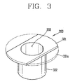
- Figure 3 is a perspective view illustrating the choke filter of Figure 2
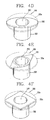
- Figures 4a to 4f are perspective views illustrating various examples of the choke filter in accordance with the present invention
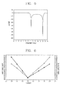
- Figure 5 is a graph showing a harmonic shielding effect of the magnetron in accordance with the present invention
- Figure 6 is a graph showing a noise level by a gap between the A-seal and the choke filter in the magnetron in accordance with the present invention.
- the magnetron 300 having the choke filter 330 includes a yoke 301 having a predetermined internal space by coupling an upper yoke 301a and a lower yoke 301 b, an upper magnet 321 and a lower magnet 322 housed in the internal space, and fixedly coupled respectively to the inner flat surfaces of the upper yoke 301a and the lower yoke 301 b along the width direction of the yoke 301, an anode cylinder 302 disposed in a space between the upper magnet 321 and the lower magnet 322, for generating radio frequency energy, a funnel-shaped upper pole piece 313 and a funnel-shaped lower pole piece 314 disposed at the upper and lower opening units of the anode cylinder 302, respectively, a cylindrical A-seal 315 disposed at the upper portion of the upper pole piece 313, for intercepting external leakage of a fifth harmonic, and the choke filter 330 with a coupling slot unit bonded to the inner flat surface of the A
- the upper yoke 301a and the lower yoke 301b are coupled to form a rectangular side section.
- the cylindrical anode cylinder 302 is installed inside the yoke 301.
- a plurality of vanes 303 forming a hollow resonator for inducing harmonic elements are radially arranged toward the shaft center direction inside the anode cylinder 302.
- Internal pressure equalization rings 304 and external pressure equalization rings 305 are alternately coupled to the upper and lower portions of the front ends of the vanes 303, thereby forming an anode with the anode cylinder 302.
- a filament 307 is spirally wound around the center shaft of the anode cylinder 302 with a predetermined operation space 306 from the front ends of the vanes 303.
- the filament 307 is made of a mixture of tungsten and thoria, for forming a cathode.
- the cathode is heated by an operation current supplied to the filament 307, for emitting thermo-electrons.
- a top shield 308 for intercepting upward emission of the thermo-electrons is fixed to the top end of the filament 307, and a bottom shield 309 for intercepting downward emission of the thermo-electrons is fixed to the bottom end of the filament 307.
- a center lead 310 made of molybdenum is inserted into a through hole formed at the center of the bottom shield 309, and fixedly bonded to the bottom surface of the top shield 308. Also, a top end of a side lead 311 made of molybdenum is bonded to the bottom surface of the bottom shield 309 with a predetermined interval from the center lead 310.
- the funnel-shaped upper pole piece 313 and lower pole piece 314 made of a magnetic material are coupled to the upper and lower opening units of the anode cylinder 302.
- the cylindrical A-seal 315 and F-seal 316 are bonded to the upper portion of the upper pole piece 313 and the lower portion of the lower pole piece 314 by brazing, respectively, for preventing external leakage of the third harmonic elements.
- the choke filter 330 is disposed at the lower portion of the A-seal 315 along the height direction of the magnetron 300, for preventing external leakage of the fifth harmonic elements.
- the coupling slot 331 a is formed at one side of the choke filter 330. As shown in Figure 6, the isolation gap between the A-seal 315 having the minimum noise and the choke filter 330 increases from 0.8mm to 1.6mm. As a result, the magnetron 300 can be easily assembled in a short time.
- the choke filter 330 has a flat disk unit 331 formed with a predetermined width and bonded to one side circumference of the A-seal 315, and a cylinder unit 332 coaxially disposed with the disk unit 331, formed with a smaller diameter than that of the disk unit 331, and extended from the bottom surface of the disk unit 331 by a predetermined length along the thickness direction of the disk unit 331.
- a hollow hole 333 is formed at the center portions of the disk unit 331 and the cylinder unit 332.
- the coupling slot unit is formed at one side of the disk unit 331.
- the coupling slot unit includes a coupling slot 331a formed by cutting one side of the disk unit 331, so that one side flat surface of the disk unit 331 cannot be bonded to the A-seal 315.
- the coupling slot 331 a of the disk unit 331 is formed by cutting part of the flat surface of the disk unit 331 so that the disk unit 331 cannot contact the inner surface of the A-seal 315. Accordingly, the disk unit 331 can be formed in various shapes such as a polygonal shape including a triangle or rectangle, and a curved elliptical shape according to the shape of the coupling slot 331a.
- An A-ceramic 317 for externally outputting a radio frequency and an F-ceramic for hot rolling are bonded to the upper portion of the A-seal 315 and the lower portion of the F-seal 316 by brazing, respectively.
- An exhaust tube 319 is bonded to the upper portion of the A-ceramic 317 by brazing. The top end of the exhaust tube 319 is cut and bonded at the same time, for sealing up the inside of the anode cylinder 302 in a vacuum state.
- An antenna 320 for outputting the radio frequency oscillated in the hollow resonator is installed inside the A-seal 315.
- the bottom end of the antenna 320 is connected to the vanes 303, and the top end thereof is fixed to the inner top surface of the exhaust tube 319.
- the upper magnet 321 and the lower magnet 322 are coupled to the upper and lower portions of the anode cylinder 302 to contact the inner surface of the yoke 301, for generating magnetic fields with the upper pole piece 313 and the lower pole piece 314.
- Cooling fins 323 are installed between the inner circumference of the yoke 301 and the outer circumference of the anode cylinder 302.
- An antenna cap 324 for protecting the bonded portion of the exhaust tube 319 is covered on the upper portion of the A-ceramic 317.
- the closed circuit comprised of the center lead 310, the filament 307, the top shield 308, the bottom shield 309 and the side lead 311 is formed, to supply an operation current to the filament 307.
- the filament 307 is heated by the operation current, thereby emitting the thermo-electrons.
- An electron group is formed by the thermo-electrons.
- a strong electric field is generated in the operation space 306 by a driving voltage supplied to the anode through the side lead 311.
- the magnetic fluxes generated by the upper magnet 321 and the lower magnet 322 are induced to the operation space 306 along the lower pole piece 314, and transferred to the upper pole piece 313 through the operation space 306. Therefore, a high magnetic field is generated in the operation space 306.
- the fifth harmonic is coupled by the A-seal 315, and thus is not externally leaked
- the third harmonic is coupled by the coupling slot 331 a, and thus is not externally leaked.
- thermo-electrons emitted from the surface of the high temperature filament 307 to the operation space 306 receive force in the vertical direction by the strong electric field existing in the operation space 306, spirally perform circular motion, and reach the vanes 303.
- the electron group generated by the electron motion causes interference to the vanes 303 at a period of one divided by an inverse number of a multiple of the periodical oscillation radio frequency.
- inductance elements composed of the facing spaces of the vanes 303 and the anode cylinder 302 form a parallel resonance circuit on the circuit, thereby inducing the radio frequency from the vanes 303.
- the induced radio frequency is externally emitted from the magnetron 300 through the antenna 320, for driving an electronic product such as an electrodeless illumination apparatus or a microwave oven.
Landscapes
- Microwave Tubes (AREA)
Applications Claiming Priority (1)
| Application Number | Priority Date | Filing Date | Title |
|---|---|---|---|
| KR1020050127263A KR100783407B1 (ko) | 2005-12-21 | 2005-12-21 | 초크필터를 구비한 마그네트론 |
Publications (3)
| Publication Number | Publication Date |
|---|---|
| EP1801839A2 true EP1801839A2 (fr) | 2007-06-27 |
| EP1801839A3 EP1801839A3 (fr) | 2008-11-05 |
| EP1801839B1 EP1801839B1 (fr) | 2011-04-20 |
Family
ID=37951955
Family Applications (1)
| Application Number | Title | Priority Date | Filing Date |
|---|---|---|---|
| EP06126502A Not-in-force EP1801839B1 (fr) | 2005-12-21 | 2006-12-19 | Magnétron |
Country Status (5)
| Country | Link |
|---|---|
| US (1) | US7511251B2 (fr) |
| EP (1) | EP1801839B1 (fr) |
| KR (1) | KR100783407B1 (fr) |
| CN (1) | CN100562968C (fr) |
| DE (1) | DE602006021385D1 (fr) |
Families Citing this family (6)
| Publication number | Priority date | Publication date | Assignee | Title |
|---|---|---|---|---|
| JPWO2010097882A1 (ja) * | 2009-02-27 | 2012-08-30 | パナソニック株式会社 | マグネトロン及びマイクロ波利用機器 |
| EP2247160B1 (fr) * | 2009-05-02 | 2012-11-28 | Electrolux Home Products Corporation N.V. | Dispositif d'étanchéité aux micro-ondes de l'ouverture autour d'un arbre rotatif |
| US8264150B2 (en) * | 2009-07-17 | 2012-09-11 | Fusion Uv Systems, Inc. | Modular magnetron |
| CN102820195B (zh) * | 2011-06-07 | 2016-06-29 | 乐金电子(天津)电器有限公司 | 磁控管的天线封盖 |
| RU2551353C1 (ru) * | 2013-11-20 | 2015-05-20 | Федеральное государственное бюджетное образовательное учреждение высшего профессионального образования "Национальный исследовательский Томский политехнический университет" | Релятивистский магнетрон |
| KR102082506B1 (ko) * | 2018-02-09 | 2020-02-27 | 엘지전자 주식회사 | 고조파 차폐 성능이 개선된 마그네트론 |
Citations (6)
| Publication number | Priority date | Publication date | Assignee | Title |
|---|---|---|---|---|
| DE2362734A1 (de) * | 1972-12-18 | 1974-07-04 | Hitachi Ltd | Magnetron |
| JPS60243938A (ja) * | 1984-05-18 | 1985-12-03 | Hitachi Ltd | マグネトロン |
| GB2234390A (en) * | 1989-05-30 | 1991-01-30 | Gold Star Co | Magnetron choke and magnetron including the same |
| GB2326521A (en) * | 1997-06-16 | 1998-12-23 | Lg Electronics Inc | Magnetron with two chokes |
| EP1355340A2 (fr) * | 2002-04-18 | 2003-10-22 | Lg Electronics Inc. | Magnétron |
| EP1391909A2 (fr) * | 2002-07-31 | 2004-02-25 | Matsushita Electric Industrial Co., Ltd. | Magnétron |
Family Cites Families (4)
| Publication number | Priority date | Publication date | Assignee | Title |
|---|---|---|---|---|
| JPS6217973Y2 (fr) * | 1980-04-30 | 1987-05-08 | ||
| KR100209690B1 (ko) * | 1997-05-31 | 1999-07-15 | 구자홍 | 전자레인지용 마그네트론 |
| KR100231037B1 (ko) * | 1997-07-14 | 1999-11-15 | 윤종용 | 마그네트론 |
| KR100774467B1 (ko) * | 2005-12-27 | 2007-11-08 | 엘지전자 주식회사 | 마그네트론의 초크필터 |
-
2005
- 2005-12-21 KR KR1020050127263A patent/KR100783407B1/ko not_active IP Right Cessation
-
2006
- 2006-12-19 EP EP06126502A patent/EP1801839B1/fr not_active Not-in-force
- 2006-12-19 DE DE602006021385T patent/DE602006021385D1/de active Active
- 2006-12-20 US US11/613,531 patent/US7511251B2/en not_active Expired - Fee Related
- 2006-12-21 CN CNB2006101712475A patent/CN100562968C/zh not_active Expired - Fee Related
Patent Citations (6)
| Publication number | Priority date | Publication date | Assignee | Title |
|---|---|---|---|---|
| DE2362734A1 (de) * | 1972-12-18 | 1974-07-04 | Hitachi Ltd | Magnetron |
| JPS60243938A (ja) * | 1984-05-18 | 1985-12-03 | Hitachi Ltd | マグネトロン |
| GB2234390A (en) * | 1989-05-30 | 1991-01-30 | Gold Star Co | Magnetron choke and magnetron including the same |
| GB2326521A (en) * | 1997-06-16 | 1998-12-23 | Lg Electronics Inc | Magnetron with two chokes |
| EP1355340A2 (fr) * | 2002-04-18 | 2003-10-22 | Lg Electronics Inc. | Magnétron |
| EP1391909A2 (fr) * | 2002-07-31 | 2004-02-25 | Matsushita Electric Industrial Co., Ltd. | Magnétron |
Also Published As
| Publication number | Publication date |
|---|---|
| US20070139125A1 (en) | 2007-06-21 |
| CN1988105A (zh) | 2007-06-27 |
| KR20070066275A (ko) | 2007-06-27 |
| EP1801839B1 (fr) | 2011-04-20 |
| US7511251B2 (en) | 2009-03-31 |
| EP1801839A3 (fr) | 2008-11-05 |
| DE602006021385D1 (de) | 2011-06-01 |
| KR100783407B1 (ko) | 2007-12-11 |
| CN100562968C (zh) | 2009-11-25 |
Similar Documents
| Publication | Publication Date | Title |
|---|---|---|
| JP2002124196A (ja) | マグネトロン及びそれを用いた加工装置 | |
| EP1801839B1 (fr) | Magnétron | |
| KR0176847B1 (ko) | 마그네트론 | |
| KR100774467B1 (ko) | 마그네트론의 초크필터 | |
| KR100783409B1 (ko) | 마그네트론 | |
| KR101376621B1 (ko) | 마그네트론 | |
| KR100451235B1 (ko) | 마그네트론의 입력부 차폐구조 | |
| KR100539815B1 (ko) | 마그네트론의 가스켓 링 결합구조 | |
| KR100539816B1 (ko) | 마그네트론의 초크 구조 | |
| KR100836058B1 (ko) | 마그네트론의 안테나 | |
| KR100631734B1 (ko) | 마그네트론의 안테나 조립방법 | |
| KR100189101B1 (ko) | 마그네트론의 애노드 실린더 | |
| KR100664298B1 (ko) | 마그네트론의 마그네트 장착구조 | |
| KR100455195B1 (ko) | 마그네트론의 자계집속구조 | |
| KR200150805Y1 (ko) | 마그네트론 | |
| KR100783408B1 (ko) | 마그네트론의 초크필터 | |
| KR20050000759A (ko) | 마그네트론의 상부폴피스 구조 | |
| KR20030089323A (ko) | 마그네트론의 가스켓 링 설치구조 | |
| KR20040110568A (ko) | 마그네트론의 요크구조 | |
| KR20040110570A (ko) | 마그네트론의 베인 조립구조 | |
| KR20030089322A (ko) | 마그네트론의 요크구조 | |
| KR20030089303A (ko) | 마그네트론의 디스크구조 | |
| KR20040110571A (ko) | 마그네트론의 a-실 고정구조 | |
| KR20060108990A (ko) | 마그네트론의 a-실 접합구조 | |
| KR20040061411A (ko) | 마그네트론의 안테나 캡 설치구조 |
Legal Events
| Date | Code | Title | Description |
|---|---|---|---|
| PUAI | Public reference made under article 153(3) epc to a published international application that has entered the european phase |
Free format text: ORIGINAL CODE: 0009012 |
|
| 17P | Request for examination filed |
Effective date: 20070118 |
|
| AK | Designated contracting states |
Kind code of ref document: A2 Designated state(s): AT BE BG CH CY CZ DE DK EE ES FI FR GB GR HU IE IS IT LI LT LU LV MC NL PL PT RO SE SI SK TR |
|
| AX | Request for extension of the european patent |
Extension state: AL BA HR MK YU |
|
| PUAL | Search report despatched |
Free format text: ORIGINAL CODE: 0009013 |
|
| AK | Designated contracting states |
Kind code of ref document: A3 Designated state(s): AT BE BG CH CY CZ DE DK EE ES FI FR GB GR HU IE IS IT LI LT LU LV MC NL PL PT RO SE SI SK TR |
|
| AX | Request for extension of the european patent |
Extension state: AL BA HR MK RS |
|
| 17Q | First examination report despatched |
Effective date: 20090428 |
|
| R17C | First examination report despatched (corrected) |
Effective date: 20090504 |
|
| AKX | Designation fees paid |
Designated state(s): DE FR GB IT |
|
| GRAP | Despatch of communication of intention to grant a patent |
Free format text: ORIGINAL CODE: EPIDOSNIGR1 |
|
| RIN1 | Information on inventor provided before grant (corrected) |
Inventor name: LEE, JONG-SOO Inventor name: BAEK, SEUNG-WON |
|
| GRAS | Grant fee paid |
Free format text: ORIGINAL CODE: EPIDOSNIGR3 |
|
| GRAA | (expected) grant |
Free format text: ORIGINAL CODE: 0009210 |
|
| AK | Designated contracting states |
Kind code of ref document: B1 Designated state(s): DE FR GB IT |
|
| REG | Reference to a national code |
Ref country code: GB Ref legal event code: FG4D |
|
| REF | Corresponds to: |
Ref document number: 602006021385 Country of ref document: DE Date of ref document: 20110601 Kind code of ref document: P |
|
| REG | Reference to a national code |
Ref country code: DE Ref legal event code: R096 Ref document number: 602006021385 Country of ref document: DE Effective date: 20110601 |
|
| PLBE | No opposition filed within time limit |
Free format text: ORIGINAL CODE: 0009261 |
|
| STAA | Information on the status of an ep patent application or granted ep patent |
Free format text: STATUS: NO OPPOSITION FILED WITHIN TIME LIMIT |
|
| 26N | No opposition filed |
Effective date: 20120123 |
|
| REG | Reference to a national code |
Ref country code: DE Ref legal event code: R097 Ref document number: 602006021385 Country of ref document: DE Effective date: 20120123 |
|
| PG25 | Lapsed in a contracting state [announced via postgrant information from national office to epo] |
Ref country code: IT Free format text: LAPSE BECAUSE OF FAILURE TO SUBMIT A TRANSLATION OF THE DESCRIPTION OR TO PAY THE FEE WITHIN THE PRESCRIBED TIME-LIMIT Effective date: 20110420 |
|
| REG | Reference to a national code |
Ref country code: FR Ref legal event code: PLFP Year of fee payment: 10 |
|
| REG | Reference to a national code |
Ref country code: FR Ref legal event code: PLFP Year of fee payment: 11 |
|
| PGFP | Annual fee paid to national office [announced via postgrant information from national office to epo] |
Ref country code: GB Payment date: 20161110 Year of fee payment: 11 Ref country code: DE Payment date: 20161107 Year of fee payment: 11 Ref country code: FR Payment date: 20161114 Year of fee payment: 11 |
|
| REG | Reference to a national code |
Ref country code: DE Ref legal event code: R119 Ref document number: 602006021385 Country of ref document: DE |
|
| GBPC | Gb: european patent ceased through non-payment of renewal fee |
Effective date: 20171219 |
|
| REG | Reference to a national code |
Ref country code: FR Ref legal event code: ST Effective date: 20180831 |
|
| PG25 | Lapsed in a contracting state [announced via postgrant information from national office to epo] |
Ref country code: FR Free format text: LAPSE BECAUSE OF NON-PAYMENT OF DUE FEES Effective date: 20180102 Ref country code: DE Free format text: LAPSE BECAUSE OF NON-PAYMENT OF DUE FEES Effective date: 20180703 |
|
| PG25 | Lapsed in a contracting state [announced via postgrant information from national office to epo] |
Ref country code: GB Free format text: LAPSE BECAUSE OF NON-PAYMENT OF DUE FEES Effective date: 20171219 |