EP1798622B1 - Verfahren, das ein Absichern der Navigation und/oder der Lenkung und/oder der Steuerung eines Projektils zu einem Ziel ermöglicht, und Vorrichtung, die ein solches Verfahren einsetzt - Google Patents
Verfahren, das ein Absichern der Navigation und/oder der Lenkung und/oder der Steuerung eines Projektils zu einem Ziel ermöglicht, und Vorrichtung, die ein solches Verfahren einsetzt Download PDFInfo
- Publication number
- EP1798622B1 EP1798622B1 EP06291978.2A EP06291978A EP1798622B1 EP 1798622 B1 EP1798622 B1 EP 1798622B1 EP 06291978 A EP06291978 A EP 06291978A EP 1798622 B1 EP1798622 B1 EP 1798622B1
- Authority
- EP
- European Patent Office
- Prior art keywords
- projectile
- magnetic field
- reference frame
- guidance
- value
- Prior art date
- Legal status (The legal status is an assumption and is not a legal conclusion. Google has not performed a legal analysis and makes no representation as to the accuracy of the status listed.)
- Active
Links
- 238000000034 method Methods 0.000 title claims description 27
- 238000010304 firing Methods 0.000 claims description 50
- 238000005259 measurement Methods 0.000 claims description 39
- 238000004364 calculation method Methods 0.000 claims description 30
- 230000015654 memory Effects 0.000 claims description 20
- 238000012937 correction Methods 0.000 claims description 15
- 230000001133 acceleration Effects 0.000 claims description 12
- 230000006870 function Effects 0.000 claims description 10
- 238000004422 calculation algorithm Methods 0.000 claims description 9
- 239000011159 matrix material Substances 0.000 claims description 9
- 238000011156 evaluation Methods 0.000 description 6
- 239000003550 marker Substances 0.000 description 6
- 241000272517 Anseriformes Species 0.000 description 5
- 230000014509 gene expression Effects 0.000 description 4
- 238000010276 construction Methods 0.000 description 3
- 238000010586 diagram Methods 0.000 description 3
- 238000012545 processing Methods 0.000 description 3
- 238000012546 transfer Methods 0.000 description 3
- 241000272525 Anas platyrhynchos Species 0.000 description 2
- 230000000875 corresponding effect Effects 0.000 description 2
- 238000001514 detection method Methods 0.000 description 2
- 230000001939 inductive effect Effects 0.000 description 2
- 230000007246 mechanism Effects 0.000 description 2
- 239000000523 sample Substances 0.000 description 2
- 230000009466 transformation Effects 0.000 description 2
- 241000287107 Passer Species 0.000 description 1
- 230000000052 comparative effect Effects 0.000 description 1
- 230000002596 correlated effect Effects 0.000 description 1
- 238000000354 decomposition reaction Methods 0.000 description 1
- 238000009795 derivation Methods 0.000 description 1
- 230000000694 effects Effects 0.000 description 1
- 239000002360 explosive Substances 0.000 description 1
- 230000010354 integration Effects 0.000 description 1
- 210000000056 organ Anatomy 0.000 description 1
- 230000008520 organization Effects 0.000 description 1
- 238000005096 rolling process Methods 0.000 description 1
- 238000005070 sampling Methods 0.000 description 1
- 238000004088 simulation Methods 0.000 description 1
- 230000006641 stabilisation Effects 0.000 description 1
- 238000011105 stabilization Methods 0.000 description 1
- 239000003381 stabilizer Substances 0.000 description 1
- 230000000087 stabilizing effect Effects 0.000 description 1
- 238000012360 testing method Methods 0.000 description 1
- 230000007704 transition Effects 0.000 description 1
- 238000013519 translation Methods 0.000 description 1
Images


Classifications
-
- G—PHYSICS
- G05—CONTROLLING; REGULATING
- G05D—SYSTEMS FOR CONTROLLING OR REGULATING NON-ELECTRIC VARIABLES
- G05D1/00—Control of position, course, altitude or attitude of land, water, air or space vehicles, e.g. using automatic pilots
- G05D1/12—Target-seeking control
Definitions
- the technical field of the invention is that of methods and devices for navigating and / or guiding and / or steering a projectile towards a target.
- the document US2005 / 0040280 describes a multi-detector guidance device for projectiles having to undergo very high accelerations.
- the purpose of this patent is to replace fragile inertial units by means that can withstand fire.
- This patent does not describe an implementation of magnetic detectors for determining the roll angle and / or the attitude angle of the projectile using the values of the magnetic field in the projectile reference, a field value reference and the stored azimuth value.
- the magnetic sensors are associated with other detectors and the mode of data processing is not specified.
- the patent US 6573486 describes a guide means for a projectile not using a gyrometer but associating a GPS sensor and accelerometers. No magnetic detector is implemented in this patent as proposed by the invention.
- the known projectiles are guided towards their target by a guiding device which prepares the acceleration correction commands to be applied to the projectile to direct it to the target.
- correction orders are then used by a control device that develops the commands to be applied to the steering members to ensure the desired correction.
- GPS Global Positioning System
- Such a device allows the projectile to locate on trajectory.
- the projectile receives before shooting a program that gives it the coordinates of its target.
- This inertial measurement unit comprises accelerometers and gyroscopes, which provide (in a frame linked to the projectile) the components of the instantaneous vector of rotation and the non-gravitational acceleration to which the projectile is subjected.
- This inertial measurement unit is used to know the orientation of the projectile and in particular to determine the angles of Euler allowing to pass from a reference linked to the projectile to the terrestrial fixed reference.
- the fixed terrestrial reference will be chosen centered on the firing position and having a horizontal axis oriented in the direction of the objective.
- the value of the reference magnetic field can be measured before firing at the firing position and introduced in memory, the calculation of the angle or angles being then made from this measurement.
- the azimuth angle ⁇ n adopted for the part of trajectory considered will be a value that will be memorized before firing and incorporated in a firing table that will be read in relation with a clock counted from the instant of fire.
- the azimuth angle ⁇ n adopted for the part of trajectory considered will be a value which will be calculated on trajectory from the aerodynamic coefficients of the projectile, at least one measurement of the acceleration and at least one value fixed in memory or programmed by an azimuth angle.
- At least one programmed or memorized value of the azimuth angle and at least one programmed or memorized value of the attitude angle can be used.
- the invention also relates to a device for providing navigation and / or guidance and / or control of a projectile, device comprising at least one magnetic sensor for measuring the three components of the magnetic field in an orthonormal frame related to the projectile, device implementing the method according to the invention and characterized in that it comprises at least one computer incorporating an algorithm for calculating Euler angles, calculator associated with memory means coupled to means providing before shooting programming data of said memories, the memory means being intended to store at least one value of the three components of a reference magnetic field in a fixed terrestrial reference, these programming data being used by the computer with the measurements of the magnetic field on trajectory for determining, for at least a portion of trajectory having a substantially consistent azimuth angle so, all or part of Euler angles and allow to ensure the navigation and / or guidance and / or control of the projectile.
- the projectile may also include inertial means.
- the computer may incorporate means for correcting the magnetic field measurements of part of the disturbances brought by the environment of the sensors.
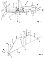
- the figure 1 shows schematically an embodiment of a projectile 1 implementing a navigation device and / or guidance and / or control according to the invention.
- the projectile 1 is equipped at its rear part with a deployable stabilizing stabilizer 2 and at its front part with four ducts 3, also deployable.
- a driving means or servomechanism 4 ensures the rotation of the various ducks 3 to achieve the steering of the projectile. This means is not shown in detail and it may include two or four geared motors (one per duck or one per driving plan).
- This projectile is for example a projectile fired by a cannon towards a goal.
- the fins of the empennage and the ducks are folded along the body of the projectile 1 or lodge in the body of the projectile. They deploy at the exit of the tube to perform their stabilization or steering functions.
- the pivoting of the ducks is controlled by an onboard computer 5.
- the projectile 1 also encloses a military head 6, for example a shaped charge, an explosive charge or one or more dispersible submunitions.
- the projectile 1 incorporates a triaxial magnetic sensor 7 (a single sensor or three magnetic probes or magneto-resistors distributed in three different directions of a measurement trihedron, for example three orthogonal probes between them and each preferably directed along one of the axes of the reference linked to the projectile GX p , GY p or GZ p ).
- a triaxial magnetic sensor 7 a single sensor or three magnetic probes or magneto-resistors distributed in three different directions of a measurement trihedron, for example three orthogonal probes between them and each preferably directed along one of the axes of the reference linked to the projectile GX p , GY p or GZ p ).
- This sensor makes it possible to measure the components of the terrestrial magnetic field H in a reference linked to the projectile 1.
- the magnetic sensor 7 is connected to the computer 5 which ensures the processing of measurements and their subsequent operation.
- the projectile 1 also includes an interface 8 for programming the computer. This interface is intended to cooperate with a programming means (not shown) attached to the weapon. It is connected to the calculator 5.
- the interface 8 will be constituted by an inductive loop disposed in the vicinity of the outer wall of the projectile body.
- the projectile 1 finally contains inertial means.
- These inertial means 9 comprise three accelerometers 10a, 10b, 10c respectively oriented along the axes of roll (GX p ), yaw (GY p ) and pitch (GZ p ) of the projectile 1.
- the inertial means 9 are intended in a conventional manner to allow in particular the implementation of control laws.
- the inertial means 9 are connected to the computer 5 which ensures the processing of the measurements made and their subsequent use for navigation, guidance and / or control of the projectile.
- figure 1 is an explanatory diagram that does not prejudge the locations and relative dimensions of the different elements.
- a single projectile rocket can incorporate the computer 5, the magnetic sensors 7 and the accelerometers 9.
- the projectile may also include a target detector 11 to allow a continuation of the latter when the projectile is in the terminal phase of its trajectory.
- the figure 2 shows an example of trajectory 12 that follows a projectile 1 according to the invention between its firing platform 13 and a target or objective B.
- This figure shows a reference centered at O (point where the platform or theoretical firing position 13 is located) and axes OX MB0 , OY MB0 and OZ MB0 .
- This reference is the land reference reference landmark which is chosen in this particular embodiment to implement the invention.
- the figure 3 shows as a reminder the three successive rotations which make it possible to pass from a fixed reference GX MB0 Y MB0 Z MB0 (OX mark MB0 Y MB0 Z MB0 centered in G after a vector translation OG) to the movable coordinate system GX p Y p Z p linked to the projectile.
- a first rotation of the X mark MB0 Y MB0 Z MB0 is performed around the Z axis MB0 , this rotation defines the angle ⁇ (or azimuth angle).
- the mark X 1 Y 1 Z 1 is then rotated around the axis Y 1 by an angle ⁇ (or attitude angle).
- the navigation of the projectile location of this one in the space
- the steps of guidance and control require to know at all times the angles of Euler ( ⁇ , ⁇ , ⁇ ) of the projectile in order to be able to locate the projectile by compared to its objective and thus be able to control the effects of the controls that are applied to the control surfaces.
- Gyrometers are expensive and fragile organs that do not withstand gunfire well.
- the invention proposes a method and a device that make it possible to dispense with gyrometers.
- This reference magnetic field will preferably be that measured at the firing position O. It will be measured for example by an axial tri-axial sensor linked to the firing platform 13 and having its detection axes oriented along the axes of the fixed landmark chosen (OX MB0 Y MB0 Z MB0 ).
- At least one azimuth angle value ⁇ n which can be considered as constant over at least part of the trajectory will be introduced into another memory or register of the computer.
- the projectiles fired at least have a part of their trajectory having a constant azimuth angle, it is their ballistic phase (T 1 on the figure 2 ).
- trajectory 12 For the non-ballistic phases of the trajectory of the projectile (piloted phases) it is also possible to decompose the theoretical trajectory curve 12 into several sections in which the azimuth angle can also be assumed to be constant.
- figure 2 shows a trajectory 12 comprising, after the ballistic phase T 1, six sections T 2 , T 3 , T 4 , T 5 , T 6 and T 7 on each of which the azimuth is substantially constant. It is of course possible to define a trajectory curve comprising a greater number of sections on each of which the azimuth is known.
- the trajectory profile 12 is known a priori. It is programmable before firing and can be correlated to an initialized clock during firing. This trajectory profile will thus be introduced in the form of a firing table in a memory of the projectile calculator. It is therefore also possible and in accordance with the invention to associate at a given moment a particular trajectory section having an azimuth angle ⁇ 1 , ⁇ 2 , ⁇ 3 , ⁇ 4 , ⁇ 5 , ⁇ 6 or ⁇ 7 .
- This azimuth angle will be used by the algorithm proposed by the invention to calculate the different angles of Euler for the portion of trajectory considered.
- measurements of the three components of the earth's magnetic field are finally made on the trajectory in the orthonormal frame linked to the projectile GX p Y p Z p .
- the different programmed values as well as the measured values are then used to calculate the roll and pitch angle of the projectile.
- the matrices making it possible to transform the magnetic field vector evaluated in the projectile marker into a vector evaluated in a fixed terrestrial reference frame.
- hp the magnetic field vector measured on board the projectile. This vector has components H px , H py and H pz in the reference linked to the projectile.
- H MB 0 the reference magnetic field vector. This vector has components H MB0x , H MB0y and H MB0z in the fixed terrestrial reference system.
- H p M ⁇ .M ⁇ .M ⁇ . H MB 0 expression which means that we pass from one vector to another by the product of three matrices of transformation and which can be written in a developed form:
- H px H py H pZ 1 0 0 0 cos ⁇ sin ⁇ 0 - sin ⁇ cos ⁇ cos ⁇ 0 sin ⁇ 0 1 0 - sin ⁇ 0 cos ⁇ cos ⁇ sin ⁇ 0 - sin ⁇ cos ⁇ 0 0 1 H MB 0 x H MB 0 there H MB 0 z
- H p M ⁇ .M ⁇ . H MB 0 expression in which M ⁇ represents a matrix which is the product of the two matrices relating to the angles ⁇ and ⁇ .
- the matrix M ⁇ has coefficients which will be noted later at ij .
- H px H py H pZ 1 0 0 0 cos ⁇ sin ⁇ 0 - sin ⁇ cos ⁇ at 11 at 12 at 13 at 21 at 22 at 23 at 31 at 32 at 33 H MB 0 x H MB 0 there H MB 0 z
- the invention proposes to remove the indeterminacy of these calculations by using at least one known and stored or programmed value before shooting the azimuth angle ⁇ .
- H px at 11 H MB0x + at 12 H MB0y + at 13 H MB0z .
- the attitude angle ⁇ is therefore immediately deduced from the values of the magnetic field (preprogrammed H MBO and measured H p ).
- This calculation may notably be performed on the ballistic trajectory portion of the projectile (T 1 ).
- H PY and H PZ are zero, it is a priori no longer possible to know the rolling position of the projectile with the previous calculation.
- Such a configuration appears when the projectile flies with its axis X P collinear Earth's magnetic field. To avoid such a problem, it suffices to shoot the projectile avoiding such a configuration.
- a suitable firing position O will be chosen and a shape of trajectory 12 leading to such collinearity will be avoided.
- the figure 4 shows an example of structural and functional organization of a device according to the invention.
- the computer 5 incorporates various calculation modules made in the form of algorithms stored in memories or registers.
- a first module 14 performs the calculation of the angles ⁇ , ⁇ and ⁇ from the programming data provided before firing by the programming means 8 or preprogrammed in the computer 5 and from the measurements of the components of the magnetic field made during the flight of the projectile by the triaxial magnetic sensor 7.
- the programming data incorporates a measurement of the three components of the reference magnetic field H MB0 in the fixed terrestrial reference centered on the firing position, a measurement which is stored in the memory 15.
- a second calculation module 18 realizes the derivation of the calculated angles and evaluates the components p, q and r of the instantaneous vector of rotation of the projectile.
- the guidance / control module 19 also uses the acceleration data of the projectile provided by the inertial means 9.
- This module controls the servomechanism 4 driving the control surfaces 3.
- This calculation is carried out in a specific azimuth evaluation module which uses the acceleration measurements provided by the inertial means 9 as well as an evaluation of the aerodynamic coefficient A of the projectile which is stored in memory (A is generally called the projectile incidence time constant).
- This azimuth calculation is made from a calculation of the angles made by the projection of the speed vector V of the shell in the planes GX MB0 Y MBO and GX MB0 Z MB0 of the fixed reference with respect to the axes of this reference.
- the figure 5a thus shows the skid plane GX MB0 Y MBO in which the projection V Y of the velocity vector of the shell makes an angle P (skid angle) with the axis GX P of the shell and an angle ⁇ Y (aerodynamic azimuth ) with GX axis MB0 .
- the azimuth angle ⁇ is also shown in this figure.
- the figure 5b shows the plane of incidence GX MB0 Z MBO in which the projection V Z of the velocity vector of the shell makes an angle ⁇ (angle of incidence) with the axis GX P of the shell and an angle ⁇ Z (slope aerodynamic) with GX axis MB0 .
- the attitude angle ⁇ is also represented in this figure.
- the inertial means 9 make it possible to determine at a time t the value of the components of the acceleration vector along the axes GX P , GY P and GZ P of the projectile.
- ⁇ n f ( ⁇ n , H n , H MB0 , ⁇ nT , ⁇ nT , ⁇ nT ) from which we deduce: ⁇ n and ⁇ n as well as the angles p n , q n and r n .
- This embodiment makes it possible to improve (for a duck-head projectile) the performances of the navigation method according to the invention by making it possible to overcome the majority of the errors related to magnetic and aerodynamic disturbances on the theoretical location of the azimuth zones. constant.
- the differences observed during disturbed trajectories are in all cases less than 2 ° to 3 ° for each angle, which is sufficient for a projectile having a short range trajectory (less than 10 km).
- deviations may be less than the degree if the magnetic disturbances are corrected and the ballistic disturbances are taken into account (for example by introducing a bias during firing).
- This sound is related to the fact that the angle is estimated from a tangent arc function whose result is between - ⁇ and + ⁇ (or between 0 and 2 ⁇ with a different choice of arc tangent function) and has a discontinuity the transition to the value ⁇ . This discontinuity disrupts the calculation of the derivative.
- This linearization is based on a priori knowledge of the amplitude of the jump of the roll angle which is 2 ⁇ each time.
- the figure 6 thus shows the value of the roll angle ⁇ calculated ("sawtooth" curve 21) and the linearized value (curve 22).
- the tangent arc function used will be corrected beforehand so as to give the value of the calculated arc a value between 0 and 2 ⁇ .
- the magnetic field measured by the triaxial magnetic sensor 7 is likely to be disturbed by the electromagnetic environment of the projectile 1.
- the most disturbing elements are the motors of the servomechanism 4 because they implement permanent magnets.
- the body of the projectile itself is also a source of disturbance of the measurements. Indeed its metallic mass induces a local deformation of the lines of the Earth's magnetic field.
- a similar method can be applied to correct the measurements along the transverse axes GY P and GZ P.
- the correction factor can be calculated only when the projectile will turn a little on itself (speed of at least 0.25 revolutions / second), which will occur a few seconds after the shot but still during the ballistic phase.
- the correction along the transverse axes is based on the fact that the measurements H PY and H PZ must be in theory sinusoidal and in phase quadrature. This means that, in theory, if a measure along the G YP direction is maximum, it must be zero on the GZ P path. Moreover, the modulus of the field remains constant during the flight (and normed to 1 in the calculations).
- the magnetic field H MB0 measured at the level of the firing platform 13 has been considered as reference value. This field is considered constant over the entire trajectory provided for the projectile.
- the invention will then simplify the guidance / control of a missile or a rocket by removing the gyrometers.
Landscapes
- Engineering & Computer Science (AREA)
- Aviation & Aerospace Engineering (AREA)
- Radar, Positioning & Navigation (AREA)
- Remote Sensing (AREA)
- Physics & Mathematics (AREA)
- General Physics & Mathematics (AREA)
- Automation & Control Theory (AREA)
- Aiming, Guidance, Guns With A Light Source, Armor, Camouflage, And Targets (AREA)
Claims (15)
- Verfahren, welches es ermöglicht, die Navigation und/oder die Führung und/oder die Steuerung eines Projektils (1) auf ein Ziel (B) zu gewährleisten, wobei bei dem Verfahren eine Berechnung sämtlicher oder eines Teils der Eulerschen Winkel (ψ,θ,ϕ) des Projektils verwendet wird, um die Bestimmung der Fluglage und/oder der Lokalisierung des Projektils (1) in einem terrestrischen Koordinatensystem zu ermöglichen, wobei das Verfahren dadurch gekennzeichnet ist, dass:vor dem Abschuss in einen Speicher oder ein Register eines Rechners (5) des Projektils (1) mindestens eine Wert der drei Komponenten (HMB0x,HMB0y,HMB0z) eines Bezugsmagnetfeldes in einem festen, direkten und orthonormierten terrestrischen Koordinatensystem eingetragen wird, wobei das Koordinatensystem auf die Schußposition O zentriert ist und eine horizontale Achse und eine vertikale Achse aufweist, wobei die Orientierung des Koordinatensystems in Bezug auf die Richtung des Ziels (B) bekannt und festgelegt oder programmiert ist,mindestens ein Azimut-Winkelwert (ψ) durch Konstruktion festgelegt oder vor dem Abschuss in einem anderen Speicher oder Register des Rechners (5) programmiert wird,auf der Flugbahn mindestens eine Messung der drei Komponenten (Hpx,Hpy,Hpz) des Magnetfeldes in einem orthonormierten, an das Projektil (1) gebundenen Koordinatensystem durchgeführt wird,auf der Flugbahn der Rollwinkel ϕ und/oder der Neigungswinkel θ ausgehend von den gemessenen Magnetfeld-Werten des oder der Werte des Referenzfeldes und des gespeicherten Azimut-Winkelwerts für den betreffenden Teil der Flugbahn berechnet wird.
- Verfahren zur Navigation und/oder Führung und/oder Steuerung nach Anspruch 1, dadurch gekennzeichnet, dass das feste terrestrische Koordinatensystem so ausgewählt wird, dass es auf die Schußposition 0 zentriert ist und eine horizontale Achse OXMB0 aufweist, welche in Richtung des Ziels (B) orientiert ist.
- Verfahren zur Navigation und/oder Führung und/oder Steuerung nach einem der Ansprüche 1 oder 2, dadurch gekennzeichnet, dass der Wert des Bezugsmagnetfeldes (HMB0x,HMB0y,HMB0z) vor dem Abschuss im Bereich der Schußposition O gemessen und im Speicher eingetragen wird, wobei die Berechnung des oder der Winkel ausgehend von dieser Messung durchgeführt wird.
- Verfahren zur Navigation und/oder Führung und/oder Steuerung nach Anspruch 3, dadurch gekennzeichnet, dass der Neigungswinkel θ ausgehend von mindestens einer Messung der Komponente HPX des Magnetfeldes gemäß der Achse XP des Projektils durch die folgende Formel berechnet wird:

b und c Funktionskoeffizienten der Komponenten HMB0X, HMB0Y und HMB0Z des Bezugsmagnetfeldes in dem festen, terrestrischen Koordinatensystem sind, die beispielsweise vor dem Abschuss programmiert werden, und ψn ein Azimutwinkelwert ist, welcher über den betreffenden Teil (Tn) der Flugbahn (12) bekannt ist. - Verfahren zur Navigation und/oder Führung und/oder Steuerung nach Anspruch 4, dadurch gekennzeichnet, dass der Rollwinkel ϕ ausgehend von der Berechnung des Neigungswinkels unter Verwendung von mindestens einer Messung der Komponenten HPY und HPZ des Magnetfeldes gemäß den Achsen YP und ZP des Projektils durch die folgende Formel berechnet wird:

d und e Funktionskoeffizienten der Komponenten HMB0X, HMB0Y und HMB0Z des Bezugsmagnetfeldes in dem festen, terrestrischen Koordinatensystem, die beispielsweise vor dem Abschuss programmiert werden, und Koeffizienten einer teilweisen Übergangsmatrix M(θ,ψ) von dem festen, terrestrischen Koordinatensystem zu dem an das Projektil (1) gebundenen Koordinatensystem sind, und wobei nur die Azimutwinkel ψ und Neigungswinkel θ berücksichtigt werden. - Verfahren zur Navigation und/oder Führung und/oder Steuerung nach Anspruch 5, dadurch gekennzeichnet, dass nach Berechnung des Rollwinkels ϕ mit einer Linearisierung dessen Wertes fortgefahren wird.
- Verfahren zur Navigation und/oder Führung und/oder Steuerung nach einem der Ansprüche 4 bis 6, dadurch gekennzeichnet, dass während einer ballistischen Flugphase der Azimutwinkel ψn = ψ1 im Speicher festgelegt oder vor dem Abschuss programmiert wird und dem Azimutwinkel entspricht, welcher dem Projektil (1) beim Abschuss verliehen wird.
- Verfahren zur Navigation und/oder Führung und/oder Steuerung nach einem der Ansprüche 4 bis 6, dadurch gekennzeichnet, dass während einer gesteuerten Flugphase der für den betreffenden Teil (Tn) der Flugbahn (12) angenommene Azimutwinkel ψn ein Wert ist, welcher vor dem Abschuss gespeichert wurde und in eine Schusstabelle (16) eingefügt wird, welche in Zusammenhang mit einer ab dem Zeitpunkt des Abschusses laufenden Uhr (17) ausgelesen wird.
- Verfahren zur Navigation und/oder Führung und/oder Steuerung nach einem der Ansprüche 4 bis 6, dadurch gekennzeichnet, dass während einer gesteuerten Flugphase der für den betreffenden Teil der Flugbahn angenommene Azimutwinkel ψn ein Wert ist, welcher auf der Flugbahn ausgehend von aerodynamischen Koeffizienten des Projektils, mindestens einer Messung der Beschleunigung und mindestens einem im Speicher festgelegten oder programmierten Wert eines Azimutwinkels berechnet wird.
- Verfahren zur Navigation und/oder Führung und/oder Steuerung nach einem der Ansprüche 1 bis 9, dadurch gekennzeichnet, dass die Komponenten des augenblicklichen Drehvektors
Ω des Projektils (1)in einem an das Projektil gebundenen Koordinatensystem ausgehend von den Werten der berechneten Eulerschen Winkel sowie ihrer zeitlichen Ableitungen ausgewertet werden. - Verfahren zur Navigation und/oder Führung und/öder Steuerung nach einem der Ansprüche 1 bis 10, dadurch gekennzeichnet, dass, um die Magnetfeldmessungen von einem Teil der durch die Umgebung der Sensoren (7) beigetragenen Störungen zu bereinigen, wird mindestens eine Korrektur während einer Phase durchgeführt, welche einen stabilen Azimutwinkel ψ aufweist, wobei die Korrektur eine Messung eines Unterschieds zwischen dem theoretischen Magnetfeld und dem gemessenen Magnetfeld aufweist.
- Verfahren zur Navigation und/oder Führung und/oder Steuerung nach Anspruch 11, dadurch gekennzeichnet, dass, um die Korrektur durchzuführen, mindestens ein programmierter öder gespeicherter Wert des Azimutwinkels ψ und mindestens ein programmierter oder gespeicherter Wert des Neigungswinkels θ verwendet wird.
- Vorrichtung, welche es ermöglicht, die Navigation und/oder die Führung und/oder die Steuerung eines Projektils (1) zu gewährleisten, wobei die Vorrichtung mindestens einen Magnetsensor (7) umfasst, welcher die Messung der drei Komponenten (Hpx,Hpy,Hpz) des Magnetfeldes in einem orthonormierten, an das Projektil (1) gebundenen Koordinatensystem gewährleistet, wobei die Vorrichtung das Verfahren nach einem der vorhergehenden Ansprüche einsetzt und dadurch gekennzeichnet ist, dass sie mindestens einen Rechner (5) aufweist, welcher einen Rechenalgorithmus (14) enthält zur Berechnung der Eulerschen Winkel, wobei der Rechner mit Speichermitteln (15) verknüpft ist, welche an Mittel (8) gekoppelt sind, welche vor Abschuss Programmdaten von den gennannten Speichern liefern, wobei die Speichermittel dafür vorgesehen sind, mindestens einen Wert der drei Komponenten eines Bezugsmagnetfeldes (HMB0x,HMB0y,HMB0z) in einem festen terrestrischen Koordinatensystem zu speichern, wobei diese Programmdaten von dem Rechner (5) mit den Messungen des Magnetfeldes auf der Flugbahn verwendet werden, um für mindestens einen Teil (Tn) der Flugbahn (12) mit einem im Wesentlichen konstanten Azimutwinkel (ψn) sämtliche oder einen Teil der Eulerschen Winkel zu bestimmen und es zu ermöglichen, so die Navigation und/oder Führung und/oder die Steuerung des Projektils (1) zu gewährleisten.
- Vorrichtung nach Anspruch 13, dadurch gekennzeichnet, dass das Projektil Trägheitsmittel (9) aufweist.
- Vorrichtung nach einem der Ansprüche 13 oder 14, dadurch gekennzeichnet, dass der Rechner (5) Mittel (23) enthält, welche es ermöglichen, die Messungen des Magnetfeldes von einem Teil der durch die Umgebung der Sensoren beigetragenen Störungen zu bereinigen.
Applications Claiming Priority (1)
| Application Number | Priority Date | Filing Date | Title |
|---|---|---|---|
| FR0513205A FR2895099B1 (fr) | 2005-12-19 | 2005-12-19 | Procede permettant d'assurer la navigation et/ou le guidage et/ou le pilotage d'un projectile vers un objectif et dispositif mettant en oeuvre un tel procede. |
Publications (2)
| Publication Number | Publication Date |
|---|---|
| EP1798622A1 EP1798622A1 (de) | 2007-06-20 |
| EP1798622B1 true EP1798622B1 (de) | 2018-05-30 |
Family
ID=37199270
Family Applications (1)
| Application Number | Title | Priority Date | Filing Date |
|---|---|---|---|
| EP06291978.2A Active EP1798622B1 (de) | 2005-12-19 | 2006-12-19 | Verfahren, das ein Absichern der Navigation und/oder der Lenkung und/oder der Steuerung eines Projektils zu einem Ziel ermöglicht, und Vorrichtung, die ein solches Verfahren einsetzt |
Country Status (4)
| Country | Link |
|---|---|
| EP (1) | EP1798622B1 (de) |
| ES (1) | ES2677272T3 (de) |
| FR (1) | FR2895099B1 (de) |
| IL (1) | IL180183A (de) |
Families Citing this family (5)
| Publication number | Priority date | Publication date | Assignee | Title |
|---|---|---|---|---|
| CN104089616A (zh) * | 2014-07-31 | 2014-10-08 | 四川阿泰因机器人智能装备有限公司 | 移动机器人定位系统 |
| CN109579617B (zh) * | 2018-12-21 | 2020-10-16 | 上海机电工程研究所 | 鸭式气动布局导弹的滚转控制方法、系统及介质 |
| CN112429265A (zh) * | 2020-10-27 | 2021-03-02 | 西安羚控电子科技有限公司 | 一种炮射无人机炮射起飞控制方法 |
| FR3116330A1 (fr) | 2020-11-19 | 2022-05-20 | Thales | Système de guidage d'une munition |
| CN112278891B (zh) * | 2020-12-29 | 2021-04-02 | 南京景曜智能科技有限公司 | 一种车厢内部姿态检测方法 |
Family Cites Families (4)
| Publication number | Priority date | Publication date | Assignee | Title |
|---|---|---|---|---|
| DE1578299B2 (de) * | 1967-10-14 | 1976-03-11 | Licenti a Patent-Verwaltung s-GmbH, 6000 Frankfurt | Verfahren zur treffpunktvorverlegung fuer passiv ortende in der eigenlenkphase mittels proportionalnavigation gelenkte geschosse |
| US5253823A (en) * | 1983-10-07 | 1993-10-19 | The Secretary Of State For Defence In Her Britannic Majesty's Government Of The United Kingdom Of Great Britain And Northern Ireland | Guidance processor |
| US6573486B1 (en) * | 2002-02-22 | 2003-06-03 | Northrop Grumman Corporation | Projectile guidance with accelerometers and a GPS receiver |
| US7032857B2 (en) * | 2003-08-19 | 2006-04-25 | Cuong Tu Hua | Multi-sensor guidance system for extreme force launch shock applications |
-
2005
- 2005-12-19 FR FR0513205A patent/FR2895099B1/fr not_active Expired - Fee Related
-
2006
- 2006-12-19 EP EP06291978.2A patent/EP1798622B1/de active Active
- 2006-12-19 ES ES06291978.2T patent/ES2677272T3/es active Active
- 2006-12-19 IL IL180183A patent/IL180183A/en not_active IP Right Cessation
Non-Patent Citations (1)
| Title |
|---|
| None * |
Also Published As
| Publication number | Publication date |
|---|---|
| FR2895099A1 (fr) | 2007-06-22 |
| EP1798622A1 (de) | 2007-06-20 |
| FR2895099B1 (fr) | 2008-01-25 |
| ES2677272T3 (es) | 2018-07-31 |
| IL180183A0 (en) | 2007-06-03 |
| IL180183A (en) | 2012-08-30 |
Similar Documents
| Publication | Publication Date | Title |
|---|---|---|
| EP1617165A1 (de) | Verfahren zur Lenkung und/oder Führung eines Geschosses und Vorrichtung zur Lenkung und/oder Führung mit Mitteln zur Durchführung dieses Verfahrens | |
| EP3111166B1 (de) | Trägheitsnavigationssystem | |
| EP3260815B1 (de) | Trägheitsnavigationssystem | |
| US11112422B2 (en) | Inertial navigation system | |
| EP2009387B1 (de) | Steuerverfahren zur Auslösung eines Angriffsmoduls und Vorrichtung zur Umsetzung eines solchen Verfahrens | |
| EP2048475B1 (de) | Verfahren zur Bestimmung der Lage, Position und Geschwindigkeit eines beweglichen Geräts | |
| EP1798622B1 (de) | Verfahren, das ein Absichern der Navigation und/oder der Lenkung und/oder der Steuerung eines Projektils zu einem Ziel ermöglicht, und Vorrichtung, die ein solches Verfahren einsetzt | |
| EP2169508B1 (de) | Geschosssteuerungssystem | |
| EP1480000B1 (de) | Verfahren zur Lenkung der Flugbahn eines drehenden Geschosses | |
| US8047070B2 (en) | Fast response projectile roll estimator | |
| US10907936B2 (en) | State estimation | |
| EP1840692B1 (de) | Verfahren zur Steuerung und/oder Lenkung eines Projektils und Vorrichtung zum Steuern und/oder Lenken mit Hilfe dieses Verfahrens | |
| EP3543651B1 (de) | Echtzeitkompensierung von trägheitsgyroskopen | |
| EP1422587A1 (de) | Verfahren zur Herstellung eines Steuerungsbefehles für ein die Steuerung eines drehenden Geschosses ermöglichendes Gerät | |
| EP3109722B1 (de) | Verfahren zum vermeiden einer verbotenen zone durch einen satelliten | |
| FR2829593A1 (fr) | Procede de guidage d'un engin, notamment d'une munition | |
| EP1785688B1 (de) | Verfahren und Vorrichtung um die Rotationsgeschwindigkeit der Geschoßziellinie zu bestimmen und Lenkvorrichtung eines Geschoßes, insbesondere von Munition | |
| de Celis et al. | Adaptive Navigation, Guidance and Control Techniques Applied to Ballistic Projectiles and Rockets | |
| Steffes et al. | Alignment between IMU and star tracker using the night sky and an on-board navigation system |
Legal Events
| Date | Code | Title | Description |
|---|---|---|---|
| PUAI | Public reference made under article 153(3) epc to a published international application that has entered the european phase |
Free format text: ORIGINAL CODE: 0009012 |
|
| AK | Designated contracting states |
Kind code of ref document: A1 Designated state(s): AT BE BG CH CY CZ DE DK EE ES FI FR GB GR HU IE IS IT LI LT LU LV MC NL PL PT RO SE SI SK TR |
|
| AX | Request for extension of the european patent |
Extension state: AL BA HR MK YU |
|
| 17P | Request for examination filed |
Effective date: 20071206 |
|
| 17Q | First examination report despatched |
Effective date: 20080121 |
|
| AKX | Designation fees paid |
Designated state(s): AT BE BG CH CY CZ DE DK EE ES FI FR GB GR HU IE IS IT LI LT LU LV MC NL PL PT RO SE SI SK TR |
|
| GRAP | Despatch of communication of intention to grant a patent |
Free format text: ORIGINAL CODE: EPIDOSNIGR1 |
|
| INTG | Intention to grant announced |
Effective date: 20171221 |
|
| GRAS | Grant fee paid |
Free format text: ORIGINAL CODE: EPIDOSNIGR3 |
|
| GRAA | (expected) grant |
Free format text: ORIGINAL CODE: 0009210 |
|
| AK | Designated contracting states |
Kind code of ref document: B1 Designated state(s): AT BE BG CH CY CZ DE DK EE ES FI FR GB GR HU IE IS IT LI LT LU LV MC NL PL PT RO SE SI SK TR |
|
| REG | Reference to a national code |
Ref country code: GB Ref legal event code: FG4D Free format text: NOT ENGLISH |
|
| REG | Reference to a national code |
Ref country code: CH Ref legal event code: EP |
|
| REG | Reference to a national code |
Ref country code: AT Ref legal event code: REF Ref document number: 1004249 Country of ref document: AT Kind code of ref document: T Effective date: 20180615 |
|
| REG | Reference to a national code |
Ref country code: DE Ref legal event code: R096 Ref document number: 602006055499 Country of ref document: DE |
|
| REG | Reference to a national code |
Ref country code: IE Ref legal event code: FG4D Free format text: LANGUAGE OF EP DOCUMENT: FRENCH |
|
| REG | Reference to a national code |
Ref country code: ES Ref legal event code: FG2A Ref document number: 2677272 Country of ref document: ES Kind code of ref document: T3 Effective date: 20180731 |
|
| REG | Reference to a national code |
Ref country code: SE Ref legal event code: TRGR |
|
| REG | Reference to a national code |
Ref country code: NL Ref legal event code: MP Effective date: 20180530 |
|
| REG | Reference to a national code |
Ref country code: LT Ref legal event code: MG4D |
|
| PG25 | Lapsed in a contracting state [announced via postgrant information from national office to epo] |
Ref country code: LT Free format text: LAPSE BECAUSE OF FAILURE TO SUBMIT A TRANSLATION OF THE DESCRIPTION OR TO PAY THE FEE WITHIN THE PRESCRIBED TIME-LIMIT Effective date: 20180530 Ref country code: FI Free format text: LAPSE BECAUSE OF FAILURE TO SUBMIT A TRANSLATION OF THE DESCRIPTION OR TO PAY THE FEE WITHIN THE PRESCRIBED TIME-LIMIT Effective date: 20180530 Ref country code: BG Free format text: LAPSE BECAUSE OF FAILURE TO SUBMIT A TRANSLATION OF THE DESCRIPTION OR TO PAY THE FEE WITHIN THE PRESCRIBED TIME-LIMIT Effective date: 20180830 Ref country code: CY Free format text: LAPSE BECAUSE OF FAILURE TO SUBMIT A TRANSLATION OF THE DESCRIPTION OR TO PAY THE FEE WITHIN THE PRESCRIBED TIME-LIMIT Effective date: 20180530 |
|
| PG25 | Lapsed in a contracting state [announced via postgrant information from national office to epo] |
Ref country code: GR Free format text: LAPSE BECAUSE OF FAILURE TO SUBMIT A TRANSLATION OF THE DESCRIPTION OR TO PAY THE FEE WITHIN THE PRESCRIBED TIME-LIMIT Effective date: 20180831 Ref country code: LV Free format text: LAPSE BECAUSE OF FAILURE TO SUBMIT A TRANSLATION OF THE DESCRIPTION OR TO PAY THE FEE WITHIN THE PRESCRIBED TIME-LIMIT Effective date: 20180530 |
|
| REG | Reference to a national code |
Ref country code: AT Ref legal event code: MK05 Ref document number: 1004249 Country of ref document: AT Kind code of ref document: T Effective date: 20180530 |
|
| PG25 | Lapsed in a contracting state [announced via postgrant information from national office to epo] |
Ref country code: NL Free format text: LAPSE BECAUSE OF FAILURE TO SUBMIT A TRANSLATION OF THE DESCRIPTION OR TO PAY THE FEE WITHIN THE PRESCRIBED TIME-LIMIT Effective date: 20180530 |
|
| PG25 | Lapsed in a contracting state [announced via postgrant information from national office to epo] |
Ref country code: CZ Free format text: LAPSE BECAUSE OF FAILURE TO SUBMIT A TRANSLATION OF THE DESCRIPTION OR TO PAY THE FEE WITHIN THE PRESCRIBED TIME-LIMIT Effective date: 20180530 Ref country code: AT Free format text: LAPSE BECAUSE OF FAILURE TO SUBMIT A TRANSLATION OF THE DESCRIPTION OR TO PAY THE FEE WITHIN THE PRESCRIBED TIME-LIMIT Effective date: 20180530 Ref country code: DK Free format text: LAPSE BECAUSE OF FAILURE TO SUBMIT A TRANSLATION OF THE DESCRIPTION OR TO PAY THE FEE WITHIN THE PRESCRIBED TIME-LIMIT Effective date: 20180530 Ref country code: EE Free format text: LAPSE BECAUSE OF FAILURE TO SUBMIT A TRANSLATION OF THE DESCRIPTION OR TO PAY THE FEE WITHIN THE PRESCRIBED TIME-LIMIT Effective date: 20180530 Ref country code: SK Free format text: LAPSE BECAUSE OF FAILURE TO SUBMIT A TRANSLATION OF THE DESCRIPTION OR TO PAY THE FEE WITHIN THE PRESCRIBED TIME-LIMIT Effective date: 20180530 Ref country code: RO Free format text: LAPSE BECAUSE OF FAILURE TO SUBMIT A TRANSLATION OF THE DESCRIPTION OR TO PAY THE FEE WITHIN THE PRESCRIBED TIME-LIMIT Effective date: 20180530 Ref country code: PL Free format text: LAPSE BECAUSE OF FAILURE TO SUBMIT A TRANSLATION OF THE DESCRIPTION OR TO PAY THE FEE WITHIN THE PRESCRIBED TIME-LIMIT Effective date: 20180530 |
|
| REG | Reference to a national code |
Ref country code: DE Ref legal event code: R097 Ref document number: 602006055499 Country of ref document: DE |
|
| PLBE | No opposition filed within time limit |
Free format text: ORIGINAL CODE: 0009261 |
|
| STAA | Information on the status of an ep patent application or granted ep patent |
Free format text: STATUS: NO OPPOSITION FILED WITHIN TIME LIMIT |
|
| 26N | No opposition filed |
Effective date: 20190301 |
|
| PG25 | Lapsed in a contracting state [announced via postgrant information from national office to epo] |
Ref country code: SI Free format text: LAPSE BECAUSE OF FAILURE TO SUBMIT A TRANSLATION OF THE DESCRIPTION OR TO PAY THE FEE WITHIN THE PRESCRIBED TIME-LIMIT Effective date: 20180530 |
|
| REG | Reference to a national code |
Ref country code: CH Ref legal event code: PL |
|
| PG25 | Lapsed in a contracting state [announced via postgrant information from national office to epo] |
Ref country code: MC Free format text: LAPSE BECAUSE OF FAILURE TO SUBMIT A TRANSLATION OF THE DESCRIPTION OR TO PAY THE FEE WITHIN THE PRESCRIBED TIME-LIMIT Effective date: 20180530 Ref country code: LU Free format text: LAPSE BECAUSE OF NON-PAYMENT OF DUE FEES Effective date: 20181219 |
|
| REG | Reference to a national code |
Ref country code: IE Ref legal event code: MM4A |
|
| PG25 | Lapsed in a contracting state [announced via postgrant information from national office to epo] |
Ref country code: IE Free format text: LAPSE BECAUSE OF NON-PAYMENT OF DUE FEES Effective date: 20181219 |
|
| PG25 | Lapsed in a contracting state [announced via postgrant information from national office to epo] |
Ref country code: CH Free format text: LAPSE BECAUSE OF NON-PAYMENT OF DUE FEES Effective date: 20181231 Ref country code: LI Free format text: LAPSE BECAUSE OF NON-PAYMENT OF DUE FEES Effective date: 20181231 |
|
| PG25 | Lapsed in a contracting state [announced via postgrant information from national office to epo] |
Ref country code: TR Free format text: LAPSE BECAUSE OF FAILURE TO SUBMIT A TRANSLATION OF THE DESCRIPTION OR TO PAY THE FEE WITHIN THE PRESCRIBED TIME-LIMIT Effective date: 20180530 |
|
| PG25 | Lapsed in a contracting state [announced via postgrant information from national office to epo] |
Ref country code: PT Free format text: LAPSE BECAUSE OF FAILURE TO SUBMIT A TRANSLATION OF THE DESCRIPTION OR TO PAY THE FEE WITHIN THE PRESCRIBED TIME-LIMIT Effective date: 20180530 |
|
| PG25 | Lapsed in a contracting state [announced via postgrant information from national office to epo] |
Ref country code: HU Free format text: LAPSE BECAUSE OF FAILURE TO SUBMIT A TRANSLATION OF THE DESCRIPTION OR TO PAY THE FEE WITHIN THE PRESCRIBED TIME-LIMIT; INVALID AB INITIO Effective date: 20061219 |
|
| PG25 | Lapsed in a contracting state [announced via postgrant information from national office to epo] |
Ref country code: IS Free format text: LAPSE BECAUSE OF FAILURE TO SUBMIT A TRANSLATION OF THE DESCRIPTION OR TO PAY THE FEE WITHIN THE PRESCRIBED TIME-LIMIT Effective date: 20180930 |
|
| PGFP | Annual fee paid to national office [announced via postgrant information from national office to epo] |
Ref country code: IT Payment date: 20221122 Year of fee payment: 17 |
|
| REG | Reference to a national code |
Ref country code: DE Ref legal event code: R079 Ref document number: 602006055499 Country of ref document: DE Free format text: PREVIOUS MAIN CLASS: G05D0001120000 Ipc: G05D0001683000 |
|
| PGFP | Annual fee paid to national office [announced via postgrant information from national office to epo] |
Ref country code: GB Payment date: 20231121 Year of fee payment: 18 |
|
| PGFP | Annual fee paid to national office [announced via postgrant information from national office to epo] |
Ref country code: SE Payment date: 20231121 Year of fee payment: 18 Ref country code: FR Payment date: 20231122 Year of fee payment: 18 Ref country code: DE Payment date: 20231121 Year of fee payment: 18 |
|
| PGFP | Annual fee paid to national office [announced via postgrant information from national office to epo] |
Ref country code: BE Payment date: 20231121 Year of fee payment: 18 |
|
| PGFP | Annual fee paid to national office [announced via postgrant information from national office to epo] |
Ref country code: ES Payment date: 20240102 Year of fee payment: 18 |