EP1798622B1 - Method providing the navigation and/or guidance of a projectile towards a target and device implementing said method - Google Patents
Method providing the navigation and/or guidance of a projectile towards a target and device implementing said method Download PDFInfo
- Publication number
- EP1798622B1 EP1798622B1 EP06291978.2A EP06291978A EP1798622B1 EP 1798622 B1 EP1798622 B1 EP 1798622B1 EP 06291978 A EP06291978 A EP 06291978A EP 1798622 B1 EP1798622 B1 EP 1798622B1
- Authority
- EP
- European Patent Office
- Prior art keywords
- projectile
- magnetic field
- reference frame
- guidance
- value
- Prior art date
- Legal status (The legal status is an assumption and is not a legal conclusion. Google has not performed a legal analysis and makes no representation as to the accuracy of the status listed.)
- Active
Links
- 238000000034 method Methods 0.000 title claims description 27
- 238000010304 firing Methods 0.000 claims description 50
- 238000005259 measurement Methods 0.000 claims description 39
- 238000004364 calculation method Methods 0.000 claims description 30
- 230000015654 memory Effects 0.000 claims description 20
- 238000012937 correction Methods 0.000 claims description 15
- 230000001133 acceleration Effects 0.000 claims description 12
- 230000006870 function Effects 0.000 claims description 10
- 238000004422 calculation algorithm Methods 0.000 claims description 9
- 239000011159 matrix material Substances 0.000 claims description 9
- 238000011156 evaluation Methods 0.000 description 6
- 239000003550 marker Substances 0.000 description 6
- 241000272517 Anseriformes Species 0.000 description 5
- 230000014509 gene expression Effects 0.000 description 4
- 238000010276 construction Methods 0.000 description 3
- 238000010586 diagram Methods 0.000 description 3
- 238000012545 processing Methods 0.000 description 3
- 238000012546 transfer Methods 0.000 description 3
- 241000272525 Anas platyrhynchos Species 0.000 description 2
- 230000000875 corresponding effect Effects 0.000 description 2
- 238000001514 detection method Methods 0.000 description 2
- 230000001939 inductive effect Effects 0.000 description 2
- 230000007246 mechanism Effects 0.000 description 2
- 239000000523 sample Substances 0.000 description 2
- 230000009466 transformation Effects 0.000 description 2
- 241000287107 Passer Species 0.000 description 1
- 230000000052 comparative effect Effects 0.000 description 1
- 230000002596 correlated effect Effects 0.000 description 1
- 238000000354 decomposition reaction Methods 0.000 description 1
- 238000009795 derivation Methods 0.000 description 1
- 230000000694 effects Effects 0.000 description 1
- 239000002360 explosive Substances 0.000 description 1
- 230000010354 integration Effects 0.000 description 1
- 210000000056 organ Anatomy 0.000 description 1
- 230000008520 organization Effects 0.000 description 1
- 238000005096 rolling process Methods 0.000 description 1
- 238000005070 sampling Methods 0.000 description 1
- 238000004088 simulation Methods 0.000 description 1
- 230000006641 stabilisation Effects 0.000 description 1
- 238000011105 stabilization Methods 0.000 description 1
- 239000003381 stabilizer Substances 0.000 description 1
- 230000000087 stabilizing effect Effects 0.000 description 1
- 238000012360 testing method Methods 0.000 description 1
- 230000007704 transition Effects 0.000 description 1
- 238000013519 translation Methods 0.000 description 1
Images


Classifications
-
- G—PHYSICS
- G05—CONTROLLING; REGULATING
- G05D—SYSTEMS FOR CONTROLLING OR REGULATING NON-ELECTRIC VARIABLES
- G05D1/00—Control of position, course or altitude of land, water, air, or space vehicles, e.g. automatic pilot
- G05D1/12—Target-seeking control
Definitions
- the technical field of the invention is that of methods and devices for navigating and / or guiding and / or steering a projectile towards a target.
- the document US2005 / 0040280 describes a multi-detector guidance device for projectiles having to undergo very high accelerations.
- the purpose of this patent is to replace fragile inertial units by means that can withstand fire.
- This patent does not describe an implementation of magnetic detectors for determining the roll angle and / or the attitude angle of the projectile using the values of the magnetic field in the projectile reference, a field value reference and the stored azimuth value.
- the magnetic sensors are associated with other detectors and the mode of data processing is not specified.
- the patent US 6573486 describes a guide means for a projectile not using a gyrometer but associating a GPS sensor and accelerometers. No magnetic detector is implemented in this patent as proposed by the invention.
- the known projectiles are guided towards their target by a guiding device which prepares the acceleration correction commands to be applied to the projectile to direct it to the target.
- correction orders are then used by a control device that develops the commands to be applied to the steering members to ensure the desired correction.
- GPS Global Positioning System
- Such a device allows the projectile to locate on trajectory.
- the projectile receives before shooting a program that gives it the coordinates of its target.
- This inertial measurement unit comprises accelerometers and gyroscopes, which provide (in a frame linked to the projectile) the components of the instantaneous vector of rotation and the non-gravitational acceleration to which the projectile is subjected.
- This inertial measurement unit is used to know the orientation of the projectile and in particular to determine the angles of Euler allowing to pass from a reference linked to the projectile to the terrestrial fixed reference.
- the fixed terrestrial reference will be chosen centered on the firing position and having a horizontal axis oriented in the direction of the objective.
- the value of the reference magnetic field can be measured before firing at the firing position and introduced in memory, the calculation of the angle or angles being then made from this measurement.
- the azimuth angle ⁇ n adopted for the part of trajectory considered will be a value that will be memorized before firing and incorporated in a firing table that will be read in relation with a clock counted from the instant of fire.
- the azimuth angle ⁇ n adopted for the part of trajectory considered will be a value which will be calculated on trajectory from the aerodynamic coefficients of the projectile, at least one measurement of the acceleration and at least one value fixed in memory or programmed by an azimuth angle.
- At least one programmed or memorized value of the azimuth angle and at least one programmed or memorized value of the attitude angle can be used.
- the invention also relates to a device for providing navigation and / or guidance and / or control of a projectile, device comprising at least one magnetic sensor for measuring the three components of the magnetic field in an orthonormal frame related to the projectile, device implementing the method according to the invention and characterized in that it comprises at least one computer incorporating an algorithm for calculating Euler angles, calculator associated with memory means coupled to means providing before shooting programming data of said memories, the memory means being intended to store at least one value of the three components of a reference magnetic field in a fixed terrestrial reference, these programming data being used by the computer with the measurements of the magnetic field on trajectory for determining, for at least a portion of trajectory having a substantially consistent azimuth angle so, all or part of Euler angles and allow to ensure the navigation and / or guidance and / or control of the projectile.
- the projectile may also include inertial means.
- the computer may incorporate means for correcting the magnetic field measurements of part of the disturbances brought by the environment of the sensors.
- the figure 1 shows schematically an embodiment of a projectile 1 implementing a navigation device and / or guidance and / or control according to the invention.
- the projectile 1 is equipped at its rear part with a deployable stabilizing stabilizer 2 and at its front part with four ducts 3, also deployable.
- a driving means or servomechanism 4 ensures the rotation of the various ducks 3 to achieve the steering of the projectile. This means is not shown in detail and it may include two or four geared motors (one per duck or one per driving plan).
- This projectile is for example a projectile fired by a cannon towards a goal.
- the fins of the empennage and the ducks are folded along the body of the projectile 1 or lodge in the body of the projectile. They deploy at the exit of the tube to perform their stabilization or steering functions.
- the pivoting of the ducks is controlled by an onboard computer 5.
- the projectile 1 also encloses a military head 6, for example a shaped charge, an explosive charge or one or more dispersible submunitions.
- the projectile 1 incorporates a triaxial magnetic sensor 7 (a single sensor or three magnetic probes or magneto-resistors distributed in three different directions of a measurement trihedron, for example three orthogonal probes between them and each preferably directed along one of the axes of the reference linked to the projectile GX p , GY p or GZ p ).
- a triaxial magnetic sensor 7 a single sensor or three magnetic probes or magneto-resistors distributed in three different directions of a measurement trihedron, for example three orthogonal probes between them and each preferably directed along one of the axes of the reference linked to the projectile GX p , GY p or GZ p ).
- This sensor makes it possible to measure the components of the terrestrial magnetic field H in a reference linked to the projectile 1.
- the magnetic sensor 7 is connected to the computer 5 which ensures the processing of measurements and their subsequent operation.
- the projectile 1 also includes an interface 8 for programming the computer. This interface is intended to cooperate with a programming means (not shown) attached to the weapon. It is connected to the calculator 5.
- the interface 8 will be constituted by an inductive loop disposed in the vicinity of the outer wall of the projectile body.
- the projectile 1 finally contains inertial means.
- These inertial means 9 comprise three accelerometers 10a, 10b, 10c respectively oriented along the axes of roll (GX p ), yaw (GY p ) and pitch (GZ p ) of the projectile 1.
- the inertial means 9 are intended in a conventional manner to allow in particular the implementation of control laws.
- the inertial means 9 are connected to the computer 5 which ensures the processing of the measurements made and their subsequent use for navigation, guidance and / or control of the projectile.
- figure 1 is an explanatory diagram that does not prejudge the locations and relative dimensions of the different elements.
- a single projectile rocket can incorporate the computer 5, the magnetic sensors 7 and the accelerometers 9.
- the projectile may also include a target detector 11 to allow a continuation of the latter when the projectile is in the terminal phase of its trajectory.
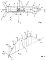
- the figure 2 shows an example of trajectory 12 that follows a projectile 1 according to the invention between its firing platform 13 and a target or objective B.
- This figure shows a reference centered at O (point where the platform or theoretical firing position 13 is located) and axes OX MB0 , OY MB0 and OZ MB0 .
- This reference is the land reference reference landmark which is chosen in this particular embodiment to implement the invention.
- the figure 3 shows as a reminder the three successive rotations which make it possible to pass from a fixed reference GX MB0 Y MB0 Z MB0 (OX mark MB0 Y MB0 Z MB0 centered in G after a vector translation OG) to the movable coordinate system GX p Y p Z p linked to the projectile.
- a first rotation of the X mark MB0 Y MB0 Z MB0 is performed around the Z axis MB0 , this rotation defines the angle ⁇ (or azimuth angle).
- the mark X 1 Y 1 Z 1 is then rotated around the axis Y 1 by an angle ⁇ (or attitude angle).
- the navigation of the projectile location of this one in the space
- the steps of guidance and control require to know at all times the angles of Euler ( ⁇ , ⁇ , ⁇ ) of the projectile in order to be able to locate the projectile by compared to its objective and thus be able to control the effects of the controls that are applied to the control surfaces.
- Gyrometers are expensive and fragile organs that do not withstand gunfire well.
- the invention proposes a method and a device that make it possible to dispense with gyrometers.
- This reference magnetic field will preferably be that measured at the firing position O. It will be measured for example by an axial tri-axial sensor linked to the firing platform 13 and having its detection axes oriented along the axes of the fixed landmark chosen (OX MB0 Y MB0 Z MB0 ).
- At least one azimuth angle value ⁇ n which can be considered as constant over at least part of the trajectory will be introduced into another memory or register of the computer.
- the projectiles fired at least have a part of their trajectory having a constant azimuth angle, it is their ballistic phase (T 1 on the figure 2 ).
- trajectory 12 For the non-ballistic phases of the trajectory of the projectile (piloted phases) it is also possible to decompose the theoretical trajectory curve 12 into several sections in which the azimuth angle can also be assumed to be constant.
- figure 2 shows a trajectory 12 comprising, after the ballistic phase T 1, six sections T 2 , T 3 , T 4 , T 5 , T 6 and T 7 on each of which the azimuth is substantially constant. It is of course possible to define a trajectory curve comprising a greater number of sections on each of which the azimuth is known.
- the trajectory profile 12 is known a priori. It is programmable before firing and can be correlated to an initialized clock during firing. This trajectory profile will thus be introduced in the form of a firing table in a memory of the projectile calculator. It is therefore also possible and in accordance with the invention to associate at a given moment a particular trajectory section having an azimuth angle ⁇ 1 , ⁇ 2 , ⁇ 3 , ⁇ 4 , ⁇ 5 , ⁇ 6 or ⁇ 7 .
- This azimuth angle will be used by the algorithm proposed by the invention to calculate the different angles of Euler for the portion of trajectory considered.
- measurements of the three components of the earth's magnetic field are finally made on the trajectory in the orthonormal frame linked to the projectile GX p Y p Z p .
- the different programmed values as well as the measured values are then used to calculate the roll and pitch angle of the projectile.
- the matrices making it possible to transform the magnetic field vector evaluated in the projectile marker into a vector evaluated in a fixed terrestrial reference frame.
- hp the magnetic field vector measured on board the projectile. This vector has components H px , H py and H pz in the reference linked to the projectile.
- H MB 0 the reference magnetic field vector. This vector has components H MB0x , H MB0y and H MB0z in the fixed terrestrial reference system.
- H p M ⁇ .M ⁇ .M ⁇ . H MB 0 expression which means that we pass from one vector to another by the product of three matrices of transformation and which can be written in a developed form:
- H px H py H pZ 1 0 0 0 cos ⁇ sin ⁇ 0 - sin ⁇ cos ⁇ cos ⁇ 0 sin ⁇ 0 1 0 - sin ⁇ 0 cos ⁇ cos ⁇ sin ⁇ 0 - sin ⁇ cos ⁇ 0 0 1 H MB 0 x H MB 0 there H MB 0 z
- H p M ⁇ .M ⁇ . H MB 0 expression in which M ⁇ represents a matrix which is the product of the two matrices relating to the angles ⁇ and ⁇ .
- the matrix M ⁇ has coefficients which will be noted later at ij .
- H px H py H pZ 1 0 0 0 cos ⁇ sin ⁇ 0 - sin ⁇ cos ⁇ at 11 at 12 at 13 at 21 at 22 at 23 at 31 at 32 at 33 H MB 0 x H MB 0 there H MB 0 z
- the invention proposes to remove the indeterminacy of these calculations by using at least one known and stored or programmed value before shooting the azimuth angle ⁇ .
- H px at 11 H MB0x + at 12 H MB0y + at 13 H MB0z .
- the attitude angle ⁇ is therefore immediately deduced from the values of the magnetic field (preprogrammed H MBO and measured H p ).
- This calculation may notably be performed on the ballistic trajectory portion of the projectile (T 1 ).
- H PY and H PZ are zero, it is a priori no longer possible to know the rolling position of the projectile with the previous calculation.
- Such a configuration appears when the projectile flies with its axis X P collinear Earth's magnetic field. To avoid such a problem, it suffices to shoot the projectile avoiding such a configuration.
- a suitable firing position O will be chosen and a shape of trajectory 12 leading to such collinearity will be avoided.
- the figure 4 shows an example of structural and functional organization of a device according to the invention.
- the computer 5 incorporates various calculation modules made in the form of algorithms stored in memories or registers.
- a first module 14 performs the calculation of the angles ⁇ , ⁇ and ⁇ from the programming data provided before firing by the programming means 8 or preprogrammed in the computer 5 and from the measurements of the components of the magnetic field made during the flight of the projectile by the triaxial magnetic sensor 7.
- the programming data incorporates a measurement of the three components of the reference magnetic field H MB0 in the fixed terrestrial reference centered on the firing position, a measurement which is stored in the memory 15.
- a second calculation module 18 realizes the derivation of the calculated angles and evaluates the components p, q and r of the instantaneous vector of rotation of the projectile.
- the guidance / control module 19 also uses the acceleration data of the projectile provided by the inertial means 9.
- This module controls the servomechanism 4 driving the control surfaces 3.
- This calculation is carried out in a specific azimuth evaluation module which uses the acceleration measurements provided by the inertial means 9 as well as an evaluation of the aerodynamic coefficient A of the projectile which is stored in memory (A is generally called the projectile incidence time constant).
- This azimuth calculation is made from a calculation of the angles made by the projection of the speed vector V of the shell in the planes GX MB0 Y MBO and GX MB0 Z MB0 of the fixed reference with respect to the axes of this reference.
- the figure 5a thus shows the skid plane GX MB0 Y MBO in which the projection V Y of the velocity vector of the shell makes an angle P (skid angle) with the axis GX P of the shell and an angle ⁇ Y (aerodynamic azimuth ) with GX axis MB0 .
- the azimuth angle ⁇ is also shown in this figure.
- the figure 5b shows the plane of incidence GX MB0 Z MBO in which the projection V Z of the velocity vector of the shell makes an angle ⁇ (angle of incidence) with the axis GX P of the shell and an angle ⁇ Z (slope aerodynamic) with GX axis MB0 .
- the attitude angle ⁇ is also represented in this figure.
- the inertial means 9 make it possible to determine at a time t the value of the components of the acceleration vector along the axes GX P , GY P and GZ P of the projectile.
- ⁇ n f ( ⁇ n , H n , H MB0 , ⁇ nT , ⁇ nT , ⁇ nT ) from which we deduce: ⁇ n and ⁇ n as well as the angles p n , q n and r n .
- This embodiment makes it possible to improve (for a duck-head projectile) the performances of the navigation method according to the invention by making it possible to overcome the majority of the errors related to magnetic and aerodynamic disturbances on the theoretical location of the azimuth zones. constant.
- the differences observed during disturbed trajectories are in all cases less than 2 ° to 3 ° for each angle, which is sufficient for a projectile having a short range trajectory (less than 10 km).
- deviations may be less than the degree if the magnetic disturbances are corrected and the ballistic disturbances are taken into account (for example by introducing a bias during firing).
- This sound is related to the fact that the angle is estimated from a tangent arc function whose result is between - ⁇ and + ⁇ (or between 0 and 2 ⁇ with a different choice of arc tangent function) and has a discontinuity the transition to the value ⁇ . This discontinuity disrupts the calculation of the derivative.
- This linearization is based on a priori knowledge of the amplitude of the jump of the roll angle which is 2 ⁇ each time.
- the figure 6 thus shows the value of the roll angle ⁇ calculated ("sawtooth" curve 21) and the linearized value (curve 22).
- the tangent arc function used will be corrected beforehand so as to give the value of the calculated arc a value between 0 and 2 ⁇ .
- the magnetic field measured by the triaxial magnetic sensor 7 is likely to be disturbed by the electromagnetic environment of the projectile 1.
- the most disturbing elements are the motors of the servomechanism 4 because they implement permanent magnets.
- the body of the projectile itself is also a source of disturbance of the measurements. Indeed its metallic mass induces a local deformation of the lines of the Earth's magnetic field.
- a similar method can be applied to correct the measurements along the transverse axes GY P and GZ P.
- the correction factor can be calculated only when the projectile will turn a little on itself (speed of at least 0.25 revolutions / second), which will occur a few seconds after the shot but still during the ballistic phase.
- the correction along the transverse axes is based on the fact that the measurements H PY and H PZ must be in theory sinusoidal and in phase quadrature. This means that, in theory, if a measure along the G YP direction is maximum, it must be zero on the GZ P path. Moreover, the modulus of the field remains constant during the flight (and normed to 1 in the calculations).
- the magnetic field H MB0 measured at the level of the firing platform 13 has been considered as reference value. This field is considered constant over the entire trajectory provided for the projectile.
- the invention will then simplify the guidance / control of a missile or a rocket by removing the gyrometers.
Description
Le domaine technique de l'invention est celui des procédés et dispositifs de navigation et/ou guidage et/ou pilotage d'un projectile vers une cible.The technical field of the invention is that of methods and devices for navigating and / or guiding and / or steering a projectile towards a target.
Le document
Le brevet
D'autre part, les projectiles connus sont guidés vers leur cible par un dispositif de guidage qui élabore les ordres de correction en accélération à appliquer au projectile pour diriger celui ci vers la cible.On the other hand, the known projectiles are guided towards their target by a guiding device which prepares the acceleration correction commands to be applied to the projectile to direct it to the target.
Ces ordres de correction sont utilisés ensuite par un dispositif de pilotage qui élabore les commandes à appliquer à des organes de pilotage afin d'assurer la correction souhaitée.These correction orders are then used by a control device that develops the commands to be applied to the steering members to ensure the desired correction.
Pour que le guidage et le pilotage puissent être assurés correctement il est nécessaire de connaître le positionnement et l'attitude du projectile dans un repère terrestre.In order for the guidance and steering to be ensured correctly, it is necessary to know the positioning and the attitude of the projectile in a terrestrial reference.
Le plus souvent le positionnement du projectile est connu grâce à un dispositif de positionnement par satellite (plus connu sous l'acronyme anglo saxon "GPS" signifiant «Global Positioning System»).Most often the positioning of the projectile is known thanks to a satellite positioning device (better known by the acronym "GPS" meaning "Global Positioning System").
Un tel dispositif permet au projectile de se localiser sur trajectoire. Par ailleurs le projectile reçoit avant tir une programmation qui lui donne les coordonnées de sa cible.Such a device allows the projectile to locate on trajectory. In addition, the projectile receives before shooting a program that gives it the coordinates of its target.
Il détermine alors lui-même sa position réelle en vol, et élabore, à l'aide des informations fournies par une unité de mesure inertielle embarquée et au moyen d'algorithmes appropriés, les ordres de commande destinés aux gouvernes.It then determines itself its actual position in flight, and develops, using the information provided by an onertial unit of measurement and by means of appropriate algorithms, control orders for control surfaces.
Cette unité de mesure inertielle, comprend des accéléromètres et des gyromètres (ou gyroscopes), qui fournissent (dans un repère lié au projectile) les composantes du vecteur instantané de rotation et de l'accélération non gravitationnelle à laquelle est soumis le projectile.This inertial measurement unit comprises accelerometers and gyroscopes, which provide (in a frame linked to the projectile) the components of the instantaneous vector of rotation and the non-gravitational acceleration to which the projectile is subjected.
Cette unité de mesure inertielle est mise en oeuvre pour connaître l'orientation du projectile et notamment déterminer les angles d'Euler permettant de passer d'un repère lié au projectile au repère fixe terrestre.This inertial measurement unit is used to know the orientation of the projectile and in particular to determine the angles of Euler allowing to pass from a reference linked to the projectile to the terrestrial fixed reference.
Elle permet également d'assurer le pilotage du projectile et de concourir à son guidage en fusionnant les données de cette unité avec celles fournies par le GPS.It also allows to control the projectile and contribute to its guidance by merging the data of this unit with that provided by the GPS.
Si une telle solution est bien adaptée aux projectiles de type missiles, elle est inutilisable pour les projectiles tirés canon en raison du manque de robustesse des gyromètres ou du coût trop élevé de ces composants de mesureIf such a solution is well suited to missile-type projectiles, it is unusable for projectiles fired gun because of the lack of robustness of the gyrometers or the cost too high of these measuring components
C'est le but de l'invention que de proposer un procédé de navigation et/ou de guidage et/ou de pilotage d'un projectile vers une cible ou un objectif et permettant de pallier de tels inconvénients.It is the object of the invention to provide a method of navigation and / or guidance and / or control of a projectile to a target or an objective and to overcome such drawbacks.
Ainsi l'invention a pour objet un procédé permettant d'assurer la navigation et/ou le guidage et/ou le pilotage d'un projectile vers un objectif, procédé dans lequel on utilise un calcul de tout ou partie des angles d'Euler du projectile pour permettre la détermination de l'attitude et/ou la localisation du projectile dans un repère terrestre, procédé caractérisé en ce que :
- on introduit avant tir dans une mémoire ou registre d'un calculateur du projectile au moins une valeur des trois composantes d'un champ magnétique de référence dans un repère terrestre fixe, direct et orthonormé, repère centré sur la position de tir et ayant un axe horizontal et un axe vertical, l'orientation du repère par rapport à la direction de l'objectif étant connue et fixée ou programmée,
- on fixe par construction ou on programme avant tir dans une autre mémoire ou registre du calculateur, au moins une valeur d'angle d'azimut,
- on réalise sur trajectoire au moins une mesure des trois composantes du champ magnétique dans un repère orthonormé lié au projectile,
- on calcule sur trajectoire l'angle de roulis et/ou l'angle d'assiette à partir des valeurs de champ magnétique mesurées, du ou des valeurs du champ de référence et de la valeur d'angle d'azimut mémorisée pour la partie de trajectoire considérée.
- is introduced before firing into a memory or register of a projectile calculator at least one value of the three components of a reference magnetic field in a fixed, direct and orthonormal terrestrial reference, reference centered on the firing position and having an axis horizontal and a vertical axis, the orientation of the marker with respect to the direction of the objective being known and fixed or programmed,
- one fixes by construction or program before shooting in another memory or register of the calculator, at least one value of angle of azimuth,
- at least one measurement of the three components of the magnetic field is carried out on a trajectory in an orthonormal reference linked to the projectile,
- the roll angle and / or attitude angle is calculated from the measured magnetic field values, the reference field value (s) and the stored azimuth angle value for the part of the vehicle. trajectory considered.
Avantageusement le repère terrestre fixe sera choisi centré sur la position de tir et ayant un axe horizontal orienté en direction de l'objectif.Advantageously, the fixed terrestrial reference will be chosen centered on the firing position and having a horizontal axis oriented in the direction of the objective.
La valeur du champ magnétique de référence pourra être mesurée avant tir au niveau de la position de tir et introduite en mémoire, le calcul du ou des angles étant ensuite réalisé à partir de cette mesure.The value of the reference magnetic field can be measured before firing at the firing position and introduced in memory, the calculation of the angle or angles being then made from this measurement.
On pourra calculer l'angle d'assiette θ à partir d'au moins une mesure de la composante HPX du champ magnétique suivant l'axe XP du projectile par la formule suivante : ![]()
b et c sont des coefficients qui sont fonctions des composantes HMB0X, HMB0Y et HMB0Z du champ magnétique de référence dans le repère terrestre fixe telles que programmées avant tir et ψn étant une valeur de l'angle d'azimut connue sur la partie de trajectoire considérée.The attitude angle θ can be calculated from at least one measurement of the H PX component of the magnetic field along the X P axis of the projectile by the following formula: ![]()
b and c are coefficients which are functions of the components H MB0X , H MB0Y and H MB0Z of the reference magnetic field in the fixed terrestrial frame as programmed before firing and ψ n being a value of the known azimuth angle on the part of the trajectory considered.
On pourra ensuite calculer l'angle de roulis ϕ à partir du calcul de l'angle d'assiette et en utilisant au moins une mesure des composantes HPY et HPZ du champ magnétique suivant les axe YP et ZP du projectile par la formule suivante : ![]()
d et e étant des coefficients fonctions des composantes HMB0X, HMB0Y et HMB0Z du champ magnétique de référence dans le repère terrestre fixe telles que programmées avant tir et des coefficients d'une matrice M(θ,ψ) de passage partiel du repère terrestre fixe au repère lié au projectile et ne faisant intervenir que les angles d'azimut et d'assiette.The roll angle φ can then be calculated from the calculation of the attitude angle and by using at least one measurement of the components H PY and H PZ of the magnetic field along the Y axis P and Z P of the projectile by the following formula: ![]()
d and e being function coefficients of the components H MB0X , H MB0Y and H MB0Z of the reference magnetic field in the fixed terrestrial reference as programmed before firing and of the coefficients of a matrix M (θ, ψ) of partial passage of the reference mark ground fixed to the marker related to the projectile and involving only the azimuth angles and trim.
Après calcul de l'angle de roulis ϕ on procèdera avantageusement à une linéarisation de sa valeur.After the roll angle φ has been calculated, a linearization of its value is advantageously carried out.
Suivant un mode de réalisation, pour une phase de vol balistique, l'angle d'azimut ψn = ψ1 sera fixé en mémoire ou programmé avant tir et correspondra à l'angle d'azimut donné au projectile lors du tir.According to one embodiment, for a ballistic flight phase, the azimuth angle ψ n = ψ 1 will be fixed in memory or programmed before firing and will correspond to the azimuth angle given to the projectile during firing.
Suivant un autre mode de réalisation, pour une phase de vol piloté, l'angle d'azimut ψn adopté pour la partie de trajectoire considérée sera une valeur qui sera mémorisée avant tir et incorporée dans une table de tir qui sera lue en relation avec une horloge décomptée à partir de l'instant de tir.According to another embodiment, for a piloted flight phase, the azimuth angle ψ n adopted for the part of trajectory considered will be a value that will be memorized before firing and incorporated in a firing table that will be read in relation with a clock counted from the instant of fire.
Suivant un autre mode de réalisation, pour une phase de vol piloté, l'angle d'azimut ψn adopté pour la partie de trajectoire considérée sera une valeur qui sera calculée sur trajectoire à partir des coefficients aérodynamique du projectile, d'au moins une mesure de l'accélération et d'au moins une valeur fixée en mémoire ou programmée d'un angle d'azimut.According to another embodiment, for a piloted flight phase, the azimuth angle ψ n adopted for the part of trajectory considered will be a value which will be calculated on trajectory from the aerodynamic coefficients of the projectile, at least one measurement of the acceleration and at least one value fixed in memory or programmed by an azimuth angle.
On pourra par ailleurs évaluer les composantes du vecteur instantané de rotation du projectile dans un repère lié au projectile à partir des valeurs des angles d'Euler calculées ainsi que de leurs dérivées en fonction du temps.We can also evaluate the components of the instantaneous vector of rotation of the projectile in a reference linked to the projectile from the calculated values of Euler angles and their derivatives as a function of time.
Avantageusement, afin de corriger les mesures de champ magnétique d'une partie des perturbations apportées par l'environnement des capteurs, on pourra procéder à au moins une correction pendant une phase ayant un angle d'azimut stable, correction comprenant une mesure d'un écart entre le champ magnétique théorique et le champ magnétique mesurée.Advantageously, in order to correct the magnetic field measurements of a part of the disturbances brought by the environment of the sensors, it will be possible to carry out at least one correction during a phase having a stable azimuth angle, correction comprising a measurement of a difference between the theoretical magnetic field and the measured magnetic field.
Pour réaliser la correction on pourra utiliser au moins une valeur programmée ou mémorisée de l'angle d'azimut et au moins une valeur programmée ou mémorisée de l'angle d'assiette.To carry out the correction, at least one programmed or memorized value of the azimuth angle and at least one programmed or memorized value of the attitude angle can be used.
L'invention a également pour objet un dispositif permettant d'assurer la navigation et/ou le guidage et/ou le pilotage d'un projectile, dispositif comportant au moins un capteur magnétique assurant la mesure des trois composantes du champ magnétique dans un repère orthonormé lié au projectile, dispositif mettant en oeuvre le procédé selon l'invention et caractérisé en ce qu'il comprend au moins un calculateur incorporant un algorithme de calcul des angles d'Euler, calculateur associé à des moyens mémoires couplés à des moyens fournissant avant tir des données de programmation desdites mémoires, les moyens mémoires étant destinés à stocker au moins une valeur des trois composantes d'un champ magnétique de référence dans un repère terrestre fixe, ces données de programmation étant utilisées par le calculateur avec les mesures du champ magnétique sur trajectoire pour déterminer, pour au moins une partie de trajectoire ayant un angle d'azimut sensiblement constant, tout ou partie des angles d'Euler et permettre d'assurer ainsi la navigation et/ou le guidage et/ou le pilotage du projectile.The invention also relates to a device for providing navigation and / or guidance and / or control of a projectile, device comprising at least one magnetic sensor for measuring the three components of the magnetic field in an orthonormal frame related to the projectile, device implementing the method according to the invention and characterized in that it comprises at least one computer incorporating an algorithm for calculating Euler angles, calculator associated with memory means coupled to means providing before shooting programming data of said memories, the memory means being intended to store at least one value of the three components of a reference magnetic field in a fixed terrestrial reference, these programming data being used by the computer with the measurements of the magnetic field on trajectory for determining, for at least a portion of trajectory having a substantially consistent azimuth angle so, all or part of Euler angles and allow to ensure the navigation and / or guidance and / or control of the projectile.
Le projectile pourra également comporter des moyens inertiels.The projectile may also include inertial means.
Le calculateur pourra incorporer des moyens permettant de corriger les mesures de champ magnétique d'une partie des perturbations apportées par l'environnement des capteurs.The computer may incorporate means for correcting the magnetic field measurements of part of the disturbances brought by the environment of the sensors.
L'invention sera mieux comprise à la lecture de la description qui va suivre d'un mode particulier de réalisation, description faite en référence aux dessins annexés et dans lesquels :
- la
figure 1 est un schéma montrant un projectile mettant en oeuvre un dispositif de navigation et/ou guidage et/ou pilotage selon l'invention, - la
figure 2 montre un exemple de vol de projectile vers un objectif et les principales données mises en oeuvre dans les différents calculs, - la
figure 3 montre les trois rotations successives choisies et qui permettent de passer d'un repère fixe à un repère mobile, - la
figure 4 est un schéma d'architecture fonctionnelle du dispositif selon l'invention, - les
figures 5a et 5b montrent comment se situent les angles de dérapage et d'incidence, - la
figure 6 montre la linéarisation de l'angle de roulis.
- the
figure 1 is a diagram showing a projectile implementing a device for navigation and / or guidance and / or piloting according to the invention, - the
figure 2 shows an example of projectile flight towards an objective and the main data implemented in the various calculations, - the
figure 3 shows the three successive rotations chosen and which make it possible to pass from a fixed reference point to a movable marker, - the
figure 4 is a functional architecture diagram of the device according to the invention, - the
Figures 5a and 5b show how the skid angles and incidence angles are - the
figure 6 shows the linearization of the roll angle.
La
Le projectile 1 est équipé à sa partie arrière d'un empennage de stabilisation déployable 2 et à sa partie avant de quatre gouvernes canards 3, également déployables.The projectile 1 is equipped at its rear part with a deployable stabilizing
Un moyen de pilotage ou servomécanisme 4 assure l'entraînement en rotation des différents canards 3 pour réaliser le pilotage du projectile. Ce moyen n'est pas représenté en détails et il pourra comporter deux ou quatre motoréducteurs (un par canard ou bien un par plan de pilotage).A driving means or
Ce projectile est par exemple un projectile tiré par un canon en direction d'un objectif.This projectile is for example a projectile fired by a cannon towards a goal.
Lorsque le projectile se trouve à l'intérieur du tube d'une arme (non représentée) les ailettes de l'empennage et les canards sont repliés le long du corps du projectile 1 ou bien se logent dans le corps du projectile. Ils se déploient à la sortie du tube pour assurer leurs fonctions de stabilisation ou de pilotage.When the projectile is inside the tube of a weapon (not shown) the fins of the empennage and the ducks are folded along the body of the projectile 1 or lodge in the body of the projectile. They deploy at the exit of the tube to perform their stabilization or steering functions.
Les mécanismes de déploiement d'empennage ou de gouvernes ainsi que les moyens d'entraînement des gouvernes canards sont bien connus de l'Homme du Métier et ne font pas partie de la présente invention. On pourra se reporter aux brevets
Le pivotement des canards est commandé par un calculateur embarqué 5.The pivoting of the ducks is controlled by an
Le projectile 1 renferme également une tête militaire 6, par exemple une charge formée, une charge explosive ou bien une ou plusieurs sous munitions dispersables.The projectile 1 also encloses a
Selon une caractéristique importante de l'invention, le projectile 1 incorpore un senseur magnétique triaxial 7 (un senseur unique ou bien trois sondes magnétiques ou magnéto-résistances réparties suivant trois directions différentes d'un trièdre de mesure, par exemple trois sondes orthogonales entre elles et dirigées chacune de préférence suivant un des axes du repère lié au projectile GXp, GYp ou GZp).According to an important characteristic of the invention, the projectile 1 incorporates a triaxial magnetic sensor 7 (a single sensor or three magnetic probes or magneto-resistors distributed in three different directions of a measurement trihedron, for example three orthogonal probes between them and each preferably directed along one of the axes of the reference linked to the projectile GX p , GY p or GZ p ).
Ce senseur permet de mesurer les composantes du champ magnétique terrestre H dans un repère lié au projectile 1.This sensor makes it possible to measure the components of the terrestrial magnetic field H in a reference linked to the projectile 1.
Le senseur magnétique 7 est relié au calculateur 5 qui assure le traitement des mesures et leur exploitation ultérieure.The
Le projectile 1 comporte également une interface 8 de programmation du calculateur. Cette interface est destinée à coopérer avec un moyen de programmation (non représenté) solidaire de l'arme. Elle est reliée au calculateur 5.The projectile 1 also includes an
On pourra par exemple prévoir un moyen de programmation inductif (tel que décrit par un des brevets
On pourrait d'une façon plus simple prévoir des zones de contacts électriques coopérant avec le programmateur de l'arme.One could more simply provide zones of electrical contacts cooperating with the programmer of the weapon.
Le projectile 1 renferme enfin des moyens inertiels. Ces moyens inertiels 9 comprennent trois accéléromètres 10a,10b,10c orientés respectivement suivant les axes de roulis (GXp), de lacet (GYp) et de tangage (GZp) du projectile 1.The projectile 1 finally contains inertial means. These inertial means 9 comprise three
Les moyens inertiels 9 sont destinés d'une façon classique à permettre notamment la mise en oeuvre des lois de pilotage.The inertial means 9 are intended in a conventional manner to allow in particular the implementation of control laws.
Les moyens inertiels 9 sont reliés au calculateur 5 qui assure le traitement des mesures effectuées et leur exploitation ultérieure pour la navigation, le guidage et/ou le pilotage du projectile.The inertial means 9 are connected to the
Bien entendu la
Le projectile pourra également comprendre un détecteur de cible 11 afin de permettre une poursuite de cette dernière lorsque le projectile se trouve en phase terminale de sa trajectoire.The projectile may also include a
La
On a représenté sur cette figure un repère centré en O (point où est située la plate-forme ou position théorique de tir 13) et d'axes OXMB0, OYMB0 et OZMB0. Ce repère est le repère terrestre fixe de référence qui est choisi dans ce mode particulier de réalisation pour mettre en oeuvre l'invention.This figure shows a reference centered at O (point where the platform or
C'est un repère direct et orthonormé qui a un axe horizontal OXMB0 orienté en direction de l'objectif B et un axe vertical OZMB0 (l'axe OYMB0 se déduit des deux autres pour que le repère soit orthonormé et direct).It is a direct and orthonormal reference that has a horizontal axis OX MB0 oriented towards the objective B and a vertical axis OZ MB0 (the axis OY MB0 is deduced from the other two so that the marker is orthonormal and direct).
C'est par rapport à ce repère de référence que seront évalués les angles d'Euler que forment les axes du repère lié au projectile GXpYpZp.It is with respect to this benchmark that will be evaluated Euler angles that form the axes of the reference related to the projectile GX p Y p Z p .
La
Une première rotation du repère XMB0YMB0ZMB0 est effectuée autour de l'axe ZMB0, cette rotation définit l'angle ψ (ou angle d'azimut). Le repère orthonormé direct obtenu a pour axes X1, Y1 (perpendiculaire à X1 et Z1) et Z1=ZMB0.A first rotation of the X mark MB0 Y MB0 Z MB0 is performed around the Z axis MB0 , this rotation defines the angle ψ (or azimuth angle). The direct orthonormal reference obtained has for axes X 1 , Y 1 (perpendicular to X 1 and Z 1 ) and Z 1 = Z MB0 .
On fait ensuite pivoter le repère X1Y1Z1 autour de l'axe Y1 d'un angle θ (ou angle d'assiette). Le nouveau repère orthonormé direct obtenu a pour axes Z2, Y2 (Y2=Y1) et X2 (perpendiculaire à Z2 et Y2).The mark X 1 Y 1 Z 1 is then rotated around the axis Y 1 by an angle θ (or attitude angle). The new direct orthonormal reference obtained has for axes Z 2 , Y 2 (Y 2 = Y 1 ) and X 2 (perpendicular to Z 2 and Y 2 ).
On fait enfin pivoter le repère X2Y2Z2 autour de l'axe X2 d'un angle ϕ (ou angle de roulis). Le nouveau repère orthonormé direct obtenu a pour axes Xp=X2, Yp et Zp.Finally, the reference X 2 Y 2 Z 2 is rotated about the axis X 2 by an angle φ (or roll angle). The new direct orthonormal reference obtained has for axes X p = X 2 , Yp and Z p .
La navigation du projectile (localisation de celui ci dans l'espace) ainsi que les étapes de guidage et de pilotage nécessitent de connaître à tout instant les angles d'Euler (ψ,θ,ϕ) du projectile afin de pouvoir situer le projectile par rapport à son objectif et de pouvoir ainsi maîtriser les effets des commandes qui sont appliquées aux gouvernes.The navigation of the projectile (location of this one in the space) as well as the steps of guidance and control require to know at all times the angles of Euler (ψ, θ, φ) of the projectile in order to be able to locate the projectile by compared to its objective and thus be able to control the effects of the controls that are applied to the control surfaces.
Habituellement cette connaissance des angles d'Euler est fournie par une plate-forme inertielle complète comprenant trois accéléromètres et trois gyromètres.Usually this knowledge of Euler angles is provided by a complete inertial platform comprising three accelerometers and three gyrometers.
Les gyromètres sont des organes coûteux et fragiles qui résistent mal au tir canon.Gyrometers are expensive and fragile organs that do not withstand gunfire well.
L'invention propose un procédé et un dispositif qui permettent de se passer de gyromètres.The invention proposes a method and a device that make it possible to dispense with gyrometers.
Conformément à l'invention on va dans un premier temps introduire avant le tir dans une mémoire (ou registre) du calculateur 5 au moins une valeur des trois composantes d'un champ magnétique de référence dans le repère terrestre fixe choisi OXMB0YMB0ZMB0.According to the invention, it will first be introduced before firing into a memory (or register) of the
Ce champ magnétique de référence sera de préférence celui mesuré au niveau de la position de tir O. Il sera mesuré par exemple par un senseur magnétique tri axial lié à la plate-forme de tir 13 et ayant ses axes de détection orientés suivant les axes du repère fixe choisi (OXMB0YMB0ZMB0).This reference magnetic field will preferably be that measured at the firing position O. It will be measured for example by an axial tri-axial sensor linked to the
Par ailleurs on introduira dans une autre mémoire ou registre du calculateur 5 au moins une valeur d'angle d'azimut ψn qui peut être considérée comme constante sur au moins une partie de la trajectoire.Furthermore, at least one azimuth angle value ψ n which can be considered as constant over at least part of the trajectory will be introduced into another memory or register of the computer.
En effet les projectiles tirés canon comportent au moins une partie de leur trajectoire ayant un angle d'azimut constant, c'est leur phase balistique (T1 sur la
Pour les phases non balistiques de la trajectoire du projectile (phases pilotées) il est également possible de décomposer la courbe de trajectoire théorique 12 en plusieurs tronçons dans lesquels l'angle d'azimut peut être également supposé constant. A titre d'exemple la
Le profil de trajectoire 12 est connu a priori. Il est programmable avant tir et peut être corrélé à une horloge initialisée lors du tir. Ce profil de trajectoire sera ainsi introduit sous la forme d'une table de tir dans une mémoire du calculateur du projectile. On pourra donc également et conformément à l'invention associer à un instant donné un tronçon de trajectoire particulier ayant un angle d'azimut ψ1, ψ2, ψ3, ψ4, ψ5, ψ6 ou ψ7.The
Cet angle d'azimut sera utilisé par l'algorithme proposé par l'invention pour calculer les différents angles d'Euler pour la portion de trajectoire considérée.This azimuth angle will be used by the algorithm proposed by the invention to calculate the different angles of Euler for the portion of trajectory considered.
Conformément à l'invention on réalise enfin sur trajectoire des mesures des trois composantes du champ magnétique terrestre dans le repère orthonormé lié au projectile GXpYpZp.In accordance with the invention, measurements of the three components of the earth's magnetic field are finally made on the trajectory in the orthonormal frame linked to the projectile GX p Y p Z p .
Les différentes valeurs programmées ainsi que les valeurs mesurées sont ensuite utilisées pour calculer les angles de roulis et d'assiette du projectile.The different programmed values as well as the measured values are then used to calculate the roll and pitch angle of the projectile.
Pour procéder à ces calculs on considèrera les matrices permettant de transformer le vecteur champ magnétique évalué dans le repère projectile en un vecteur évalué dans un repère terrestre fixe.To carry out these calculations, the matrices making it possible to transform the magnetic field vector evaluated in the projectile marker into a vector evaluated in a fixed terrestrial reference frame.
On notera
On notera
On peut écrire : 
On voit que l'on passe d'un vecteur à l'autre par des produits matriciels successifs faisant intervenir les angles d'Euler que l'on cherche à déterminer.We see that we go from one vector to another by successive matrix products involving the Euler angles that we want to determine.
On peut également noter cette transformation de la façon suivante : 
On voit avec une telle décomposition que, si θ et ψ sont connus, il est possible de déterminer l'angle de roulis ϕ (les deux expressions du champ magnétique étant en effet connues par ailleurs car programmées (HMB0) ou mesurées (Hp).It can be seen with such a decomposition that, if θ and ψ are known, it is possible to determine the roll angle φ (the two expressions of the magnetic field being known otherwise because programmed (H MB0 ) or measured (H p ).
L'invention propose de lever l'indétermination de ces calculs en utilisant au moins une valeur connue et mémorisée ou bien programmée avant tir de l'angle d'azimut ψ.The invention proposes to remove the indeterminacy of these calculations by using at least one known and stored or programmed value before shooting the azimuth angle ψ.
On remarque en effet que la mesure de la composante Hpx du champ magnétique suivant l'axe Xp ne dépend pas du roulis ϕ.It is noted that the measurement of the component H px of the magnetic field along the axis X p does not depend on the roll φ.
Elle s'écrit en effet : ![]()
![]()
Ou d'une façon plus explicite : ![]()
![]()
![]()
![]()
Lorsque l'angle d'azimut ψ est connu, l'angle d'assiette θ se déduit donc immédiatement des valeurs du champ magnétique (HMBO préprogrammée et Hp mesurée).When the azimuth angle ψ is known, the attitude angle θ is therefore immediately deduced from the values of the magnetic field (preprogrammed H MBO and measured H p ).
Les angles d'azimut et d'assiette étant connus, on calculera aisément l'angle de roulis ϕ.The azimuth and attitude angles being known, it will be easy to calculate the roll angle φ.
On le calculera par la formule suivante : ![]()
![]()
![]()
![]()
![]()
![]()
Ces calculs de θ et de ϕ pourront être réalisés sur toute portion de trajectoire Ti dans laquelle un angle d'azimut ψi peut être considéré comme sensiblement constant et se trouve donc pré déterminé.These calculations of θ and φ can be performed on any trajectory portion T i in which an azimuth angle ψ i can be considered substantially constant and is thus pre-determined.
On pourra notamment réaliser ce calcul sur la portion de trajectoire balistique du projectile (T1). Dans ce cas l'angle d'azimut ψn = ψ1, programmé avant tir, correspond à l'angle d'azimut donné au projectile lors du tir.This calculation may notably be performed on the ballistic trajectory portion of the projectile (T 1 ). In this case, the azimuth angle ψ n = ψ 1 , programmed before firing, corresponds to the azimuth angle given to the projectile during firing.
On pourra aussi, en phase de vol piloté, réaliser ces calculs pour les différents angles d'azimut ψn successivement adoptés.It will also be possible, in controlled flight phase, to perform these calculations for the different azimuth angles ψ n successively adopted.
On pourra ainsi d'une façon simple lire la valeur de l'angle d'azimut dans une table de tir mise en mémoire dans le calculateur 5 et lue en relation avec une horloge décomptée à partir de l'instant de tir.It is thus possible in a simple way to read the value of the azimuth angle in a firing table stored in the
D'autres façons de choisir la valeur de l'angle d'azimut sont possibles et seront décrites dans la suite de la présente description.Other ways of choosing the value of the azimuth angle are possible and will be described later in this description.
On notera que si HPY et HPZ sont nuls, il n'est a priori plus possible de connaître la position en roulis du projectile avec le calcul précédent. Une telle configuration apparaît lorsque le projectile vole avec son axe XP colinéaire au champ magnétique terrestre. Il suffit pour éviter un tel problème de tirer le projectile en évitant une telle configuration. On choisira une position de tir O appropriée et on évitera une forme de trajectoire 12 conduisant à une telle colinéarité.Note that if H PY and H PZ are zero, it is a priori no longer possible to know the rolling position of the projectile with the previous calculation. Such a configuration appears when the projectile flies with its axis X P collinear Earth's magnetic field. To avoid such a problem, it suffices to shoot the projectile avoiding such a configuration. A suitable firing position O will be chosen and a shape of
Une fois les angles d'Euler ψ, θ et ϕ calculés, on pourra facilement évaluer les composantes du vecteur instantané de rotation Ω du projectile dans un repère mobile lié au projectile.Once the Euler angles ψ, θ and φ have been calculated, we can easily evaluate the components of the instantaneous vector of rotation Ω of the projectile in a moveable reference system linked to the projectile.
La connaissance de ce vecteur est indispensable pour conduire les étapes habituelles de navigation, guidage et pilotage d'un projectile.The knowledge of this vector is essential to lead the usual steps of navigation, guidance and control of a projectile.
Les composantes de ce vecteur sont : 
Avec ![]()
![]()
![]()
![]()
![]()
![]()
On voit ainsi qu'il est possible d'obtenir les trois composantes du vecteur rotation sans avoir recours à un gyromètre.It is thus seen that it is possible to obtain the three components of the rotation vector without resorting to a gyrometer.
On remarquera qu'au cours des différentes phases d'évaluation dans lesquelles l'angle d'azimut est considéré comme constant, notamment au cours de la phase balistique du projectile, la vitesse de rotation en roulis p pourra être tout simplement approximée à ![]()
![]()
La
Le calculateur 5 incorpore différents modules de calcul réalisés sous la forme d'algorithmes mis en mémoires ou registres.The
Un premier module 14 effectue le calcul des angles ψ, θ et ϕ à partir des données de programmations fournies avant le tir par les moyens de programmation 8 ou pré programmées dans le calculateur 5 et à partir des mesures des composantes du champ magnétique effectuées pendant le vol du projectile par le senseur magnétique triaxial 7.A
Les données de programmation incorporent une mesure des trois composantes du champ magnétique HMB0 de référence dans le repère terrestre fixe centré sur la position de tir, mesure qui est stockée dans la mémoire 15.The programming data incorporates a measurement of the three components of the reference magnetic field H MB0 in the fixed terrestrial reference centered on the firing position, a measurement which is stored in the
Elles incorporent également une ou plusieurs valeurs d'angle d'azimut ψn considérées comme connues a priori sur une partie différente de la trajectoire.They also incorporate one or more azimuth angle values ψ n considered as known a priori on a different part of the trajectory.
Ces valeurs sont associées par exemple à une table de tir mise dans une mémoire 16 et dont l'exploitation est faite par l'algorithme en liaison avec l'information de temps donnée par une horloge 17 qui est initialisée après détection du tir du projectile (par des moyens classiques non représentés, par exemple un capteur de l'accélération initiale).These values are associated for example with a firing table placed in a
Un deuxième module de calcul 18 réalise la dérivation des angles calculés et évalue les composantes p, q et r du vecteur instantané de rotation du projectile.A
Ces éléments sont exploités dans un troisième module 19 de guidage et/ou de pilotage qui met en oeuvre des lois de guidage ou pilotage connues et qu'il n'est pas nécessaire de décrire ici en détails.These elements are used in a
Le module de guidage / pilotage 19 utilise par ailleurs les données d'accélération du projectile fournies par les moyens inertiels 9.The guidance /
Ce module assure la commande du servomécanisme 4 entraînant les gouvernes 3.This module controls the
La description précédente a été faite avec un repère de référence centré sur la position de tir et ayant un axe horizontal OXMB0 orienté en direction de l'objectif.The foregoing description was made with a reference mark centered on the firing position and having a horizontal axis OX MB0 oriented toward the objective.
Il serait bien entendu possible de choisir un repère de référence orienté différemment. Pour mettre en oeuvre l'invention, il sera cependant nécessaire alors de définir l'orientation des axes du repère de référence par rapport à la direction OB (droite joignant la plate forme de tir à l'objectif). Les calculs ultérieurs utiliseront alors des matrices de transfert assurant le passage du repère de référence au repère dont l'axe OXMB0 est orienté vers l'objectif pour définir les différents angles. Ces éléments d'orientation du repère de référence seront par exemple programmés avant tir en même temps que les composantes du champ magnétique dans le repère de référence ainsi que la ou les valeurs de l'angle d'azimut ψ.It would of course be possible to choose a reference reference oriented differently. To implement the invention, however, it will be necessary then to define the orientation of the axes of the reference frame with respect to the OB direction (right joining the shooting platform to the objective). The subsequent calculations will then use transfer matrices ensuring the passage of the reference mark to the mark whose axis OX MB0 is oriented towards the objective to define the different angles. These orientation elements of the reference mark will, for example, be programmed before firing together with the components of the magnetic field in the reference mark and the value or values of the azimuth angle ψ.
A titre de variante il serait possible de définir un système d'arme (associant plate-forme de tir et projectile) conçu de telle sorte que l'azimut initial ψ0 soit toujours nul. Une telle variante permet d'éviter d'avoir à programmer la valeur initiale de l'azimut, cette valeur ψ=0 qui est fixée sera alors incorporée dans le calculateur 5 du projectile comme une donnée de calcul initiale. Il est cependant nécessaire alors de programmer les éléments d'orientation du repère de référence si ce dernier n'est pas choisi avec son axe OX orienté en direction de l'objectif.As a variant it would be possible to define a weapon system (combining firing platform and projectile) designed such that the initial azimuth ψ 0 is always zero. Such a variant makes it possible to avoid having to program the initial value of the azimuth, this value ψ = 0 which is fixed will then be incorporated in the
Concrètement adopter ψ=0 revient à choisir de tirer toujours dans le plan vertical OXZ du repère de référence choisi.Concretely adopt ψ = 0 is to choose to always shoot in the vertical plane OXZ of the reference reference chosen.
A titre de variante il est possible de remplacer la mise en mémoire d'une table de tir donnant les différents angles d'azimut par une valeur ψn qui est calculée d'une façon continue sur trajectoire à partir des coefficients aérodynamique du projectile et d'une mesure de l'accélération.As a variant it is possible to replace the storage of a firing table giving the different azimuth angles by a value ψ n which is calculated continuously on a trajectory from the aerodynamic coefficients of the projectile and the a measure of acceleration.
Ce calcul est réalisé dans un module d'évaluation d'azimut 20 spécifique qui utilise les mesures d'accélération fournies par les moyens inertiels 9 ainsi qu'une évaluation du coefficient aérodynamique A du projectile qui est mise en mémoire (A est appelée généralement la constante de temps d'incidence du projectile).This calculation is carried out in a specific azimuth evaluation module which uses the acceleration measurements provided by the inertial means 9 as well as an evaluation of the aerodynamic coefficient A of the projectile which is stored in memory (A is generally called the projectile incidence time constant).
Ce calcul d'azimut est réalisé à partir d'un calcul des angles que fait la projection du vecteur vitesse V de l'obus dans les plans GXMB0YMBO et GXMB0ZMB0 du repère fixe par rapport aux axes de ce repère.This azimuth calculation is made from a calculation of the angles made by the projection of the speed vector V of the shell in the planes GX MB0 Y MBO and GX MB0 Z MB0 of the fixed reference with respect to the axes of this reference.
La
La
Les moyens inertiels 9 permettent de déterminer à un instant t la valeur des composantes du vecteur accélération suivant les axes GXP, GYP et GZP du projectile.The inertial means 9 make it possible to determine at a time t the value of the components of the acceleration vector along the axes GX P , GY P and GZ P of the projectile.
On met en oeuvre la formule classique liant la valeur de l'angle d'azimut ψ au coefficient aérodynamique A et à l'angle εY pour un projectile piloté par gouvernes canards.![]()
![]()
Une intégration des composantes du vecteur accélération mesuré permet de déterminer les composantes du vecteur vitesse. Ce dernier est projeté sur le plan GXMB0YMBO en utilisant une matrice de transfert M(ψ,θ,ϕ) faisant intervenir les angles d'Euler.An integration of the components of the measured acceleration vector makes it possible to determine the components of the velocity vector. The latter is projected onto the GX plane MB0 Y MBO using a transfer matrix M (ψ, θ, φ) involving the Euler angles.
On voit que ce type de calcul de l'angle d'azimut impose de connaître cette matrice, donc également l'angle d'azimut. En fait, conformément à l'invention, on s'appuiera sur une valeur initiale connue de l'angle d'azimut ψn (par exemple celle préprogrammée, ou bien fixée par construction dans le calculateur (telle que ψ=0) et correspondant à la phase balistique).We see that this type of calculation of the azimuth angle requires knowing this matrix, so also the azimuth angle. In fact, according to the invention, we will rely on a known initial value of the azimuth angle ψ n (for example that preprogrammed, or fixed by construction in the calculator (such that ψ = 0) and corresponding to the ballistic phase).
Puis on déterminera de proche en proche les valeurs de l'angle d'azimut à partir des valeurs calculées précédemment.Then we will gradually determine the values of the azimuth angle from the previously calculated values.
On met pour cela en oeuvre les étapes décrites précédemment pour déterminer les angles θ et ϕ à l'aide des mesures du champ magnétique ainsi que des valeurs de champ de référence préprogrammées.To do this, the steps described above are used to determine the angles θ and φ using magnetic field measurements as well as pre-programmed reference field values.
Puis on procédera par itérations successives suivant une période d'échantillonnage T donnée.Then we proceed by successive iterations following a given sampling period T.
On déterminera ainsi à l'instant t=n la valeur de l'angle d'azimut ψn à partir des valeurs de l'accélération mesurée à l'instant t=n et avec les coefficients de la matrice M(ψ,θ,ϕ) calculés à l'instant t = n-T.Thus, at time t = n, the value of the azimuth angle ψ n will be determined from the values of the acceleration measured at time t = n and with the coefficients of matrix M (ψ, θ, φ) calculated at time t = nT.
A un instant t = n donné on a donc :
ψn = f (γn,Hn,HMB0,ψn-T,θn-T,ϕn-T) dont on déduit: θn et ϕn ainsi que les angles pn, qn et rn.At a given moment t = n we have:
ψ n = f (γ n , H n , H MB0 , ψ nT , θ nT , φ nT ) from which we deduce: θ n and φ n as well as the angles p n , q n and r n .
Il suffit de réitérer cette évaluation le long de la trajectoire du projectile pour avoir, sans gyromètres, les paramètres nécessaires à la navigation, au guidage et au pilotage.It is sufficient to repeat this evaluation along the trajectory of the projectile to have, without gyrometers, the parameters necessary for navigation, guidance and piloting.
Ce mode de réalisation permet d'améliorer (pour un projectile à gouvernes canards) les performances du procédé de navigation selon l'invention en permettant de pallier la majeure partie des erreurs liées aux perturbations magnétiques et aérodynamiques sur la localisation théorique des zones d'azimut constant.This embodiment makes it possible to improve (for a duck-head projectile) the performances of the navigation method according to the invention by making it possible to overcome the majority of the errors related to magnetic and aerodynamic disturbances on the theoretical location of the azimuth zones. constant.
Pour un projectile piloté par des ailes ou gouvernes autres que des canards, il existe d'autres formules de définition des coefficients aérodynamiques du projectile. L'Homme du Métier pourra aisément mettre en oeuvre ces formules pour calculer, pour ces types de projectiles, les différentes valeurs de l'angle d'azimut ψn.For a projectile controlled by wings or control surfaces other than ducks, there are other formulas for defining the aerodynamic coefficients of the projectile. Those skilled in the art can easily use these formulas to calculate, for these types of projectiles, the different values of the azimuth angle ψ n .
Des simulations des algorithmes ont été réalisées pour différentes configurations de champ magnétique terrestre et elles ont été comparées avec les données théoriques attendues.Simulations of the algorithms were performed for different terrestrial magnetic field configurations and compared with the expected theoretical data.
On a pu observer une excellente restitution des différents angles (ψ,θ,ϕ) ainsi que des différentes vitesses de rotation (p,q,r) et cela aussi bien pour des vitesses de rotation de projectile faibles (de l'ordre de 1 tour / seconde) que pour des vitesses plus importantes (de l'ordre de 15 tours / seconde).It has been possible to observe an excellent reproduction of the different angles (ψ, θ, φ) as well as the different speeds of rotation (p, q, r) and this as well for low projectile rotation speeds (of the order of 1 turn / second) only for higher speeds (of the order of 15 revolutions / second).
En effet les écarts observés lors de trajectoires perturbées sont dans tous les cas inférieurs à 2° à 3° pour chaque angle, ce qui est suffisant pour un projectile ayant une trajectoire de courte portée (inférieur à 10 km).Indeed, the differences observed during disturbed trajectories are in all cases less than 2 ° to 3 ° for each angle, which is sufficient for a projectile having a short range trajectory (less than 10 km).
Ces écarts peuvent être inférieurs au degré si on corrige les perturbations magnétiques et que l'on tient compte des perturbations balistiques (en introduisant par exemple un biais lors du tir).These deviations may be less than the degree if the magnetic disturbances are corrected and the ballistic disturbances are taken into account (for example by introducing a bias during firing).
On observe un bruitage de l'évaluation de l'angle de roulis ϕ ainsi que de la vitesse de rotation en roulis p.A sounding of the evaluation of the roll angle φ as well as the rotational speed in roll p is observed.
Ce bruitage est lié au fait que l'angle est estimé à partir d'une fonction arc tangente dont le résultat est compris entre -π et +π (ou entre 0 et 2π avec un choix de fonction arc tangente différent) et présente une discontinuité au passage à la valeur π. Cette discontinuité perturbe le calcul de la dérivée.This sound is related to the fact that the angle is estimated from a tangent arc function whose result is between -π and + π (or between 0 and 2π with a different choice of arc tangent function) and has a discontinuity the transition to the value π. This discontinuity disrupts the calculation of the derivative.
Afin de corriger cette perturbation on prévoira, au niveau du module 14 assurant le calcul des angles, un algorithme de linéarisation de la valeur de l'angle de roulis ϕ calculé.In order to correct this disturbance, at the level of the
Cette linéarisation est basée sur la connaissance a priori de l'amplitude du saut de l'angle de roulis qui est de 2π à chaque fois.This linearization is based on a priori knowledge of the amplitude of the jump of the roll angle which is 2π each time.
La
Cette linéarisation sera réalisée de la façon suivante :
On détectera les sauts brusques de la courbe 21, par exemple en calculant périodiquement les écarts entre deux angles (ϕ2,ϕ1) successivement calculés, la détection d'un saut correspond alors à l'apparition d'un écart |ϕ2-ϕ1| supérieur à un seuil préprogrammé. On estimera dans quel sens le saut a lieu (par la détermination du signe de (ϕ2-ϕ1).This linearization will be performed as follows:
The sudden jumps of the
On incrémentera un compteur avec la valeur de ϕ à laquelle, à chaque saut, on ajoutera un écart permettant de faire disparaître les sauts. Cet écart sera par exemple calculé en ajoutant (après un saut ainsi détecté) à la valeur de l'angle calculée et précédant ledit saut, un écart correspondant à la valeur du saut corrigée de 2π.We will increment a counter with the value of φ to which, at each jump, we add a gap to make the jumps disappear. This difference will be calculated for example by adding (after a jump thus detected) to the value of the calculated angle and preceding said jump, a difference corresponding to the value of the jump corrected by 2π.
L'Homme du Métier déterminera aisément le type de calcul à accomplir pour obtenir la courbe 21 souhaitée et il n'est pas nécessaire de décrire ici en détail l'algorithme adopté.The skilled person will easily determine the type of calculation to achieve to obtain the desired
D'une façon préférée la fonction arc tangente utilisée sera préalablement corrigée de façon à donner à la valeur de l'arc calculée une valeur comprise entre 0 et 2π.In a preferred manner, the tangent arc function used will be corrected beforehand so as to give the value of the calculated arc a value between 0 and 2π.
C'est la valeur linéarisée de ϕ qui sera utilisée dans les différents calculs, notamment ceux faisant intervenir ![]()
![]()
Par ailleurs le champ magnétique mesuré par le senseur magnétique triaxial 7 est susceptible d'être perturbé par l'environnement électromagnétique du projectile 1.Moreover, the magnetic field measured by the triaxial
Les éléments les plus perturbateurs sont les moteurs du servomécanisme 4 car ils mettent en oeuvre des aimants permanents.The most disturbing elements are the motors of the
Le corps du projectile lui-même est également source de perturbation des mesures. En effet sa masse métallique induit une déformation locale des lignes du champ magnétique terrestre.The body of the projectile itself is also a source of disturbance of the measurements. Indeed its metallic mass induces a local deformation of the lines of the Earth's magnetic field.
Afin de corriger les perturbations engendrées, on prévoira au niveau du calculateur 5 un moyen permettant d'apporter au moins une correction aux mesures effectuées. Ce moyen a été schématisé sur la
Afin d'assurer une telle correction on pourra par exemple utiliser une phase de vol dans laquelle l'angle d'azimut ψ est stable (par exemple la phase balistique T1 du projectile). On mesurera pendant cette phase le champ magnétique et on le comparera à la valeur de référence HMB0 qui a été mise en mémoire avant le tir.In order to ensure such a correction, it will be possible, for example, to use a flight phase in which the azimuth angle ψ is stable (for example the ballistic phase T 1 of the projectile). During this phase, the magnetic field will be measured and compared with the reference value H MB0 which has been stored before firing.
Lorsque l'azimut est constant, les valeurs théoriques des composantes (HPx,HPY,HPZ) du vecteur champ magnétique dans le repère lié au projectile sont facilement déterminables. En effet, ces valeurs sont données par la résolution de l'égalité vectorielle vue précédemment :
On programmera donc dans le calculateur 5 du projectile une valeur théorique du champ HPXTH, puis on comparera pendant les premiers instants de la trajectoire balistique cette valeur théorique avec la valeur effectivement mesurée HPXmes conformément au procédé selon l'invention. On en déduira un écart : Cor = HPXTH - HPxmes. Cet écart sera par la suite appliqué à toutes les mesures de HPX et il permettra de corriger les perturbations de mesures suivant l'axe longitudinal GXP du projectile.We will therefore program in the
On pourra appliquer une méthode analogue pour corriger les mesures suivant les axes transversaux GYP et GZP.A similar method can be applied to correct the measurements along the transverse axes GY P and GZ P.
Ces corrections feront intervenir l'angle de roulis ϕ. Le facteur de correction ne pourra être calculé que lorsque le projectile tournera quelque peu sur lui-même (vitesse d'au moins 0,25 tours / seconde), ce qui interviendra quelques secondes après le tir mais toujours pendant la phase balistique.These corrections will involve the roll angle φ. The correction factor can be calculated only when the projectile will turn a little on itself (speed of at least 0.25 revolutions / second), which will occur a few seconds after the shot but still during the ballistic phase.
La correction suivant les axes transversaux est basée sur le fait que les mesures HPY et HPZ doivent être en théorie sinusoïdales et en quadrature de phase. Ce qui veut dire qu'en théorie, si une mesure suivant la direction GYP est maximale elle doit être nulle sur la voie GZP. Par ailleurs le module du champ reste constant pendant le vol (et normé à 1 dans les calculs).The correction along the transverse axes is based on the fact that the measurements H PY and H PZ must be in theory sinusoidal and in phase quadrature. This means that, in theory, if a measure along the G YP direction is maximum, it must be zero on the GZ P path. Moreover, the modulus of the field remains constant during the flight (and normed to 1 in the calculations).
On peut donc écrire : |HP|2 = 1 = (HPX 2+HPY 2+HPZ 2) et en déduire : HPymax 2 = HPzmax 2 = 1-(HPX 2).We can write: | H P | 2 = 1 = (H PX 2 + H PY 2 + H PZ 2 ) and deduce: H Pymax 2 = H Pzmax 2 = 1- (H PX 2 ).
Il suffit alors de comparer au cours de la phase de test les valeurs effectivement calculées pour les maximums de HPY et HPZ avec les valeurs théoriques déduites du calcul de la valeur de (1-(HPX 2)), calcul fait à partir bien entendu de HPX corrigé suivant la méthode précédemment décrite.It is then sufficient to compare during the test phase the values actually calculated for the maximums of H PY and H PZ with the theoretical values deduced from the calculation of the value of (1- (H PX 2 )), computation made from of course H PX corrected according to the method described above.
On corrige alors dans la suite du vol toutes les valeurs mesurées en HPY et HPZ à l'aide d'un biais qui sera égal à l'écart entre les valeurs théoriques et réelles ainsi mesurées pendant la phase d'évaluation. Pour être complète la correction prendra également en compte un facteur d'échelle qui sera déterminé en effectuant au moins une deuxième mesure comparative entre les valeurs théoriques et le réelles de HPY et HPZ.Then, all the values measured in H PY and H PZ are corrected in the following flight using a bias which will be equal to the difference between the theoretical and actual values thus measured during the evaluation phase. To be complete the correction will also take into account a scale factor that will be determined by performing at least a second comparative measurement between the theoretical and the actual values of H PY and H PZ .
Différentes variantes sont possibles sans sortir du cadre de l'invention.Different variants are possible without departing from the scope of the invention.
Il est ainsi possible de mettre en oeuvre l'invention dans un projectile n'ayant pas de trajectoire balistique par exemple un missile. Il suffit pour cela que l'on puisse déterminer sur trajectoire (ou bien programmer avant tir) au moins une valeur d'angle d'azimut qui sera considérée comme connue sur au moins une partie de la trajectoire.It is thus possible to implement the invention in a projectile having no ballistic trajectory, for example a missile. It suffices for this to be able to determine on trajectory (or program before firing) at least one azimuth angle value which will be considered as known on at least part of the trajectory.
Dans tous les exemples décrits précédemment on a considéré comme valeur de référence le champ magnétique HMB0 mesuré au niveau de la plate-forme de tir 13. Ce champ est considéré comme constant sur toute la trajectoire prévue pour le projectile.In all the examples described above, the magnetic field H MB0 measured at the level of the
Cela est vrai dans la plupart des cas où la portée du projectile est modérée (inférieure à 100 km). Pour les projectiles ayant une portée supérieure, il sera nécessaire de remplacer la programmation initiale d'un champ de référence par la mise en place dans le projectile de plusieurs valeurs de champs magnétiques de référence qui devront être adoptées successivement sur trajectoire dans les différents calculs. Ces valeurs pourront être adoptées en liaison avec une information de localisation donnée par un système de positionnement par satellite (GPS) embarqué.This is true in most cases where the range of the projectile is moderate (less than 100 km). For projectiles having a greater range, it will be necessary to replace the initial programming of a reference field by the introduction into the projectile of several values of reference magnetic fields which will have to be adopted successively on trajectory in the various calculations. These values may be adopted in connection with a location information given by an onboard satellite positioning system (GPS).
L'invention permettra alors de simplifier le guidage/pilotage d'un missile ou d'une roquette en permettant de supprimer les gyromètres.The invention will then simplify the guidance / control of a missile or a rocket by removing the gyrometers.
Claims (15)
- A process enabling a projectile (1) to be navigated and/or guided and/or steered towards a target (B), such process wherein a calculation of all or some of the projectile's Euler angles (ψ, θ, ϕ) is used to enable the determination of the attitude and/or location of the projectile (1) within a terrestrial reference frame, process wherein:- before firing, at least one value is programmed into the memory or register of a projectile's (1) computer (5) of the three components (HMB0x, HMB0y, HMB0z) of a reference frame magnetic field in a fixed, direct and orthonormed terrestrial reference frame, such reference frame being centred on the firing position and having a horizontal axis and a vertical axis, the orientation of the reference frame with respect to the target's (B) direction being known and fixed or programmed,- at least one azimuth angle (ψ) value is built in or programme before firing into another memory or register of the projectile's computer (5),- at least one measurement of the three components (Hpx, Hpy, Hpz) of the magnetic field is made during the trajectory in an orthonormed reference frame linked to the projectile (1),- the roll angle ϕ and/or attitude angle θ is calculated during the trajectory from the values of the magnetic field measured, the value or values of the reference frame field and the azimuth angle value memorised for that part of the trajectory under consideration.
- A navigation and/or guidance and/or steering process according to Claim 1, wherein the fixed terrestrial reference frame is selected centred on the firing position O and has a horizontal axis OXMB0 oriented in the direction of the target (B).
- A navigation and/or guidance and/or steering process according to one of Claims 1 or 2, wherein the value of the reference frame magnetic field (HMB0x, HMB0y, HMB0z) is measured before firing at the firing position O and memorised, the calculation of the angle or angles being thereafter made from this measurement.
- A navigation and/or guidance and/or steering process according to Claim 3, wherein the attitude angle θ is calculated from at least one measurement of the component HPX of the magnetic field along axis XP of the projectile, using the following formula:

b and c are coefficients which are functions of the components HMBOX, HMBOY and HMBOZ of the reference frame magnetic field in the fixed terrestrial reference frame such as programmed before firing and ψn being a value of the azimuth angle known for the part (Tn) of the trajectory (12) under consideration. - A navigation and/or guidance and/or steering process according to Claim 4, wherein the roll angle ϕ is calculated from the attitude angle and by using at least one measurement of components HPY and HPZ of the magnetic field along axes YP and ZP of the projectile by the following formula:

d and e are coefficient functions of components HMB0X, HMB0Y and HMB0Z of the reference frame magnetic field in the fixed terrestrial reference frame such as programmed before firing and the coefficients of a matrix M (θ, ψ) of partial passage of the fixed terrestrial reference frame to the reference frame linked to the projectile (1), and where only the azimuth ψ and attitude angles θ are integrated. - A navigation and/or guidance and/or steering process according to Claim 5, wherein after calculation of the roll angle ϕ a linearization of its value is performed.
- A navigation and/or guidance and/or steering process according to one of Claims 4 to 6, wherein for a ballistic flight phase, the azimuth angle ψn = ψ1 is memorised or programmed before firing and will correspond to the azimuth angle given to the projectile (1) when fired.
- A navigation and/or guidance and/or steering process according to one of Claims 4 to 6, wherein for a steered flight phase, the azimuth angle ψn adopted for the part (Tn) of the trajectory (12) under consideration is a value memorised before firing and incorporated into a firing table (16) which is read in relation with a timer (17) counted down from the instant of firing.
- A navigation and/or guidance and/or steering process according to one of Claims 4 to 6, wherein for a steered flight phase, the azimuth angle ψn adopted for the part of the trajectory under consideration is a value which is calculated during the trajectory on the basis of the projectile's aerodynamic coefficients, at least one measurement of the acceleration and at least one memorised or programmed azimuth angle value.
- A navigation and/or guidance and/or steering process according to one of Claims 1 to 9, wherein the projectile's (1) instantaneous spin vector
Ω components are evaluated in a reference frame linked to the projectile from the calculated Euler angle values and their derivatives as a function of time. - A navigation and/or guidance and/or steering process according to one of Claims 1 to 10, wherein, so as to correct the measurements of the magnetic field from part of the disturbances caused by the environment of the sensors (7), at least one correction is made during a phase which has a stable azimuth angle ψ, such correction comprising a measurement of the deviation between the theoretical magnetic field and the measured magnetic field.
- A navigation and/or guidance and/or steering process according to Claim 11, wherein, to perform such correction, at least one programmed or memorised value of the azimuth angle ψ is used as well as at least one programmed or measured value of the attitude angle θ.
- A device to ensure the navigation and/or guidance and/or steering of a projectile (1), such device incorporating at least one magnetic sensor (7) ensuring the measurement of the three components (Hpx, Hpy, Hpz) of the magnetic field in an orthonormed reference frame linked to the projectile (1), device implementing the process according one of the preceding claims and wherein it comprises at least one computer (5) incorporating an algorithm (14) to calculate the Euler angles, such computer associated with memory means (15) coupled with means (8) supplying programming data before firing for said memories, the memory means being intended to store at least one value of the three components of a reference frame magnetic field (HMB0x, HMB0y, HMB0z) in a fixed terrestrial reference frame, this programming data being used by the computer (5) with the measurements of the magnetic field during the trajectory to determine, for at least part (Tn) of the trajectory (12) having a substantially constant azimuth angle (ψn), all or part of the Euler angles thereby enabling the navigation and/or guidance and/or steering of the projectile (1) to be ensured.
- A device according to Claim 13, wherein the projectile incorporates inertial means (9).
- A device according to one of Claims 13 or 14, wherein the computer (5) incorporates means (23) enabling the measurements of the magnetic field of part of the disturbances caused by the environment of the sensors to be corrected.
Applications Claiming Priority (1)
| Application Number | Priority Date | Filing Date | Title |
|---|---|---|---|
| FR0513205A FR2895099B1 (en) | 2005-12-19 | 2005-12-19 | METHOD FOR PROVIDING NAVIGATION AND / OR GUIDANCE AND / OR CONTROL OF A PROJECTILE TO A GOAL AND DEVICE IMPLEMENTING SUCH A METHOD |
Publications (2)
| Publication Number | Publication Date |
|---|---|
| EP1798622A1 EP1798622A1 (en) | 2007-06-20 |
| EP1798622B1 true EP1798622B1 (en) | 2018-05-30 |
Family
ID=37199270
Family Applications (1)
| Application Number | Title | Priority Date | Filing Date |
|---|---|---|---|
| EP06291978.2A Active EP1798622B1 (en) | 2005-12-19 | 2006-12-19 | Method providing the navigation and/or guidance of a projectile towards a target and device implementing said method |
Country Status (4)
| Country | Link |
|---|---|
| EP (1) | EP1798622B1 (en) |
| ES (1) | ES2677272T3 (en) |
| FR (1) | FR2895099B1 (en) |
| IL (1) | IL180183A (en) |
Families Citing this family (5)
| Publication number | Priority date | Publication date | Assignee | Title |
|---|---|---|---|---|
| CN104089616A (en) * | 2014-07-31 | 2014-10-08 | 四川阿泰因机器人智能装备有限公司 | Mobile robot positioning system |
| CN109579617B (en) * | 2018-12-21 | 2020-10-16 | 上海机电工程研究所 | Rolling control method, system and medium for canard type pneumatic layout missile |
| CN112429265A (en) * | 2020-10-27 | 2021-03-02 | 西安羚控电子科技有限公司 | Gun-launched takeoff control method for gun-launched unmanned aerial vehicle |
| FR3116330A1 (en) | 2020-11-19 | 2022-05-20 | Thales | Munition guidance system |
| CN112278891B (en) * | 2020-12-29 | 2021-04-02 | 南京景曜智能科技有限公司 | Carriage internal attitude detection method |
Family Cites Families (4)
| Publication number | Priority date | Publication date | Assignee | Title |
|---|---|---|---|---|
| DE1578299B2 (en) * | 1967-10-14 | 1976-03-11 | Licenti a Patent-Verwaltung s-GmbH, 6000 Frankfurt | PROCEDURE FOR RETAINING THE MEETING POINT FOR PASSIVE LOCATIONS IN THE SELF-STEERING PHASE USING PROPORTIONAL NAVIGATION OF JOINTED SHELVES |
| US5253823A (en) * | 1983-10-07 | 1993-10-19 | The Secretary Of State For Defence In Her Britannic Majesty's Government Of The United Kingdom Of Great Britain And Northern Ireland | Guidance processor |
| US6573486B1 (en) * | 2002-02-22 | 2003-06-03 | Northrop Grumman Corporation | Projectile guidance with accelerometers and a GPS receiver |
| US7032857B2 (en) * | 2003-08-19 | 2006-04-25 | Cuong Tu Hua | Multi-sensor guidance system for extreme force launch shock applications |
-
2005
- 2005-12-19 FR FR0513205A patent/FR2895099B1/en not_active Expired - Fee Related
-
2006
- 2006-12-19 EP EP06291978.2A patent/EP1798622B1/en active Active
- 2006-12-19 IL IL180183A patent/IL180183A/en not_active IP Right Cessation
- 2006-12-19 ES ES06291978.2T patent/ES2677272T3/en active Active
Non-Patent Citations (1)
| Title |
|---|
| None * |
Also Published As
| Publication number | Publication date |
|---|---|
| ES2677272T3 (en) | 2018-07-31 |
| FR2895099A1 (en) | 2007-06-22 |
| IL180183A0 (en) | 2007-06-03 |
| IL180183A (en) | 2012-08-30 |
| FR2895099B1 (en) | 2008-01-25 |
| EP1798622A1 (en) | 2007-06-20 |
Similar Documents
| Publication | Publication Date | Title |
|---|---|---|
| EP1617165A1 (en) | Method for guiding and/or steering a projectile and apparatus for guiding and/or steering with means for carrying out this method | |
| EP3260815B1 (en) | Inertial navigation system | |
| US11112422B2 (en) | Inertial navigation system | |
| US9689684B2 (en) | Inertial navigation system | |
| EP2009387B1 (en) | Method of controlling the triggering of an attack module and device implementing such a method | |
| EP2048475B1 (en) | Method of determining the attitude, position and velocity of a mobile unit | |
| EP1407214B1 (en) | Device, and related method, for determining the direction of a target | |
| EP1798622B1 (en) | Method providing the navigation and/or guidance of a projectile towards a target and device implementing said method | |
| EP2169508B1 (en) | Projectile guiding system | |
| EP1480000B1 (en) | Method for controlling the trajectory of a spinning projectile | |
| US8047070B2 (en) | Fast response projectile roll estimator | |
| US10907936B2 (en) | State estimation | |
| EP3109722B1 (en) | Method for avoiding a forbidden area by a satellite | |
| EP1840692B1 (en) | Method of piloting and/or guiding a projectile and piloting and/or guiding device implementing such a method | |
| EP3543651B1 (en) | Real-time compensation of inertial gyroscopes | |
| EP1422587A1 (en) | Method of drafting a control command for a device allowing the steering of a spinning projectile | |
| EP1291600B1 (en) | Method for guiding a device, especially a munition | |
| EP1785688B1 (en) | Method and apparatus for determining the rotation speed of the projectile-target line and guidance apparatus for a projectile, especially an ammunition | |
| de Celis et al. | Adaptive Navigation, Guidance and Control Techniques Applied to Ballistic Projectiles and Rockets | |
| Steffes et al. | Alignment between IMU and star tracker using the night sky and an on-board navigation system |
Legal Events
| Date | Code | Title | Description |
|---|---|---|---|
| PUAI | Public reference made under article 153(3) epc to a published international application that has entered the european phase |
Free format text: ORIGINAL CODE: 0009012 |
|
| AK | Designated contracting states |
Kind code of ref document: A1 Designated state(s): AT BE BG CH CY CZ DE DK EE ES FI FR GB GR HU IE IS IT LI LT LU LV MC NL PL PT RO SE SI SK TR |
|
| AX | Request for extension of the european patent |
Extension state: AL BA HR MK YU |
|
| 17P | Request for examination filed |
Effective date: 20071206 |
|
| 17Q | First examination report despatched |
Effective date: 20080121 |
|
| AKX | Designation fees paid |
Designated state(s): AT BE BG CH CY CZ DE DK EE ES FI FR GB GR HU IE IS IT LI LT LU LV MC NL PL PT RO SE SI SK TR |
|
| GRAP | Despatch of communication of intention to grant a patent |
Free format text: ORIGINAL CODE: EPIDOSNIGR1 |
|
| INTG | Intention to grant announced |
Effective date: 20171221 |
|
| GRAS | Grant fee paid |
Free format text: ORIGINAL CODE: EPIDOSNIGR3 |
|
| GRAA | (expected) grant |
Free format text: ORIGINAL CODE: 0009210 |
|
| AK | Designated contracting states |
Kind code of ref document: B1 Designated state(s): AT BE BG CH CY CZ DE DK EE ES FI FR GB GR HU IE IS IT LI LT LU LV MC NL PL PT RO SE SI SK TR |
|
| REG | Reference to a national code |
Ref country code: GB Ref legal event code: FG4D Free format text: NOT ENGLISH |
|
| REG | Reference to a national code |
Ref country code: CH Ref legal event code: EP |
|
| REG | Reference to a national code |
Ref country code: AT Ref legal event code: REF Ref document number: 1004249 Country of ref document: AT Kind code of ref document: T Effective date: 20180615 |
|
| REG | Reference to a national code |
Ref country code: DE Ref legal event code: R096 Ref document number: 602006055499 Country of ref document: DE |
|
| REG | Reference to a national code |
Ref country code: IE Ref legal event code: FG4D Free format text: LANGUAGE OF EP DOCUMENT: FRENCH |
|
| REG | Reference to a national code |
Ref country code: ES Ref legal event code: FG2A Ref document number: 2677272 Country of ref document: ES Kind code of ref document: T3 Effective date: 20180731 |
|
| REG | Reference to a national code |
Ref country code: SE Ref legal event code: TRGR |
|
| REG | Reference to a national code |
Ref country code: NL Ref legal event code: MP Effective date: 20180530 |
|
| REG | Reference to a national code |
Ref country code: LT Ref legal event code: MG4D |
|
| PG25 | Lapsed in a contracting state [announced via postgrant information from national office to epo] |
Ref country code: LT Free format text: LAPSE BECAUSE OF FAILURE TO SUBMIT A TRANSLATION OF THE DESCRIPTION OR TO PAY THE FEE WITHIN THE PRESCRIBED TIME-LIMIT Effective date: 20180530 Ref country code: FI Free format text: LAPSE BECAUSE OF FAILURE TO SUBMIT A TRANSLATION OF THE DESCRIPTION OR TO PAY THE FEE WITHIN THE PRESCRIBED TIME-LIMIT Effective date: 20180530 Ref country code: BG Free format text: LAPSE BECAUSE OF FAILURE TO SUBMIT A TRANSLATION OF THE DESCRIPTION OR TO PAY THE FEE WITHIN THE PRESCRIBED TIME-LIMIT Effective date: 20180830 Ref country code: CY Free format text: LAPSE BECAUSE OF FAILURE TO SUBMIT A TRANSLATION OF THE DESCRIPTION OR TO PAY THE FEE WITHIN THE PRESCRIBED TIME-LIMIT Effective date: 20180530 |
|
| PG25 | Lapsed in a contracting state [announced via postgrant information from national office to epo] |
Ref country code: GR Free format text: LAPSE BECAUSE OF FAILURE TO SUBMIT A TRANSLATION OF THE DESCRIPTION OR TO PAY THE FEE WITHIN THE PRESCRIBED TIME-LIMIT Effective date: 20180831 Ref country code: LV Free format text: LAPSE BECAUSE OF FAILURE TO SUBMIT A TRANSLATION OF THE DESCRIPTION OR TO PAY THE FEE WITHIN THE PRESCRIBED TIME-LIMIT Effective date: 20180530 |
|
| REG | Reference to a national code |
Ref country code: AT Ref legal event code: MK05 Ref document number: 1004249 Country of ref document: AT Kind code of ref document: T Effective date: 20180530 |
|
| PG25 | Lapsed in a contracting state [announced via postgrant information from national office to epo] |
Ref country code: NL Free format text: LAPSE BECAUSE OF FAILURE TO SUBMIT A TRANSLATION OF THE DESCRIPTION OR TO PAY THE FEE WITHIN THE PRESCRIBED TIME-LIMIT Effective date: 20180530 |
|
| PG25 | Lapsed in a contracting state [announced via postgrant information from national office to epo] |
Ref country code: CZ Free format text: LAPSE BECAUSE OF FAILURE TO SUBMIT A TRANSLATION OF THE DESCRIPTION OR TO PAY THE FEE WITHIN THE PRESCRIBED TIME-LIMIT Effective date: 20180530 Ref country code: AT Free format text: LAPSE BECAUSE OF FAILURE TO SUBMIT A TRANSLATION OF THE DESCRIPTION OR TO PAY THE FEE WITHIN THE PRESCRIBED TIME-LIMIT Effective date: 20180530 Ref country code: DK Free format text: LAPSE BECAUSE OF FAILURE TO SUBMIT A TRANSLATION OF THE DESCRIPTION OR TO PAY THE FEE WITHIN THE PRESCRIBED TIME-LIMIT Effective date: 20180530 Ref country code: EE Free format text: LAPSE BECAUSE OF FAILURE TO SUBMIT A TRANSLATION OF THE DESCRIPTION OR TO PAY THE FEE WITHIN THE PRESCRIBED TIME-LIMIT Effective date: 20180530 Ref country code: SK Free format text: LAPSE BECAUSE OF FAILURE TO SUBMIT A TRANSLATION OF THE DESCRIPTION OR TO PAY THE FEE WITHIN THE PRESCRIBED TIME-LIMIT Effective date: 20180530 Ref country code: RO Free format text: LAPSE BECAUSE OF FAILURE TO SUBMIT A TRANSLATION OF THE DESCRIPTION OR TO PAY THE FEE WITHIN THE PRESCRIBED TIME-LIMIT Effective date: 20180530 Ref country code: PL Free format text: LAPSE BECAUSE OF FAILURE TO SUBMIT A TRANSLATION OF THE DESCRIPTION OR TO PAY THE FEE WITHIN THE PRESCRIBED TIME-LIMIT Effective date: 20180530 |
|
| REG | Reference to a national code |
Ref country code: DE Ref legal event code: R097 Ref document number: 602006055499 Country of ref document: DE |
|
| PLBE | No opposition filed within time limit |
Free format text: ORIGINAL CODE: 0009261 |
|
| STAA | Information on the status of an ep patent application or granted ep patent |
Free format text: STATUS: NO OPPOSITION FILED WITHIN TIME LIMIT |
|
| 26N | No opposition filed |
Effective date: 20190301 |
|
| PG25 | Lapsed in a contracting state [announced via postgrant information from national office to epo] |
Ref country code: SI Free format text: LAPSE BECAUSE OF FAILURE TO SUBMIT A TRANSLATION OF THE DESCRIPTION OR TO PAY THE FEE WITHIN THE PRESCRIBED TIME-LIMIT Effective date: 20180530 |
|
| REG | Reference to a national code |
Ref country code: CH Ref legal event code: PL |
|
| PG25 | Lapsed in a contracting state [announced via postgrant information from national office to epo] |
Ref country code: MC Free format text: LAPSE BECAUSE OF FAILURE TO SUBMIT A TRANSLATION OF THE DESCRIPTION OR TO PAY THE FEE WITHIN THE PRESCRIBED TIME-LIMIT Effective date: 20180530 Ref country code: LU Free format text: LAPSE BECAUSE OF NON-PAYMENT OF DUE FEES Effective date: 20181219 |
|
| REG | Reference to a national code |
Ref country code: IE Ref legal event code: MM4A |
|
| PG25 | Lapsed in a contracting state [announced via postgrant information from national office to epo] |
Ref country code: IE Free format text: LAPSE BECAUSE OF NON-PAYMENT OF DUE FEES Effective date: 20181219 |
|
| PG25 | Lapsed in a contracting state [announced via postgrant information from national office to epo] |
Ref country code: CH Free format text: LAPSE BECAUSE OF NON-PAYMENT OF DUE FEES Effective date: 20181231 Ref country code: LI Free format text: LAPSE BECAUSE OF NON-PAYMENT OF DUE FEES Effective date: 20181231 |
|
| PG25 | Lapsed in a contracting state [announced via postgrant information from national office to epo] |
Ref country code: TR Free format text: LAPSE BECAUSE OF FAILURE TO SUBMIT A TRANSLATION OF THE DESCRIPTION OR TO PAY THE FEE WITHIN THE PRESCRIBED TIME-LIMIT Effective date: 20180530 |
|
| PG25 | Lapsed in a contracting state [announced via postgrant information from national office to epo] |
Ref country code: PT Free format text: LAPSE BECAUSE OF FAILURE TO SUBMIT A TRANSLATION OF THE DESCRIPTION OR TO PAY THE FEE WITHIN THE PRESCRIBED TIME-LIMIT Effective date: 20180530 |
|
| PG25 | Lapsed in a contracting state [announced via postgrant information from national office to epo] |
Ref country code: HU Free format text: LAPSE BECAUSE OF FAILURE TO SUBMIT A TRANSLATION OF THE DESCRIPTION OR TO PAY THE FEE WITHIN THE PRESCRIBED TIME-LIMIT; INVALID AB INITIO Effective date: 20061219 |
|
| PG25 | Lapsed in a contracting state [announced via postgrant information from national office to epo] |
Ref country code: IS Free format text: LAPSE BECAUSE OF FAILURE TO SUBMIT A TRANSLATION OF THE DESCRIPTION OR TO PAY THE FEE WITHIN THE PRESCRIBED TIME-LIMIT Effective date: 20180930 |
|
| PGFP | Annual fee paid to national office [announced via postgrant information from national office to epo] |
Ref country code: IT Payment date: 20221122 Year of fee payment: 17 |
|
| PGFP | Annual fee paid to national office [announced via postgrant information from national office to epo] |
Ref country code: BE Payment date: 20221122 Year of fee payment: 17 |
|
| PGFP | Annual fee paid to national office [announced via postgrant information from national office to epo] |
Ref country code: ES Payment date: 20230102 Year of fee payment: 17 |
|
| REG | Reference to a national code |
Ref country code: DE Ref legal event code: R079 Ref document number: 602006055499 Country of ref document: DE Free format text: PREVIOUS MAIN CLASS: G05D0001120000 Ipc: G05D0001683000 |
|
| PGFP | Annual fee paid to national office [announced via postgrant information from national office to epo] |
Ref country code: GB Payment date: 20231121 Year of fee payment: 18 |
|
| PGFP | Annual fee paid to national office [announced via postgrant information from national office to epo] |
Ref country code: SE Payment date: 20231121 Year of fee payment: 18 Ref country code: FR Payment date: 20231122 Year of fee payment: 18 Ref country code: DE Payment date: 20231121 Year of fee payment: 18 |
|
| PGFP | Annual fee paid to national office [announced via postgrant information from national office to epo] |
Ref country code: BE Payment date: 20231121 Year of fee payment: 18 |
|
| PGFP | Annual fee paid to national office [announced via postgrant information from national office to epo] |
Ref country code: ES Payment date: 20240102 Year of fee payment: 18 |