EP1798459A1 - Pipe connecting device with two half-shell-like retaining elements - Google Patents
Pipe connecting device with two half-shell-like retaining elements Download PDFInfo
- Publication number
- EP1798459A1 EP1798459A1 EP06024741A EP06024741A EP1798459A1 EP 1798459 A1 EP1798459 A1 EP 1798459A1 EP 06024741 A EP06024741 A EP 06024741A EP 06024741 A EP06024741 A EP 06024741A EP 1798459 A1 EP1798459 A1 EP 1798459A1
- Authority
- EP
- European Patent Office
- Prior art keywords
- holding
- claw
- elements
- plug
- plastic
- Prior art date
- Legal status (The legal status is an assumption and is not a legal conclusion. Google has not performed a legal analysis and makes no representation as to the accuracy of the status listed.)
- Granted
Links
- 210000000078 claw Anatomy 0.000 claims abstract description 23
- 239000004033 plastic Substances 0.000 claims abstract description 20
- 230000001154 acute effect Effects 0.000 claims description 2
- 239000000463 material Substances 0.000 description 5
- 239000011324 bead Substances 0.000 description 3
- 230000002349 favourable effect Effects 0.000 description 3
- 238000001746 injection moulding Methods 0.000 description 2
- 238000009434 installation Methods 0.000 description 2
- 238000004519 manufacturing process Methods 0.000 description 2
- 230000035515 penetration Effects 0.000 description 2
- 238000007789 sealing Methods 0.000 description 2
- 239000000243 solution Substances 0.000 description 2
- 239000004952 Polyamide Substances 0.000 description 1
- 238000010276 construction Methods 0.000 description 1
- 239000003365 glass fiber Substances 0.000 description 1
- 229920002647 polyamide Polymers 0.000 description 1
- 229920000098 polyolefin Polymers 0.000 description 1
- 238000000926 separation method Methods 0.000 description 1
- XLYOFNOQVPJJNP-UHFFFAOYSA-N water Substances O XLYOFNOQVPJJNP-UHFFFAOYSA-N 0.000 description 1
Images


Classifications
-
- F—MECHANICAL ENGINEERING; LIGHTING; HEATING; WEAPONS; BLASTING
- F16—ENGINEERING ELEMENTS AND UNITS; GENERAL MEASURES FOR PRODUCING AND MAINTAINING EFFECTIVE FUNCTIONING OF MACHINES OR INSTALLATIONS; THERMAL INSULATION IN GENERAL
- F16L—PIPES; JOINTS OR FITTINGS FOR PIPES; SUPPORTS FOR PIPES, CABLES OR PROTECTIVE TUBING; MEANS FOR THERMAL INSULATION IN GENERAL
- F16L21/00—Joints with sleeve or socket
- F16L21/06—Joints with sleeve or socket with a divided sleeve or ring clamping around the pipe-ends
- F16L21/065—Joints with sleeve or socket with a divided sleeve or ring clamping around the pipe-ends tightened by tangentially-arranged threaded pins
-
- F—MECHANICAL ENGINEERING; LIGHTING; HEATING; WEAPONS; BLASTING
- F16—ENGINEERING ELEMENTS AND UNITS; GENERAL MEASURES FOR PRODUCING AND MAINTAINING EFFECTIVE FUNCTIONING OF MACHINES OR INSTALLATIONS; THERMAL INSULATION IN GENERAL
- F16L—PIPES; JOINTS OR FITTINGS FOR PIPES; SUPPORTS FOR PIPES, CABLES OR PROTECTIVE TUBING; MEANS FOR THERMAL INSULATION IN GENERAL
- F16L21/00—Joints with sleeve or socket
- F16L21/08—Joints with sleeve or socket with additional locking means
-
- F—MECHANICAL ENGINEERING; LIGHTING; HEATING; WEAPONS; BLASTING
- F16—ENGINEERING ELEMENTS AND UNITS; GENERAL MEASURES FOR PRODUCING AND MAINTAINING EFFECTIVE FUNCTIONING OF MACHINES OR INSTALLATIONS; THERMAL INSULATION IN GENERAL
- F16L—PIPES; JOINTS OR FITTINGS FOR PIPES; SUPPORTS FOR PIPES, CABLES OR PROTECTIVE TUBING; MEANS FOR THERMAL INSULATION IN GENERAL
- F16L33/00—Arrangements for connecting hoses to rigid members; Rigid hose connectors, i.e. single members engaging both hoses
- F16L33/02—Hose-clips
- F16L33/04—Hose-clips tightened by tangentially-arranged threaded pin and nut
Definitions
- the invention relates to a pipe connecting device according to the preamble of the main claim.
- the invention relates to a pipe connecting device, by means of which plastic pipes are connected and fixed to each other, which are connected via a plug-in sleeve.
- a pipe end (spigot end) is inserted into a pipe socket.
- the sealing takes place by means of at least one sealing ring.
- An axial fixation is given by such known constructions, but not or only to a lesser extent.
- plastic drain pipes especially for the house drain area, designed thin-walled and are usually installed in very confined spaces.
- the use of the previously known pipe connection device for this application thus ruled out.
- the invention has for its object to provide a pipe connection device of the type mentioned, which with a simple structure, easy installation and economical manufacturability for thin-walled pipes can be used and requires only a small space requirement.
- the pipe connecting device comprises two plastic retaining elements, which are designed so that they can be applied against the outer surface of the spigot end at least over a part-cylindrical bearing surface.
- At least one of the holding elements in this case has at least one radially inwardly projecting claw element, which projects beyond the support surface and which is pressed into the surface of the spigot end of the plastic tube during clamping of the pipe connection device.
- the respective partially cylindrical bearing surface ensures that the thin-walled plastic pipe is not damaged.
- the design of the claw element according to the invention can be designed so that it can be adapted to the wall thickness of the plastic pipe and its structure (for example, multilayer pipes) in an optimal manner.
- the two holding elements provided according to the invention are simple and inexpensive to produce from plastic. They can be dimensioned so that only a small space requirement, so that the pipe connection device can be mounted even in very confined spaces.
- the two half-shell-shaped holding elements are preferably connected or connectable at their end regions by means of a snap connection, by means of a hinge connection or by means of a flexible element.
- a snap connection by means of a hinge connection
- a flexible element By using the flexible element, it is also possible to produce the two holding elements in one piece from plastic and to carry out the flexible element as a connecting web.
- the two free ends of the holding elements can be clamped according to the invention by means of a screw against each other.
- a lever mechanism or other clamping mechanism it is also possible to provide a lever mechanism or other clamping mechanism.
- the rear stop of the two holding elements comprises at least a portion of the plug-in sleeve. Since this is usually provided with a thickened, flange-like or ring-like area in which the seal is inserted, this results in the possibility of positively engaging the plug-in socket. A clawing of the retaining element with the plug-in sleeve is therefore not required.
- the claw element has an essentially wedge-shaped cross section in an axial sectional plane.
- the claw element is provided with at least one cutting edge.
- This can be designed in the form of a sharp edge, for example by a corresponding shape separation of a mold of an injection molding tool.
- the claw element is connected in one piece with the retaining element.
- the material for the holding elements can be easily adapted to the material of the tubes, resulting in favorable material pairings.
- polyolefin pipes PP, PB, PE
- polyamide types with a high glass fiber content are suitable.
- a secant module or modulus> 10 ⁇ pipe material is provided.
- an additional rotation in the circumferential direction it may be advantageous to provide an additional rotation in the circumferential direction.
- an unintentional rotation of the connecting device is prevented, for example, during clamping of the two holding elements by means of a screw.
- the additional anti-rotation can be realized for example by additional claw elements, which act in the circumferential direction.
- the claw elements thus have cutting, which are arranged axially parallel.
- claw elements next to one another (distributed around the circumference) on the holding elements, which preferably have a spacing from one another.
- Axial direction behind one another form several claw elements.
- the pipe connection device can additionally serve as a pipe clamp.
- additional tabs or sockets or other fastening elements may be provided.
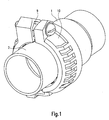
- Fig. 1 shows a plastic tube with a plug-in sleeve 1, in which a further plastic tube is inserted, which comprises a spigot 2.
- the socket 1 comprises a bead 10, which projecting annular bead over the circumference of the socket 1.
- the pipe connecting device comprises two half-shell-shaped holding elements 3, 4. These have, as is apparent from Fig. 3, a substantially U-shaped cross-section.
- a rear wall 11 serves to rest against the bead 10 of the plug-in sleeve 1.
- a bearing surface 5 is formed, which is designed partially cylindrical and abuts against the outer surface of the spigot end 2 when the two holding elements 3, 4 are braced against each other.
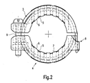
- the two holding elements 3, 4 are connected by means of a snap connection 8 (see FIG. 2). This results in a simple installation. However, it is also possible to provide a joint or the like instead of the snap connection 8.
- the two free ends of the holding elements 3, 4 are braced against each other by means of a screw.
- the bracket 13 can be dimensioned differently.
- An acute angle of the claw element 6, as shown in Fig. 5, is here for safe clawing cheaper than a bracket 13 of 90 °, as shown in Fig. 6.
Abstract
Description
Die Erfindung bezieht sich auf eine Rohrverbindungsvorrichtung gemäß dem Oberbegriff des Hauptanspruchs.The invention relates to a pipe connecting device according to the preamble of the main claim.
Im Einzelnen bezieht sich die Erfindung auf eine Rohrverbindungsvorrichtung, mittels derer Kunststoffrohre verbunden und aneinander fixiert werden, die über eine Steckmuffe verbunden sind. Dabei wird ein Rohrende (Spitzende) in eine Rohrmuffe eingeschoben. Die Abdichtung erfolgt mittels zumindest eines Dichtrings. Eine axiale Fixierung ist durch derartige bekannte Konstruktionen jedoch nicht oder nur in geringerem Maße gegeben.In detail, the invention relates to a pipe connecting device, by means of which plastic pipes are connected and fixed to each other, which are connected via a plug-in sleeve. In this case, a pipe end (spigot end) is inserted into a pipe socket. The sealing takes place by means of at least one sealing ring. An axial fixation is given by such known constructions, but not or only to a lesser extent.
Insbesondere bei Kunststoffabflussrohren ist es somit erforderlich, diese nachträglich gegen unbeabsichtigtes Auseinanderziehen in axialer Richtung zu sichern.In particular, in plastic drain pipes, it is thus necessary to subsequently secure against unintentional pulling in the axial direction.
Der Stand der Technik zeigt bei Druckwasserrohren Lösungen, bei welchen metallische Krallen oder Klammern aufgesetzt werden. Diese Lösungen erfordern jedoch einen relativ großen Platzbedarf und weiterhin sind die Konstruktionen so ausgebildet, dass sie Rohre mit großen Wandstärken voraussetzen.The prior art shows in pressurized water pipes solutions in which metallic claws or clamps are placed. However, these solutions require a relatively large amount of space and further, the structures are designed so that they require pipes with large wall thicknesses.
Demgegenüber sind Kunststoffabflussrohre, insbesondere für den Hausabflussbereich, dünnwandig ausgestaltet und werden üblicherweise unter sehr beengten Platzverhältnissen installiert. Die Verwendung der vorbekannten Rohrverbindungsvorrichtung für diesen Anwendungszweck scheidet somit aus.In contrast, plastic drain pipes, especially for the house drain area, designed thin-walled and are usually installed in very confined spaces. The use of the previously known pipe connection device for this application thus ruled out.
Der Erfindung liegt die Aufgabe zugrunde, eine Rohrverbindungsvorrichtung der eingangs genannten Art zu schaffen, welche bei einfachem Aufbau, einfacher Montage und wirtschaftlicher Herstellbarkeit für dünnwandige Rohre einsetzbar ist und einen nur geringen Platzbedarf benötigt.The invention has for its object to provide a pipe connection device of the type mentioned, which with a simple structure, easy installation and economical manufacturability for thin-walled pipes can be used and requires only a small space requirement.
Erfindungsgemäß wird die Aufgabe durch die Merkmalskombination des Hauptanspruchs gelöst, die Unteransprüche zeigen weitere vorteilhafte Ausgestaltungen der Erfindung.According to the invention the object is achieved by the feature combination of the main claim, the subclaims show further advantageous embodiments of the invention.
Erfindungsgemäß ist somit vorgesehen, dass die Rohrverbindungsvorrichtung zwei Halteelemente aus Kunststoff umfasst, welche so gestaltet sind, dass sie zumindest über eine teilzylindrische Auflagefläche gegen die Außenfläche des Spitzendes anlegbar sind. Zumindest eines der Halteelemente weist dabei zumindest ein radial nach innen ragendes Krallelement auf, welches über die Auflagefläche vorsteht und welches beim Spannen der Rohrverbindungsvorrichtung in die Oberfläche des Spitzendes des Kunststoffrohrs eingedrückt wird.According to the invention it is thus provided that the pipe connecting device comprises two plastic retaining elements, which are designed so that they can be applied against the outer surface of the spigot end at least over a part-cylindrical bearing surface. At least one of the holding elements in this case has at least one radially inwardly projecting claw element, which projects beyond the support surface and which is pressed into the surface of the spigot end of the plastic tube during clamping of the pipe connection device.
Durch die jeweils teilzylindrische Auflagefläche wird sichergestellt, dass das dünnwandige Kunststoffrohr nicht beschädigt wird. Durch das Krallelement ist es jedoch möglich, die Rohrverbindungsvorrichtung so formschlüssig mit dem Spitzende des Kunststoffrohrs zu verbinden bzw. an diesem zu verankern, dass ein unbeabsichtigtes Lösen der Verbindung der beiden Kunststoffrohre verhindert wird.The respective partially cylindrical bearing surface ensures that the thin-walled plastic pipe is not damaged. By Krall element, however, it is possible to connect the pipe connection device so positively to the spigot end of the plastic tube or to anchor it to this that inadvertent release of the connection of the two plastic pipes is prevented.
Die Gestaltung des Krallelements kann erfindungsgemäß so ausgebildet sein, dass dieses an die Wanddicke des Kunststoffrohrs und an dessen Aufbau (beispielsweise bei Mehrschichtrohren) in optimaler Weise angepasst werden kann.The design of the claw element according to the invention can be designed so that it can be adapted to the wall thickness of the plastic pipe and its structure (for example, multilayer pipes) in an optimal manner.
Die beiden erfindungsgemäß vorgesehenen Halteelemente sind einfach und kostengünstig aus Kunststoff herstellbar. Sie können so dimensioniert werden, dass lediglich ein geringer Raumbedarf besteht, so dass die Rohrverbindungsvorrichtung auch in sehr beengten Raumverhältnissen montierbar ist.The two holding elements provided according to the invention are simple and inexpensive to produce from plastic. They can be dimensioned so that only a small space requirement, so that the pipe connection device can be mounted even in very confined spaces.
Die beiden halbschalenförmigen Halteelemente sind bevorzugter Weise an ihren Endbereichen mittels einer Schnappverbindung, mittels einer Gelenkverbindung oder mittels eines flexiblen Elements verbunden bzw. verbindbar. Bei Verwendung des flexiblen Elements ist es auch möglich, die beiden Halteelemente einstückig aus Kunststoff herzustellen und das flexible Element als Verbindungssteg auszuführen.The two half-shell-shaped holding elements are preferably connected or connectable at their end regions by means of a snap connection, by means of a hinge connection or by means of a flexible element. When using the flexible element, it is also possible to produce the two holding elements in one piece from plastic and to carry out the flexible element as a connecting web.
Die beiden freien Enden der Halteelemente können erfindungsgemäß mittels einer Schraube gegeneinander verspannt werden. Es ist jedoch auch möglich, einen Hebelmechanismus oder einen sonstigen Spannmechanismus vorzusehen. Auch hierbei eröffnet sich die Möglichkeit, eine platzsparende und einfach herstellbare Ausgestaltung vorzusehen.The two free ends of the holding elements can be clamped according to the invention by means of a screw against each other. However, it is also possible to provide a lever mechanism or other clamping mechanism. Here, too, opens the possibility to provide a space-saving and easy to manufacture design.
Erfindungsgemäß ist es somit möglich, die Rohrverbindungsvorrichtung an bereits montierten Rohrleitungen auf einfache und leichte Weise anzubringen.According to the invention it is thus possible to attach the pipe connection device to already mounted pipes in a simple and easy way.
Der rückseitige Anschlag der beiden Halteelemente umfasst zumindest einen Teilbereich der Steckmuffe. Da diese üblicherweise mit einem verdickten, flanschartigen oder ringartigen Bereich versehen ist, in welchen die Dichtung eingelegt ist, ergibt sich hierdurch die Möglichkeit, die Steckmuffe formschlüssig zu umgreifen. Ein Verkrallen des Halteelements mit der Steckmuffe ist somit nicht erforderlich.The rear stop of the two holding elements comprises at least a portion of the plug-in sleeve. Since this is usually provided with a thickened, flange-like or ring-like area in which the seal is inserted, this results in the possibility of positively engaging the plug-in socket. A clawing of the retaining element with the plug-in sleeve is therefore not required.
Erfindungsgemäß ist vorgesehen, dass das Krallelement in einer axialen Schnittebene einen im Wesentlichen keilförmigen Querschnitt aufweist. Durch diese Weiterentwicklung der Erfindung ist es möglich, den Haltewinkel entsprechend zu dimensionieren und ein sicheres Verkrallen mit der Oberfläche des Rohrs zu gewährleisten.According to the invention, it is provided that the claw element has an essentially wedge-shaped cross section in an axial sectional plane. Through this further development of the invention, it is possible to dimension the bracket accordingly and to ensure a secure clawing with the surface of the tube.
Weiterhin ist es günstig, wenn das Krallelement mit zumindest einer Schneide versehen ist. Diese kann in Form einer scharfen Kante ausgebildet sein, beispielsweise durch eine entsprechende Formtrennung einer Form eines Spritzgusswerkzeuges.Furthermore, it is advantageous if the claw element is provided with at least one cutting edge. This can be designed in the form of a sharp edge, for example by a corresponding shape separation of a mold of an injection molding tool.
Besonders günstig ist es, wenn das Krallelement einstückig mit dem Halteelement verbunden ist. Es ist jedoch auch möglich, dieses aus einem anderen Kunststoffmaterial zu fertigen und/oder mittels eines Zwei-Komponenten-Spritzverfahrens herzustellen.It is particularly favorable if the claw element is connected in one piece with the retaining element. However, it is also possible to manufacture this from a different plastic material and / or produce by means of a two-component injection molding process.
Erfindungsgemäß ist es besonders günstig, wenn sich ein Haltewinkel des Krallelements von > 90° ergibt.According to the invention, it is particularly favorable if a holding angle of the cramping element of> 90 ° results.
Der Werkstoff für die Halteelemente kann in einfacher Weise an den Werkstoff der Rohre angepasst werden, so dass sich günstige Werkstoffpaarungen ergeben. Für Polyolefinrohre (PP, PB, PE) eignen sich beispielsweise Polyamid-Typen mit einem hohen Glasfasergehalt. In günstiger Weise ist ein Sekantenmodul bzw. E-Modul > 10 · Rohrwerkstoff vorgesehen.The material for the holding elements can be easily adapted to the material of the tubes, resulting in favorable material pairings. For polyolefin pipes (PP, PB, PE), for example, polyamide types with a high glass fiber content are suitable. Conveniently, a secant module or modulus> 10 · pipe material is provided.
In einer Weiterbildung der Erfindung kann es günstig sein, eine zusätzliche Verdrehsicherung in Umfangsrichtung vorzusehen. Hierdurch wird eine unbeabsichtigte Verdrehung der Verbindungsvorrichtung verhindert, beispielsweise beim Verspannen der beiden Halteelemente mittels einer Schraube. Die zusätzliche Verdrehsicherung kann beispielsweise durch zusätzliche Krallelemente, welche in Umfangsrichtung wirken, realisiert werden. Die Krallelemente weisen somit Schneiden auf, die achsparallel angeordnet sind.In one embodiment of the invention, it may be advantageous to provide an additional rotation in the circumferential direction. As a result, an unintentional rotation of the connecting device is prevented, for example, during clamping of the two holding elements by means of a screw. The additional anti-rotation can be realized for example by additional claw elements, which act in the circumferential direction. The claw elements thus have cutting, which are arranged axially parallel.
Weiterhin ist es erfindungsgemäß möglich, an den Halteelementen mehrere Krallelemente nebeneinander (um den Umfang verteilt) vorzusehen, die bevorzugterweise zueinander einen Abstand aufweisen. Es ist jedoch auch möglich, in Axialrichtung hintereinander mehrere Krallelemente auszubilden.Furthermore, it is possible according to the invention to provide a plurality of claw elements next to one another (distributed around the circumference) on the holding elements, which preferably have a spacing from one another. However, it is also possible in Axial direction behind one another form several claw elements.
In einer Weiterbildung der Erfindung ist vorgesehen, dass die Rohrverbindungsvorrichtung zusätzlich als Rohrschelle dienen kann. Hierzu können zusätzliche Laschen bzw. Sockel oder sonstige Befestigungselemente vorgesehen sein.In a further development of the invention it is provided that the pipe connection device can additionally serve as a pipe clamp. For this purpose, additional tabs or sockets or other fastening elements may be provided.
Im Folgenden wird die Erfindung anhand eines Ausführungsbeispiels in Verbindung mit der Zeichnung beschrieben. Dabei zeigt:
- Fig. 1
- eine perspektivische Darstellung des Verbindungsbereichs zweier Rohre unter Verwendung eines Ausführungsbeispiels der erfindungsgemäßen Rohrverbindungsvorrichtung,
- Fig. 2
- eine schematische Seitenansicht der in Fig. 1 gezeigten Rohrverbindungsvorrichtung,
- Fig. 3
- eine perspektivische Teil-Ansicht eines erfindungsgemäßen Halteelements,
- Fig. 4
- eine vergrößerte Darstellung der Einzelheit E von Fig. 3,
- Fig. 5
- eine vergrößerte Teil-Ansicht eines Krallelements, eingesetzt in ein Kunststoffrohr, und
- Fig. 6
- eine Variante der in Fig. 5 gezeigten Ausgestaltungsform.
- Fig. 1
- a perspective view of the connection region of two pipes using an embodiment of the pipe connection device according to the invention,
- Fig. 2
- FIG. 2 a schematic side view of the pipe connection device shown in FIG. 1, FIG.
- Fig. 3
- a perspective partial view of a holding element according to the invention,
- Fig. 4
- an enlarged view of the detail E of Fig. 3,
- Fig. 5
- an enlarged partial view of a cramping element, inserted in a plastic tube, and
- Fig. 6
- a variant of the embodiment shown in Fig. 5.
Die Fig. 1 zeigt ein Kunststoffrohr mit einer Steckmuffe 1, in welche ein weiteres Kunststoffrohr eingesteckt ist, welches ein Spitzende 2 umfasst. Die Steckmuffe 1 umfasst eine Sicke 10, welche ringwulstartig über den Umfang der Steckmuffe 1 vorsteht.Fig. 1 shows a plastic tube with a plug-in
Die erfindungsgemäße Rohrverbindungsvorrichtung umfasst zwei halbschalenförmige Halteelemente 3, 4. Diese weisen, wie aus Fig. 3 ersichtlich ist, einen im Wesentlichen U-förmigen Querschnitt auf. Eine Rückwand 11 dient zur Anlage gegen die Sicke 10 der Steckmuffe 1. An der gegenüberliegenden Wandung 12 ist eine Auflagefläche 5 ausgebildet, welche teilzylindrisch ausgestaltet ist und gegen die Außenfläche des Spitzendes 2 anliegt, wenn die beiden Halteelemente 3, 4 gegeneinander verspannt sind.The pipe connecting device according to the invention comprises two half-shell-shaped
Von der Auflagefläche 5 stehen mehrere, am Umfang verteilte zueinander beabstandete Krallelemente 6 vor, die jeweils eine Schneide 7 aufweisen. Die Krallelemente 6 mit den Schneiden 7 sind somit in die Oberfläche des Spitzendes 2 des Kunststoffrohres eingepresst, wenn die Rohrverbindungsvorrichtung montiert ist, so wie sich dies aus den Darstellungen der Fig. 5 und 6 ergibt.From the
Die beiden Halteelemente 3, 4 sind mittels einer Schnappverbindung 8 verbunden (siehe Fig. 2). Hierdurch ergibt sich eine einfache Montage. Es ist jedoch auch möglich, anstelle der Schnappverbindung 8 ein Gelenk oder ähnliches vorzusehen.The two holding
Die beiden freien Enden der Halteelemente 3, 4 sind mittels einer Schraube gegeneinander verspannt.The two free ends of the holding
Die Fig. 5 und 6 zeigten jeweils unterschiedliche Krallelemente 6 in der Seitenansicht bzw. im Schnitt und deren Eindringen in den Kunststoff. Es ergibt sich, dass die Krallelemente keilförmig ausgebildet sind und hierdurch jeweils einen Haltewinkel 13 definieren. Die Haltewinkel 13 können unterschiedlich dimensioniert sein. Ein spitzer Winkel des Krallelements 6, wie in Fig. 5 gezeigt, ist hierbei zum sicheren Verkrallen günstiger, als ein Haltewinkel 13 von 90°, so wie dies in Fig. 6 dargestellt ist.5 and 6 each showed
Durch die schräge Auflagefläche 5 ergibt sich bei der Montage eine leichte Verdrehung oder Verkippung des Krallelements 6 und damit ein optimierter Halt. Die Fig. 5 zeigt den verbesserten Halt durch den Haltewinkel 13 größer 90°. In Fig. 6 ist das verbesserte Eindringen dargestellt.Due to the
- 11
- Steckmuffeplug socket
- 22
- Spitzendespigot
- 33
- Halteelementretaining element
- 44
- Halteelementretaining element
- 55
- Auflageflächebearing surface
- 66
- KrallelementKrall element
- 77
- Schneidecutting edge
- 88th
- Schnappverbindungsnap
- 99
- Schraubescrew
- 1010
- SickeBeading
- 1111
- Rückwandrear wall
- 1212
- Wandungwall
- 1313
- Haltewinkelbracket
Claims (15)
Applications Claiming Priority (1)
| Application Number | Priority Date | Filing Date | Title |
|---|---|---|---|
| DE202005019635U DE202005019635U1 (en) | 2005-12-15 | 2005-12-15 | Pipe connecting device |
Publications (2)
| Publication Number | Publication Date |
|---|---|
| EP1798459A1 true EP1798459A1 (en) | 2007-06-20 |
| EP1798459B1 EP1798459B1 (en) | 2009-07-01 |
Family
ID=36012212
Family Applications (1)
| Application Number | Title | Priority Date | Filing Date |
|---|---|---|---|
| EP06024741A Active EP1798459B1 (en) | 2005-12-15 | 2006-11-29 | Pipe connecting device with two half-shell-like retaining elements |
Country Status (4)
| Country | Link |
|---|---|
| EP (1) | EP1798459B1 (en) |
| AT (1) | ATE435394T1 (en) |
| DE (2) | DE202005019635U1 (en) |
| ES (1) | ES2329708T3 (en) |
Cited By (5)
| Publication number | Priority date | Publication date | Assignee | Title |
|---|---|---|---|---|
| DE202017105250U1 (en) | 2017-08-31 | 2017-10-24 | Funke Kunststoffe Gmbh | Tensile pipe connection with clamping ring |
| EP3372192A1 (en) * | 2017-03-10 | 2018-09-12 | Johannes Petrus Michael Grobbee | Dental blank positioning device |
| US10905528B2 (en) | 2016-09-21 | 2021-02-02 | Global Dental Science, LLC | System and method for registering implant orientation directly from a dental impression |
| US10952829B2 (en) | 2016-11-27 | 2021-03-23 | Global Dental Science Llc | Tooth fixturing using machinable matrices |
| US11858083B2 (en) | 2017-03-09 | 2024-01-02 | Global Dental Science, LLC | Dental blank positioning device |
Families Citing this family (8)
| Publication number | Priority date | Publication date | Assignee | Title |
|---|---|---|---|---|
| US20080054636A1 (en) * | 2006-09-01 | 2008-03-06 | Banjo Corporation | Method and apparatus for coupling a removable fluid conduit to an existing fluid conduit |
| DE102009007821A1 (en) | 2009-02-07 | 2010-08-12 | Rehau Ag + Co | Pipe connecting device |
| DK177164B1 (en) * | 2010-02-26 | 2012-04-02 | Bluecher Metal As | Locking bracket and method of holding a sleeve assembly and using such locking bracket |
| DE102010014964A1 (en) | 2010-04-14 | 2011-12-08 | Rehau Ag + Co. | Device for axially fixing a connection between a pipe and a pipe component and a connection comprising such a device, and use of such a device |
| DE102014203145B4 (en) | 2014-02-21 | 2021-03-11 | Poloplast Gmbh & Co. Kg | Pipe connecting device |
| DE102016125325A1 (en) | 2016-12-22 | 2018-06-28 | Rehau Ag + Co | A method of making a pipe joint and pipe for use in such a method |
| DE102018131750A1 (en) | 2018-12-11 | 2020-06-18 | Rehau Ag + Co | Pipe connection, process for their manufacture and pipe |
| DE202018107107U1 (en) | 2018-12-12 | 2020-03-13 | Rehau Ag + Co | Pipe connection arrangement |
Citations (3)
| Publication number | Priority date | Publication date | Assignee | Title |
|---|---|---|---|---|
| US4471979A (en) * | 1982-03-15 | 1984-09-18 | Victaulic Company Of Canada Limited | Quick-connect coupling for thin-walled pipes |
| DE10006029A1 (en) * | 2000-02-10 | 2001-08-30 | Uwe Vieregge | Arrangement for connecting two pipes |
| US20050253380A1 (en) * | 2004-05-14 | 2005-11-17 | Victaulic Company Of America | Deformable mechanical pipe coupling |
-
2005
- 2005-12-15 DE DE202005019635U patent/DE202005019635U1/en not_active Expired - Lifetime
-
2006
- 2006-11-29 ES ES06024741T patent/ES2329708T3/en active Active
- 2006-11-29 AT AT06024741T patent/ATE435394T1/en active
- 2006-11-29 DE DE502006004119T patent/DE502006004119D1/en active Active
- 2006-11-29 EP EP06024741A patent/EP1798459B1/en active Active
Patent Citations (3)
| Publication number | Priority date | Publication date | Assignee | Title |
|---|---|---|---|---|
| US4471979A (en) * | 1982-03-15 | 1984-09-18 | Victaulic Company Of Canada Limited | Quick-connect coupling for thin-walled pipes |
| DE10006029A1 (en) * | 2000-02-10 | 2001-08-30 | Uwe Vieregge | Arrangement for connecting two pipes |
| US20050253380A1 (en) * | 2004-05-14 | 2005-11-17 | Victaulic Company Of America | Deformable mechanical pipe coupling |
Cited By (5)
| Publication number | Priority date | Publication date | Assignee | Title |
|---|---|---|---|---|
| US10905528B2 (en) | 2016-09-21 | 2021-02-02 | Global Dental Science, LLC | System and method for registering implant orientation directly from a dental impression |
| US10952829B2 (en) | 2016-11-27 | 2021-03-23 | Global Dental Science Llc | Tooth fixturing using machinable matrices |
| US11858083B2 (en) | 2017-03-09 | 2024-01-02 | Global Dental Science, LLC | Dental blank positioning device |
| EP3372192A1 (en) * | 2017-03-10 | 2018-09-12 | Johannes Petrus Michael Grobbee | Dental blank positioning device |
| DE202017105250U1 (en) | 2017-08-31 | 2017-10-24 | Funke Kunststoffe Gmbh | Tensile pipe connection with clamping ring |
Also Published As
| Publication number | Publication date |
|---|---|
| EP1798459B1 (en) | 2009-07-01 |
| ES2329708T3 (en) | 2009-11-30 |
| DE202005019635U1 (en) | 2006-02-23 |
| ATE435394T1 (en) | 2009-07-15 |
| DE502006004119D1 (en) | 2009-08-13 |
Similar Documents
| Publication | Publication Date | Title |
|---|---|---|
| EP1798459B1 (en) | Pipe connecting device with two half-shell-like retaining elements | |
| EP2354615B1 (en) | Safety device for a fluid conduit | |
| DE102004032134B4 (en) | plug-in coupling | |
| DE2921568A1 (en) | PLUG-IN CONNECTOR FOR COMPRESSED AIR BRAKE SYSTEM | |
| EP2492569A2 (en) | Muffle connection | |
| DE10261595B4 (en) | pipe connectors | |
| EP1564473B1 (en) | Coupling with clamping ring | |
| WO2013030102A1 (en) | Cutting-ring pre-installation device for threaded pipe connections | |
| EP0319746A1 (en) | Coupling device for two conduits, in particular for fuel conduits | |
| EP1352193A1 (en) | Locking plug-in connection device | |
| WO2001090629A1 (en) | Detachable quick connector with safety clip | |
| EP1484544B1 (en) | Conduit feed-through for the installation of a sanitary tube through a wall | |
| DE202011103941U1 (en) | pipe connectors | |
| DE202022101795U1 (en) | Insertion aid for clamp connectors and clamp connectors for pipes | |
| DE102006013934A1 (en) | Attachment device e.g. for pipe, has tube piece having base at which connecting piece for pipe is formed and at base, connectable nut and clamping element are provided | |
| DE102008063582A1 (en) | Circular pipe clamp, has clamp ring with opening, pipe inserted into area of circumference of opening of ring, and clamping screw exhibiting thread-free shaft section covered over its entire length by flexible element | |
| DE202005020263U1 (en) | Multiple coupling for media lines | |
| DE102014203145B4 (en) | Pipe connecting device | |
| WO2006087056A1 (en) | Device for connection to an end of a corrugated pipe | |
| EP0786618A1 (en) | Connecting element for a branch pipe | |
| EP1921364A1 (en) | Compression fitting for a pipe, in particular heating and/or sanitary pipe | |
| DE10320935B3 (en) | Arrangement used in aircraft construction connects two pipes each having supports with first support regions and second support regions | |
| EP3492796B1 (en) | Connection system for repairing plastic composite pipe systems | |
| DE19813762C1 (en) | Pipe connection for connecting a plastic pipe to a plastic or metal sleeve | |
| DE10219442A1 (en) | connector |
Legal Events
| Date | Code | Title | Description |
|---|---|---|---|
| PUAI | Public reference made under article 153(3) epc to a published international application that has entered the european phase |
Free format text: ORIGINAL CODE: 0009012 |
|
| AK | Designated contracting states |
Kind code of ref document: A1 Designated state(s): AT BE BG CH CY CZ DE DK EE ES FI FR GB GR HU IE IS IT LI LT LU LV MC NL PL PT RO SE SI SK TR |
|
| AX | Request for extension of the european patent |
Extension state: AL BA HR MK YU |
|
| 17P | Request for examination filed |
Effective date: 20070920 |
|
| AKX | Designation fees paid |
Designated state(s): AT CZ DE ES HU IT |
|
| GRAP | Despatch of communication of intention to grant a patent |
Free format text: ORIGINAL CODE: EPIDOSNIGR1 |
|
| GRAS | Grant fee paid |
Free format text: ORIGINAL CODE: EPIDOSNIGR3 |
|
| GRAA | (expected) grant |
Free format text: ORIGINAL CODE: 0009210 |
|
| AK | Designated contracting states |
Kind code of ref document: B1 Designated state(s): AT CZ DE ES HU IT |
|
| REF | Corresponds to: |
Ref document number: 502006004119 Country of ref document: DE Date of ref document: 20090813 Kind code of ref document: P |
|
| REG | Reference to a national code |
Ref country code: ES Ref legal event code: FG2A Ref document number: 2329708 Country of ref document: ES Kind code of ref document: T3 |
|
| REG | Reference to a national code |
Ref country code: HU Ref legal event code: AG4A Ref document number: E006395 Country of ref document: HU |
|
| PLBE | No opposition filed within time limit |
Free format text: ORIGINAL CODE: 0009261 |
|
| STAA | Information on the status of an ep patent application or granted ep patent |
Free format text: STATUS: NO OPPOSITION FILED WITHIN TIME LIMIT |
|
| 26N | No opposition filed |
Effective date: 20100406 |
|
| PGFP | Annual fee paid to national office [announced via postgrant information from national office to epo] |
Ref country code: ES Payment date: 20231215 Year of fee payment: 18 |
|
| PGFP | Annual fee paid to national office [announced via postgrant information from national office to epo] |
Ref country code: IT Payment date: 20231130 Year of fee payment: 18 Ref country code: HU Payment date: 20231129 Year of fee payment: 18 Ref country code: DE Payment date: 20231130 Year of fee payment: 18 Ref country code: CZ Payment date: 20231116 Year of fee payment: 18 Ref country code: AT Payment date: 20231117 Year of fee payment: 18 |