EP1798375A2 - Profil d'aube pour aubes statoriques variables - Google Patents
Profil d'aube pour aubes statoriques variables Download PDFInfo
- Publication number
- EP1798375A2 EP1798375A2 EP06024318A EP06024318A EP1798375A2 EP 1798375 A2 EP1798375 A2 EP 1798375A2 EP 06024318 A EP06024318 A EP 06024318A EP 06024318 A EP06024318 A EP 06024318A EP 1798375 A2 EP1798375 A2 EP 1798375A2
- Authority
- EP
- European Patent Office
- Prior art keywords
- stator
- zone
- hsv
- skeleton line
- line
- Prior art date
- Legal status (The legal status is an assumption and is not a legal conclusion. Google has not performed a legal analysis and makes no representation as to the accuracy of the status listed.)
- Granted
Links
Images


Classifications
-
- F—MECHANICAL ENGINEERING; LIGHTING; HEATING; WEAPONS; BLASTING
- F04—POSITIVE - DISPLACEMENT MACHINES FOR LIQUIDS; PUMPS FOR LIQUIDS OR ELASTIC FLUIDS
- F04D—NON-POSITIVE-DISPLACEMENT PUMPS
- F04D29/00—Details, component parts, or accessories
- F04D29/40—Casings; Connections of working fluid
- F04D29/52—Casings; Connections of working fluid for axial pumps
- F04D29/54—Fluid-guiding means, e.g. diffusers
- F04D29/56—Fluid-guiding means, e.g. diffusers adjustable
- F04D29/563—Fluid-guiding means, e.g. diffusers adjustable specially adapted for elastic fluid pumps
-
- F—MECHANICAL ENGINEERING; LIGHTING; HEATING; WEAPONS; BLASTING
- F01—MACHINES OR ENGINES IN GENERAL; ENGINE PLANTS IN GENERAL; STEAM ENGINES
- F01D—NON-POSITIVE DISPLACEMENT MACHINES OR ENGINES, e.g. STEAM TURBINES
- F01D17/00—Regulating or controlling by varying flow
- F01D17/10—Final actuators
- F01D17/12—Final actuators arranged in stator parts
- F01D17/14—Final actuators arranged in stator parts varying effective cross-sectional area of nozzles or guide conduits
- F01D17/16—Final actuators arranged in stator parts varying effective cross-sectional area of nozzles or guide conduits by means of nozzle vanes
- F01D17/165—Final actuators arranged in stator parts varying effective cross-sectional area of nozzles or guide conduits by means of nozzle vanes for radial flow, i.e. the vanes turning around axes which are essentially parallel to the rotor centre line
-
- F—MECHANICAL ENGINEERING; LIGHTING; HEATING; WEAPONS; BLASTING
- F01—MACHINES OR ENGINES IN GENERAL; ENGINE PLANTS IN GENERAL; STEAM ENGINES
- F01D—NON-POSITIVE DISPLACEMENT MACHINES OR ENGINES, e.g. STEAM TURBINES
- F01D5/00—Blades; Blade-carrying members; Heating, heat-insulating, cooling or antivibration means on the blades or the members
- F01D5/12—Blades
- F01D5/14—Form or construction
- F01D5/141—Shape, i.e. outer, aerodynamic form
-
- F—MECHANICAL ENGINEERING; LIGHTING; HEATING; WEAPONS; BLASTING
- F04—POSITIVE - DISPLACEMENT MACHINES FOR LIQUIDS; PUMPS FOR LIQUIDS OR ELASTIC FLUIDS
- F04D—NON-POSITIVE-DISPLACEMENT PUMPS
- F04D29/00—Details, component parts, or accessories
- F04D29/40—Casings; Connections of working fluid
- F04D29/52—Casings; Connections of working fluid for axial pumps
- F04D29/54—Fluid-guiding means, e.g. diffusers
- F04D29/541—Specially adapted for elastic fluid pumps
- F04D29/542—Bladed diffusers
- F04D29/544—Blade shapes
-
- F—MECHANICAL ENGINEERING; LIGHTING; HEATING; WEAPONS; BLASTING
- F05—INDEXING SCHEMES RELATING TO ENGINES OR PUMPS IN VARIOUS SUBCLASSES OF CLASSES F01-F04
- F05D—INDEXING SCHEME FOR ASPECTS RELATING TO NON-POSITIVE-DISPLACEMENT MACHINES OR ENGINES, GAS-TURBINES OR JET-PROPULSION PLANTS
- F05D2240/00—Components
- F05D2240/20—Rotors
- F05D2240/30—Characteristics of rotor blades, i.e. of any element transforming dynamic fluid energy to or from rotational energy and being attached to a rotor
- F05D2240/301—Cross-sectional characteristics
-
- F—MECHANICAL ENGINEERING; LIGHTING; HEATING; WEAPONS; BLASTING
- F05—INDEXING SCHEMES RELATING TO ENGINES OR PUMPS IN VARIOUS SUBCLASSES OF CLASSES F01-F04
- F05D—INDEXING SCHEME FOR ASPECTS RELATING TO NON-POSITIVE-DISPLACEMENT MACHINES OR ENGINES, GAS-TURBINES OR JET-PROPULSION PLANTS
- F05D2250/00—Geometry
- F05D2250/10—Two-dimensional
- F05D2250/14—Two-dimensional elliptical
-
- F—MECHANICAL ENGINEERING; LIGHTING; HEATING; WEAPONS; BLASTING
- F05—INDEXING SCHEMES RELATING TO ENGINES OR PUMPS IN VARIOUS SUBCLASSES OF CLASSES F01-F04
- F05D—INDEXING SCHEME FOR ASPECTS RELATING TO NON-POSITIVE-DISPLACEMENT MACHINES OR ENGINES, GAS-TURBINES OR JET-PROPULSION PLANTS
- F05D2250/00—Geometry
- F05D2250/70—Shape
- F05D2250/74—Shape given by a set or table of xyz-coordinates
-
- Y—GENERAL TAGGING OF NEW TECHNOLOGICAL DEVELOPMENTS; GENERAL TAGGING OF CROSS-SECTIONAL TECHNOLOGIES SPANNING OVER SEVERAL SECTIONS OF THE IPC; TECHNICAL SUBJECTS COVERED BY FORMER USPC CROSS-REFERENCE ART COLLECTIONS [XRACs] AND DIGESTS
- Y10—TECHNICAL SUBJECTS COVERED BY FORMER USPC
- Y10S—TECHNICAL SUBJECTS COVERED BY FORMER USPC CROSS-REFERENCE ART COLLECTIONS [XRACs] AND DIGESTS
- Y10S416/00—Fluid reaction surfaces, i.e. impellers
- Y10S416/02—Formulas of curves
Definitions
- the present invention relates to variable stator blades of fluid flow machines such as fans, compressors, pumps, and fans in the axial, semi-axial, or even radial form.
- the working medium can be gaseous or liquid.
- the invention relates to at least one adjustable stator blade, possibly also an adjustable Vorleitrad, a fluid flow machine.
- the blading in question is within a housing, which limits the flow through at least one rotor and a stator with a fluid to the outside.
- a rotor comprises a plurality of rotor blades attached to a rotating shaft and supplies energy to the working fluid
- a stator consists of a plurality of stator blades usually mounted in the housing.
- the aerodynamic load capacity and the efficiency of fluid flow machines is limited in particular by the growth and separation of boundary layers in the region of the radial gap between the blading and the housing or hub, which is structurally necessary at the annular channel edge.
- Rotary adjustable stators in particular, which are characterized by the necessary free cuts in front of and behind the rotary spindle, have a pronounced radial gap and cause considerable flow losses.
- turntables as large as possible are usually provided at the inner and outer ends of the adjusting stators in order to keep the extent of the cutouts in the flow direction small.
- the turntables are arranged so that they are located in the critically classified profile leading edge zone of the blade edge cuts.
- FIG. 1 shows a schematic representation of two blade configurations according to the prior art in the meridian plane given by the radial direction r and the axial direction x.
- the presentation is limited to a mounted in hub as housing variable stator, a storage solely in housing or hub with a full radial gap at the other end of the blade but in some cases also occurs.
- the blade On the left side of the picture, a conventional variable stator without variation of the skeleton line type is shown.
- the blade consists of only one block (ZO) in which the type of skeleton line is given according to uniform rules.
- ZO the type of skeleton line is given according to uniform rules.
- This category includes the so-called CDA (controlled diffusion aerofoils) US4431376 , From an aerodynamic point of view, the CDA aims for a moderate profile frontload.
- the present invention relates to stators, which are rotatably mounted on at least one blade end and can be adjusted via a spindle about a fixed axis of rotation. As in all representations shown here, the inflow of the relevant row of blades takes place, as indicated by the thick arrow, from left to right.
- the present invention has for its object to provide an adjustable stator blade of the type mentioned, which achieves a very effective influencing the edge flow through targeted and problematic, block-wise definition of the profile skeleton lines along the blade height while avoiding the prior art.
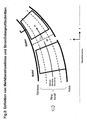
- FIG. 2 gives a precise definition of the meridional flow lines and the streamline profile sections.
- the middle meridional flow line is formed by the geometric center of the ring channel. If one establishes a normal at each location of the middle streamline, one obtains the course of the ring channel width W along the flow path and, on the other hand, a number of normals with whose help further meridional flow lines result with the same relative subdivision in the direction of the channel height.
- the intersection of a meridional streamline with a blade results in a streamline profile intersection.
- FIG. 3a shows the invention adjustable stator blade with storage in housing and hub "SGN" in the meridian plane determined by the axial coordinate x and the radial coordinate r.
- the blade edge zones Z1 and Z2, the transition zones T1 and T2 and the blade central zone Z0 are particularly marked and limited in each case by meridional flow lines as defined in FIG.
- Each of the five bucket zones is assigned a subset WZ1, WT1, WZ0, WT2, WZ2, which is measured in the direction of the channel width W.
- 3b and 3c show the stator blade according to the invention with mounting in the housing "SG” and the stator blade according to the invention with mounting in the hub "SN”.
- FIG. 4 shows the definition of the altitude aspect ratio, which is decisive for the determination of the respective zone widths.
- the middle streamline first gives the position for the determination of the total blade height H when halving the distance between the leading and trailing edges (point G).
- the height H is determined along a straight line at point G perpendicular to the middle streamline.
- five flow lines are specified at 10%, 30%, 50%, 70% and 90% of the channel width W (SL10, SL30, SL50, SL70, SL90), along which the respective chord length L is to be determined.
- the definition of L is shown for any meridian flow area (um level) in the upper left half of the picture.
- the chord length resulting at xy% of the channel width is denoted by LSLxy here and in the formulas of FIG.
- FIG. 5 shows the definition of the rotational axis position, which is co-determining for the invention according to the invention provided profile skeleton line type PR.
- the picture shows a schematic of the streamline section through the adjustable stator blade at 5% and 95% channel width, respectively. Shown is the puncture point of the axis of rotation in the plane of the streamline section, point D. This point does not necessarily have to lie within the profile, as shown here.
- the entire chord length is L. Determined by the perpendicular Lot of the point D on the chord, one obtains the measured distance d of the axis of rotation in the same direction from the front edge.
- the respective skeleton line type is determined in relative representation with the help of the related inclination angle ⁇ * and the related run length s *, see Fig.6a.
- the picture shows a streamlined section of the blade on a meridian flow surface (u-m plane).
- the inclination angle ⁇ P and the run length sP covered up to this point are determined in all points of the skeleton line.
- the inclination angles at leading and trailing edges ⁇ 1 and ⁇ 2 as well as the total running length of the skeleton line S are used. The following applies: ⁇ * ⁇ ⁇ 1 - ⁇ P / ( ⁇ ⁇ 1 - ⁇ ⁇ 2 ) and s * sP / S ,
- FIG. 6b shows in the known relative representation the definition of the skeleton line type "PM".
- Skeleton lines according to the invention are located above a boundary line. Skeleton lines in the exclusion area below and on the boundary line are not according to the invention.
- Skeleton line courses according to the invention are located below the continuous upper limit line and run over the lower limit line given in a specific interval. Skeleton lines in the exclusion area above and on the upper boundary line are not according to the invention. Skeleton line courses below or on the lower boundary line are also not according to the invention.
- FIGS. 6c and 6d a skeleton line distribution which can be provided according to the invention for the blade edge block is shown.
- an edge flow control is achieved, which can increase the efficiency of each stage by about 1% with the same stability.
- a reduction in the number of blades of up to 20% is possible.
- the inventive concept is applicable to different types of turbomachines and, depending on the degree of utilization of the concept, leads to reductions in costs and weight for the turbomachine of 2% to 10%.
Applications Claiming Priority (1)
| Application Number | Priority Date | Filing Date | Title |
|---|---|---|---|
| DE102005060699A DE102005060699A1 (de) | 2005-12-19 | 2005-12-19 | Strömungsarbeitsmaschine mit Verstellstator |
Publications (3)
| Publication Number | Publication Date |
|---|---|
| EP1798375A2 true EP1798375A2 (fr) | 2007-06-20 |
| EP1798375A3 EP1798375A3 (fr) | 2008-10-29 |
| EP1798375B1 EP1798375B1 (fr) | 2011-03-02 |
Family
ID=37905790
Family Applications (1)
| Application Number | Title | Priority Date | Filing Date |
|---|---|---|---|
| EP06024318A Expired - Fee Related EP1798375B1 (fr) | 2005-12-19 | 2006-11-23 | Profil d'aube pour aubes statoriques variables |
Country Status (3)
| Country | Link |
|---|---|
| US (1) | US7416382B2 (fr) |
| EP (1) | EP1798375B1 (fr) |
| DE (2) | DE102005060699A1 (fr) |
Families Citing this family (15)
| Publication number | Priority date | Publication date | Assignee | Title |
|---|---|---|---|---|
| DE102005040574A1 (de) * | 2005-08-26 | 2007-03-15 | Rolls-Royce Deutschland Ltd & Co Kg | Spaltkontrollvorrichtung für eine Gasturbine |
| DE102006055869A1 (de) * | 2006-11-23 | 2008-05-29 | Rolls-Royce Deutschland Ltd & Co Kg | Schaufelblattdesign für die Lauf- und Leitschaufeln einer Turbomaschine |
| WO2012090269A1 (fr) * | 2010-12-27 | 2012-07-05 | 三菱重工業株式会社 | Corps d'aube et machine rotative |
| US8834104B2 (en) | 2010-06-25 | 2014-09-16 | Honeywell International Inc. | Vanes for directing exhaust to a turbine wheel |
| DE102010027588A1 (de) * | 2010-07-19 | 2012-01-19 | Rolls-Royce Deutschland Ltd & Co Kg | Fan-Nachleitradschaufel eines Turbofantriebwerks |
| JP5608062B2 (ja) * | 2010-12-10 | 2014-10-15 | 株式会社日立製作所 | 遠心型ターボ機械 |
| JP6468414B2 (ja) * | 2014-08-12 | 2019-02-13 | 株式会社Ihi | 圧縮機静翼、軸流圧縮機、及びガスタービン |
| US9995166B2 (en) * | 2014-11-21 | 2018-06-12 | General Electric Company | Turbomachine including a vane and method of assembling such turbomachine |
| US9845684B2 (en) * | 2014-11-25 | 2017-12-19 | Pratt & Whitney Canada Corp. | Airfoil with stepped spanwise thickness distribution |
| WO2017168646A1 (fr) * | 2016-03-30 | 2017-10-05 | 三菱重工業株式会社 | Turbocompresseur à géométrie variable |
| DE102016115868A1 (de) * | 2016-08-26 | 2018-03-01 | Rolls-Royce Deutschland Ltd & Co Kg | Strömungsarbeitsmaschine mit hohem Ausnutzungsgrad |
| CN106593943B (zh) * | 2016-12-06 | 2019-01-04 | 大连理工大学 | 一种基于中间线控制的核主泵流道成型方法 |
| IT202000005146A1 (it) * | 2020-03-11 | 2021-09-11 | Ge Avio Srl | Motore a turbina con profilo aerodinamico avente alta accelerazione e bassa curva di paletta |
| CN112145409B (zh) * | 2020-08-28 | 2022-04-26 | 江苏大学 | 一种泵入口翼板非均匀来流抑制装置 |
| CN114109893B (zh) * | 2022-01-27 | 2022-06-21 | 中国航发上海商用航空发动机制造有限责任公司 | 压气机叶片的造型方法以及压气机叶片 |
Citations (6)
| Publication number | Priority date | Publication date | Assignee | Title |
|---|---|---|---|---|
| EP0533319A1 (fr) | 1991-09-17 | 1993-03-24 | ROLLS-ROYCE plc | Profils aérodynamiques pour moteurs à turbine à gaz |
| EP0661413A1 (fr) | 1993-12-23 | 1995-07-05 | Mtu Motoren- Und Turbinen-Union MàNchen Gmbh | Grill d'aubes avec bord d'attaque sous la forme de flèche |
| EP1106836A2 (fr) | 1999-12-06 | 2001-06-13 | General Electric Company | Aube de compresseur à double courbure |
| EP1106835A2 (fr) | 1999-12-06 | 2001-06-13 | General Electric Company | Aube de compresseur |
| EP1508669A1 (fr) | 2003-08-19 | 2005-02-23 | Siemens Aktiengesellschaft | Diaphragme pour compresseur et turbine |
| WO2005054633A1 (fr) | 2003-12-05 | 2005-06-16 | Nuovo Pignone Holding S.P.A. | Tuyere variable destinee a une turbine a gaz |
Family Cites Families (8)
| Publication number | Priority date | Publication date | Assignee | Title |
|---|---|---|---|---|
| DE2835349C2 (de) * | 1978-08-11 | 1979-12-20 | Mtu Motoren- Und Turbinen-Union Muenchen Gmbh, 8000 Muenchen | Verstelleitgitter für hochbelastete Verdichter, insbesondere von Gasturbinentriebwerken |
| US5221181A (en) * | 1990-10-24 | 1993-06-22 | Westinghouse Electric Corp. | Stationary turbine blade having diaphragm construction |
| JP3082378B2 (ja) | 1991-12-20 | 2000-08-28 | 株式会社デンソー | 送風ファン |
| US5492446A (en) * | 1994-12-15 | 1996-02-20 | General Electric Company | Self-aligning variable stator vane |
| EP0945625B1 (fr) | 1998-03-23 | 2004-03-03 | SPAL S.r.l. | Ventilateur à courant axial |
| EP0945627B1 (fr) * | 1998-03-23 | 2004-01-02 | SPAL S.r.l. | Ventilateur à courant axial |
| US6129528A (en) * | 1998-07-20 | 2000-10-10 | Nmb Usa Inc. | Axial flow fan having a compact circuit board and impeller blade arrangement |
| US6457938B1 (en) * | 2001-03-30 | 2002-10-01 | General Electric Company | Wide angle guide vane |
-
2005
- 2005-12-19 DE DE102005060699A patent/DE102005060699A1/de not_active Withdrawn
-
2006
- 2006-11-23 DE DE502006008986T patent/DE502006008986D1/de active Active
- 2006-11-23 EP EP06024318A patent/EP1798375B1/fr not_active Expired - Fee Related
- 2006-12-18 US US11/640,404 patent/US7416382B2/en active Active
Patent Citations (6)
| Publication number | Priority date | Publication date | Assignee | Title |
|---|---|---|---|---|
| EP0533319A1 (fr) | 1991-09-17 | 1993-03-24 | ROLLS-ROYCE plc | Profils aérodynamiques pour moteurs à turbine à gaz |
| EP0661413A1 (fr) | 1993-12-23 | 1995-07-05 | Mtu Motoren- Und Turbinen-Union MàNchen Gmbh | Grill d'aubes avec bord d'attaque sous la forme de flèche |
| EP1106836A2 (fr) | 1999-12-06 | 2001-06-13 | General Electric Company | Aube de compresseur à double courbure |
| EP1106835A2 (fr) | 1999-12-06 | 2001-06-13 | General Electric Company | Aube de compresseur |
| EP1508669A1 (fr) | 2003-08-19 | 2005-02-23 | Siemens Aktiengesellschaft | Diaphragme pour compresseur et turbine |
| WO2005054633A1 (fr) | 2003-12-05 | 2005-06-16 | Nuovo Pignone Holding S.P.A. | Tuyere variable destinee a une turbine a gaz |
Non-Patent Citations (1)
| Title |
|---|
| R. F. BEHLKE, JOURNAL OF TURBOMACHINERY, vol. 8, July 1986 (1986-07-01) |
Also Published As
| Publication number | Publication date |
|---|---|
| DE502006008986D1 (de) | 2011-04-14 |
| US7416382B2 (en) | 2008-08-26 |
| EP1798375A3 (fr) | 2008-10-29 |
| US20070140837A1 (en) | 2007-06-21 |
| EP1798375B1 (fr) | 2011-03-02 |
| DE102005060699A1 (de) | 2007-06-21 |
Similar Documents
| Publication | Publication Date | Title |
|---|---|---|
| EP1798375B1 (fr) | Profil d'aube pour aubes statoriques variables | |
| EP1760321A2 (fr) | Pale d'une turbomachine | |
| EP1657401B1 (fr) | Turbomachine comprenant des aubes avec une augmentation de la longueur des chordes du profil dans l'extrémité de l'aube | |
| EP2096260B1 (fr) | Turbomachine comprenant des ensembles rotor ayant un faible angle de déviation du fluide en sortie | |
| EP1632662B1 (fr) | Turbomachine avec soutirage | |
| EP2025945B1 (fr) | Machine de traitement des écoulements dotée d'un creux de paroi de canal de ceinture | |
| EP2463480B1 (fr) | Aube avec profile hybride | |
| EP2275643B1 (fr) | Aube de moteur dotée d'une charge de rebords avant surélevée | |
| EP2151582A2 (fr) | Machine de traitement des écoulements | |
| EP2226510B1 (fr) | Turbo compresseur ou pompe avec injection de fluide pour influencer la couche limite | |
| EP2761137B1 (fr) | Pale d'une rangée de pales de rotor ou de stator pour une turbomachine | |
| EP2913478B1 (fr) | Aubes en tandem d'une turbomachine | |
| EP2947270B3 (fr) | Groupe de série d'aubes | |
| EP1918529A2 (fr) | Turbomachine avec aubes statoriques ajustables | |
| EP1998049A2 (fr) | Aube de machine de travail d'écoulement doté d'une conception à plusieurs profiles | |
| EP2180195A2 (fr) | Turbomachine avec contrôle du jeu des aubes | |
| EP2538024A1 (fr) | Aube dans une turbomachine | |
| DE102009033591A1 (de) | Strömungsarbeitsmaschine mit Schaufelreihengruppe | |
| EP3287640A1 (fr) | Machine à écoulement à haute performance | |
| EP1953340B1 (fr) | Machine de traitement des écoulements et aube de rotor d'une machine de traitement des écoulements |
Legal Events
| Date | Code | Title | Description |
|---|---|---|---|
| PUAI | Public reference made under article 153(3) epc to a published international application that has entered the european phase |
Free format text: ORIGINAL CODE: 0009012 |
|
| AK | Designated contracting states |
Kind code of ref document: A2 Designated state(s): AT BE BG CH CY CZ DE DK EE ES FI FR GB GR HU IE IS IT LI LT LU LV MC NL PL PT RO SE SI SK TR |
|
| AX | Request for extension of the european patent |
Extension state: AL BA HR MK YU |
|
| PUAL | Search report despatched |
Free format text: ORIGINAL CODE: 0009013 |
|
| AK | Designated contracting states |
Kind code of ref document: A3 Designated state(s): AT BE BG CH CY CZ DE DK EE ES FI FR GB GR HU IE IS IT LI LT LU LV MC NL PL PT RO SE SI SK TR |
|
| AX | Request for extension of the european patent |
Extension state: AL BA HR MK RS |
|
| RIC1 | Information provided on ipc code assigned before grant |
Ipc: F04D 29/56 20060101ALI20080925BHEP Ipc: F04D 29/46 20060101ALI20080925BHEP Ipc: F01D 17/16 20060101ALI20080925BHEP Ipc: F01D 5/14 20060101AFI20070417BHEP Ipc: F04D 29/32 20060101ALI20080925BHEP |
|
| 17P | Request for examination filed |
Effective date: 20081118 |
|
| AKX | Designation fees paid |
Designated state(s): DE FR GB |
|
| 17Q | First examination report despatched |
Effective date: 20091009 |
|
| GRAP | Despatch of communication of intention to grant a patent |
Free format text: ORIGINAL CODE: EPIDOSNIGR1 |
|
| GRAS | Grant fee paid |
Free format text: ORIGINAL CODE: EPIDOSNIGR3 |
|
| GRAA | (expected) grant |
Free format text: ORIGINAL CODE: 0009210 |
|
| AK | Designated contracting states |
Kind code of ref document: B1 Designated state(s): DE FR GB |
|
| REG | Reference to a national code |
Ref country code: GB Ref legal event code: FG4D Free format text: NOT ENGLISH |
|
| REF | Corresponds to: |
Ref document number: 502006008986 Country of ref document: DE Date of ref document: 20110414 Kind code of ref document: P |
|
| REG | Reference to a national code |
Ref country code: DE Ref legal event code: R096 Ref document number: 502006008986 Country of ref document: DE Effective date: 20110414 |
|
| PLBE | No opposition filed within time limit |
Free format text: ORIGINAL CODE: 0009261 |
|
| STAA | Information on the status of an ep patent application or granted ep patent |
Free format text: STATUS: NO OPPOSITION FILED WITHIN TIME LIMIT |
|
| 26N | No opposition filed |
Effective date: 20111205 |
|
| REG | Reference to a national code |
Ref country code: DE Ref legal event code: R097 Ref document number: 502006008986 Country of ref document: DE Effective date: 20111205 |
|
| REG | Reference to a national code |
Ref country code: FR Ref legal event code: PLFP Year of fee payment: 10 |
|
| REG | Reference to a national code |
Ref country code: FR Ref legal event code: PLFP Year of fee payment: 11 |
|
| REG | Reference to a national code |
Ref country code: FR Ref legal event code: PLFP Year of fee payment: 12 |
|
| PGFP | Annual fee paid to national office [announced via postgrant information from national office to epo] |
Ref country code: DE Payment date: 20191127 Year of fee payment: 14 |
|
| PGFP | Annual fee paid to national office [announced via postgrant information from national office to epo] |
Ref country code: FR Payment date: 20191125 Year of fee payment: 14 |
|
| PGFP | Annual fee paid to national office [announced via postgrant information from national office to epo] |
Ref country code: GB Payment date: 20191127 Year of fee payment: 14 |
|
| REG | Reference to a national code |
Ref country code: DE Ref legal event code: R119 Ref document number: 502006008986 Country of ref document: DE |
|
| GBPC | Gb: european patent ceased through non-payment of renewal fee |
Effective date: 20201123 |
|
| PG25 | Lapsed in a contracting state [announced via postgrant information from national office to epo] |
Ref country code: FR Free format text: LAPSE BECAUSE OF NON-PAYMENT OF DUE FEES Effective date: 20201130 |
|
| PG25 | Lapsed in a contracting state [announced via postgrant information from national office to epo] |
Ref country code: GB Free format text: LAPSE BECAUSE OF NON-PAYMENT OF DUE FEES Effective date: 20201123 Ref country code: DE Free format text: LAPSE BECAUSE OF NON-PAYMENT OF DUE FEES Effective date: 20210601 |