EP1798358A2 - Mounting element for attaching insulation boards to a subsurface - Google Patents
Mounting element for attaching insulation boards to a subsurface Download PDFInfo
- Publication number
- EP1798358A2 EP1798358A2 EP06125291A EP06125291A EP1798358A2 EP 1798358 A2 EP1798358 A2 EP 1798358A2 EP 06125291 A EP06125291 A EP 06125291A EP 06125291 A EP06125291 A EP 06125291A EP 1798358 A2 EP1798358 A2 EP 1798358A2
- Authority
- EP
- European Patent Office
- Prior art keywords
- segment sleeve
- fastening element
- segments
- dowel shaft
- element according
- Prior art date
- Legal status (The legal status is an assumption and is not a legal conclusion. Google has not performed a legal analysis and makes no representation as to the accuracy of the status listed.)
- Granted
Links
- 238000009413 insulation Methods 0.000 title claims abstract description 30
- 238000004873 anchoring Methods 0.000 claims abstract description 4
- 239000000758 substrate Substances 0.000 claims description 15
- 239000011810 insulating material Substances 0.000 description 9
- 238000006073 displacement reaction Methods 0.000 description 5
- 239000004033 plastic Substances 0.000 description 5
- 229920003023 plastic Polymers 0.000 description 5
- 239000012774 insulation material Substances 0.000 description 4
- 239000000463 material Substances 0.000 description 4
- 239000002131 composite material Substances 0.000 description 2
- 239000011152 fibreglass Substances 0.000 description 2
- 239000002184 metal Substances 0.000 description 2
- 238000000034 method Methods 0.000 description 2
- 239000000853 adhesive Substances 0.000 description 1
- 230000001070 adhesive effect Effects 0.000 description 1
- 230000004323 axial length Effects 0.000 description 1
- 230000015572 biosynthetic process Effects 0.000 description 1
- 150000001875 compounds Chemical class 0.000 description 1
- 238000011161 development Methods 0.000 description 1
- 230000018109 developmental process Effects 0.000 description 1
- 238000005538 encapsulation Methods 0.000 description 1
- 230000001788 irregular Effects 0.000 description 1
- 238000000465 moulding Methods 0.000 description 1
- 238000000926 separation method Methods 0.000 description 1
- 125000006850 spacer group Chemical group 0.000 description 1
Images

Classifications
-
- E—FIXED CONSTRUCTIONS
- E04—BUILDING
- E04D—ROOF COVERINGS; SKY-LIGHTS; GUTTERS; ROOF-WORKING TOOLS
- E04D3/00—Roof covering by making use of flat or curved slabs or stiff sheets
- E04D3/36—Connecting; Fastening
- E04D3/3601—Connecting; Fastening of roof covering supported by the roof structure with interposition of a insulating layer
- E04D3/3603—Connecting; Fastening of roof covering supported by the roof structure with interposition of a insulating layer the fastening means being screws or nails
-
- E—FIXED CONSTRUCTIONS
- E04—BUILDING
- E04B—GENERAL BUILDING CONSTRUCTIONS; WALLS, e.g. PARTITIONS; ROOFS; FLOORS; CEILINGS; INSULATION OR OTHER PROTECTION OF BUILDINGS
- E04B1/00—Constructions in general; Structures which are not restricted either to walls, e.g. partitions, or floors or ceilings or roofs
- E04B1/62—Insulation or other protection; Elements or use of specified material therefor
- E04B1/74—Heat, sound or noise insulation, absorption, or reflection; Other building methods affording favourable thermal or acoustical conditions, e.g. accumulating of heat within walls
- E04B1/76—Heat, sound or noise insulation, absorption, or reflection; Other building methods affording favourable thermal or acoustical conditions, e.g. accumulating of heat within walls specifically with respect to heat only
- E04B1/762—Exterior insulation of exterior walls
- E04B1/7629—Details of the mechanical connection of the insulation to the wall
-
- E—FIXED CONSTRUCTIONS
- E04—BUILDING
- E04F—FINISHING WORK ON BUILDINGS, e.g. STAIRS, FLOORS
- E04F13/00—Coverings or linings, e.g. for walls or ceilings
- E04F13/07—Coverings or linings, e.g. for walls or ceilings composed of covering or lining elements; Sub-structures therefor; Fastening means therefor
- E04F13/08—Coverings or linings, e.g. for walls or ceilings composed of covering or lining elements; Sub-structures therefor; Fastening means therefor composed of a plurality of similar covering or lining elements
- E04F13/0801—Separate fastening elements
- E04F13/0832—Separate fastening elements without load-supporting elongated furring elements between wall and covering elements
- E04F13/0833—Separate fastening elements without load-supporting elongated furring elements between wall and covering elements not adjustable
- E04F13/0835—Separate fastening elements without load-supporting elongated furring elements between wall and covering elements not adjustable the fastening elements extending into the back side of the covering elements
-
- F—MECHANICAL ENGINEERING; LIGHTING; HEATING; WEAPONS; BLASTING
- F16—ENGINEERING ELEMENTS AND UNITS; GENERAL MEASURES FOR PRODUCING AND MAINTAINING EFFECTIVE FUNCTIONING OF MACHINES OR INSTALLATIONS; THERMAL INSULATION IN GENERAL
- F16B—DEVICES FOR FASTENING OR SECURING CONSTRUCTIONAL ELEMENTS OR MACHINE PARTS TOGETHER, e.g. NAILS, BOLTS, CIRCLIPS, CLAMPS, CLIPS OR WEDGES; JOINTS OR JOINTING
- F16B13/00—Dowels or other devices fastened in walls or the like by inserting them in holes made therein for that purpose
- F16B13/04—Dowels or other devices fastened in walls or the like by inserting them in holes made therein for that purpose with parts gripping in the hole or behind the reverse side of the wall after inserting from the front
- F16B13/08—Dowels or other devices fastened in walls or the like by inserting them in holes made therein for that purpose with parts gripping in the hole or behind the reverse side of the wall after inserting from the front with separate or non-separate gripping parts moved into their final position in relation to the body of the device without further manual operation
- F16B13/085—Dowels or other devices fastened in walls or the like by inserting them in holes made therein for that purpose with parts gripping in the hole or behind the reverse side of the wall after inserting from the front with separate or non-separate gripping parts moved into their final position in relation to the body of the device without further manual operation with a drive-nail deflected by an inclined surface in the dowel body
-
- F—MECHANICAL ENGINEERING; LIGHTING; HEATING; WEAPONS; BLASTING
- F16—ENGINEERING ELEMENTS AND UNITS; GENERAL MEASURES FOR PRODUCING AND MAINTAINING EFFECTIVE FUNCTIONING OF MACHINES OR INSTALLATIONS; THERMAL INSULATION IN GENERAL
- F16B—DEVICES FOR FASTENING OR SECURING CONSTRUCTIONAL ELEMENTS OR MACHINE PARTS TOGETHER, e.g. NAILS, BOLTS, CIRCLIPS, CLAMPS, CLIPS OR WEDGES; JOINTS OR JOINTING
- F16B13/00—Dowels or other devices fastened in walls or the like by inserting them in holes made therein for that purpose
- F16B13/12—Separate metal or non-separate or non-metal dowel sleeves fastened by inserting the screw, nail or the like
- F16B13/124—Separate metal or non-separate or non-metal dowel sleeves fastened by inserting the screw, nail or the like fastened by inserting a threaded element, e.g. screw or bolt
Definitions
- a disadvantage of the known solution is that the pressure plate comes to rest on the surface of the insulation board and the subsequent plastering of the insulation board an irregular appearance can arise.
- any hollow layers between the insulation board and the substrate deflections of the insulation board may occur, which may possibly lead to the breaking of the insulation board.
- the segments on the outside of a roof-shaped outer contour, which extends axially in the direction of the longitudinal axis. Due to the cutting-like or thorn-like configuration of the segments, these easily penetrate into the insulating panel to be fastened.
- the segments of the segment sleeve are releasably connected to each other via a weld line.
- This weld line which forms a predetermined breaking point for the segment sleeve, is formed for example by a tapering of the material thickness during the formation of the segment sleeve.
- the Bindenaht z. B. generated by encapsulation of a correspondingly shaped molding. In plastic engineering, such welds are also called webbed.
- each segment 32 has a straight and flat inner contour 39.
- the segments 32 also have on their outer side a roof-shaped outer contour which extends axially in the direction of the longitudinal axis 12.
- the encircling annular body 38 is provided, which serves as a contact surface for the screw head 18 of the screw 17 and the segments 32 at the second end 35 of the segment sleeve 31 during spreading over a flexurally elastic compound holds together and to limit the axial Versetzweges the segment sleeve 31 serves as a stop when it comes into contact with the second end 23 of the dowel shaft 21.
- FIG. 5 shows an alternative to the deflection means 26 shown in FIGS. 1 and 2.
- the deflection means 46 at the second end 43 of the dowel shaft 41 is formed as a radially projecting from the dowel sleeve 41 collar portion 47 which is formed from the second end 43 in the direction of the first end of the dowel sleeve 41 conically increasing.
- the included by the conical shape of the collar portion 47 and the longitudinal axis 12 angle W is about 40 °.
Abstract
Description
Die Erfindung betrifft ein Befestigungselement für die Befestigung von Dämmstoffplatten an einem Untergrund, der im Oberbegriff des Patentanspruchs 1 genannten Art.The invention relates to a fastener for the attachment of insulation boards to a substrate, referred to in the preamble of claim 1. Art.
Zur Befestigung von Dämmstoffplatten, beispielsweise bei einem Wärmedämm-Verbundsystems, an einer Unterkonstruktion, wie z. B. an einer Wand, ist beispielsweise aus der
Nachteilig an der bekannten Lösung ist, dass der Druckteller an der Oberfläche der Dämmstoffplatte zu liegen kommt und beim anschliessenden Verputzen der Dämmstoffplatte ein unregelmässiges Erscheinungsbild entstehen kann. Zudem können bei allfälligen Hohllagen zwischen der Dämmstoffplatte und dem Untergrund Durchbiegungen der Dämmstoffplatte auftreten, die unter Umständen zum Brechen der Dämmstoffplatte führen können.A disadvantage of the known solution is that the pressure plate comes to rest on the surface of the insulation board and the subsequent plastering of the insulation board an irregular appearance can arise. In addition, in any hollow layers between the insulation board and the substrate deflections of the insulation board may occur, which may possibly lead to the breaking of the insulation board.
Aus der
Nachteilig an der bekannten Lösung ist, dass durch das Komprimieren des Dämmstoffes dessen Rohdichte und damit die Dämmeigenschaften des Dämmstoffes verändert werden. Zudem können bei allfälligen Hohllagen zwischen dem Dämmstoff und dem Untergrund Durchbiegungen der Dämmstoffplatte auftreten, die unter Umständen zum Brechen der Dämmstoffplatte führen können.A disadvantage of the known solution is that the bulk density and thus the insulating properties of the insulating material are changed by compressing the insulating material. In addition, in any hollow layers between the insulating material and the substrate deflections of the insulation board may occur, which may possibly lead to breaking the insulation board.
Aufgabe der Erfindung ist es, ein Befestigungselement für die Befestigung von Dämmstoffplatten an einem Untergrund zu schaffen, das eine sichere Befestigung der Dämmstoffplatte gewährleistet, ohne dabei den Dämmstoff in seinen Eigenschaften zu beeinträchtigen, und das einfach setzbar ist.The object of the invention is to provide a fastener for the attachment of insulation boards to a substrate that ensures a secure attachment of the insulation board, without affecting the insulation material in its properties, and is easy to set.
Die Aufgabe ist durch die Merkmale des unabhängigen Anspruchs gelöst. Vorteilhafte Weiterbildungen sind in den Unteransprüchen dargelegt.The object is solved by the features of the independent claim. Advantageous developments are set forth in the subclaims.
Gemäss der Erfindung ist die Halteeinrichtung aus einer axial in Richtung der Längsachse verschiebbaren Segmenthülse gebildet. Die Segmenthülse beinhaltet mehrere sich axial in Richtung der Längsachse erstreckende, radial angeordnete Segmente, die voneinander separierbar sind. Die Segmenthülse ist mittels des Spreizelementes und eines am zweiten Ende des Dübelschafts angeordneten Umlenkmittels aufspreizbar.According to the invention, the holding device is formed from an axially displaceable in the longitudinal axis of the segment sleeve. The segment sleeve includes a plurality of radially disposed segments extending axially in the direction of the longitudinal axis and separable from one another. The segment sleeve can be expanded by means of the expansion element and a deflecting means arranged at the second end of the dowel shaft.
Das erfindungsgemässe Befestigungselement wird in ein zuvor durch den Dämmstoff in den Untergrund erstelltes Bohrloch eingeführt. Beim Setzen eines Spreiznagels oder beim Verspannen einer Schraube, die beispielsweise das Spreizelement des Befestigungselementes ausbilden, wird die axial verschiebbare Segmenthülse in Setzrichtung beziehungsweise in Richtung des ersten Endes des Dübelschafts verschoben, wobei sich die axial in Richtung der Längsachse erstreckenden, radial angeordneten Segmente über das zweite Ende des Dübelschafts schieben und dabei separiert sowie aufgespreizt werden. Das erfindungsgemässe Befestigungselement wird beim Setzvorgang gleichzeitig im Untergrund und im Dämmstoff verankert, wobei kein spezielles Setzwerkzeug zum Setzen des Befestigungselementes erforderlich ist.The inventive fastener is inserted into a previously created by the insulation in the underground well. When setting a spreader nail or when tightening a screw that form, for example, the expansion element of the fastener, the axially displaceable segment sleeve is displaced in the setting direction or in the direction of the first end of the dowel shaft, wherein extending axially in the direction of the longitudinal axis, radially disposed segments on the push the second end of the dowel shaft and thereby separated and spread open. The fastening element according to the invention is simultaneously anchored in the substrate and in the insulating material during the setting process, wherein no special setting tool is required for setting the fastening element.
Mit einem solchen Befestigungselement sind einzig die Setztiefe im Untergrund sowie der Abstand der Verankerung in der Dämmstoffplatte zum Untergrund vorgegeben, womit mit der gleichen Ausgestaltung eines Befestigungselementes verschiedene Materialstärken beziehungsweise Materialdicken von Dämmstoffplatten am Untergrund fixierbar sind. Weiter findet beim Setzen des Befestigungselementes nur eine Bewegung aller Teile in Setzrichtung, d. h. in Richtung des ersten Endes des Dübelschafts statt, was eine einfache und somit wirtschaftliche Ausgestaltung des Befestigungselementes ermöglicht. Dies ist insbesondere bei einem Massenartikel, wie es das erfindungsgemässe Befestigungselement darstellt, gegenüber aufwändig ausgebildeten Ausführungen ein wesentlicher Vorteil. Das Befestigungselement wird dem Anwender vorteilhaft vormontiert als eine zusammengesetzte Einheit bestehend aus dem Dübelschaft, der Segmenthülse und beispielsweise einer durch die Segmenthülse hindurchgeführte Schraube, die bereits bereichsweise in den Dübelschaft eingreift, zur Verfügung gestellt.With such a fastener only the setting depth in the ground and the distance of the anchor in the insulation board to the ground are given, which with the same configuration of a fastener different material thicknesses or material thicknesses of insulation boards are fixable to the ground. Next, when setting the fastener only a movement of all parts in the setting direction, ie in the direction of the first end of the dowel shaft instead, which allows a simple and thus economic design of the fastener. This is a significant advantage over mass-produced designs, especially in the case of a mass-produced article, such as the fastening element according to the invention. The fastener is advantageously preassembled to the user as a composite unit consisting of the dowel shaft, the segment sleeve and, for example, a guided through the segment sleeve screw already partially engaged in the dowel shaft provided.
Die axiale Länge der Segmente ist für eine ausreichende Haltekraft derselben vorteilhaft derart gewählt, dass die freien Enden der Segmente im aufgespreizten Zustand der Segmente in einer radial zur Längsachse verlaufenden Ebene einen Umfang aufspannen, der dem Umfang eines herkömmlichen Dübeltellers entspricht. Der Aufspreizwinkel der Segmente bezüglich der Längsachse des Befestigungselementes liegt im Bereich von 10° bis 90°.The axial length of the segments is advantageous for a sufficient holding force thereof chosen such that the free ends of the segments in the spread state of the segments in a plane extending radially to the longitudinal axis span a circumference corresponding to the circumference of a conventional anchor plate. The spread angle of the segments with respect to the longitudinal axis of the fastener is in the range of 10 ° to 90 °.
Die Eigenschaften des Dämmstoffs werden im Bereich der Befestigung trotz der sicheren Fixierung der Dämmstoffplatte nicht oder wenn, nur unwesentlich beeinflusst. Die nach dem Setzen des Befestigungselementes gegen aussen verbleibende Öffnung wird beispielsweise durch ein Verschlusselement aus Dämmstoff verschlossen. Mit dem erfindungsgemässen Befestigungselement wird eine Störung der Fassadenoberfläche vermieden, die üblicherweise beim anschliessenden Verputzen der Fassade zu Unregelmässigkeiten des Erscheinungsbildes führt.The properties of the insulating material are in the field of attachment despite the secure fixation of the insulation board not or if, only insignificantly influenced. The remaining after setting the fastener to the outside opening is closed, for example, by a closure element made of insulating material. With the fastening element according to the invention, a disturbance of the facade surface is avoided, which usually leads to irregularities in the appearance during the subsequent plastering of the facade.
Vorzugsweise weist die Segmenthülse ein erstes Ende und ein dem ersten Ende gegenüberliegendes zweites Ende auf, wobei das erste Ende der Segmenthülse dem zweiten Ende des Dübelschafts zugewandt ist, und wobei die die Segmenthülse ausbildenden Segmente an dem ersten Ende der Segmenthülse eine sich radial nach aussen verjüngende Kontur aufweisen. Die Innenkontur der Segmenthülse vergrössert sich in Richtung des zweiten Endes der Segmenthülse beziehungsweise in Richtung der freien Enden der Segmente, so dass Gleitflächen geschaffen werden, die den Aufspreizvorgang der Segmenthülse beim Verspannen sowie den Setzvorgang des Befestigungselementes erleichtern. Zwischen dem zweiten Ende der Segmenthülse und dem Beginn der sich nach aussen verjüngenden Kontur weist jedes Segment für ein leichtes Aufspreizen der Segmenthülse vorteilhaft eine gerade und ebene Innenkontur auf.Preferably, the segment sleeve has a first end and a second end opposite the first end, the first end of the segment sleeve facing the second end of the dowel shaft, and wherein the segment sleeve forming segments at the first end of the segment sleeve a radially outwardly tapering Contour. The inner contour of the segment sleeve increases in the direction of the second end of the segment sleeve or in the direction of the free ends of the segments, so that sliding surfaces are created, which facilitate the Aufspreizvorgang the segment sleeve during clamping and the setting process of the fastener. Between the second end of the segment sleeve and the beginning of the after Outside tapering contour, each segment for easy spreading of the segment sleeve advantageously has a straight and flat inner contour.
Bevorzugt ist ein Ringkörper an dem zweiten Ende der Segmenthülse vorgesehen, der die Segmente auch im aufgespreitzen, voneinander separierten Zustand mittels einer biegeelastischen Verbindung zusammenhält. Gleichzeitig dient der Ringkörper als Angriffsfläche für einen Kopfabschnitt des Spreizelementes beim axialen Verschieben der Segmenthülse. Des Weiteren bildet dieser Ringkörper einen Anschlag für die axiale Verschiebung der Segmenthülse aus und verhindert dabei ein Überspreizen der einzelnen Segmente.Preferably, an annular body is provided at the second end of the segment sleeve, which holds the segments also in the split, separated state by means of a flexurally elastic connection. At the same time, the annular body serves as a contact surface for a head portion of the expansion element during axial displacement of the segment sleeve. Furthermore, this ring body forms a stop for the axial displacement of the segment sleeve and thereby prevents overstretching of the individual segments.
Vorzugsweise weisen die Segmente an deren Aussenseite eine dachförmige Aussenkontur auf, die sich axial in Richtung der Längsachse erstreckt. Durch die schneidenartige beziehungsweise dornartige Ausgestaltung der Segmente dringen diese leicht in die zu befestigende Dämmstoffplatte ein.Preferably, the segments on the outside of a roof-shaped outer contour, which extends axially in the direction of the longitudinal axis. Due to the cutting-like or thorn-like configuration of the segments, these easily penetrate into the insulating panel to be fastened.
Bevorzugt weist die Segmenthülse drei bis zwölf Segmenten auf. Die Anzahl der Segmente ist durch die Materialeigenschaften des Dämmstoffs bestimmt, wobei mehrere Segmente eine gleichmässigere Krafteinleitung gewährleistet. Mit anderen Worten werden bei einer Vielzahl von Segmenten pro Segment geringere Kräfte als bei ein paar wenigen Segmenten in den Dämmstoff eingeleitet.Preferably, the segment sleeve on three to twelve segments. The number of segments is determined by the material properties of the insulating material, with several segments ensuring a more uniform application of force. In other words, smaller forces are introduced into the insulation material per segment for a large number of segments than for a few segments.
Vorzugsweise sind die Segmente der Segmenthülse über eine Bindenaht lösbar miteinander verbunden. Diese Bindenaht, die eine Sollbruchstelle für die Segmenthülse ausbildet, ist beispielsweise durch eine Verjüngung der Materialdicke beim Ausbilden der Segmenthülse ausgebildet. Bei einer Segmenthülse aus Kunststoff wird die Bindenaht z. B. durch ein Umspritzen eines entsprechend ausgebildeten Formteils erzeugt. In der Kunststofftechnik werden solche Bindenähte auch als Schwimmhäute bezeichnet.Preferably, the segments of the segment sleeve are releasably connected to each other via a weld line. This weld line, which forms a predetermined breaking point for the segment sleeve, is formed for example by a tapering of the material thickness during the formation of the segment sleeve. In a plastic segment sleeve, the Bindenaht z. B. generated by encapsulation of a correspondingly shaped molding. In plastic engineering, such welds are also called webbed.
Bevorzugt umfasst das Umlenkmittel am zweiten Ende der Dübelschaft radial von dem Dübelschaft abragende Vorsprünge, die das Separieren und Aufspreizen der Segmente beim axialen Versetzen der Segmenthülse unterstützen. Die Vorsprünge weisen beispielsweise die Form einer drei- oder vierseitigen Pyramide auf. Alternativ sind die Vorsprünge beispielsweise keilförmig ausgebildet, wobei diese vorteilhaft in Richtung des ersten Endes des Dübelschafts zunehmend ausgebildet sind.Preferably, the deflection means at the second end of the dowel shaft radially projecting from the dowel shaft protrusions that support the separation and spreading of the segments in the axial displacement of the segment sleeve. The projections have, for example, the shape of a three- or four-sided pyramid. Alternatively, the projections are for example wedge-shaped, wherein these are advantageously formed increasingly in the direction of the first end of the dowel shaft.
Vorzugsweise entspricht die Anzahl der Vorsprünge der Anzahl der Segmente der Segmenthülse, so dass zum Aufspreizen der Segmenthülse für jedes Segment ein Vorsprung vorgesehen ist.Preferably, the number of projections corresponds to the number of segments of the segment sleeve, so that a projection is provided for spreading the segment sleeve for each segment.
Bevorzugt umfasst das Umlenkmittel am zweiten Ende des Dübelschafts eine Fase, die das Aufspreizen der Segmente beim axialen Versetzen der Segmenthülse unterstützt. Die Fase verjüngt den Durchmesser in Richtung des zweiten Endes des Dübelschafts und weist vorteilhaft einen Winkel zur Längsachse im Bereich von 10° bis 80° auf. In einer weiteren vorteilhaften Ausführungsform umfasst das Umlenkmittel zusätzlich zu der Fase von dem Dübelschaft abragende Vorsprünge, deren Anzahl vorteilhaft der Anzahl der Segmente der Segmenthülse entspricht.Preferably, the deflection means comprises at the second end of the dowel shaft a chamfer, which supports the spreading of the segments in the axial displacement of the segment sleeve. The chamfer tapers the diameter in the direction of the second end of the dowel shaft and advantageously has an angle to the longitudinal axis in the range of 10 ° to 80 °. In a further advantageous embodiment, the deflection means comprises, in addition to the bevel of the dowel shaft protruding projections whose number advantageously corresponds to the number of segments of the segment sleeve.
Alternativ umfasst das Umlenkmittel am zweiten Ende des Dübelschafts vorzugsweise einen radial vom Dübelschaft abragenden Kragenabschnitt, der von dem zweiten Ende des Dübelschafts in Richtung des ersten Endes des Dübelschafts konisch zunehmend ausgebildet ist. Bei dieser Ausführungsform wird das zweite Ende des Dübelschafts nicht geschwächt sondern zusätzlich verstärkt, wobei die konisch zunehmende Ausgestaltung des Kragenabschnitts das Aufspreizen der Segmente beim axialen Versetzen der Segmenthülse vorteilhaft unterstützt. Der vom konischen Verlauf des Kragenabschnitts und der Längsachse eingeschlossene Winkel beträgt vorteilhaft 10° bis 80°. Der Kragenabschnitt am zweiten Ende des Dübelschafts muss nicht zwingend umlaufend ausgebildet sein. Mehrere entlang des Umfangs zueinander beabstandete Teilabschnitte des Kragenabschnitts können ebenfalls das Umlenkmittel ausbilden, wobei die Anzahl der Teilabschnitte der Anzahl der Segmente der Segmenthülse entsprechen kann. Weiter können die einzelnen Teilabschnitte des Kragenabschnitts derart ausgebildet sein, dass zwei Segmente gleichzeitig beim Aufspreizen der Segmenthülse über diese gleiten.Alternatively, the deflection means at the second end of the dowel shaft preferably comprises a radially projecting from the dowel shaft collar portion which is tapered from the second end of the dowel shaft in the direction of the first end of the dowel shaft. In this embodiment, the second end of the dowel shaft is not weakened but additionally reinforced, wherein the conically increasing configuration of the collar portion advantageously supports the spreading of the segments in the axial displacement of the segment sleeve. The included by the conical shape of the collar portion and the longitudinal axis angle is advantageously 10 ° to 80 °. The collar portion at the second end of the dowel shaft does not necessarily have to be circumferentially formed. A plurality of partial sections of the collar section which are spaced apart from one another along the circumference can likewise form the deflection means, wherein the number of partial sections can correspond to the number of segments of the segmented sleeve. Further, the individual sections of the collar portion may be formed such that two segments slide simultaneously during spreading of the segment sleeve over this.
Die einzelnen Teile des erfindungsgemässen Befestigungselementes sind beispielsweise aus einem Kunststoff gefertigt. Beispielsweise wird für eines oder alle Teile ein glasfaserverstärkter Kunststoff verwendet. Weiter können einzelne Teile auch aus Metall gefertigt sein. In einer vorteilhaften Ausführungsform umfasst das Befestigungselement einen Dübelschaft aus einem Kunststoff, eine Segmenthülse aus einem glasfaserverstärkten Kunststoff und ein als Schraube ausgebildetes Spreizelement aus einem Metall.The individual parts of the inventive fastener are made for example of a plastic. For example, one or all parts of a glass fiber reinforced plastic is used. Further, individual parts can also be made of metal. In an advantageous embodiment, the fastening element comprises a dowel shaft made of a plastic, a segment sleeve made of a glass fiber reinforced plastic and a spreading element formed as a screw made of a metal.
Die Erfindung wird nachstehend anhand von Ausführungsbeispielen näher erläutert. Es zeigen:
- Fig. 1
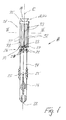
- Eine Seitenansicht eines erfindungsgemässen Befestigungselementes im unverspreizten Zustand;
- Fig. 2
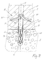
- das in Fig. 1 gezeigte Befestigungselement im verspreizten Zustand;
- Fig. 3
- einen Schnitt durch die Segmenthülse entlang der Linie III-III in Fig. 1;
- Fig. 4
- einen Teilschnitt durch ein Segment der Segmenthülse entlang der Linie IV-IV in Fig. 3;
- Fig. 5
- eine Detailansicht des zweiten Endes des Dübelschafts mit einer Variante der Umlenkeinrichtung; und
- Fig. 6
- eine Detailansicht des zweiten Endes der Dübelschaft mit einer weiteren Variante der Umlenkeinrichtung.
- Fig. 1
- A side view of an inventive fastener in the unexpanded state;
- Fig. 2
- the fastener shown in Figure 1 in the expanded state.
- Fig. 3
- a section through the segment sleeve along the line III-III in Fig. 1;
- Fig. 4
- a partial section through a segment of the segment sleeve along the line IV-IV in Fig. 3;
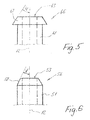
- Fig. 5
- a detailed view of the second end of the dowel shaft with a variant of the deflection device; and
- Fig. 6
- a detailed view of the second end of the dowel shaft with a further variant of the deflection.
Grundsätzlich sind in den Figuren gleiche Teile mit den gleichen Bezugszeichen versehen.Basically, the same parts are provided with the same reference numerals in the figures.
Das in den Fig. 1 und 2 dargestellte Befestigungselement 11 für die Befestigung von Dämmplatten 2 an einem Untergrund 1 umfasst einen sich entlang einer Längsachse 12 erstreckenden Dübelschaft 21, der ein erstes Ende 22 und ein dem ersten Ende 22 gegenüberliegendes zweites Ende 23 aufweist. Im Bereich des ersten Endes 22 ist eine von einer Schraube 17 als Spreizelement 16 aufspreizbare Spreizzone 24 für die Verankerung des Befestigungselementes 11 in dem Untergrund 1 vorgesehen. Weiter weist der Dübelschaft 21 bereichsweise radial zur Längsachse 12 versetzbare Verbreiterungen 25 als Verdrehsicherung des Dübelschafts 21 und damit des Befestigungselementes 11 auf. Am zweiten Ende 23 des Dübelschafts 21 sind als Umlenkmittel 26 eine Fase 27 und mehrere radial vom Dübelschaft 21 abragende, pyramidenförmig ausgebildete Vorsprünge 28 vorgesehen.The
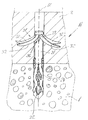
Die Halteeinrichtung für die Fixierung der Dämmplatte 2 am Untergrund 1 ist aus einer axial in Richtung der Längsachse 12 verschiebbaren Segmenthülse 31 gebildet, die acht sich axial in Richtung der Längsachse 12 erstreckende, radial zur Längsachse 12 angeordnete Segmente 32 sowie einen Ringkörper 38 beinhaltet (siehe Fig. 3). Die Segmenthülse 31 ist mittels des Spreizelementes 16 und des am zweiten Ende 23 des Dübelschafts 21 angeordneten Umlenkmittels 26 aufspreizbar. In diesem Ausführungsbeispiel entspricht die Anzahl der Vorsprünge 28 am Dübelschaft 21 der Anzahl der Segmente 32 der Segmenthülse, wobei aufgrund der gewählten Darstellung gemäss der Fig. 1 nur fünf dieser Vorsprünge gezeigt sind.The holding device for fixing the insulation board 2 to the substrate 1 is formed from an axially displaceable in the direction of the
Die Segmenthülse 31 wird nachfolgend anhand der Fig. 3 und 4 beschrieben.The
Die Segmenthülse 31 weist ein erstes Ende 34 und ein dem ersten Ende 34 gegenüberliegendes zweites Ende 35 auf, wobei im zusammengesetzten Zustand des Befestigungselementes 11 das erste Ende 34 der Segmenthülse 31 dem zweiten Ende 23 des Dübelschafts 21 zugewandt ist. Die Segmente 32 sind über eine Bindnaht 33 lösbar miteinander verbunden und von einander separierbar. Die die Segmenthülse 31 ausbildenden Segmente 32 weisen an ihrem freien Ende 36, das dem ersten Ende 34 der Segmenthülse 31 entspricht, eine sich radial nach aussen verjüngende Kontur 37 auf, wodurch sich der Innenquerschnitt der Segmenthülse 31 in Richtung des ersten Endes 34 der Segmenthülse 31 vergrössert. Zwischen dem zweiten Ende 35 der Segmenthülse 31 und dem Beginn der sich radial nach aussen verjüngende Kontur 37 weist jedes Segment 32 eine gerade und ebene Innenkontur 39 auf. Die Segmente 32 weisen zudem an deren Aussenseite eine dachförmige Aussenkontur auf, die sich axial in Richtung der Längsachse 12 erstreckt. An dem zweiten Ende 35 der Segmenthülse 31 ist der umlaufende Ringkörper 38 vorgesehen, der als Angriffsfläche für den Schraubenkopf 18 der Schraube 17 dient und die Segmente 32 am zweiten Ende 35 der Segmenthülse 31 beim Aufspreizen über eine biegeelastische Verbindung zusammenhält sowie zur Begrenzung des axialen Versetzweges der Segmenthülse 31 als Anschlag dient, wenn dieser mit dem zweiten Ende 23 des Dübelschafts 21 in Anlage kommt.The
Nachfolgend wird anhand der Fig. 2 ein Setzvorgang des Befestigungselementes 11 beschrieben.Subsequently, a setting operation of the
Die Dämmstoffplatte 2 wird beispielsweise mit einem Kleber 3 an dem Untergrund 1 vorfixiert. Dann wird durch die Dämmplatte 2 hindurch ein Bohrloch 4 in den Untergrund 1 erstellt und das Befestigungselement 11 im unverspreizten Zustand in dieses eingeführt, bis die Verbreiterungen 25 am Dübelschaft 21 sich mit der Bohrlochwandung 5 verkeilen. Anschliessend wird durch Verspannen der Schraube 17 einerseits die Spreizzone 24 aufgeweitet und andererseits über den Schraubenkopf 18 die Segmenthülse axial in Richtung der Längsachse 12 verschoben, wobei die Segmente 32 der Segmenthülse 31 über die Umlenkmittel 26 aufgespreizt werden, wobei die Bindenähte 33 reissen und die Segmente 32 in die Dämmstoffplatte 2 eindringen. Mit dem Spreizelement 16, hier mit der Schraube 17, wird gleichzeitig in einem Arbeitsschritt das Befestigungselement 11 im Untergrund 1 verankert und die Dämmplatte 2 am Untergrund 1 befestigt.The insulation board 2 is prefixed for example with an adhesive 3 to the substrate 1. Then, through the insulation board 2 through a
In Fig. 5 ist eine Alternative zu dem in der Fig. 1 bzw. 2 dargestellten Umlenkmittel 26 gezeigt. Das Umlenkmittel 46 am zweiten Ende 43 des Dübelschafts 41 ist als radial von der Dübelhülse 41 abragender Kragenabschnitt 47 ausgebildet, der von dem zweiten Ende 43 in Richtung des ersten Endes der Dübelhülse 41 konisch zunehmend ausgebildet ist. Der vom konischen Verlauf des Kragenabschnitts 47 und der Längsachse 12 eingeschlossene Winkel W beträgt etwa 40°.FIG. 5 shows an alternative to the deflection means 26 shown in FIGS. 1 and 2. The deflection means 46 at the
In Fig. 6 ist eine weitere Alternative zu dem in der Fig. 1 bzw. 2 dargestellten Umlenkmittel 26 gezeigt. Das Umlenkmittel 56 am zweiten Ende 53 des Dübelschafts 51 ist als Fase 57 ausgebildet. Der von dem Verlauf der Fase 57 und der Längsachse 12 eingeschlossene Winkel V beträgt etwa 30°.FIG. 6 shows a further alternative to the deflection means 26 shown in FIGS. 1 and 2. The deflection means 56 at the
Claims (10)
Applications Claiming Priority (1)
| Application Number | Priority Date | Filing Date | Title |
|---|---|---|---|
| DE200510000185 DE102005000185A1 (en) | 2005-12-14 | 2005-12-14 | Fastening element for fixing insulation boards to a substrate |
Publications (3)
| Publication Number | Publication Date |
|---|---|
| EP1798358A2 true EP1798358A2 (en) | 2007-06-20 |
| EP1798358A3 EP1798358A3 (en) | 2008-10-08 |
| EP1798358B1 EP1798358B1 (en) | 2018-11-28 |
Family
ID=37745971
Family Applications (1)
| Application Number | Title | Priority Date | Filing Date |
|---|---|---|---|
| EP06125291.2A Not-in-force EP1798358B1 (en) | 2005-12-14 | 2006-12-04 | Mounting element for attaching insulation boards to a subsurface |
Country Status (2)
| Country | Link |
|---|---|
| EP (1) | EP1798358B1 (en) |
| DE (1) | DE102005000185A1 (en) |
Cited By (6)
| Publication number | Priority date | Publication date | Assignee | Title |
|---|---|---|---|---|
| WO2009071168A1 (en) * | 2007-12-06 | 2009-06-11 | Fischerwerke Gmbh & Co. Kg | Insulation holder and method for attaching an insulation plate |
| WO2011040827A1 (en) * | 2009-10-02 | 2011-04-07 | Klimas Wkręt-Met Spółka Z.O.O. | Plug for insulation material |
| EP2372037A1 (en) | 2010-03-22 | 2011-10-05 | Rogger Fasteners AG | Fastening device |
| EP2570682A1 (en) * | 2011-09-13 | 2013-03-20 | Rogger Fasteners AG | Component fixing device |
| EP2581512A3 (en) * | 2011-10-12 | 2014-02-19 | Rolf Kammerer | Plastic anchor for attaching insulation panels to buildings |
| CN113089854A (en) * | 2021-04-21 | 2021-07-09 | 中国十七冶集团有限公司 | Building external wall heat insulation integrated structure and construction method |
Families Citing this family (2)
| Publication number | Priority date | Publication date | Assignee | Title |
|---|---|---|---|---|
| DE202011051809U1 (en) * | 2011-10-28 | 2013-01-30 | Andrè Bürmann | wall anchor |
| CN110206175B (en) * | 2019-06-11 | 2020-12-15 | 甘肃盛宏建筑工程有限责任公司 | Fixing device of wall insulation board |
Citations (3)
| Publication number | Priority date | Publication date | Assignee | Title |
|---|---|---|---|---|
| DE29623122U1 (en) | 1995-09-28 | 1997-11-06 | Ejot Kunststofftech Gmbh | Fastening element for fastening heat-insulating materials |
| EP1318250A2 (en) | 2001-12-05 | 2003-06-11 | EJOT Kunststofftechnik GmbH & Co. KG | Dowel and method for mounting insulating panels |
| EP1691086A1 (en) | 2005-02-09 | 2006-08-16 | Fischerwerke Arthur Fischer GmbH & Co. KG | Insulating material fixing means |
Family Cites Families (3)
| Publication number | Priority date | Publication date | Assignee | Title |
|---|---|---|---|---|
| US3133378A (en) * | 1959-03-12 | 1964-05-19 | Illinois Tool Works | Nail type fasteners |
| DE19833070A1 (en) * | 1998-07-23 | 2000-01-27 | Fischer Artur Werke Gmbh | Expansion anchors made of metal |
| DE10106054A1 (en) * | 2001-02-09 | 2002-08-14 | Jochen Haase | Wall plug for attaching e.g. plasterboard to old masonry has arms at top which are spread when screw is tightened and support board and compensate for unevenness in wall |
-
2005
- 2005-12-14 DE DE200510000185 patent/DE102005000185A1/en not_active Withdrawn
-
2006
- 2006-12-04 EP EP06125291.2A patent/EP1798358B1/en not_active Not-in-force
Patent Citations (3)
| Publication number | Priority date | Publication date | Assignee | Title |
|---|---|---|---|---|
| DE29623122U1 (en) | 1995-09-28 | 1997-11-06 | Ejot Kunststofftech Gmbh | Fastening element for fastening heat-insulating materials |
| EP1318250A2 (en) | 2001-12-05 | 2003-06-11 | EJOT Kunststofftechnik GmbH & Co. KG | Dowel and method for mounting insulating panels |
| EP1691086A1 (en) | 2005-02-09 | 2006-08-16 | Fischerwerke Arthur Fischer GmbH & Co. KG | Insulating material fixing means |
Cited By (8)
| Publication number | Priority date | Publication date | Assignee | Title |
|---|---|---|---|---|
| WO2009071168A1 (en) * | 2007-12-06 | 2009-06-11 | Fischerwerke Gmbh & Co. Kg | Insulation holder and method for attaching an insulation plate |
| WO2011040827A1 (en) * | 2009-10-02 | 2011-04-07 | Klimas Wkręt-Met Spółka Z.O.O. | Plug for insulation material |
| RU2525395C2 (en) * | 2009-10-02 | 2014-08-10 | Климас Вкрэнт-Мэт Спулка З.О.О. | Dowel for insulation material |
| EP2372037A1 (en) | 2010-03-22 | 2011-10-05 | Rogger Fasteners AG | Fastening device |
| EP2570682A1 (en) * | 2011-09-13 | 2013-03-20 | Rogger Fasteners AG | Component fixing device |
| EP2581512A3 (en) * | 2011-10-12 | 2014-02-19 | Rolf Kammerer | Plastic anchor for attaching insulation panels to buildings |
| CN113089854A (en) * | 2021-04-21 | 2021-07-09 | 中国十七冶集团有限公司 | Building external wall heat insulation integrated structure and construction method |
| CN113089854B (en) * | 2021-04-21 | 2022-03-29 | 中国十七冶集团有限公司 | Building external wall heat insulation integrated structure and construction method |
Also Published As
| Publication number | Publication date |
|---|---|
| EP1798358A3 (en) | 2008-10-08 |
| DE102005000185A1 (en) | 2007-06-21 |
| EP1798358B1 (en) | 2018-11-28 |
Similar Documents
| Publication | Publication Date | Title |
|---|---|---|
| EP0356425B1 (en) | Fixing rod | |
| EP1798358B1 (en) | Mounting element for attaching insulation boards to a subsurface | |
| WO2002008615A1 (en) | Undercut anchor element that can be mounted with positive engagement | |
| EP0362550A2 (en) | Impact-flaring plug for anchorage into conically inwardly distended holes | |
| DE2607338A1 (en) | KNOCKING DOWEL WITH EXPANSION SLEEVE AND EXPANSION ELEMENT | |
| EP0426951B1 (en) | Fixing rod | |
| EP2044270B1 (en) | Fastening systems and method for fitting insulating panels | |
| DE3907034A1 (en) | Expansion dowel | |
| EP0731881A1 (en) | Expanding anchor device | |
| DE3831683A1 (en) | Expansion anchor | |
| DE19520130A1 (en) | Form-fit undercut anchor | |
| WO1997032142A1 (en) | Knock-in pin dowel | |
| EP0724085A1 (en) | Fastening anchor with undercut and form-locking action | |
| EP0728882B1 (en) | Fastening element for fastening thick plates on structural components | |
| DE4203831A1 (en) | WEDGE-LIKE WALL BLIND NAIL | |
| EP0843788A1 (en) | Securing component and method of anchoring it | |
| DE3502607A1 (en) | Anchor, in particular load-dependent dowel | |
| DE3022414A1 (en) | Anchoring dowel for light construction materials - consists of cylindrical expansion element with external ribs, locking in slots during expansion | |
| DE1775527A1 (en) | Multipart expansion dowel | |
| DE4113924C2 (en) | Fastener | |
| DE2406207A1 (en) | Anchor bolt for blind hole in low density building material - has radially movable blades to form anchorage | |
| DE19632469C2 (en) | Nail with spreadable legs | |
| DE3640929C2 (en) | Anchor for setting in blind holes | |
| EP0558890B1 (en) | Expansion dowel | |
| EP1205674B1 (en) | Expansion dowel |
Legal Events
| Date | Code | Title | Description |
|---|---|---|---|
| PUAI | Public reference made under article 153(3) epc to a published international application that has entered the european phase |
Free format text: ORIGINAL CODE: 0009012 |
|
| AK | Designated contracting states |
Kind code of ref document: A2 Designated state(s): AT BE BG CH CY CZ DE DK EE ES FI FR GB GR HU IE IS IT LI LT LU LV MC NL PL PT RO SE SI SK TR |
|
| AX | Request for extension of the european patent |
Extension state: AL BA HR MK YU |
|
| PUAL | Search report despatched |
Free format text: ORIGINAL CODE: 0009013 |
|
| AK | Designated contracting states |
Kind code of ref document: A3 Designated state(s): AT BE BG CH CY CZ DE DK EE ES FI FR GB GR HU IE IS IT LI LT LU LV MC NL PL PT RO SE SI SK TR |
|
| AX | Request for extension of the european patent |
Extension state: AL BA HR MK RS |
|
| RIC1 | Information provided on ipc code assigned before grant |
Ipc: F16B 13/08 20060101ALI20080904BHEP Ipc: E04F 13/08 20060101ALI20080904BHEP Ipc: E04D 3/36 20060101AFI20070226BHEP Ipc: F16B 13/02 20060101ALI20080904BHEP Ipc: F16B 15/04 20060101ALI20080904BHEP Ipc: F16B 13/12 20060101ALI20080904BHEP Ipc: F16B 13/06 20060101ALI20080904BHEP |
|
| 17P | Request for examination filed |
Effective date: 20090408 |
|
| 17Q | First examination report despatched |
Effective date: 20090513 |
|
| AKX | Designation fees paid |
Designated state(s): AT CH DE FR GB LI |
|
| REG | Reference to a national code |
Ref country code: DE Ref legal event code: R079 Ref document number: 502006016121 Country of ref document: DE Free format text: PREVIOUS MAIN CLASS: E04D0003360000 Ipc: E04B0001760000 |
|
| RIC1 | Information provided on ipc code assigned before grant |
Ipc: E04B 1/76 20060101AFI20180131BHEP Ipc: F16B 13/12 20060101ALI20180131BHEP Ipc: F16B 13/08 20060101ALI20180131BHEP Ipc: E04D 3/36 20060101ALI20180131BHEP Ipc: E04F 13/08 20060101ALI20180131BHEP |
|
| GRAP | Despatch of communication of intention to grant a patent |
Free format text: ORIGINAL CODE: EPIDOSNIGR1 |
|
| GRAJ | Information related to disapproval of communication of intention to grant by the applicant or resumption of examination proceedings by the epo deleted |
Free format text: ORIGINAL CODE: EPIDOSDIGR1 |
|
| GRAP | Despatch of communication of intention to grant a patent |
Free format text: ORIGINAL CODE: EPIDOSNIGR1 |
|
| INTG | Intention to grant announced |
Effective date: 20180824 |
|
| INTG | Intention to grant announced |
Effective date: 20180904 |
|
| GRAS | Grant fee paid |
Free format text: ORIGINAL CODE: EPIDOSNIGR3 |
|
| GRAA | (expected) grant |
Free format text: ORIGINAL CODE: 0009210 |
|
| AK | Designated contracting states |
Kind code of ref document: B1 Designated state(s): AT CH DE FR GB LI |
|
| REG | Reference to a national code |
Ref country code: GB Ref legal event code: FG4D Free format text: NOT ENGLISH |
|
| REG | Reference to a national code |
Ref country code: CH Ref legal event code: EP |
|
| REG | Reference to a national code |
Ref country code: AT Ref legal event code: REF Ref document number: 1070402 Country of ref document: AT Kind code of ref document: T Effective date: 20181215 |
|
| REG | Reference to a national code |
Ref country code: DE Ref legal event code: R096 Ref document number: 502006016121 Country of ref document: DE |
|
| REG | Reference to a national code |
Ref country code: DE Ref legal event code: R097 Ref document number: 502006016121 Country of ref document: DE |
|
| PLBE | No opposition filed within time limit |
Free format text: ORIGINAL CODE: 0009261 |
|
| STAA | Information on the status of an ep patent application or granted ep patent |
Free format text: STATUS: NO OPPOSITION FILED WITHIN TIME LIMIT |
|
| GBPC | Gb: european patent ceased through non-payment of renewal fee |
Effective date: 20190228 |
|
| PG25 | Lapsed in a contracting state [announced via postgrant information from national office to epo] |
Ref country code: FR Free format text: LAPSE BECAUSE OF NON-PAYMENT OF DUE FEES Effective date: 20190128 |
|
| 26N | No opposition filed |
Effective date: 20190829 |
|
| PG25 | Lapsed in a contracting state [announced via postgrant information from national office to epo] |
Ref country code: GB Free format text: LAPSE BECAUSE OF NON-PAYMENT OF DUE FEES Effective date: 20190228 |
|
| PGFP | Annual fee paid to national office [announced via postgrant information from national office to epo] |
Ref country code: DE Payment date: 20191210 Year of fee payment: 14 |
|
| PGFP | Annual fee paid to national office [announced via postgrant information from national office to epo] |
Ref country code: CH Payment date: 20191219 Year of fee payment: 14 Ref country code: AT Payment date: 20191220 Year of fee payment: 14 |
|
| REG | Reference to a national code |
Ref country code: DE Ref legal event code: R119 Ref document number: 502006016121 Country of ref document: DE |
|
| REG | Reference to a national code |
Ref country code: CH Ref legal event code: PL |
|
| REG | Reference to a national code |
Ref country code: AT Ref legal event code: MM01 Ref document number: 1070402 Country of ref document: AT Kind code of ref document: T Effective date: 20201204 |
|
| PG25 | Lapsed in a contracting state [announced via postgrant information from national office to epo] |
Ref country code: AT Free format text: LAPSE BECAUSE OF NON-PAYMENT OF DUE FEES Effective date: 20201204 |
|
| PG25 | Lapsed in a contracting state [announced via postgrant information from national office to epo] |
Ref country code: LI Free format text: LAPSE BECAUSE OF NON-PAYMENT OF DUE FEES Effective date: 20201231 Ref country code: CH Free format text: LAPSE BECAUSE OF NON-PAYMENT OF DUE FEES Effective date: 20201231 Ref country code: DE Free format text: LAPSE BECAUSE OF NON-PAYMENT OF DUE FEES Effective date: 20210701 |