EP1798302A1 - Procédé et équipement de réparation d"un rotor - Google Patents
Procédé et équipement de réparation d"un rotor Download PDFInfo
- Publication number
- EP1798302A1 EP1798302A1 EP04772022A EP04772022A EP1798302A1 EP 1798302 A1 EP1798302 A1 EP 1798302A1 EP 04772022 A EP04772022 A EP 04772022A EP 04772022 A EP04772022 A EP 04772022A EP 1798302 A1 EP1798302 A1 EP 1798302A1
- Authority
- EP
- European Patent Office
- Prior art keywords
- rotor
- repaired
- thermal spray
- damaged part
- repair
- Prior art date
- Legal status (The legal status is an assumption and is not a legal conclusion. Google has not performed a legal analysis and makes no representation as to the accuracy of the status listed.)
- Withdrawn
Links
Images


Classifications
-
- C—CHEMISTRY; METALLURGY
- C23—COATING METALLIC MATERIAL; COATING MATERIAL WITH METALLIC MATERIAL; CHEMICAL SURFACE TREATMENT; DIFFUSION TREATMENT OF METALLIC MATERIAL; COATING BY VACUUM EVAPORATION, BY SPUTTERING, BY ION IMPLANTATION OR BY CHEMICAL VAPOUR DEPOSITION, IN GENERAL; INHIBITING CORROSION OF METALLIC MATERIAL OR INCRUSTATION IN GENERAL
- C23C—COATING METALLIC MATERIAL; COATING MATERIAL WITH METALLIC MATERIAL; SURFACE TREATMENT OF METALLIC MATERIAL BY DIFFUSION INTO THE SURFACE, BY CHEMICAL CONVERSION OR SUBSTITUTION; COATING BY VACUUM EVAPORATION, BY SPUTTERING, BY ION IMPLANTATION OR BY CHEMICAL VAPOUR DEPOSITION, IN GENERAL
- C23C4/00—Coating by spraying the coating material in the molten state, e.g. by flame, plasma or electric discharge
- C23C4/01—Selective coating, e.g. pattern coating, without pre-treatment of the material to be coated
-
- B—PERFORMING OPERATIONS; TRANSPORTING
- B23—MACHINE TOOLS; METAL-WORKING NOT OTHERWISE PROVIDED FOR
- B23K—SOLDERING OR UNSOLDERING; WELDING; CLADDING OR PLATING BY SOLDERING OR WELDING; CUTTING BY APPLYING HEAT LOCALLY, e.g. FLAME CUTTING; WORKING BY LASER BEAM
- B23K9/00—Arc welding or cutting
- B23K9/04—Welding for other purposes than joining, e.g. built-up welding
- B23K9/044—Built-up welding on three-dimensional surfaces
- B23K9/046—Built-up welding on three-dimensional surfaces on surfaces of revolution
- B23K9/048—Built-up welding on three-dimensional surfaces on surfaces of revolution on cylindrical surfaces
-
- B—PERFORMING OPERATIONS; TRANSPORTING
- B23—MACHINE TOOLS; METAL-WORKING NOT OTHERWISE PROVIDED FOR
- B23P—METAL-WORKING NOT OTHERWISE PROVIDED FOR; COMBINED OPERATIONS; UNIVERSAL MACHINE TOOLS
- B23P6/00—Restoring or reconditioning objects
-
- B—PERFORMING OPERATIONS; TRANSPORTING
- B23—MACHINE TOOLS; METAL-WORKING NOT OTHERWISE PROVIDED FOR
- B23P—METAL-WORKING NOT OTHERWISE PROVIDED FOR; COMBINED OPERATIONS; UNIVERSAL MACHINE TOOLS
- B23P6/00—Restoring or reconditioning objects
- B23P6/002—Repairing turbine components, e.g. moving or stationary blades, rotors
- B23P6/007—Repairing turbine components, e.g. moving or stationary blades, rotors using only additive methods, e.g. build-up welding
-
- C—CHEMISTRY; METALLURGY
- C23—COATING METALLIC MATERIAL; COATING MATERIAL WITH METALLIC MATERIAL; CHEMICAL SURFACE TREATMENT; DIFFUSION TREATMENT OF METALLIC MATERIAL; COATING BY VACUUM EVAPORATION, BY SPUTTERING, BY ION IMPLANTATION OR BY CHEMICAL VAPOUR DEPOSITION, IN GENERAL; INHIBITING CORROSION OF METALLIC MATERIAL OR INCRUSTATION IN GENERAL
- C23C—COATING METALLIC MATERIAL; COATING MATERIAL WITH METALLIC MATERIAL; SURFACE TREATMENT OF METALLIC MATERIAL BY DIFFUSION INTO THE SURFACE, BY CHEMICAL CONVERSION OR SUBSTITUTION; COATING BY VACUUM EVAPORATION, BY SPUTTERING, BY ION IMPLANTATION OR BY CHEMICAL VAPOUR DEPOSITION, IN GENERAL
- C23C4/00—Coating by spraying the coating material in the molten state, e.g. by flame, plasma or electric discharge
- C23C4/02—Pretreatment of the material to be coated, e.g. for coating on selected surface areas
-
- C—CHEMISTRY; METALLURGY
- C23—COATING METALLIC MATERIAL; COATING MATERIAL WITH METALLIC MATERIAL; CHEMICAL SURFACE TREATMENT; DIFFUSION TREATMENT OF METALLIC MATERIAL; COATING BY VACUUM EVAPORATION, BY SPUTTERING, BY ION IMPLANTATION OR BY CHEMICAL VAPOUR DEPOSITION, IN GENERAL; INHIBITING CORROSION OF METALLIC MATERIAL OR INCRUSTATION IN GENERAL
- C23C—COATING METALLIC MATERIAL; COATING MATERIAL WITH METALLIC MATERIAL; SURFACE TREATMENT OF METALLIC MATERIAL BY DIFFUSION INTO THE SURFACE, BY CHEMICAL CONVERSION OR SUBSTITUTION; COATING BY VACUUM EVAPORATION, BY SPUTTERING, BY ION IMPLANTATION OR BY CHEMICAL VAPOUR DEPOSITION, IN GENERAL
- C23C4/00—Coating by spraying the coating material in the molten state, e.g. by flame, plasma or electric discharge
- C23C4/12—Coating by spraying the coating material in the molten state, e.g. by flame, plasma or electric discharge characterised by the method of spraying
- C23C4/129—Flame spraying
-
- C—CHEMISTRY; METALLURGY
- C23—COATING METALLIC MATERIAL; COATING MATERIAL WITH METALLIC MATERIAL; CHEMICAL SURFACE TREATMENT; DIFFUSION TREATMENT OF METALLIC MATERIAL; COATING BY VACUUM EVAPORATION, BY SPUTTERING, BY ION IMPLANTATION OR BY CHEMICAL VAPOUR DEPOSITION, IN GENERAL; INHIBITING CORROSION OF METALLIC MATERIAL OR INCRUSTATION IN GENERAL
- C23C—COATING METALLIC MATERIAL; COATING MATERIAL WITH METALLIC MATERIAL; SURFACE TREATMENT OF METALLIC MATERIAL BY DIFFUSION INTO THE SURFACE, BY CHEMICAL CONVERSION OR SUBSTITUTION; COATING BY VACUUM EVAPORATION, BY SPUTTERING, BY ION IMPLANTATION OR BY CHEMICAL VAPOUR DEPOSITION, IN GENERAL
- C23C4/00—Coating by spraying the coating material in the molten state, e.g. by flame, plasma or electric discharge
- C23C4/18—After-treatment
-
- B—PERFORMING OPERATIONS; TRANSPORTING
- B23—MACHINE TOOLS; METAL-WORKING NOT OTHERWISE PROVIDED FOR
- B23K—SOLDERING OR UNSOLDERING; WELDING; CLADDING OR PLATING BY SOLDERING OR WELDING; CUTTING BY APPLYING HEAT LOCALLY, e.g. FLAME CUTTING; WORKING BY LASER BEAM
- B23K2101/00—Articles made by soldering, welding or cutting
- B23K2101/001—Turbines
Definitions
- the present invention relates to a rotor repair method and a rotor repair apparatus for repairing a rotor, which is used, for example, in a turbine generator, and a damaged part of which is repaired by forming a thermal spray coating.
- FIG. 7 is a schematic view showing the structure of a conventional turbine generator.
- the turbine generator generally comprises a stator 2, a rotor 1, and a journal bearing 3 that rotatably supports the rotor 1.
- the stator 2 comprises a stator core 2a and a stator coil 2b that is inserted in slots formed in the stator core 2a.
- the rotor 1 comprises a rotor coil 1a that is inserted in slots (not shown) formed in a rotor main body; an end ring 1b for fixing the rotor coil 1a; a fan 1c for cooling the rotor 1 and stator 2; a rotor coupling 1d that is provided at an end portion of the rotor 1 for coupling to a gas turbine or a steam turbine; and a journal 1e that is rotatably supported by the journal bearing 3.
- the large-sized rotor 1 of a hydraulic turbine, a gas turbine, a steam turbine or the like, or the rotor 1 of a generator or the like may be damaged during transportation or due to driving. Serious consideration has been given to measures for repair of the damage part, such as cutting of the damaged part of the rotor 1 by machining, and improvements of peripheral devices necessary for the repair.
- a damaged part 4 may occur in the journal 1e of rotor 1, which is rotatably supported by the journal bearing 3 (not shown), due to foreign matter, abnormality in driving and the life of parts.
- the diameter 1f of the rotor (rotor diameter) is reduced by a dimension 1g by machining, etc., as shown in FIG. 8B.
- the journal bearing 3 needs to be re-manufactured so as to conform to the rotor diameter 1f that is reduced by 1g. This leads to a decrease in operation rate due to long-time halt of driving, and to an increase in manufacturing cost.
- FIG. 9A when an erroneously machined part 5 occurs in a machining process step in the manufacture of the rotor 1, design alteration or the like is performed each time such part 5 occurs, and the abnormality of the erroneously machined part 5 is eliminated by machining, etc., as shown in FIG. 9B. This may cause a decrease in performance or reliability of an apparatus using the rotor.
- Repair by a high-heat-input process is a possible choice as the repair work for the damaged part 4 or erroneously machined part 5.
- a high-heat-input process such as overlaying
- the rotor 1 rotates at high speed, it is not possible to use a repair process which may cause damage to the rotor base material.
- deformation may occur due to high heat input, and heat treatment, such as thermal refining, may become necessary. The heat treatment poses a serious problem from the standpoint of a decrease in repair time and repair cost.
- Patent document 1 and patent document 2 disclose conventional methods of manufacturing rotary bodies.
- the manufacturing method of patent document 1 aims at enhancing wear resistance of an oil pump or other rotary machines, without causing a gap due to a difference in thermal expansion or causing seizure at a sliding part where a casing and a rotary member are put in contact.
- a wear-resistant material such as steel
- a thermal spray apparatus is sprayed by a thermal spray apparatus to a contact part between a light-alloy casing and a light-alloy rotary body which is accommodated within the light-alloy casing.
- a pressing process such as shot peening
- the object of patent document 2 is to provide a thermal-sprayed roll on which an excellent functional thermal spray coating is formed, and which is usable as an iron-making process without the possibility of peeling of the coating.
- a thermal spray coating with a composition of tungsten carbide (WC) and cobalt (C), which has a thickness of 20 ⁇ m to 200 ⁇ m, is formed on the surface of a roll base member.
- the thermal spray coating is further coated with a functional coating formed of a metal, a metal compound, a ceramic or a cermet, which mainly comprises any one or two of Mo, Ni, Cr, Co, Al, Y, Al 2 O 3 , Cr 3 C 2 and TiO 2 .
- Patent document 1 is Jpn. Pat. Appln. KOKAI Publication No. 4-232244 .
- Patent document 2 is Jpn. Pat. Appln. KOKAI Publication No. 9-20975 .
- the present invention has been made to solve the above problem, and the invention provides a rotor repair method and a rotor repair apparatus for repairing a damaged part of a rotor, with little thermal damage to a rotor base material, while achieving a decrease in time for periodical maintenance and repair cost and enhancing the reliability of apparatus.
- a rotor repair method wherein a thermal spray coating is formed on a to-be-repaired damaged part of a rotor, which is rotatably supported by a bearing, by a high-velocity flame spray apparatus with a flame velocity of 600 m/sec to 3000 m/sec and with a particle velocity of 500 m/sec to 2000 m/sec, whereby the damaged part is repaired.
- a rotor repair apparatus comprising: a thermal spray unit including a thermal spray gun for forming a thermal spray coating on a to-be-repaired part of a rotor which is to be repaired, while rotating the rotor; and a driving unit which moves the thermal spray gun in a horizontal direction or in a vertical direction to a rotational axis of the rotor at a movement speed with a pitch of 0.1 mm/sec.
- the present invention can provide a rotor repair method and a rotor repair apparatus for repairing a damaged part of a rotor, with little thermal damage to a rotor base material, while achieving a decrease in time for periodical maintenance and repair cost and enhancing the reliability of apparatus.
- FIG. 1 is a flow chart illustrating a rotor repair method 10 according to a first embodiment of the present invention. This method will be described below in detail.
- a repair worker finds, by visual observation, a damaged part, which is to be repaired, in the journal 1e of the rotor 1.
- the damaged part is completely removed and shaped by machining or grinding, as will be described later.
- a second step S2 the shaped surface, from which the to-be-repaired damaged part is removed in the first step S1, is roughened by a blasting process using a blasting material and process conditions (to be described later).
- a coating is formed on the surface, which is roughened in the second step S2, by a high-velocity flame spray (HP/HVOF: High Pressure/High Velocity Oxygen Fuel) apparatus (to be described later).
- HP/HVOF High Pressure/High Velocity Oxygen Fuel
- a fourth step S4 the coating, which is formed in the third step S3, is finished by machining or polishing.
- a defect inspection is performed to check presence/absence of a defect.
- a dimensional/quality inspection is performed for the part repaired in the fifth step S5.
- the damaged part of the rotor 1 is completely removed and shaped, in order to prevent development or enlargement of the defect due to damage in a subsequent repair step, thereby enhancing the reliability of the apparatus.
- the amount of removal and the range of removal of the damaged part need to be judged on the basis of the depth of the damage occurring in the damaged part and the area of the damaged part. From the standpoint of preventing a decrease in strength and degradation in reliability, it is desirable to reduce the to-be-removed part to a minimum necessary range.
- each of both axial end portions that is, a boundary plane 4c between a to-be-removed damaged portion 4a and a non-damaged portion 4b, is shaped so as to have a bottom surface portion and an inclined surface portion.
- the bottom surface portion is formed parallel to the rotational axis.
- the inclined surface portion (sloping portion) 4d is formed at each of both end portions of the bottom surface portion, at an angle of 45° or less (excluding 0°) to an extension line including the bottom surface portion.
- the blasting process is performed.
- the surface of the base material of the rotor 1 can uniformly be roughened, and a defect, which occurs at the boundary plane 4c when the coating is formed by the high-velocity flame spray in the third step S3, can be reduced. Further, the contact of the coating is improved, and the reliability of the spray coating repair can be enhanced.
- boundary plane 4c between the to-be-removed damaged portion 4a and the non-damaged portion 4b is shaped so as to have inclined surface portions 4d at a low angle of 30° or 15°.
- the inclined surface 4d may be replaced with an arcuate surface.
- the shaped surface, from which the to-be-repaired damaged part is removed in the first step S1 is roughened by the blasting process.
- the spray material, which is sprayed by the high-velocity flame spray in the third step S3, firmly adheres to the surface of the rotor 1, and the close contact of the formed coating is improved.
- the blasting material in the blasting process of the second step S2 is particles of alumina, silica, glass beads, light-alloy material, cork, rubber, etc.
- an air pressure or gas pressure is set at 2 kg/cm 2 to 6 kg/cm 2 (0.2 to 0.6 MPa). This makes it possible to roughen the surface of the rotor 1 without deformation.
- blasting is performed at an angle of 45° to 90° to the surface of the base material of the rotor 1. Thereby, the surface of the base material of the rotor 1 can be roughened three-dimensionally, and the close contact of the coating can be improved.
- the coating is formed using the high-velocity flame spray apparatus.
- the spray material is sprayed at a velocity which is two times or three times higher than the acoustic velocity, the spray material is caused to impinge upon the surface of the base material of the rotor 1 at high velocity, and the coating is formed.
- the high-velocity flame spray apparatus it becomes possible to obtain a coating with less pores, high density, high adhesion and high interparticle coupling force, and to enhance the reliability of the apparatus by repair.
- the spray material is sprayed at a velocity which is two times or three times higher than the acoustic velocity, the spray material is caused to impinge upon the surface of the base material of the rotor 1 at high velocity and the coating is formed, a compressive residual stress occurs in the coating due to a peening effect and a crack or peeling of the coating can be reduced. Furthermore, the coating with a thickness of 8.0 mm or more at maximum can be formed.
- the high-velocity flame stray is performed at an angle of 45° to 90° to the surface of the base material of the rotor 1.
- the close contact of the coating on the base material of the rotor 1 can be improved, and it is possible to obtain the coating with less pores, high density and high interparticle coupling force.
- the spray coating, which is formed in the third step S3, is finished by machining or polishing.
- the diameter of the rotor at the repaired part which is provided with the coating by the high-velocity flame spray in the third step S3 so that the rotor may have a greater diameter than the initial diameter (e.g. 1f in FIG. 8 or 9), is restored to the initial rotor diameter 1f.
- the surface roughness of the rotor 1 is restored to the design value.
- the reliability is remarkably enhanced by performing finishing so that no stepped part is formed at the boundary plane between the repaired part and the surface of the base material of the rotor 1.
- the defect inspection in the fifth step S5 for checking the presence/absence of a defect and the dimensional/quality inspection in the sixth step S6 for the repaired part are necessary steps for providing a non-defective product.
- a defect facilitates peeling of the coating or running of a crack, and is a factor that degrades the performance of the repaired part. By eliminating a defect at the repaired part, the reliability of the repaired product can be improved.
- FIG. 2 illustrates the high-velocity flame spray in the third step S3 in FIG. 1.
- FIG. 2 shows the state in which the damaged part 4 of the rotor 1, which is rotatably supported by the journal bearing 3 shown in FIG. 7 or a thrust bearing (not shown), is repaired by using a high-velocity flame spray apparatus 6, which is described below.
- the high-velocity flame spray apparatus 6 includes a spray gun 6b which is capable of adjusting the velocity of a flame 6a at 600 m/sec to 3000 m/sec, and the velocity of particles at 500 m/sec to 2000 m/sec.
- the conditions for the high-velocity flame spray in the third step S3 are as follows.
- a spray apparatus 6 which is manufactured by TAFA (model No. JP5000) is used.
- the base material of the rotor is NiCrMoV steel.
- the coating, that is, spray powder, is NiCrMoV steel.
- Fuel is kerosene and oxygen.
- a 4-inch gun barrel is provided.
- the flow rate of oxygen is 1850 scfh (870 l/min).
- the supply amount of kerosene fuel is 5.7 gph (22 1/hr).
- the combustion pressure is 97 psi (0.7 MPa).
- the velocity of movement of the gun is 350 mm/sec.
- the powder supply amount is 40 g/min, and the distance for spraying is 380 mm.
- the boundary plane 4c between the to-be-removed damaged portion 4a and the non-damaged portion 4b is shaped so as to have the inclined surface 4d, or an arcuate surface, at an angle of 45° or less (excluding 0°).
- the defect occurrence ratio of the boundary plane 4c can be reduced when the coating is formed by the high-velocity flame spray.
- FIG. 3A shows the defect occurrence ratio of the boundary plane 4c at the time when the coating is formed by the high-velocity flame spray apparatus 6 (i.e. the defect occurrence ratio at 5 measurement points on the corner portion of repaired part 9).
- FIG. 3B is a cross-sectional view of the boundary plane 4c in the case where the finishing angle of the corner portion at the boundary plane between the to-be-removed damaged portion 4a of the damaged part 4 and the non-damaged portion 4b is set to be greater than 45°. In this case, a defect occurs at the corner portion (indicated by arrows).
- FIG. 3C is a cross-sectional view of the boundary plane 4c in the case where the angle (i.e. the finishing angle of the corner portion) of the inclined surface 4d of the grooved part at both ends of the boundary plane 4c between the to-be-removed damaged portion 4a of the damaged part and the non-damaged portion 4b is set to be 45° or less (excluding 0°). In this case, no defect occurs at the corner portion.
- numeral 7 denotes a spray material that is sprayed at the to-be-removed portion 4a
- numeral 8 denotes the sprayed coating
- numeral 9 denotes the repaired part.
- the corner portion of the repaired part 9 is formed to have the inclined surface with the angle of 45° or less (excluding 0°) or the arcuate surface, the defect occurrence ratio is decreased to 10% or less, and a defect will hardly occur.
- the defect occurrence ratio can be reduced, the close contact of the spray coating can be improved, and the reliability of repair by thermal spray can be enhanced.
- the angle of the inclined surface of the corner portion is set to be greater than 45°, the defect occurrence ratio increases to 80% or more, and a considerable number of defects will occur at the corner portion.
- the spray material 7 that is used is a coating material having a similar chemical composition and material characteristic to the rotor 1 to be repaired.
- the spray coating 8 is formed in a range of 0.020 mm to 8.0 mm.
- the surface of the coating is machined or polished to have a surface roughness of 6.5 S or less (excluding 0 S; S represents finishing roughness) and to have a predetermined thickness.
- the reason why the coating material having the similar chemical composition and material characteristic to the to-be-repaired rotor 1 is used is that deformation due to stress or heat occurring in the repaired part 9 of the rotor 1 has to be prevented during the halt of driving, during driving and during abnormal driving.
- a performance similar to the material of the rotor 1 can be obtained. Specifically, if a material different from the base material of the rotor 1 is used for the repaired part 9, deformation or thermal stress occurs due to a difference in thermal expansion coefficient or thermal conductivity. This leads to occurrence of vibration at the time of rotation of the rotor 1, and considerably degrades the reliability of the apparatus.
- a thick film can be formed by high-velocity flame spray, the same shaping function as with overlaying can be attained, and the damaged part 4 or the erroneously machined part 5 can easily be repaired without causing damage to the base material of the rotor 1.
- the spray coating 8, which is formed in the third step S3, is finished by machining or polishing.
- the diameter of the rotor at the repaired part 9, which is provided with the spray coating 8 by the high-velocity flame spray so that the rotor may have a greater diameter than the initial rotor diameter 1f in consideration of mechanical finishing is restored to the initial rotor diameter 1f, as shown in FIG. 7 and FIG. 8.
- the surface roughness of the rotor 1 is restored to a design value of 6 S or less.
- the finishing needs to be performed so that no stepped part is formed at the boundary plane 4c between the repaired part 9 and the surface of the base material of the rotor 1.
- the coating has a compressive residual stress 11b up to 8.0 mm.
- the residual stress 11 of the coating changes to a tensile residual stress 11a. It is understood that on the tensile stress side, peeling or cracking of the coating occurs, and the thick film cannot be formed. In the current situation, the maximum thickness is 8.0 mm, and the thick film can be formed in this range.
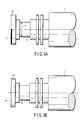
- FIG. 5 is a view for describing a second embodiment of the present invention.
- the repair method 10 for the rotor 1 by the high-velocity spray apparatus 6 in the third step S3 is implemented at one of the location of a generation plant on the site (a turbine generator including a rotor to be repaired) and the location of a repair factory, or at the location where these are disposed together.
- FIG. 5A is a front view
- FIG. 5B is a left side view of FIG. 5A
- FIG. 5C is a right side view of FIG. 5A.
- the structure shown comprises a rotor 1 to be repaired at the site; a rotor driving unit 14; a high-velocity flame spray apparatus 6 including a spray gun 6b for forming a spray coating 8; a horizontal spray gun driving unit 15 for moving the spray gun 6b in a direction horizontal to the rotational axis of the rotor 1; and a vertical spray gun driving unit 16 for moving the spray gun 6b in a direction perpendicular to the rotational axis of the rotor 1.
- the high-velocity flame spray apparatus 6 may not be provided with the vertical spray gun driving unit 16 of the horizontal spray gun driving unit 15 and vertical spray gun driving unit 16.
- the repair method 10 for the rotor 1 is normally implemented at an assembly factory. However, if repair is performed at the on-site generation plant where the to-be-repaired apparatus is installed, the time period for repair and the cost for repair can be reduced.
- the to-be-repaired object In usual cases, when repair is performed at the assembly factory, the to-be-repaired object is packaged and transported from the generation plant. A serious problem arises when the to-be-repaired object is transported, in particular, from a foreign country, although a similar problem arises with domestic transportation.
- a time period of, e.g. more than two months at maximum is required from the packing, transportation and customs clearance to the beginning of repair.
- the operation rate decreases due to the halt of the operation of the plant.
- the repair that can be performed at the on-site plant it is effective to perform the repair at the on-site generation plant. Only the indispensable, necessary repair items are conducted in the repair factory or assembly factory. Thereby, in the case of the on-site repair, the repair can be completed within two weeks at most.
- the thermal spray equipment which is installed as factory equipment, can be used.
- the thermal spray equipment installed at the factor includes a sound-proof chamber, a spraying robot, a control unit, a dust collecting unit, a cooling water chiller, a crane, and a rotor driving unit.
- FIG. 5 shows repair equipment which is substituted for the factory-installed spraying robot when the spray coating 8 is formed for repair.
- the spray gun 6b is fixed to the spray gun driving units 15 and 16 which can arbitrarily move the spray gun 6b in the horizontal direction 15a and vertical direction 16a relative to the rotational axis of the rotor 1.
- the robot is used if it can be transported to the on-site generation plant as the equipment capable of arbitrarily moving the spray gun in the horizontal direction 15a and vertical direction 16a. If the robot cannot be transported, the spray gun driving units 15 and 16, which use the driving mechanisms including ball screws and stepping motors, are employed.
- the equipment used is configured to include a spray gun movement table 17 which moves the spray gun 6b in the horizontal direction 15a and vertical direction 16a relative to the rotational axis of the rotor 1, and configured to be able to control the spray gun movement speed with a pitch of 0.1 mm/sec.
- the spray gun 6b is moved in the horizontal direction 15a to perform repair by thermal spray.
- the repair is performed by fixing the spray gun 6b to the spray gun driving units 15 and 16 which can arbitrarily move the spray gun 6b in the horizontal direction 15a and vertical direction 16a relative to the rotational axis.
- the spray gun 6a can be moved to an arbitrary position, and an optimal range for repair can arbitrarily be set.
- the spray gun 6b in the case of moving the spray gun in the vertical direction 16a, it is necessary to set the spray gun 6b at the center of the rotor diameter 1f.
- the adjustment can be performed in units of mm, and thermal spray repair with high -precision can advantageously be performed.
- the spray gun 6b is moved in the horizontal direction 15a while the rotor 1 is being rotated (arrow 14a). This aims at uniformly forming the spray coating 8 on the outer peripheral surface of the rotor 1.
- the spray gun 6b is fixed to the robot arm, and the arm of the robot is moved to perform spraying.
- the rotor 1 is rotated in the direction of arrow 14a by the device capable of rotating the rotor 1 in the direction of arrow 14a, for example, a rotating device having a rotating mechanism such as a lathe.
- the spray coating to be formed can uniformly formed on the outer periphery of the rotor 1, and the reliability of repair can be enhanced.
- the spray gun driving units 15 and 16 using the driving mechanisms including the ball screws and stepping motors are used. Thereby, the spray gun movement speed can be controlled with a pitch of 0.1 mm/sec, and the spray gun 6b can continuously and stably be moved while wobbling or vibration of the spray gun 6b during movement can be prevented.
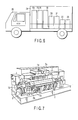
- FIG. 6 shows a third embodiment of the invention which relates to repair at the one-site generation plant.
- a thermal spray repair system 24, which comprises a spray gun 6b, spray gun driving units 15 and 16, a simplified sound-proof chamber 19, a cooling water chamber 20, a dust collecting unit 21, a generator 22 and a blasting unit 23, is mounted on a movable vehicle 25, so that repair 10 may be performed on the site with ease.
- thermal spray repair system 24 By simply transporting the thermal spray repair system 24 mounted on the vehicle 10, it becomes unnecessary to consume a great deal of labor in arranging for traffic means or transporting means both at domestic areas with inconvenient transportation means and at foreign countries. Repair work for the on-site generation plant can be conducted within a short time period.
- the present invention is usable in repairing a rotor of a hydraulic turbine, a gas turbine, a steam turbine, etc., or a rotor of a generator, etc.
Landscapes
- Engineering & Computer Science (AREA)
- Chemical & Material Sciences (AREA)
- Mechanical Engineering (AREA)
- Physics & Mathematics (AREA)
- Plasma & Fusion (AREA)
- Chemical Kinetics & Catalysis (AREA)
- Materials Engineering (AREA)
- Metallurgy (AREA)
- Organic Chemistry (AREA)
- Coating By Spraying Or Casting (AREA)
Priority Applications (1)
| Application Number | Priority Date | Filing Date | Title |
|---|---|---|---|
| EP10174475A EP2256226A1 (fr) | 2004-08-23 | 2004-08-23 | Procédé et dispositif pour répararer un rotor |
Applications Claiming Priority (1)
| Application Number | Priority Date | Filing Date | Title |
|---|---|---|---|
| PCT/JP2004/012061 WO2006021983A1 (fr) | 2004-08-23 | 2004-08-23 | Procédé et équipement de réparation d’un rotor |
Publications (2)
| Publication Number | Publication Date |
|---|---|
| EP1798302A1 true EP1798302A1 (fr) | 2007-06-20 |
| EP1798302A4 EP1798302A4 (fr) | 2009-12-02 |
Family
ID=35967206
Family Applications (1)
| Application Number | Title | Priority Date | Filing Date |
|---|---|---|---|
| EP04772022A Withdrawn EP1798302A4 (fr) | 2004-08-23 | 2004-08-23 | Procédé et équipement de réparation d'un rotor |
Country Status (2)
| Country | Link |
|---|---|
| EP (1) | EP1798302A4 (fr) |
| WO (1) | WO2006021983A1 (fr) |
Cited By (6)
| Publication number | Priority date | Publication date | Assignee | Title |
|---|---|---|---|---|
| EP1898048A1 (fr) * | 2005-06-17 | 2008-03-12 | Hitachi, Ltd. | Rotor pour turbine à vapeur et son procédé de fabrication |
| EP2166125A1 (fr) * | 2008-09-19 | 2010-03-24 | ALSTOM Technology Ltd | Procédé pour la configuration des services d'un réseau personnel |
| CN101736279B (zh) * | 2008-11-05 | 2012-07-18 | 沈阳黎明航空发动机(集团)有限责任公司 | 一种超音速火焰喷涂自润滑耐磨涂层工艺 |
| CN104191152A (zh) * | 2014-08-06 | 2014-12-10 | 陕西天元智能再制造有限公司 | 一种液压缸活塞杆或中级缸外表面的修复再制造方法 |
| CN104233162B (zh) * | 2014-08-06 | 2017-01-25 | 陕西天元智能再制造股份有限公司 | 一种活塞杆的表面修复方法 |
| EP3141629A1 (fr) * | 2015-09-10 | 2017-03-15 | General Electric Company | Procedes de traitement d'article |
Families Citing this family (1)
| Publication number | Priority date | Publication date | Assignee | Title |
|---|---|---|---|---|
| CN114682999B (zh) * | 2022-03-21 | 2023-07-28 | 中建隧道装备制造有限公司 | 一种盾构机中心回转体再制造工艺 |
Citations (6)
| Publication number | Priority date | Publication date | Assignee | Title |
|---|---|---|---|---|
| US5151308A (en) * | 1987-12-28 | 1992-09-29 | Amoco Corporation | High density thermal spray coating |
| WO1996005331A1 (fr) * | 1994-08-09 | 1996-02-22 | Telatek Oy | Procede de remise en etat de surfaces de pieces en acier |
| EP0927773A2 (fr) * | 1997-12-19 | 1999-07-07 | United Technologies Corporation | Outillage pour le positionnement des aubes d' une machine rotative |
| WO1999042632A1 (fr) * | 1998-02-19 | 1999-08-26 | Monitor Coatings And Engineers Limited | Traitement de surface des rotors |
| WO2000017490A2 (fr) * | 1998-09-03 | 2000-03-30 | Arnold James E | Procedes de reparation et de remise aux normes d'ailettes de turbine a gaz |
| EP1238742A1 (fr) * | 2001-02-22 | 2002-09-11 | Hickham Industries, Inc., (Texas Corporation) | Procédé d'application de matériaux de brasage sur un substrat nécessitant réparation |
Family Cites Families (6)
| Publication number | Priority date | Publication date | Assignee | Title |
|---|---|---|---|---|
| JPS5445638A (en) * | 1977-09-16 | 1979-04-11 | Shinichirou Nakaguchi | Regeneration of grooved roll by using molten metal projection |
| JPH11240624A (ja) * | 1997-12-10 | 1999-09-07 | Nippon Yuteku Kk | ロータリーバルブおよびその再生補修方法 |
| JP3564376B2 (ja) * | 2000-09-28 | 2004-09-08 | 三菱重工業株式会社 | 研磨層、燃焼エンジン、ガスタービン、及び、その製造方法 |
| JP3696521B2 (ja) * | 2001-04-12 | 2005-09-21 | 東栄技工株式会社 | 内燃機関のシリンダヘッド補修方法 |
| JP3905724B2 (ja) * | 2001-06-13 | 2007-04-18 | 三菱重工業株式会社 | Ni基合金製部品の補修方法 |
| JP3891888B2 (ja) * | 2002-06-19 | 2007-03-14 | 関西電力株式会社 | 円形鋼構造物の内壁面の自動溶射方法 |
-
2004
- 2004-08-23 WO PCT/JP2004/012061 patent/WO2006021983A1/fr active Application Filing
- 2004-08-23 EP EP04772022A patent/EP1798302A4/fr not_active Withdrawn
Patent Citations (6)
| Publication number | Priority date | Publication date | Assignee | Title |
|---|---|---|---|---|
| US5151308A (en) * | 1987-12-28 | 1992-09-29 | Amoco Corporation | High density thermal spray coating |
| WO1996005331A1 (fr) * | 1994-08-09 | 1996-02-22 | Telatek Oy | Procede de remise en etat de surfaces de pieces en acier |
| EP0927773A2 (fr) * | 1997-12-19 | 1999-07-07 | United Technologies Corporation | Outillage pour le positionnement des aubes d' une machine rotative |
| WO1999042632A1 (fr) * | 1998-02-19 | 1999-08-26 | Monitor Coatings And Engineers Limited | Traitement de surface des rotors |
| WO2000017490A2 (fr) * | 1998-09-03 | 2000-03-30 | Arnold James E | Procedes de reparation et de remise aux normes d'ailettes de turbine a gaz |
| EP1238742A1 (fr) * | 2001-02-22 | 2002-09-11 | Hickham Industries, Inc., (Texas Corporation) | Procédé d'application de matériaux de brasage sur un substrat nécessitant réparation |
Non-Patent Citations (1)
| Title |
|---|
| See also references of WO2006021983A1 * |
Cited By (9)
| Publication number | Priority date | Publication date | Assignee | Title |
|---|---|---|---|---|
| EP1898048A1 (fr) * | 2005-06-17 | 2008-03-12 | Hitachi, Ltd. | Rotor pour turbine à vapeur et son procédé de fabrication |
| EP1898048A4 (fr) * | 2005-06-17 | 2009-12-02 | Hitachi Ltd | Rotor pour turbine à vapeur et son procédé de fabrication |
| US8485788B2 (en) | 2005-06-17 | 2013-07-16 | Hitachi, Ltd. | Rotor for steam turbine and method of manufacturing the same |
| EP2166125A1 (fr) * | 2008-09-19 | 2010-03-24 | ALSTOM Technology Ltd | Procédé pour la configuration des services d'un réseau personnel |
| WO2010031696A1 (fr) * | 2008-09-19 | 2010-03-25 | Alstom Technology Ltd | Procédé pour la restauration d'un revêtement métallique |
| CN101736279B (zh) * | 2008-11-05 | 2012-07-18 | 沈阳黎明航空发动机(集团)有限责任公司 | 一种超音速火焰喷涂自润滑耐磨涂层工艺 |
| CN104191152A (zh) * | 2014-08-06 | 2014-12-10 | 陕西天元智能再制造有限公司 | 一种液压缸活塞杆或中级缸外表面的修复再制造方法 |
| CN104233162B (zh) * | 2014-08-06 | 2017-01-25 | 陕西天元智能再制造股份有限公司 | 一种活塞杆的表面修复方法 |
| EP3141629A1 (fr) * | 2015-09-10 | 2017-03-15 | General Electric Company | Procedes de traitement d'article |
Also Published As
| Publication number | Publication date |
|---|---|
| WO2006021983A1 (fr) | 2006-03-02 |
| EP1798302A4 (fr) | 2009-12-02 |
Similar Documents
| Publication | Publication Date | Title |
|---|---|---|
| US20070269608A1 (en) | Rotor repair method and rotor repair apparatus | |
| Yin et al. | Cold spray additive manufacturing and repair: Fundamentals and applications | |
| Tan et al. | Component repair using HVOF thermal spraying | |
| US7367488B2 (en) | Method of repair of thin wall housings | |
| US8240042B2 (en) | Methods of maintaining turbine discs to avert critical bucket attachment dovetail cracks | |
| CN1900488B (zh) | 固定叶片、包含这种叶片的涡轮机以及修理这种叶片的方法 | |
| JP4584999B2 (ja) | 蒸気タービン用ロータとその製造方法 | |
| KR20090007306A (ko) | 항공기 용도를 위한 알루미늄 합금을 포함하는 동적으로 응력이 가해진 구성요소의 수리 및 복원을 위한 방법 | |
| CA2867192A1 (fr) | Element comportant un revetement fixe par une liaison metallurgique | |
| EP1798302A1 (fr) | Procédé et équipement de réparation d"un rotor | |
| WO2003059569A9 (fr) | Procede de fabrication d'emplanture d'aube de turbine | |
| EP3486028A1 (fr) | Réparation de composants à l'aide de la fabrication additive avec travail à froid in situ | |
| WO2017083273A1 (fr) | Revêtement thermique pour joints mécaniques | |
| EP2256226A1 (fr) | Procédé et dispositif pour répararer un rotor | |
| WO1996005331A1 (fr) | Procede de remise en etat de surfaces de pieces en acier | |
| JPH11240624A (ja) | ロータリーバルブおよびその再生補修方法 | |
| EP2189239B1 (fr) | Procédé de fabrication de composant usiné pour améliorer la durée de vie de fatigue oligocyclique | |
| Vardavoulias et al. | Industrial component restoration using thermal spray technologies | |
| EP3199659B1 (fr) | Procédé de fabrication d'un composant cylindrique à haute température pour turbine à gaz | |
| US20100284793A1 (en) | Method of electrical discharge surface repair of a variable vane trunnion | |
| CN114134447B (zh) | 一种迷宫密封式盖板内孔巴氏合金层的修复方法 | |
| Yin et al. | Industrial applications of cold spray additive manufacturing | |
| CN116100029A (zh) | 用于航空发动机篦齿盘损伤的修复方法 | |
| CN113755781A (zh) | 一种飞机高压涡轮间隙阀圆柱轴密封面修理方法 | |
| Belyakov et al. | Electric Spark Coating Formation during Repair and Manufacture of Power Equipment Elements |
Legal Events
| Date | Code | Title | Description |
|---|---|---|---|
| PUAI | Public reference made under article 153(3) epc to a published international application that has entered the european phase |
Free format text: ORIGINAL CODE: 0009012 |
|
| 17P | Request for examination filed |
Effective date: 20070222 |
|
| AK | Designated contracting states |
Kind code of ref document: A1 Designated state(s): DE FR GB |
|
| DAX | Request for extension of the european patent (deleted) | ||
| RBV | Designated contracting states (corrected) |
Designated state(s): DE FR GB |
|
| A4 | Supplementary search report drawn up and despatched |
Effective date: 20091029 |
|
| 17Q | First examination report despatched |
Effective date: 20100429 |
|
| RAP1 | Party data changed (applicant data changed or rights of an application transferred) |
Owner name: KABUSHIKI KAISHA TOSHIBA |
|
| STAA | Information on the status of an ep patent application or granted ep patent |
Free format text: STATUS: THE APPLICATION IS DEEMED TO BE WITHDRAWN |
|
| 18D | Application deemed to be withdrawn |
Effective date: 20110128 |