EP1798065B1 - Tread pattern of a tire comprising sipes - Google Patents
Tread pattern of a tire comprising sipes Download PDFInfo
- Publication number
- EP1798065B1 EP1798065B1 EP06123499A EP06123499A EP1798065B1 EP 1798065 B1 EP1798065 B1 EP 1798065B1 EP 06123499 A EP06123499 A EP 06123499A EP 06123499 A EP06123499 A EP 06123499A EP 1798065 B1 EP1798065 B1 EP 1798065B1
- Authority
- EP
- European Patent Office
- Prior art keywords
- profile block
- profile
- extension
- block row
- groove
- Prior art date
- Legal status (The legal status is an assumption and is not a legal conclusion. Google has not performed a legal analysis and makes no representation as to the accuracy of the status listed.)
- Not-in-force
Links
Images


Classifications
-
- B—PERFORMING OPERATIONS; TRANSPORTING
- B60—VEHICLES IN GENERAL
- B60C—VEHICLE TYRES; TYRE INFLATION; TYRE CHANGING; CONNECTING VALVES TO INFLATABLE ELASTIC BODIES IN GENERAL; DEVICES OR ARRANGEMENTS RELATED TO TYRES
- B60C11/00—Tyre tread bands; Tread patterns; Anti-skid inserts
- B60C11/03—Tread patterns
- B60C11/0302—Tread patterns directional pattern, i.e. with main rolling direction
-
- B—PERFORMING OPERATIONS; TRANSPORTING
- B60—VEHICLES IN GENERAL
- B60C—VEHICLE TYRES; TYRE INFLATION; TYRE CHANGING; CONNECTING VALVES TO INFLATABLE ELASTIC BODIES IN GENERAL; DEVICES OR ARRANGEMENTS RELATED TO TYRES
- B60C11/00—Tyre tread bands; Tread patterns; Anti-skid inserts
- B60C11/03—Tread patterns
- B60C11/12—Tread patterns characterised by the use of narrow slits or incisions, e.g. sipes
- B60C11/1204—Tread patterns characterised by the use of narrow slits or incisions, e.g. sipes with special shape of the sipe
- B60C2011/1213—Tread patterns characterised by the use of narrow slits or incisions, e.g. sipes with special shape of the sipe sinusoidal or zigzag at the tread surface
-
- B—PERFORMING OPERATIONS; TRANSPORTING
- B60—VEHICLES IN GENERAL
- B60C—VEHICLE TYRES; TYRE INFLATION; TYRE CHANGING; CONNECTING VALVES TO INFLATABLE ELASTIC BODIES IN GENERAL; DEVICES OR ARRANGEMENTS RELATED TO TYRES
- B60C11/00—Tyre tread bands; Tread patterns; Anti-skid inserts
- B60C11/03—Tread patterns
- B60C11/12—Tread patterns characterised by the use of narrow slits or incisions, e.g. sipes
- B60C11/1236—Tread patterns characterised by the use of narrow slits or incisions, e.g. sipes with special arrangements in the tread pattern
- B60C2011/1245—Tread patterns characterised by the use of narrow slits or incisions, e.g. sipes with special arrangements in the tread pattern being arranged in crossing relation, e.g. sipe mesh
-
- B—PERFORMING OPERATIONS; TRANSPORTING
- B60—VEHICLES IN GENERAL
- B60C—VEHICLE TYRES; TYRE INFLATION; TYRE CHANGING; CONNECTING VALVES TO INFLATABLE ELASTIC BODIES IN GENERAL; DEVICES OR ARRANGEMENTS RELATED TO TYRES
- B60C11/00—Tyre tread bands; Tread patterns; Anti-skid inserts
- B60C11/03—Tread patterns
- B60C11/12—Tread patterns characterised by the use of narrow slits or incisions, e.g. sipes
- B60C11/1272—Width of the sipe
- B60C2011/1277—Width of the sipe being narrow, i.e. less than 0.3 mm
Landscapes
- Engineering & Computer Science (AREA)
- Mechanical Engineering (AREA)
- Tires In General (AREA)
Abstract
Description
Die Erfindung betrifft ein Laufstreifenprofil eines Fahrzeugluftreifens - insbesondere eines Winterreifens - mit wenigstens einer über den Umfang des Fahrzeugluftreifens erstreckten Profilblockreihe mit in Umfangsrichtung U hintereinander angeordneten, jeweils durch Querrillen voneinander getrennten Profilblockelementen mit einem in der radial äußeren Oberfläche von Profilblockelementen der Profilblockreihe ausgebildeten gitterförmigen Feineinschnittsystem.The invention relates to a tread pattern of a pneumatic vehicle tire - especially a winter tire - arranged with at least one over the circumference of the vehicle pneumatic tire profile block row arranged in the circumferential direction U, each separated by transverse grooves profile block elements with a formed in the radially outer surface of profile block elements of the profile block row latticed fine sipe system.
Es sind Laufstreifenprofile von Winterreifen bekannt mit über den Umfang des Fahrzeugluftreifens erstreckten Profilblockreihe mit in Umfangsrichtung U hintereinander angeordneten, jeweils durch Querrillen voneinander getrennten Profilblockelementen mit in der radial äußeren Oberfläche von Profilblockelementen der Profilblockreihe ausgebildeten parallelen geradlinigen oder sinusförmig gewellten Feineinschnitten. Diese Ausbildung ermöglichen durch eine sehr begrenzte Zahl von parallelen Feineinschnitte Griffkanten für guten Schneegriff und Flexibilität des Profilblockes hauptsächlich in eine Richtung.There are tread patterns of winter tires known with over the circumference of the vehicle pneumatic tire extended profile block row arranged in the circumferential direction U behind the other, each separated by transverse grooves profile block elements formed in the radially outer surface of the profile block elements of the profile block row parallel rectilinear or sinusoidal corrugated fine incisions. This training allow by a very limited number of parallel sipes grip edges for good snow grip and flexibility of the profile block mainly in one direction.
Darüber hinaus sind Laufstreifenprofile von Winterreifen bekannt mit über den Umfang des Fahrzeugluftreifens erstreckten Profilblockreihe mit in Umfangsrichtung U hintereinander angeordneten, jeweils durch Querrillen voneinander getrennten Profilblockelementen bekannt, bei denen in der radial äußeren Oberfläche der Profilblockelementen der Profilblockreihe gitterförmigen Feineinschnittsysteme, die sich jeweils über das gesamte Profilblockelement erstrecken, bekannt. Die Feineinschnittgitter ermöglichen eine hohe Griffkantenzahl und eine hohe Flexibilität der vom Feineinschnittgitter umrahmten Profilblockausschnittselemente für einen guten Schneegriff in Längs- und in Querrichtung. Die durch diese Feineinschnittsgitter einhergehende hohe Flexibilität des gesamten Profilblockelements kann jedoch zu hoher Klotzverformung führen, wodurch alle Trockeneigenschaften wie z.B. Traktions-, Handling- und auch Aquaplaningeigenschaften negativ beeinflusst werden können.In addition, tread strips of winter tires are known with over the circumference of the vehicle pneumatic tire extended profile block row arranged in the circumferential direction U behind each other, each separated by transverse grooves profile block elements, in which in the radially outer surface of the profile block elements of the profile block row lattice-shaped fine incision systems, each extending over the entire Protruding profile block element, known. The fine incision grids enable a high grip edge number and a high degree of flexibility of the profile block cut-out elements framed by the fine incision grille for a good snow grip in the longitudinal and in the transverse direction. However, the high flexibility of the entire tread block element, which is accompanied by these fine incision grids, can lead to high block deformation, as a result of which all drying properties such as, for example, traction, handling and also aquaplaning properties can be negatively influenced.
Aus der
Der Erfindung liegt daher die Aufgabe zugrunde, ein Laufstreifenprofil eines Fahrzeugluftreifens - insbesondere eines Winterreifens - mit wenigstens einer über den Umfang des Fahrzeugluftreifens erstreckten Profilblockreihe mit in Umfangsrichtung U hintereinander angeordneten, jeweils durch Querrillen voneinander getrennten Profilblockelementen zu ermögliche, bei dem die großen Vorteile eines gitterförmigen Feineinschnittsystems mit Verbesserung der Trockeneigenschaften des Fahrzeugreifens verbunden werden können.The invention is therefore based on the object, a tread pattern of a pneumatic vehicle tire - especially a winter tire - with at least one over the circumference of the vehicle pneumatic tire extended profile block row arranged in the circumferential direction U behind each other, each made possible by transverse grooves separate block block elements, in which the great advantages of a grid-shaped Fine incision system can be associated with improving the dry properties of the vehicle tire.
Erfindungsgemäß gelöst wird die Aufgabe durch die Ausbildung eines Laufstreifenprofil eines Fahrzeugluftreifens - insbesondere eines Winterreifens - mit wenigstens einer über den Umfang des Fahrzeugluftreifens erstreckten Profilblockreihe mit in Umfangsrichtung U hintereinander angeordneten, jeweils durch Querrillen voneinander getrennten Profilblockelementen gemäß den Merkmalen von Anspruch 1 mit einem in der radial äußeren Oberfläche von Profilblockelementen der Profilblockreihe ausgebildeten gitterförmigen Feineinschnittsystem, mit zwei in der radial äußeren Oberfläche des Profilblockelements ausgebildeten Zonen, die sich axial längs der Erstreckung des gitterförmigen Feineinschnittsystems über die gesamte axiale Erstreckung des gitterförmigen Feineinschnittsystems im Profilblockelement und in Umfangsrichtung zwischen jeweils einer der beiden das Profilblockelement in Umfangsrichtung zu einer Querrille hin begrenzenden Profilblockelementflanke und dem gitterförmigen Feineinschnittsystem über einen in Umfangsrichtung gemessenen Abstand w mit w > 0 mm hin erstrecken, der frei von Feineinschnitten ausgebildet ist, wobei in Umfangsrichtung (U) des Fahrzeugluftreifens gesehen jeweils zwei hintereinander angeordnete Profilblockelemente einer ersten Profilblockreihe in ihrer Umfangserstreckung einem Profilblockelement einer zweiten Profilblockreihe zugeordnet sind, wobei in der ersten Profilblockreihe in Umfangsrichtung (U) jeweils in alternierender Reihenfolge eine erste Querrille und eine zweite Querrille der ersten Profilblockreihe ausgebildet ist, wobei die erste Querrille in ihrer axialen Verlängerung in eine in der zweiten Profilblockreihe ausgebildeten Querrille übergeht, wobei die erste Querrille mit einer senkrecht zu ihrer Erstreckungsrichtung gemessenen Breite - insbesondere konstanten Breite - d und die zweite Querrille mit einer senkrecht zu ihrer Erstreckungsrichtung gemessenen Breite - insbesondere konstanten Breite - e ausgebildet ist, wobei für d und e in der radial äußeren Oberfläche des Fahrzeugluftreifens gilt: (0,3 d) ≤ e ≤ (0,95 d).The object is achieved by the formation of a tread pattern of a pneumatic vehicle tire - especially a winter tire - with at least one over the circumference of the pneumatic vehicle tire tread row arranged in the circumferential direction U behind each other, each separated by transverse grooves profile block elements according to the features of
Durch die feineinschnittfreien Randzonen sind die Profilblockelemente im für die Trockeneigenschaften wichtigen Randbereich versteift, wobei Feineinschnittgitter im innern der Profilblockelements die hohe Dichte und Zahl von Griffkanten und Flexibilität der durch das Feineinschnittgitter umrahmten Profilblockausschnittelemente zum sicheren Griff auf Schnee und schneeähnlichem Untergrund sowohl in axialer als auch in Umfangsrichtung des Fahrzeugluftreifens ermöglicht. Durch die Ausbildung, bei der in Umfangsrichtung (U) des Fahrzeugluftreifens gesehen jeweils zwei hintereinander angeordnete Profilblockelemente einer ersten Profilblockreihe in ihrer Umfangserstreckung einem Profilblockelement einer zweiten Profilblockreihe zugeordnet sind, wobei in der ersten Profilblockreihe in Umfangsrichtung (U) jeweils in alternierender Reihenfolge eine erste Querrille und eine zweite Querrille der ersten Profilblockreihe ausgebildet ist, wobei die erste Querrille in ihrer axialen Verlängerung in eine in der zweiten Profilblockreihe ausgebildeten Querrille übergeht, wobei die erste Querrille mit einer senkrecht zu ihrer Erstreckungsrichtung gemessenen Breite - insbesondere konstanten Breite - d und die zweite Querrille mit einer senkrecht zu ihrer Erstreckungsrichtung gemessenen Breite - insbesondere konstanten Breite - e ausgebildet ist, wobei für d und e in der radial äußeren Oberfläche des Fahrzeugluftreifens gilt: (0,3 d) ≤ e ≤ (0,95 d), wird eine hohe Umfangssteifigkeit bei hoher Wasserableitbarkeit aus dem Profil und somit gute Handlingeigenschaften und Aquaplaningeigenschaften ermöglicht. Die Ausbildung ermöglicht somit gute Trockeneigenschaften wie z.B.. Traktions- und Handlingeigenschaften und gute Aquaplaningeigenschaften.Thanks to the fine-cut-free edge zones, the profile block elements are stiffened in the edge area important for the drying properties, with fine-cut lattices in the interior of the profile block element, the high density and number of grip edges and flexibility the framed by the fine incision grating profile block cutting elements for safe grip on snow and snow-like ground both in the axial and in the circumferential direction of the pneumatic vehicle tire allows. As a result of the design, in the peripheral direction (U) of the pneumatic vehicle tire two successively arranged profile block elements of a first profile block row are assigned in their peripheral extension to a profile block element of a second profile block row, wherein in the first profile block row in the circumferential direction (U) in each case a first transverse groove and a second transverse groove of the first profile block row is formed, wherein the first transverse groove merges in its axial extension into a transverse groove formed in the second profile block row, the first transverse groove having a width measured perpendicular to its direction of extension - in particular constant width - d and the second transverse groove is formed with a width measured perpendicularly to its extension direction-in particular constant width-e, where for d and e in the radially outer surface of the pneumatic vehicle tire: (0.3 d) ≦ e ≦ (0.95 d), an h High circumferential stiffness with high water drainability from the profile and thus good handling properties and aquaplaning properties possible. The training thus allows good dry properties such as. Traction and handling properties and good aquaplaning properties.
Besonders vorteilhaft ist eine Ausbildung eines Laufstreifenprofils gemäß den Merkmalen von Anspruch 2, wobei sich das gitterförmige Feineinschnittsystem eines Profilblockelements jeweils über die gesamte axiale Erstreckung des Profilblockelements im Umfangserstreckungsbereich des gitterförmigen Feineinschnittsystems innerhalb der axialen Erstreckungsbreite TA der Bodenaufstandsfläche des Fahrzeugluftreifens im montierten, belasteten Betriebszustand unter Normbedingungen (gemäß E.T.R.T.O. Standards) erstreckt. Hierdurch können Schnee- und Eisgriff verbessert werden.Particularly advantageous is a design of a tread pattern according to the features of
Besonders vorteilhaft ist eine Ausbildung eines Laufstreifenprofils gemäß den Merkmalen von Anspruch 3, wobei ein oder mehrere der Profilblockelemente einer Profilblockrehe in ihrer radial äußeren Oberfläche mit mehreren - insbesondere mit zwei - in Umfangsrichtung hintereinander angeordnet und von einander beabstandeten gitterförmigen Feineinschnittsystemen ausgebildet sind, mit jeweils einer in Umfangsrichtung zwischen den hintereinander angeordneten gitterförmigen Feineinschnittsystemen ausgebildeten Zone, die sich axial längs der Erstreckung des gitterförmigen Feineinschnittsysteme über die gesamte axiale Erstreckung der gitterförmigen Feineinschnittsysteme im Profilblockelement über einen in Umfangsrichtung gemessenen Abstand w mit w > 0 mm hin erstrecken, der frei von Feineinschnitten ausgebildet ist. Hierdurch kann der Zielkonflikt aus guten Handlingeigenschaften, Trockenbremsen und guten Wintereigenschaften besser gelöst werden.Particularly advantageous is an embodiment of a tread pattern according to the features of
Besonders vorteilhaft ist eine Ausbildung eines Laufstreifenprofils gemäß den Merkmalen von Anspruch 4, mit mehreren zwischen einer Reifenschulter und der Äquatorebene des Fahrzeugluftreifens jeweils über den Umfang des Fahrzeugluftreifens erstreckten Profilblockreihen mit in Umfangsrichtung U hintereinander angeordneten, jeweils durch Querrillen voneinander getrennten Profilblockelementen, bei denen jeweils in der radial äußeren Oberfläche von Profilblockelementen jeder dieser Profilblockreihen ausgebildetem gitterförmigen Feineinschnittsystemen und derartige von Feineinschnitten freien Zonen ausgebildet sind, wobei innerhalb der axialen Erstreckungsbreite TA der Bodenaufstandsfläche des Fahrzeugluftreifens im montierten, belasteten Betriebszustand unter Normbedingungen (gemäß E.T.R.T.O. Standards) die Fläche der von Feineinschnitten jeweils freien Zonen in der axial der Reifenschulter nächstgelegenen Profilblockreihe größer als die Fläche der von Feineinschnitten freien Zonen in der axial von der Reifenschulter axial am weitest entfernt gelegenen Profilblockreihe ausgebildet ist. Hierdurch können die Handlingeigenschaften und die Aquaplaningeigenschaften positiv beeinflusst werden.Particularly advantageous is a design of a tread pattern according to the features of
Besonders vorteilhaft ist eine Ausbildung eines Laufstreifenprofils gemäß den Merkmalen von Anspruch 5, mit mehreren zwischen einer Reifenschulter und der Äquatorebene des Fahrzeugluftreifens jeweils über den Umfang des Fahrzeugluftreifens erstreckten Profilblockreihen mit in Umfangsrichtung U hintereinander angeordneten, jeweils durch Querrillen voneinander getrennten Profilblockelementen, bei denen jeweils in der radial äußeren Oberfläche von Profilblockelementen jeder dieser Profilblockreihen ausgebildetem gitterförmigen Feineinschnittsystemen und derartige von Feineinschnitten freien Zonen ausgebildet sind, wobei innerhalb der axialen Erstreckungsbreite TA der Bodenaufstandsfläche des Fahrzeugluftreifens im montierten, belasteten Betriebszustand unter Normbedingungen (gemäß E.T.R.T.O. Standards) die Fläche der von Feineinschnitten jeweils freien Zonen in einer axial der Reifenschulter näher gelegenen ersten Profilblockreihe jeweils größer als die Fläche der von Feineinschnitten freien Zonen in der axial weiter innen liegenden zur ersten Profilblockreihe benachbarten Profilblockreihe ausgebildet ist. Hierdurch können die Handlingeigenschaften und die Aquaplaningeigenschaften positiv beeinflusst werden.Particularly advantageous is a design of a tread pattern according to the features of claim 5, with a plurality of between a tire shoulder and the equatorial plane of the pneumatic vehicle tire respectively over the circumference of the vehicle pneumatic tire extended profile block rows arranged in the circumferential direction U behind each other, each separated by transverse grooves profile block elements, in each of which the radially outer surface of the profile block elements of each of these profile block rows trained lattice-shaped fine sipe systems and such sipe-free zones are formed, wherein within the axial extension width TA of the ground contact surface of the pneumatic vehicle tire in the mounted, loaded operating condition under standard conditions (according to ETRTO standards) the surface of the sipes each free Zones in an axially closer to the tire shoulder first block profile each larger than the surface of fine incisions is formed free zones in the axially further inwardly lying to the first profile block row profile block row. As a result, the handling properties and the aquaplaning properties can be positively influenced.
Besonders vorteilhaft ist eine Ausbildung eines Laufstreifenprofils gemäß den Merkmalen von Anspruch 6, wobei die erste Profilblockreihe eine Schulterprofilblockreihe ist, wobei die zweite Profilblockreihe eine axial zur Schulterprofilblockreihe unmittelbar benachbarte von der Schulterprofilblockreihe durch eine über den gesamten Umfang des Fahrzeugluftreifens erstreckt ausgebildete Umfangsrille axial beabstandete Profilblockreihe ist. Hierdurch können die Handlingeigenschaften und die Aquaplaningeigenschaften positiv beeinflusst werden.Particularly advantageous is a design of a tread pattern according to the features of claim 6, wherein the first profile block row is a shoulder profile block row, wherein the second profile block row axially adjacent to the shoulder profile block row of the shoulder profile block row through a over the entire circumference of Pneumatic vehicle tire extends trained circumferential groove axially spaced profile block row is. As a result, the handling properties and the aquaplaning properties can be positively influenced.
Besonders vorteilhaft ist eine Ausbildung eines Laufstreifenprofils gemäß den Merkmalen von Anspruch 7, wobei die feineinschnittsfreien Zonen der Profilblockelemente der ersten Profilblockreihe eine Fläche FC innerhalb der axialen Erstreckungsbreite TA der Bodenaufstandsfläche des Fahrzeugluftreifens im montierten, belasteten Betriebszustand unter Normbedingungen (gemäß E.T.R.T.O. Standards) und die feineinschnittsfreien Zonen der Profilblockelemente der zweiten Profilblockreihe eine Fläche FD aufweisen, wobei für FC und FD gilt: (0,9 FC ) < FD <(1,7 FC). Hierdurch kann eine optimal abgestimmte Steifigkeit für Aquaplaning, Trockenbremsen und Abrieb erzielt werden.Particularly advantageous is a design of a tread pattern according to the features of
Besonders vorteilhaft ist eine Ausbildung eines Laufstreifenprofils gemäß den Merkmalen von Anspruch 8, wobei innerhalb der axialen Erstreckungsbreite TA der Bodenaufstandsfläche des Fahrzeugluftreifens im montierten, belasteten Betriebszustand unter Normbedingungen (gemäß E.T.R.T.O. Standards) die axiale Erstreckungsbreite der axial zur außen zur Reifenschulter hin ausgebildeten Profilblockreihe größer als die axiale Erstreckungsbreite der axial weiter von der Reifenschulter entfernt angeordneten Profilblockreihe ist. Hierdurch können die Handlingeigenschaften positiv beeinflusst werden.Particularly advantageous is a design of a tread pattern according to the features of
Besonders vorteilhaft ist eine Ausbildung eines Laufstreifenprofils gemäß den Merkmalen von Anspruch 9, wobei benachbart zur zweiten Profilblockreihe in axial von der ersten Profilblockreihe wegweisenden Richtung eine über den Umfang des Fahrzeugluftreifens erstreckt ausgebildete Profilrippe (9) ausgebildet ist, die an ihrer radial äußeren Oberfläche insbesondere mit einem gitterförmigen Feineinschnittsystem ausgebildet ist. Hierdurch können die Handlingeigenschaften und die Trockenbremseigenschaften positiv beeinflusst werden.Particularly advantageous is a design of a tread pattern according to the features of claim 9, wherein adjacent to the second profile block row in the direction away from the first profile block row direction over the circumference of the vehicle pneumatic tire extending trained profile rib (9) is formed on its radially outer surface in particular with a lattice-shaped sipe system is formed. As a result, the handling properties and the dry braking properties can be positively influenced.
Besonders vorteilhaft ist eine Ausbildung eines Laufstreifenprofils gemäß den Merkmalen von Anspruch 10, wobei innerhalb der axialen Erstreckungsbreite TA der Bodenaufstandsfläche des Fahrzeugluftreifens im montierten, belasteten Betriebszustand unter Normbedingungen (gemäß E.T.R.T.O. Standards) für die axiale Erstreckungsbreite C der ersten Profilblockreihe, für die axiale Erstreckungsbreite D der zweiten Profilblockreihe und für die axiale Erstreckungsbreite B der Profilrippe (9) gilt:
D > C > B. Dies ermöglicht eine optimale Steifigkeitsverteilung in Querrichtung des Fahrzeugluftreifens im Zielkonflikt aus Handlingeigenschaften auf trockener Oberfläche gegenüber Laufleistung des Fahrzeugluftreifens. Durch Ausbildung mit B ≤ (0,18 TA) kann ermöglicht werden, dass die Mittenrippe im Aquaplaningfall wie ein Schiffsbug den Wasserfilm auch bei hohem Schlupf noch wirksam durchschneidet.Particularly advantageous is a design of a tread strip according to the features of claim 10, wherein within the axial extension width TA of the ground contact surface of the pneumatic vehicle tire in the mounted, loaded operating condition under standard conditions (according to ETRTO standards) for the axial extension width C of the first profile block row, for the axial extension width D of the second profile block row and for the axial extension width B of the profile rib (9):
D>C> B. This allows an optimal stiffness distribution in the transverse direction of the pneumatic vehicle tire in the conflict of objectives from handling properties on a dry surface compared to mileage of the pneumatic vehicle tire. By training with B ≤ (0.18 TA) it can be made possible that the center rib in the aquaplaning case, such as a ship's bow, effectively cuts through the water film even during high slip.
Besonders vorteilhaft ist eine Ausbildung eines Laufstreifenprofils gemäß den Merkmalen von Anspruch 11, wobei zwischen den Profilblockelementen der zweiten Profilblockreihe und der Profilrippe ein erster Rillenabschnitt (16') einer Rille ausgebildet ist, der die Profilrippe axial vom Profilblockelement trennt, der unter Einschluss eines Winkels (γ) zur Axialen des Fahrzeugluftreifens erstreckt verlaufend ausgebildet ist, und unter Ausbildung eines Knickes in axiale Richtung zu der eine Schulterprofilblockreihe bildenden ersten Profilblockreihe in einen zweiten Rillenabschnitt (16") der Rille übergeht, der das Profilblockelement von dem in Umfangsrichtung nach geordneten Profilblockelement der Profilblockreihe trennt, wobei der zweiten Rillenabschnitt (16") der Rille unter Einschluss eines Winkels (β) zur Axialen des Fahrzeugluftreifens erstreckt verlaufend ausgebildet ist. Hierdurch können die Handlingeigenschaften und die Aquaplaningeigenschaften positiv beeinflusst werden.Particularly advantageous is a design of a tread pattern according to the features of
Besonders vorteilhaft ist eine Ausbildung eines Laufstreifenprofils gemäß den Merkmalen von Anspruch 12, wobei die erste eine Schulterprofilblockreihe bildende Profilblockreihe (3) und die axial benachbarte zweite Profilblockreihe (8) durch eine in Umfangrichtung (U) des Fahrzeugluftreifens über den gesamten Umfang des Fahrzeugluftreifens erstreckt ausgebildete Umfangsrille (4) axial getrennt ist, wobei die Umfangsrille (4) mit einem in Umfangsrichtung zickzack-förmigem Verlauf ausgebildet ist. Hierdurch können die Schneegriffeigenschaften und die Aquaplaningeigenschaften positiv beeinflusst werden.Particularly advantageous is a design of a tread pattern according to the features of
Besonders vorteilhaft ist eine Ausbildung eines Laufstreifenprofils gemäß den Merkmalen von Anspruch 13, wobei der erste Rillenabschnitt (16') der Rille (16) in ihrer senkrecht zu ihrer Erstreckungsrichtung gemessenen Breite ausgehend von einer Breite a längs ihrer Erstreckung bis zu einer Breite b an der Knickstelle - insbesondere linear - zunimmt, wobei der zweite Rillenabschnitt (16") der Rille (16) in ihrer senkrecht zu ihrer Erstreckungsrichtung gemessenen Breite mit konstanter Breite b längs ihrer Erstreckung ausgebildet ist, wobei für die Breiten a, b und c gilt: a < b ≤ c, wobei insbesondere (1,2 a) ≤ b ≤ (2,3 a). Hierdurch kann die Drainage aus dem Profilinnern optimiert werden.Particularly advantageous is a design of a tread strip according to the features of
Besonders vorteilhaft ist eine Ausbildung eines Laufstreifenprofils gemäß den Merkmalen von Anspruch 14, wobei das Laufstreifenprofil laufrichtungsgebunden ausgebildet ist. Hierdurch können die Handlingeigenschaften, die Aquaplaningeigenschaften, Schnee- und Eisgriff positiv beeinflusst werden.Particularly advantageous is a design of a tread pattern according to the features of
Die Erfindung wird im Folgenden an Hand der in den
- Fig. 1
- Fahrzeugluftreifen mit Laufflächenprofil in perspektivischer Darstellung,
- Fig. 2
- Draufsicht auf einen Umfangsausschnitt des Laufstreifenprofils von
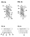
Fig. 1 , - Fig. 3a
- Vergrößertes Profilblockelement zur Erläuterung des erfindungsgemäß ausgebildeten Feineinschnittgitters im unbelasteten Zustand,
- Fig. 3b
- Profilblockelement von
Fig. 3 a in Schnittdarstellung X-X vonFig. 3a , - Fig. 4a
- Vergrößertes Profilblockelement von
Fig. 3a zur Erläuterung des Gleiteffektes im Feineinschnittgitter im belasteten Zustand beim Durchlaufen des Reifenlatsches - Fig. 4b
- Profilblockelement von
Fig. 4 a in Schnittdarstellung X-X vonFig. 4a .
- Fig. 1
- Pneumatic vehicle tire with tread pattern in perspective,
- Fig. 2
- Top view of a circumferential section of the tread pattern of
Fig. 1 . - Fig. 3a
- Enlarged profile block element for explaining the inventively embodied sipe grating in the unloaded state,
- Fig. 3b
- Profile block element of
Fig. 3 a in section XX ofFig. 3a . - Fig. 4a
- Enlarged profile block element of
Fig. 3a to explain the sliding effect in the fine incision grid in the loaded state when passing through the tire lash - Fig. 4b
- Profile block element of
Fig. 4 a in section XX ofFig. 4a ,
Der in
In
Bei dem in
Wie in
Die linke Schulterprofilblockreihe 3 erstreckt sich ebenso wie die rechte Schulterprofilblockreihe 7 über den gesamten Umfang des Fahrzeugluftreifens in Umfangsrichtung U und ist in jeweils aus einer Vielzahl von in Umfangsrichtung U hintereinander angeordneten Profilblockelementen 11 bzw. 14 ausgebildet. Dabei sind die in Umfangsrichtung U hintereinander angeordneten Profilblockelemente 11 der Schulterprofilblockreihe 3 in Umfangsrichtung U in alternierender Reihenfolge durch Querrillen 15 bzw. durch Querrillen 38 voneinander getrennt. Die in Umfangsrichtung U hintereinander angeordneten Profilblockelemente 14 der Schulterprofilblockreihe 7 in Umfangsrichtung U in alternierender Reihenfolge durch Querrillen 19 bzw. durch Querrillen 18 voneinander getrennt.The left shoulder
Das Mittenprofilband 5 ist aus einer zentralen über den Umfang des Fahrzeugluftreifens in Umfangsrichtung U ausgerichtet erstreckten Profilrippe 9 ausgebildet, deren axiale Flanken im wesentlichen aus über den Umfang des Fahrzeugluftreifens verteilten ersten Umfangsabschnitten ausgebildet sind, die in der entgegen der Abrollrichtung F eingetragenen Umfangsrichtung U gesehen unter Einschluss eines Neigungswinkels zur Axialen A von der Profilrippe 9 axial wegweisend nach außen zu der jeweiligen Reifenschulter hin geneigt verlaufen und zwischen denen jeweils in Umfangsrichtung gegenüber den ersten Umfangsabschnitten deutlich kürzere zweite Umfangsabschnitte ausgebildet sind, in denen die jeweilige Flanke einen axial gegenläufig steigend verlaufenden Versatzabschnitt in axialer Richtung zur Rippenmitte der Profilrippe 9 hin mit einem deutlich kleineren Neigungswinkel zur Axialen A aufweisen. Die Umfangspositionen des axialen Versatzes auf der rechts dargestellten Rippenflanke der Profilrippe 9 sind gegenüber den Umfangspositionen des axialen Versatzes auf der linken Rippenflanke der Profilrippe 9 in Umfangsrichtung des Fahrzeugluftreifens versetzt zu einander ausgebildet. Ausgehend von den den axialen Versatz darstellenden kurzen Umfangsabschnitten mit axial nach innen zur Profilrippenmitte hin steigend verlaufenden Abschnitts der jeweiligen Rippenflanke der Profilrippe 9 sind jeweils Profilblockelemente 12 bzw. Profilblockelemente 13 ausgebildet, die sich von der Position des kurzen Versatzes in die entgegen der Abrollrichtung F eingetragene Umfangsrichtung U gesehen und von der Profilrippe 9 weg weisend nach axial außen erstrecken, wobei sich die Profilblockelemente 12 von der Profilrippe 9 ausgehend in Richtung der Schulterprofilblockreihe 3 und die Profilblockelemente 13 in Richtung der Schulterprofilblockreihe 14 erstrecken. Die in Umfangsrichtung U des Fahrzeugluftreifens hintereinander angeordneten Profilblockelemente 12 bilden in Umfangsrichtung U des Fahrzeugluftreifens gesehen eine über den Versatz an die Profilrippe 9 angelehnte Profilblockreihe 8. Die Profilblockelemente 13 bilden in Umfangsrichtung U des Fahrzeugluftreifens gesehen eine über den Versatz an die Profilrippe 9 angelehnte Profilblockreihe 10.The center profile band 5 is formed from a central over the circumference of the vehicle pneumatic tire in the circumferential direction U aligned profiled rib 9, the axial edges are formed substantially over the circumference of the vehicle pneumatic tire distributed first circumferential portions, seen in the counter to the rolling direction F registered circumferential direction U below Inclusion of an inclination angle to the axial A of the tread rib 9 axially pointing away outwards to the respective tire shoulder inclined and between each in the circumferential direction relative to the first peripheral portions significantly shorter second peripheral portions are formed, in which the respective flank have an axially oppositely rising offset portion in the axial direction to the rib center of the tread rib 9 out with a much smaller angle of inclination to the axial A. The circumferential positions of the axial offset on the ridge flank of the tread rib 9 shown on the right are offset relative to the circumferential positions of the axial offset on the left rib flank of the tread rib 9 in the circumferential direction of the vehicle pneumatic tire offset from each other. Starting from the axial offset representing short peripheral portions with axially inwardly towards the profile rib center rising portion of the respective rib edge of the tread rib 9 respectively profile
Jedes Profilblockelement 12 ist längs seiner Erstreckung in Umfangsrichtung U ausgehend von der Position des jeweiligen kurzen Versatzes von der Profilrippe 9 längs eines ersten Umfangsabschnitts der Profilrippe 9 durch einen ersten Erstreckungsbereich 16' einer Rille 16 axial getrennt., der an dem vom kurzen Versatz gegenüberliegenden Ende des Erstreckungsbereichs des ersten Umfangsabschnitts der Profilrippe 9 unter Ausbildung eines axial nach außen zur Schulterprofilblockreihe 3 hin gerichteten Knicks in einen zweiten Abschnitt 16" der Rille 16 übergeht, welcher das Profilblockelement 12 von dem in Umfangsrichtung U nächstliegenden nachfolgenden Profilblockelement 12 trennt. Ebenso ist jedes Profilblockelement 13 längs seiner Erstreckung in Umfangsrichtung U ausgehend von der Position des jeweiligen kurzen Versatzes von der Profilrippe 9 längs eines ersten Umfangsabschnitts der Profilrippe 9 durch einen ersten Erstreckungsbereich 17' einer Rille 17 axial getrennt., der an dem vom kurzen Versatz gegenüberliegenden Ende des Erstreckungsbereichs des ersten Umfangsabschnitts der Profilrippe 9 unter Ausbildung eines axial nach außen zur Schulterprofilblockreihe 7 hin gerichteten Knicks in einen zweiten Abschnitt 17" der Rille 17 übergeht, welcher das Profilblockelement 13 von dem in Umfangsrichtung U nächstliegenden nachfolgenden Profilblockelement 13 trennt.Each
In Umfangsrichtung U beginnt im Anschluss an die jeweilige Knickstelle zwischen Abschnitt 16' und Abschnitt 16" der Rille 16 bzw. des Abschnitts 17' und 17" der Rille 17 ein zweiter Umfangsabschnitt der Profilrippe 9, in dem diese mit ihrer jeweils zur Rille 16 bzw. zur Rille 17 ausgebildeten Rillenflanke mit dem nach axial innen gerichteten Versatz ausgebildet ist. Der Versatz bildet wiederum ein stumpfes Ende eines neuen Abschnitts 16' der Rille 16 bzw. des Abschnitts 17' der Rille 17, der vom Versatz in Umfangsrichtung U ausgehend das nächste Profilblockelement 12 bzw. 13 von der Profilrippe 9 trennt. Im Bereich des Versatzes ist dabei jeweils zwischen der Knickstelle im Übergang von Abschnitt 16' und Abschnitt 16" der einen Rille 16 bzw. von Abschnitt 17' und 17" der einen Rille 17 zum Abschnitts 16' der Versatz in Umfangsrichtung U nachfolgenden Rille 16 bzw. zum Abschnitts 17' der Versatz in Umfangsrichtung U nachfolgenden Rille 17 zwischen Flanke der Profilrippe im zweiten mit Versatz ausgebildeten Umfangserstreckungsabschnitt der Profilrippe 9 und dem in Umfangsrichtung U angrenzenden Profilblockelement 12 bzw. Profilblockelement 13 jeweils lediglich ein kleiner Entkopplungsspalt 20 ausgebildet. Die Spaltbreite ist einem Ausführungsbeispiel 1mm bis 2mm breit, beispielsweise 1 mm breit, gewählt. Der Spalt ist dabei höchstens dreimal so tief (in radialer Richtung) wie breit gewählt.In the circumferential direction U, following the respective kink between section 16 'and
Die Rillen 16 und die Rillen 17 sind in ihrem gesamten Erstreckungsbereicht 16' bzw. 17' jeweils geradlinig verlaufend, jedoch in der dargestellten Umfangsrichtung U mit kontinuierlich zunehmender Breite der Rille ausgehend von einer Breite a bis zu einer Breite b ausgebildet, wobei die Breite der Rillen jeweils senkrecht zu ihrer Erstreckungsrichtung und in der radial äußeren Kontaktfläche des Reifens zur Straßenoberfläche gemessen wird. In
Die Rillen 16 bzw. die Rillen 17 erstreckt sich in ihrem Erstreckungsbereich 16" bzw. 17" ebenfalls mit einem geradlinigen Verlauf, sind in diesem Erstreckungsbereich jedoch mit einer konstanten Rillenbreite c ausgebildet, wobei c ≥ b > a.The
In ihrer axialen Verlängerung über die Umfangsrille 4 hinweg geht jede Rille 16 jeweils in eine Querrille 15 der Profilblockreihe 3 über. Ebenso geht in ihrer axialen Verlängerung über die Umfangsrille 6 hinweg jede Rille 17 jeweils in eine Querrille 19 der Profilblockreihe 7 über.In its axial extension over the
In axialer Richtung von der Profilrippe 9 ausgehend jeweils nach außen zu den Reifenschultern gesehen, schließen die Abschnitte 16' bzw. 17' der Rillen 16 und 17 mit ihrem Erstreckungsverlauf jeweils einen Steigungswinkel γ zur Axialen A des Fahrzeugluftreifens, die Abschnitte 16" bzw. 17" der Rillen 16 und 17 schließen mit ihrem Erstreckungsverlauf jeweils einen Steigungswinkel β zur Axialen A des Fahrzeugluftreifens ein und die Querrillen 15 und 19 der Schulterprofilblockreihe 3 bzw. 7 mit ihrem Erstreckungsverlauf jeweils einen Steigungswinkel α zur Axialen A des Fahrzeugluftreifens ein. Für die Steigungswinkel α, β und γ gilt: γ > β > α., wobei 90°≥γ≥70°,70°≥β≥25° und 25°≥α≥ 5°. In einer beispielhaften Ausführung sind die Steigungswinkel α, β und γ wie folgt gewählt: ![]()
In einer beispielhaften Ausführung sind die Steigungswinkel α, β und γ wie folgt gewählt: γ=85°, β=45° und α=15°.Starting in the axial direction from the tread rib 9, as seen from the outside to the tire shoulders, the sections 16 'and 17' of the ![]()
In an exemplary embodiment, the pitch angles α, β and γ are chosen as follows: γ = 85 °, β = 45 ° and α = 15 °.
Auf diese Weise bilden die Rillen 16 mit den Querrillen 15 und die Rillen 17 mit den Querrillen 19 einen V-förmigen Profilverlauf des Laufstreifenprofils 2 des Fahrzeugluftreifens aus.In this way, the
Die Profilblockelemente 12 bzw. 13 sind an ihren die Profilrillen 16 bzw. 17 begrenzenden Profilblockelementflanken jeweils im abgeknickten Übergangsbereich zwischen den Rillenabschnitten 16' und 16" bzw. zwischen den Rillenabschnitten 17' zu 17" einen unter einem Krümmungsradius R1 gekrümmten Flankenverlauf ausgebildet.The
Die Profilblockelemente 11 der Profilblockreihe 3 sind an ihrer axial zur Umfangsrille 4 die Profilblockelemente 11 begrenzenden Flanke mit gleicher Neigungsrichtung zur axialen A wie der Flankenverlauf der Profilblockelemente 12 an ihrer den Rillenabschnitt 16' der Rillen 16 begrenzenden Flanke ausgebildet. In einer besonderen in
Die ein Profilblockelement 11 zur Umfangsrille 4 hin jeweils begrenzende Flanke erstreckt sich in Umfangsrichtung U (entgegen der Abrollrichtung F) jeweils bis zur nächsten in Umfangsrichtung U das jeweilige Profilblockelement 11 begrenzenden Querrille 15 bzw. 38. Die ein Profilblockelement 14 zur Umfangsrille 6 hin jeweils begrenzende Flanke erstreckt sich in Umfangsrichtung U (entgegen der Abrollrichtung F) jeweils bis zur nächsten in Umfangsrichtung U das jeweilige Profilblockelement 14 begrenzenden Querrille 18 bzw. 19. In diesen Übergangsbereichen zwischen Umfangsrille 4 und Querrille 38 bzw. 15 sowie zwischen Umfangsrille 6 und Querrille 18 bzw. 19 ist das jeweilige Profilblockelement 11 bzw. 14 mit seinem Flankenverlauf mit einem Krümmungsradius R2 gekrümmt ausgebildet.The one
Die Querrillen 38 enden in ihrer axialen Verlängerung zum Mittenprofilband 5 hin stumpf in der Umfangsrille 4. Ebenso enden die Querrillen 18 der Profilblockreihe 7 in ihrer axialen Verlängerung zum Mittenprofilband 5 hin stumpf in der Umfangsrille 6. Die Querrillen 38 sind in ihrer Erstreckungsrichtung geradlinig verlaufend und parallel zu den Querrillen 15 ausgebildet. Die Querrillen 18 sind ebenfalls in ihrer Erstreckungsrichtung geradlinig und parallel zu den Querrillen 19 verlaufend ausgebildet. Die Querrillen 38 bzw. 18 sind mit einer Breite e, die Querrillen 18 bzw. 15 sind mit einer Breite d ausgebildet, wobei die Breite der Rillen jeweils senkrecht zu ihrer Erstreckungsrichtung und in der radial äußeren Kontaktfläche des Reifens zur Straßenoberfläche gemessen wird Dabei gilt: c < d.The
In einer besonderen Ausführung gilt darüber hinaus e < d, wobei (0,3 d) < e < (0,95 d).In a particular embodiment, e <d, where (0.3 d) <e <(0.95 d).
Wie in
Die Profilblockelemente 12 sowie die Profilblockelemente 13 erstrecken sich in axialer Richtung jeweils über eine maximale axiale Erstreckung der Breite C. Die Profilrippe 5 erstreckt sich in axialer Richtung über eine maximale axiale Erstreckung der Breite B. Die axialen Breiten B, C und D sind die Breiten in der radial äußeren Mantelfläche des Fahrzeugluftreifens, die die Kontaktfläche zur Straßenoberfläche darstellt. Die axialen Breiten B, C und D entsprechen dabei jeweils den axialen Erstreckungsbreiten, die sich bei Projektion des jeweiligen Profilblockelements 11, 14, 12, 13 bzw. der Profilrippe 9 in Umfangsrichtung des Fahrzeugluftreifens ergibt.The
Die Profilblockelemente 11 und 14 der Schulterprofilblockreihen 3 und 7, die Profilblockelemente 12 und 13 und die Profilrippe 9 sind dabei so ausgelegt, dass für die Breiten ihrer maximalen axialen Erstreckung gilt: D > C > B mit B ≤ (0,18 TA).The
Die Profilblockelemente 11 der Schulterprofilblockreihe 3 sind ebenso wie die Profilblockelemente 14 der Schulterprofilblockreihe 7 jeweils mit einem Feineinschnittgitter 21 bestehend aus in dem jeweiligen Profilblockelement 11 bzw. 14 parallel zueinander ausgerichteten in axialer Richtung A des Fahrzeugluftreifens äquidistant beabstandeten Feineinschnitten 23 und aus ebenfalls innerhalb des Profilblockelementes 11 bzw. 14 jeweils parallel zueinander ausgerichteten Feineinschnitten 24 ausgebildet. Die Feineinschnitte 23 sind längs ihrer Erstreckung in Richtung der eingetragenen Umfangsrichtung U (d.h. entgegen der Abrollrichtung F) gesehen zusätzlich mit einer axialen Richtungskomponente in Richtung des Kronenbereichs des Fahrzeugluftreifens und somit zur Umfangsrippe 9 hin unter Einschluss eines Steigungswinkels δ1 zur Axialen A ausgebildet, wobei für δ1 gilt: 50° ≤ δ1 ≤ 85°.The
In besonderer Ausbildung gilt für δ1: 55° ≤ δ1 ≤ 80°. Beispielsweise ist δ1, derart gewählt, dass δ1 = 60°. Die Feineinschnitte 24 schließen einen Steigungswinkel ε1 zum Erstreckungsrichtung der Feineinschnitte 23 innerhalb eines Profilblockelementes 11 bzw. 14 ein, für den gilt: 30° ≤ ε1 ≤ 150°. In einer besonderen Ausführung gilt: 80° ≤ ε1 ≤ 100°. Der Winkel ε1 ist dabei ausgehend vom Schnittpunkt des jeweiligen Feineinschnitts 24 mit dem Feineinschnitt 23 von der vom Schnittpunkt in Umfangsrichtung U weisenden Erstreckungsstrahl des Feineinschnittes 23 in Richtung der Umfangsprofilrippe 9 gedreht.In a particular embodiment, for δ 1 : 55 ° ≤ δ 1 ≤ 80 °. For example, δ 1 , chosen such that δ 1 = 60 °. The
Wie in
Dabei sind die Feineinschnitte 24 derart im jeweiligen Profilblockelement 11 bzw. 14 angeordnet, dass jeder Feineinschnitt 23 mit seinem axial benachbarten Feineinschnitt 23 jeweils durch N Feineinschnitte 24 miteinander verbunden sind. Der in den Profilblockelementen 11 der Profilblockreihe 3 zur Umfangsrille 4 sowie der in den Profilblockelementen 14 der Profilblockreihe 7 zur Umfangsrille 6 hin jeweils nächstliegende Feineinschnitt 23 ist jeweils mit der entsprechend axial benachbarten Umfangsrille 4 bzw. 6 ebenfalls durch N Feineinschnitte 24 verbunden. Innerhalb eines Profilblockelementes 11 bzw. 14 sind die zwischen zwei benachbarten Feineinschnitten 23 bzw. zwischen dem der axial benachbarten Umfangsrille 4 bzw. 6 nächstliegenden Feineinschnitt 23 und der Umfangsrille 4 bzw. 6 jeweils ausgebildeten N Feineinschnitte 24 jeweils mit gleichem Abstand k1 zu dem in Erstreckungsrichtung der Feineinschnitte 23 nächstliegenden Feineinschnitt 24 ausgebildet, wobei der Abstand k1 in Erstreckungsrichtung der Feineinschnitte 23 des jeweiligen Profilblockelementes 11 bzw. 14 gemessen wird. Die benachbarten Feineinschnitte 23 eines Profilblockelementes 11 bzw. eines Profilblockelementes 14 sind innerhalb eines Profilblockelementes 11 bzw. 14 jeweils mit gleichem Abstand m1 zueinander ausgebildet, wobei der Abstand m1 in Erstreckungsrichtung der Feineinschnitte 24 des Profilblockelementes 11 bzw. 14 gemessen wird.In this case, the
Für die Abstände k1 und m1 gilt: k1 < m1. In einer besonderen Ausführung gilt:
(1,2m1) ≤ k1 ≤ (1,8m1). In einem Ausführungsbeispiel ist gewählt: k1 = (1,5m1).For the distances k 1 and m 1 : k 1 <m 1 . In a particular embodiment:
(1.2m 1 ) ≤ k 1 ≤ (1.8m 1 ). In one embodiment, it is chosen: k 1 = (1.5m 1 ).
Innerhalb eines Profilblockelements 11 bzw. 14 sind dabei die jeweils die von der axialen Innenseite des Fahrzeugluftreifens in einen Feineinschnitt 23 mündenden Feineinschnitte 21 gegenüber den von der axialen Außenseite des Fahrzeugluftreifens in den Feineinschnitt 23 mündenden Feineinschnitten 24 in Umfangsrichtung U, d.h. entgegen der Abrollrichtung F, gerichteter Sicht, um einen Abstand n versetzt, wobei das Maß n1 in Richtung der Erstreckungsrichtung des jeweiligen Feineinschnitts 23 gemessen wird. Dabei gilt: 0 < n1 < k1. In einer besonderen Ausführung gilt: 0 < n1 ≤ (0,4 k1). In einem Ausführungsbeispiel ist gewähltn1 = (0,25 k1)Within a
Jeder Feineinschnitt 23 des Feineinschnittgitters 21 ist dabei jeweils so ausgebildet, dass an dem in Umfangsrichtung U gesehenen Anfang als auch an dem in Umfangsrichtung U gesehenen Ende eines Feineinschnitts 23 jeweils ein Feineinschnitt 24 in den Feineinschnitt 23 mündet.Each
Die Feineinschnittgitter 21 bilden auf diese Weise ein Gitter aus von durch die Feineinschnitte 23 und 24 gebildeten Gitterlinien mit von den Gitterlinien jeweils umschlossenen Profilblockausschnittselementen 27.The sipe meshes 21 in this way form a grid of grid lines formed by the
Die Feineinschnittsgitter 21 sind dabei derart in den Profilblockelementen 11 bzw. 14 der Profilblockreihen 3 bzw. 7 angeordnet, dass in Umfangsrichtung U gesehen jeweils vorund hinter dem Feineinschnittsgitter ein feineinschnittsfreier über die gesamte axiale Erstreckung des Profilblockelements 11 bzw. 14 erstreckter Umfangsabschnitt 33 bzw. 34 des Profilblockelements 11 bzw. 14 der Umfangslänge w1 mit w1 > 0mm mit einer lamellenfreier Fläche FD verbleibt, der das Feineinschnittgitter 21 in Umfangsrichtung von den das jeweilige Profilblockelement 11 bzw. 14 begrenzenden Querrillen 15 und 38 bzw. 18 und 19 trennt. In einer besonderen Ausführung gilt(1,15 k1) ≤ w1 ≤ (1,5 k1)The
Die Profilblockelemente 12 der Profilblockreihe 8 sind ebenso wie die Profilblockelemente 13 der Profilblockreihe 10 jeweils mit einem Feineinschnittgitter 22 bestehend aus in dem jeweiligen Profilblockelement 12 bzw. 13 parallel zueinander ausgerichteten in axialer Richtung A des Fahrzeugluftreifens äquidistant beabstandeten Feineinschnitten 25 und aus ebenfalls innerhalb des Profilblockelementes 12 bzw. 13 jeweils parallel zueinander ausgerichteten Feineinschnitten 26 ausgebildet. Die Feineinschnitte 25 sind längs ihrer Erstreckung in Richtung der eingetragenen Umfangsrichtung U (d.h. entgegen der Abrollrichtung F) gesehen zusätzlich mit einer axialen Richtungskomponente in Richtung des Kronenbereichs des Fahrzeugluftreifens und somit zur Umfangsrippe 9 hin unter Einschluss eines Steigungswinkels δ2 zur Axialen A ausgebildet, wobei für δ2 gilt: 50° ≤ δ1 ≤ 90°The
In besonderer Ausbildung gilt für δ2: 55° ≤ δ2 ≤ 85°. Beispielsweise ist δ2 derart gewählt, dass δ2 = 80°. Die Feineinschnitte 26 schließen einen Steigungswinkel ε2 zum Erstreckungsrichtung der Feineinschnitte 25 innerhalb eines Profilblockelementes 12 bzw. 13 ein, für den gilt: 30° ≤ ε2 ≤ 150°. In einer besonderen Ausführung gilt: 80°≤ ε2 ≤ 120°. In einer Ausführung ist ε2 beispielsweise mit ε2 = 115° gewählt. Der Winkel ε2 ist dabei ausgehend vom Schnittpunkt des jeweiligen Feineinschnitts 26 mit dem Feineinschnitt 25 von der vom Schnittpunkt in Umfangsrichtung U weisenden Erstreckungsstrahl des Feineinschnittes 25 in Richtung der Umfangsprofilrippe 9 gedreht.In a special embodiment, for δ 2 : 55 ° ≤ δ 2 ≤ 85 °. For example, δ 2 is chosen such that δ 2 = 80 °. The
Dabei sind die Feineinschnitte 26 derart im jeweiligen Profilblockelement 12 bzw. 13 angeordnet, dass jeder Feineinschnitt 25 mit seinem axial benachbarten Feineinschnitt 25 jeweils durch N Feineinschnitte 26 miteinander verbunden sind. Der in den Profilblockelementen 12 der Profilblockreihe 8 jeweils zur Umfangsrille 4 und zum Rillenabschnitt 16' sowie der in den Profilblockelementen 13 der Profilblockreihe 10 jeweils zur Umfangsrille 6 und zum Rillenabschnitt 17' hin jeweils nächstliegende Feineinschnitt 25 ist jeweils mit der entsprechend axial benachbarten Umfangsrille 4, dem Rillenabschnitt 16', der Umfangsrille 6 bzw. dem Rillenabschnitt 17' ebenfalls durch N Feineinschnitte 26 verbunden. Innerhalb eines Profilblockelementes 12 bzw. 13 sind die zwischen zwei benachbarten Feineinschnitten 25 bzw. zwischen dem der axial benachbarten Umfangsrille 4, dem Rillenabschnitt 16', der Umfangsrille 6 bzw. dem Rillenabschnitt 17' nächstliegenden Feineinschnitt 25 und der Umfangsrille 4, dem Rillenabschnitt 16', der Umfangsrille 6 bzw. dem Rillenabschnitt 17'jeweils ausgebildeten N Feineinschnitte 26 jeweils mit gleichem Abstand k2 zu dem in Erstreckungsrichtung der Feineinschnitte 25 nächstliegenden Feineinschnitt 26 ausgebildet, wobei der Abstand k2 in Erstreckungsrichtung der Feineinschnitte 25 des jeweiligen Profilblockelementes 12 bzw. 13 gemessen wird. Die benachbarten Feineinschnitte 25 eines Profilblockelementes 12 bzw. eines Profilblockelementes 13 sind innerhalb eines Profilblockelementes 12 bzw. 13 jeweils mit gleichem Abstand m1 zueinander ausgebildet, wobei der Abstand m2 in Erstreckungsrichtung der Feineinschnitte 26 des Profilblockelementes 12 bzw. 13 gemessen wird.In this case, the
Für die Abstände k2 und m2 gilt: k2 ≤ m2. In einer besonderen Ausführung gilt: k2 = m2.For the distances k 2 and m 2 the following applies: k 2 ≤ m 2 . In a particular embodiment: k 2 = m 2 .
Für die Abstände k2 und k1 gilt: k1 ≤ k2. In einer besonderen Ausführung gilt: k1 ≤ k2 ≤ (1,15 k1).For the distances k 2 and k 1 the following applies: k 1 ≤ k 2 . In a particular embodiment, k 1 ≦ k 2 ≦ (1.15 k 1 ).
Innerhalb eines Profilblockelements 12 bzw. 13 sind dabei die jeweils die von der axialen Innenseite des Fahrzeugluftreifens in einen Feineinschnitt 25 mündenden Feineinschnitte 22 gegenüber den von der axialen Außenseite des Fahrzeugluftreifens in den Feineinschnitt 25 mündenden Feineinschnitten 26 in Umfangsrichtung U, d.h. entgegen der Abrollrichtung F, gerichteter Sicht, um einen Abstand n2 versetzt, wobei das Maß n2in Richtung der Erstreckungsrichtung des jeweiligen Feineinschnitts 25 gemessen wird. Dabei gilt: 0 < n2 < k2. In einer besonderen Ausführung gilt: 0 < n2 ≤ (0,4 k2). In einem Ausführungsbeispiel ist gewählt: n2 = (0,25 k2).Within a
Für die Absätze n2 und n1 gilt: n1 ≤ n2. In einer besonderen Ausführung gilt: n2 = n1.For paragraphs n 2 and n 1 , n 1 ≤ n 2 . In a particular embodiment: n 2 = n 1 .
Jeder Feineinschnitt 25 des Feineinschnittgitters 22 ist dabei jeweils so ausgebildet, dass an dem in Umfangsrichtung U gesehenen Anfang als auch an dem in Umfangsrichtung U gesehenen Ende eines Feineinschnitts 25 jeweils ein Feineinschnitt 26 in den Feineinschnitt 25 mündet.Each
Die Feineinschnittgitter 22 bilden auf diese Weise ein Gitter aus von durch die Feineinschnitte 25 und 26 gebildeten Gitterlinien mit von den Gitterlinien jeweils umschlossenen Profilblockausschnittselementen 27.The sipe meshes 22 thus form a grid of grid lines formed by the
Die Feineinschnittsgitter 22 sind dabei derart in den Profilblockelementen 12 bzw. 13 der Profilblockreihen 8 bzw. 10 angeordnet, dass in Umfangsrichtung U gesehen jeweils vorund hinter dem Feineinschnittsgitter ein feineinschnittsfreier über die gesamte axiale Erstreckung des Profilblockelements 12 bzw. 13 erstreckter Umfangsabschnitt 35 bzw. 37 des Profilblockelements 12 bzw. 13 der Umfangslänge w2 mit w2 > 0mm mit einer lamellenfreier Fläche FC verbleibt, der das Feineinschnittgitter 22 in Umfangsrichtung jeweils von den das jeweilige Profilblockelement 12 bzw. 13 begrenzenden Rillenbereiche 16" bzw. 17" trennt. In einer besonderen Ausführung gilt: (1,15 k2) ≤ w2 ≤ (1,5 k2)The
- 11
- FahrzeugluftreifenVehicle tires
- 22
- LaufstreifenprofilTread pattern
- 33
- SchulterprofilblockreiheShoulder profile block row
- 44
- Umfangsrillecircumferential groove
- 55
- MittenprofilbandMiddle profile strip
- 66
- Umfangsrillecircumferential groove
- 77
- SchulterprofilblockreiheShoulder profile block row
- 88th
- ProfilblockreiheProfile block row
- 99
- Profilrippetread rib
- 1010
- ProfilblockreiheProfile block row
- 1111
- ProfilblockelementProfile block element
- 1212
- ProfilblockelementProfile block element
- 1313
- ProfilblockelementProfile block element
- 1414
- ProfilblockelementProfile block element
- 1515
- Querrilletransverse groove
- 1616
- Querrilletransverse groove
- 1717
- Querrilletransverse groove
- 1818
- Querrilletransverse groove
- 1919
- Querrilletransverse groove
- 2020
- Entkopplungsspaltdecoupling gap
- 2121
- FeineinschnittgitterSipe grid
- 2222
- FeineinschnittgitterSipe grid
- 2323
- Feineinschnittsipe
- 2424
- Feineinschnittsipe
- 2525
- Feineinschnittsipe
- 2626
- Feineinschnittsipe
- 2727
- ProfilblockauschnittselementProfilblockauschnittselement
- 2828
- ProfilblockausschnittselementTread block cutout element
- 2929
- FeineinschnittgitterSipe grid
- 3030
- Feineinschnittsipe
- 3131
- Feineinschnittsipe
- 3232
- ProfilblockauschnittselementProfilblockauschnittselement
- 3333
- Rahmenframe
- 3434
- Rahmenframe
- 3535
- Rahmenframe
- 3636
- Rahmenframe
- 3737
- Rahmenframe
- 3838
- Querrilletransverse groove
Claims (14)
- Tread profile of a vehicle pneumatic tyre, in particular of a snow tyre,
having at least one profile block row (3,7,8,10) extending over the circumference of the vehicle pneumatic tyre with profile block elements (11,12,13,14) arranged in succession in the circumferential direction U and in each case separated from one another by transverse grooves (15,16,17,18,19,38),
having a grid-type system of fine incisions (21,22) formed in the radially outer surface of profile block elements (11,12,13,14) of the profile block row (3,7,8,10),
having two zones (33,34,35,37) formed in the radially outer surface of the profile block element (11,12,13,14) which extend axially along the extension of the grid-type system of fine incisions (21,22) over the entire axial extension of the grid-type system of fine incisions (21,22) in the profile block element (11,12,13,14) and in the circumferential direction between in each case one of the two profile block element flanks defining the profile block element (11,12,13,14) in the circumferential direction relative to a transverse groove (15,16,17,18,19,38) and the grid-type system of fine incisions (21,22) over a distance w, with w > 0 mm, measured in the circumferential direction which is free of fine incisions,
characterized in that,
when viewed in the circumferential direction (U) of the vehicle pneumatic tyre, in each case two successively arranged profile block elements (11) of a first profile block row (3) are associated in their circumferential extension with one profile block element (12) of a second profile block row (8), wherein in each case a first transverse groove (15) and a second transverse groove (38) of the first profile block row (3) are formed in alternating sequence in the first profile block row (3) in the circumferential direction (U),
wherein the first transverse groove (15) develops in its axial prolongation into a transverse groove (16) formed in the second profile block row (8), wherein the first transverse groove (15) has a width, in particular a constant width, d measured perpendicularly to its direction of extension and the second transverse groove (38) has a width, in particular a constant width, e measured perpendicularly to its direction of extension,
wherein the following applies for d and e in the radially outer surface of the vehicle pneumatic tyre:
- Tread profile according to the features of Claim 1,
wherein the grid-type system of fine incisions of a profile block element extends in each case over the entire axial extension of the profile block element in the circumferential area of extension of the grid-type system of fine incisions within the axial width of extension TA of the ground contact area of the vehicle pneumatic tyre in the mounted, loaded operating state under standard conditions. - Tread profile according to the features of one or more of the preceding claims,
wherein one or more of the profile block elements of a profile block row is/are formed in the radially outer surface thereof with a plurality, in particular with two, grid-type systems of fine incisions arranged in succession in the circumferential direction and spaced from one another, with in each case a zone formed between the successive grid-type systems of fine incisions in the circumferential direction, which zones extend axially along the extension of the grid-type systems of fine incisions over the entire axial extension of the grid-type systems of fine incisions in the profile block element over a distance w, with w > 0 mm, measured in the circumferential direction which is free of fine incisions. - Tread profile according to the features of one or more of the preceding claims,
having a plurality of profile block rows extending between a tyre shoulder and the equatorial plane of the vehicle pneumatic tyre in each case over the circumference of the vehicle pneumatic tyre with profile block elements arranged in succession in the circumferential direction U and in each case separated from one another by transverse grooves,
in which grid-type systems of fine incisions and such zones free of fine incisions are formed in each case in the radial outer surface of profile block elements of each of these profile block rows,
wherein, within the axial width of extension TA of the ground contact area of the vehicle pneumatic tyre in the mounted, loaded operating state under standard conditions, the area of the zones in each case free of fine incisions in the profile block row axially closest to the tyre shoulder is larger than the area of the zones free of fine incisions in the profile block row axially furthest away from the tyre shoulder. - Tread profile according to the features of one or more of Claims 1 to 3,
having a plurality of profile block rows extending between a tyre shoulder and the equatorial plane of the vehicle pneumatic tyre in each case over the circumference of the vehicle pneumatic tyre with profile block elements arranged in succession in the circumferential direction U and in each case separated from one another by transverse grooves,
in which grid-type systems of fine incisions and such zones free of fine incisions are formed in each case in the radially outer surface of profile block elements of each of these profile block rows,
wherein, within the axial width of extension TA of the ground contact area of the vehicle pneumatic tyre in the mounted, loaded operating state under standard conditions, the area of the zones in each case free of fine incisions in a first profile block row positioned axially closer to the tyre shoulder is larger than the area of the zones free of fine incisions in the axially further inward profile block row adjacent the first profile block row. - Tread profile according to the features of Claim 5,
wherein the first profile block row is a shoulder profile block row,
wherein the second profile block row is a profile block row axially immediately adjacent the shoulder profile block row and axially spaced from the shoulder profile block row by a circumferential groove extending over the entire circumference of the vehicle pneumatic tyre. - Tread profile according to the features of Claim 6,
wherein the fine-incision-free zones of the profile block elements of the first profile block row comprise an area FC within the axial width of extension TA of the ground contact area of the vehicle pneumatic tyre in the mounted, loaded operating state under standard conditions and the fine-incision-free zones of the profile block elements of the second profile block row comprise an area FD, wherein the following applies for FC and FD: (0.9 FC ) < FD < (1.7 FC). - Tread profile according to the features of one or more of Claims 4 to 7,
wherein, within the axial width of extension TA of the ground contact area of the vehicle pneumatic tyre in the mounted, loaded operating state under standard conditions, the axial width of extension of the profile block row formed axially to the outside towards the tyre shoulder is greater than the axial width of extension of the profile block row formed axially further away from the tyre shoulder. - Tread profile according to the features of Claim 6 or 7,
wherein a profile rib (9) extending over the circumference of the vehicle pneumatic tyre is formed adjacent the second profile block row in the direction pointing axially away from the first profile block row, which profile rib is provided at its radially outer surface in particular with a grid-type system of fine incisions. - Tread profile according to the features of Claim 9,
wherein, within the axial width of extension TA of the ground contact area of the vehicle pneumatic tyre in the mounted, loaded operating state under standard conditions, the following applies for the axial width of extension C of the first profile block row, for the axial width of extension D of the second profile block row and for the axial width of extension B of the profile rib (9):
- Tread profile according to the features of Claim 9 or 10,
wherein a first groove portion (16') of a groove (16) is formed between the profile block elements (12) of the second profile block row (8) and the profile rib (9), which first groove portion separates the profile rib (9) axially from the profile block element (12) and which extends so as to form an angle (γ) with the axis of the vehicle pneumatic tyre and develops, by bending into the axial direction towards the first profile block row (3) forming a shoulder profile block row, into a second groove portion (16") of the groove (16), which separates the profile block element (12) from the profile block element (12) arranged thereafter in the circumferential direction of the profile block row (8),
wherein the second groove portion (16") of the groove (16) extends so as to form an angle (β) with the axis of the vehicle pneumatic tyre. - Tread profile according to the features of Claim 11,
wherein the first profile block row (3) forming a shoulder profile block row and the axially adjacent second profile block row (8) are axially separated by a circumferential groove (4) extending in the circumferential direction (U) of the vehicle pneumatic tyre over the entire circumference of the vehicle pneumatic tyre, wherein the circumferential groove (4) follows a zigzag-shaped course in the circumferential direction. - Tread profile according to the features of Claim 11 or 12,
wherein the first groove portion (16') of the groove (16) increases, in particular in linear manner, in its width measured perpendicularly to its direction of extension from an initial width a along its extension to a width b at the bend point, wherein the second groove portion (16") of the groove (16) is formed in its width measured perpendicularly to its direction of extension with a constant width b along its extension,
wherein the following applies for the widths a, b and c:

- Tread profile according to the features of one or more of the preceding claims,
wherein the tread profile is formed in a manner linked with direction of travel.
Applications Claiming Priority (1)
| Application Number | Priority Date | Filing Date | Title |
|---|---|---|---|
| DE102005061119A DE102005061119A1 (en) | 2005-12-19 | 2005-12-19 | Tread pattern |
Publications (2)
| Publication Number | Publication Date |
|---|---|
| EP1798065A1 EP1798065A1 (en) | 2007-06-20 |
| EP1798065B1 true EP1798065B1 (en) | 2008-12-03 |
Family
ID=37845378
Family Applications (1)
| Application Number | Title | Priority Date | Filing Date |
|---|---|---|---|
| EP06123499A Not-in-force EP1798065B1 (en) | 2005-12-19 | 2006-11-06 | Tread pattern of a tire comprising sipes |
Country Status (3)
| Country | Link |
|---|---|
| EP (1) | EP1798065B1 (en) |
| AT (1) | ATE416092T1 (en) |
| DE (2) | DE102005061119A1 (en) |
Families Citing this family (1)
| Publication number | Priority date | Publication date | Assignee | Title |
|---|---|---|---|---|
| DE102016217970A1 (en) * | 2016-09-20 | 2018-03-22 | Continental Reifen Deutschland Gmbh | Vehicle tires |
Family Cites Families (4)
| Publication number | Priority date | Publication date | Assignee | Title |
|---|---|---|---|---|
| AT402181B (en) * | 1994-09-09 | 1997-02-25 | Semperit Ag | Tread profile for a vehicle tyre |
| JPH08216627A (en) * | 1995-02-15 | 1996-08-27 | Yokohama Rubber Co Ltd:The | Pneumatic tire |
| DE19942051C2 (en) * | 1999-09-03 | 2003-02-27 | Continental Ag | Vehicle tires |
| DE10257487A1 (en) * | 2002-12-10 | 2004-07-01 | Continental Aktiengesellschaft | Pneumatic vehicle tires for use in winter driving conditions |
-
2005
- 2005-12-19 DE DE102005061119A patent/DE102005061119A1/en not_active Withdrawn
-
2006
- 2006-11-06 DE DE502006002245T patent/DE502006002245D1/en active Active
- 2006-11-06 AT AT06123499T patent/ATE416092T1/en active
- 2006-11-06 EP EP06123499A patent/EP1798065B1/en not_active Not-in-force
Also Published As
| Publication number | Publication date |
|---|---|
| DE102005061119A1 (en) | 2007-06-21 |
| DE502006002245D1 (en) | 2009-01-15 |
| EP1798065A1 (en) | 2007-06-20 |
| ATE416092T1 (en) | 2008-12-15 |
Similar Documents
| Publication | Publication Date | Title |
|---|---|---|
| EP1963113B1 (en) | Tread profile with sinusoidal lamellae | |
| EP3589500B1 (en) | Pneumatic vehicle tyre | |
| EP2509803B1 (en) | Tread profile of a pneumatic vehicle tire | |
| EP1695844B1 (en) | Vehicle tyre with tread profile | |
| EP3383669B1 (en) | Pneumatic vehicle tires | |
| EP4171972B1 (en) | Pneumatic vehicle tire | |
| DE102019213044A1 (en) | Pneumatic vehicle tires | |
| EP2376297B1 (en) | Motor vehicle pneumatic tires | |
| EP3100872B1 (en) | Pneumatic tyres for a vehicle | |
| EP3441241B1 (en) | Pneumatic tyres for a vehicle | |
| EP3421264B1 (en) | Pneumatic tyre for a vehicle | |
| EP2138329B1 (en) | Tire tread for pneumatic tire | |
| EP1798067B1 (en) | Tread pattern | |
| DE102008029659A1 (en) | Vehicle tires | |
| EP1798065B1 (en) | Tread pattern of a tire comprising sipes | |
| EP3300925B1 (en) | Pneumatic tyres for a vehicle | |
| EP3313673B1 (en) | Pneumatic vehicle tire | |
| DE102012101760A1 (en) | Tread profile for pneumatic tire of vehicle e.g. passenger car, has bulge in radially outer region of extent is decoupled from profiled strip, and is made to extend along radial extension of profile band edge | |
| EP2165858B1 (en) | Run strip profile | |
| EP1695845B1 (en) | Tyre with a tread profile | |
| DE102018206902A1 (en) | Vehicle tires | |
| EP3715146B1 (en) | Pneumatic tyre | |
| EP1728649B1 (en) | Tyre tread profile | |
| EP3621822B1 (en) | Tread profile of a vehicle tire | |
| EP2090443A1 (en) | Pneumatic tire |
Legal Events
| Date | Code | Title | Description |
|---|---|---|---|
| PUAI | Public reference made under article 153(3) epc to a published international application that has entered the european phase |
Free format text: ORIGINAL CODE: 0009012 |
|
| AK | Designated contracting states |
Kind code of ref document: A1 Designated state(s): AT BE BG CH CY CZ DE DK EE ES FI FR GB GR HU IE IS IT LI LT LU LV MC NL PL PT RO SE SI SK TR |
|
| AX | Request for extension of the european patent |
Extension state: AL BA HR MK YU |
|
| 17P | Request for examination filed |
Effective date: 20071220 |
|
| 17Q | First examination report despatched |
Effective date: 20080125 |
|
| AKX | Designation fees paid |
Designated state(s): AT BE BG CH CY CZ DE DK EE ES FI FR GB GR HU IE IS IT LI LT LU LV MC NL PL PT RO SE SI SK TR |
|
| GRAP | Despatch of communication of intention to grant a patent |
Free format text: ORIGINAL CODE: EPIDOSNIGR1 |
|
| GRAS | Grant fee paid |
Free format text: ORIGINAL CODE: EPIDOSNIGR3 |
|
| GRAS | Grant fee paid |
Free format text: ORIGINAL CODE: EPIDOSNIGR3 |
|
| GRAA | (expected) grant |
Free format text: ORIGINAL CODE: 0009210 |
|
| AK | Designated contracting states |
Kind code of ref document: B1 Designated state(s): AT BE BG CH CY CZ DE DK EE ES FI FR GB GR HU IE IS IT LI LT LU LV MC NL PL PT RO SE SI SK TR |
|
| REG | Reference to a national code |
Ref country code: GB Ref legal event code: FG4D Free format text: NOT ENGLISH |
|
| REG | Reference to a national code |
Ref country code: CH Ref legal event code: EP |
|
| REG | Reference to a national code |
Ref country code: IE Ref legal event code: FG4D Free format text: LANGUAGE OF EP DOCUMENT: GERMAN |
|
| REF | Corresponds to: |
Ref document number: 502006002245 Country of ref document: DE Date of ref document: 20090115 Kind code of ref document: P |
|
| REG | Reference to a national code |
Ref country code: SE Ref legal event code: TRGR |
|
| PG25 | Lapsed in a contracting state [announced via postgrant information from national office to epo] |
Ref country code: LT Free format text: LAPSE BECAUSE OF FAILURE TO SUBMIT A TRANSLATION OF THE DESCRIPTION OR TO PAY THE FEE WITHIN THE PRESCRIBED TIME-LIMIT Effective date: 20081203 Ref country code: ES Free format text: LAPSE BECAUSE OF FAILURE TO SUBMIT A TRANSLATION OF THE DESCRIPTION OR TO PAY THE FEE WITHIN THE PRESCRIBED TIME-LIMIT Effective date: 20090314 |
|
| NLV1 | Nl: lapsed or annulled due to failure to fulfill the requirements of art. 29p and 29m of the patents act | ||
| PG25 | Lapsed in a contracting state [announced via postgrant information from national office to epo] |
Ref country code: NL Free format text: LAPSE BECAUSE OF FAILURE TO SUBMIT A TRANSLATION OF THE DESCRIPTION OR TO PAY THE FEE WITHIN THE PRESCRIBED TIME-LIMIT Effective date: 20081203 Ref country code: LV Free format text: LAPSE BECAUSE OF FAILURE TO SUBMIT A TRANSLATION OF THE DESCRIPTION OR TO PAY THE FEE WITHIN THE PRESCRIBED TIME-LIMIT Effective date: 20081203 Ref country code: PL Free format text: LAPSE BECAUSE OF FAILURE TO SUBMIT A TRANSLATION OF THE DESCRIPTION OR TO PAY THE FEE WITHIN THE PRESCRIBED TIME-LIMIT Effective date: 20081203 Ref country code: SI Free format text: LAPSE BECAUSE OF FAILURE TO SUBMIT A TRANSLATION OF THE DESCRIPTION OR TO PAY THE FEE WITHIN THE PRESCRIBED TIME-LIMIT Effective date: 20081203 Ref country code: FI Free format text: LAPSE BECAUSE OF FAILURE TO SUBMIT A TRANSLATION OF THE DESCRIPTION OR TO PAY THE FEE WITHIN THE PRESCRIBED TIME-LIMIT Effective date: 20081203 |
|
| REG | Reference to a national code |
Ref country code: IE Ref legal event code: FD4D |
|
| PG25 | Lapsed in a contracting state [announced via postgrant information from national office to epo] |
Ref country code: RO Free format text: LAPSE BECAUSE OF FAILURE TO SUBMIT A TRANSLATION OF THE DESCRIPTION OR TO PAY THE FEE WITHIN THE PRESCRIBED TIME-LIMIT Effective date: 20081203 Ref country code: IE Free format text: LAPSE BECAUSE OF FAILURE TO SUBMIT A TRANSLATION OF THE DESCRIPTION OR TO PAY THE FEE WITHIN THE PRESCRIBED TIME-LIMIT Effective date: 20081203 Ref country code: EE Free format text: LAPSE BECAUSE OF FAILURE TO SUBMIT A TRANSLATION OF THE DESCRIPTION OR TO PAY THE FEE WITHIN THE PRESCRIBED TIME-LIMIT Effective date: 20081203 Ref country code: BG Free format text: LAPSE BECAUSE OF FAILURE TO SUBMIT A TRANSLATION OF THE DESCRIPTION OR TO PAY THE FEE WITHIN THE PRESCRIBED TIME-LIMIT Effective date: 20090303 |
|
| PG25 | Lapsed in a contracting state [announced via postgrant information from national office to epo] |
Ref country code: PT Free format text: LAPSE BECAUSE OF FAILURE TO SUBMIT A TRANSLATION OF THE DESCRIPTION OR TO PAY THE FEE WITHIN THE PRESCRIBED TIME-LIMIT Effective date: 20090504 Ref country code: CZ Free format text: LAPSE BECAUSE OF FAILURE TO SUBMIT A TRANSLATION OF THE DESCRIPTION OR TO PAY THE FEE WITHIN THE PRESCRIBED TIME-LIMIT Effective date: 20081203 Ref country code: IS Free format text: LAPSE BECAUSE OF FAILURE TO SUBMIT A TRANSLATION OF THE DESCRIPTION OR TO PAY THE FEE WITHIN THE PRESCRIBED TIME-LIMIT Effective date: 20090403 |
|
| PG25 | Lapsed in a contracting state [announced via postgrant information from national office to epo] |
Ref country code: SK Free format text: LAPSE BECAUSE OF FAILURE TO SUBMIT A TRANSLATION OF THE DESCRIPTION OR TO PAY THE FEE WITHIN THE PRESCRIBED TIME-LIMIT Effective date: 20081203 |
|
| PLBE | No opposition filed within time limit |
Free format text: ORIGINAL CODE: 0009261 |
|
| STAA | Information on the status of an ep patent application or granted ep patent |
Free format text: STATUS: NO OPPOSITION FILED WITHIN TIME LIMIT |
|
| PG25 | Lapsed in a contracting state [announced via postgrant information from national office to epo] |
Ref country code: DK Free format text: LAPSE BECAUSE OF FAILURE TO SUBMIT A TRANSLATION OF THE DESCRIPTION OR TO PAY THE FEE WITHIN THE PRESCRIBED TIME-LIMIT Effective date: 20081203 |
|
| 26N | No opposition filed |
Effective date: 20090904 |
|
| BERE | Be: lapsed |
Owner name: CONTINENTAL A.G. Effective date: 20091130 |
|
| PG25 | Lapsed in a contracting state [announced via postgrant information from national office to epo] |
Ref country code: MC Free format text: LAPSE BECAUSE OF NON-PAYMENT OF DUE FEES Effective date: 20091130 |
|
| REG | Reference to a national code |
Ref country code: FR Ref legal event code: ST Effective date: 20100730 |
|
| PG25 | Lapsed in a contracting state [announced via postgrant information from national office to epo] |
Ref country code: GR Free format text: LAPSE BECAUSE OF FAILURE TO SUBMIT A TRANSLATION OF THE DESCRIPTION OR TO PAY THE FEE WITHIN THE PRESCRIBED TIME-LIMIT Effective date: 20090304 Ref country code: FR Free format text: LAPSE BECAUSE OF NON-PAYMENT OF DUE FEES Effective date: 20091130 Ref country code: BE Free format text: LAPSE BECAUSE OF NON-PAYMENT OF DUE FEES Effective date: 20091130 |
|
| PG25 | Lapsed in a contracting state [announced via postgrant information from national office to epo] |
Ref country code: IT Free format text: LAPSE BECAUSE OF FAILURE TO SUBMIT A TRANSLATION OF THE DESCRIPTION OR TO PAY THE FEE WITHIN THE PRESCRIBED TIME-LIMIT Effective date: 20081203 |
|
| REG | Reference to a national code |
Ref country code: CH Ref legal event code: PUE Owner name: CONTINENTAL REIFEN DEUTSCHLAND GMBH Free format text: CONTINENTAL AKTIENGESELLSCHAFT#VAHRENWALDER STRASSE 9#30165 HANNOVER (DE) -TRANSFER TO- CONTINENTAL REIFEN DEUTSCHLAND GMBH#VAHRENWALDERSTRASSE 9#30165 HANNOVER (DE) |
|
| PG25 | Lapsed in a contracting state [announced via postgrant information from national office to epo] |
Ref country code: LU Free format text: LAPSE BECAUSE OF NON-PAYMENT OF DUE FEES Effective date: 20091106 |
|
| PG25 | Lapsed in a contracting state [announced via postgrant information from national office to epo] |
Ref country code: HU Free format text: LAPSE BECAUSE OF FAILURE TO SUBMIT A TRANSLATION OF THE DESCRIPTION OR TO PAY THE FEE WITHIN THE PRESCRIBED TIME-LIMIT Effective date: 20090604 |
|
| GBPC | Gb: european patent ceased through non-payment of renewal fee |
Effective date: 20101106 |
|
| PG25 | Lapsed in a contracting state [announced via postgrant information from national office to epo] |
Ref country code: TR Free format text: LAPSE BECAUSE OF FAILURE TO SUBMIT A TRANSLATION OF THE DESCRIPTION OR TO PAY THE FEE WITHIN THE PRESCRIBED TIME-LIMIT Effective date: 20081203 |
|
| PG25 | Lapsed in a contracting state [announced via postgrant information from national office to epo] |
Ref country code: CY Free format text: LAPSE BECAUSE OF FAILURE TO SUBMIT A TRANSLATION OF THE DESCRIPTION OR TO PAY THE FEE WITHIN THE PRESCRIBED TIME-LIMIT Effective date: 20081203 |
|
| PG25 | Lapsed in a contracting state [announced via postgrant information from national office to epo] |
Ref country code: GB Free format text: LAPSE BECAUSE OF NON-PAYMENT OF DUE FEES Effective date: 20101106 |
|
| PGFP | Annual fee paid to national office [announced via postgrant information from national office to epo] |
Ref country code: CH Payment date: 20131121 Year of fee payment: 8 Ref country code: AT Payment date: 20131113 Year of fee payment: 8 |
|
| REG | Reference to a national code |
Ref country code: CH Ref legal event code: PL |
|
| REG | Reference to a national code |
Ref country code: AT Ref legal event code: MM01 Ref document number: 416092 Country of ref document: AT Kind code of ref document: T Effective date: 20141106 |
|
| PG25 | Lapsed in a contracting state [announced via postgrant information from national office to epo] |
Ref country code: LI Free format text: LAPSE BECAUSE OF NON-PAYMENT OF DUE FEES Effective date: 20141130 Ref country code: CH Free format text: LAPSE BECAUSE OF NON-PAYMENT OF DUE FEES Effective date: 20141130 |
|
| PG25 | Lapsed in a contracting state [announced via postgrant information from national office to epo] |
Ref country code: AT Free format text: LAPSE BECAUSE OF NON-PAYMENT OF DUE FEES Effective date: 20141106 |
|
| PGFP | Annual fee paid to national office [announced via postgrant information from national office to epo] |
Ref country code: DE Payment date: 20181130 Year of fee payment: 13 Ref country code: SE Payment date: 20181120 Year of fee payment: 13 |
|
| REG | Reference to a national code |
Ref country code: DE Ref legal event code: R119 Ref document number: 502006002245 Country of ref document: DE |
|
| REG | Reference to a national code |
Ref country code: SE Ref legal event code: EUG |
|
| PG25 | Lapsed in a contracting state [announced via postgrant information from national office to epo] |
Ref country code: SE Free format text: LAPSE BECAUSE OF NON-PAYMENT OF DUE FEES Effective date: 20191107 |
|
| PG25 | Lapsed in a contracting state [announced via postgrant information from national office to epo] |
Ref country code: DE Free format text: LAPSE BECAUSE OF NON-PAYMENT OF DUE FEES Effective date: 20200603 |