EP1797808A2 - Vacuum cleaner having a motor noise reduction system - Google Patents
Vacuum cleaner having a motor noise reduction system Download PDFInfo
- Publication number
- EP1797808A2 EP1797808A2 EP06291439A EP06291439A EP1797808A2 EP 1797808 A2 EP1797808 A2 EP 1797808A2 EP 06291439 A EP06291439 A EP 06291439A EP 06291439 A EP06291439 A EP 06291439A EP 1797808 A2 EP1797808 A2 EP 1797808A2
- Authority
- EP
- European Patent Office
- Prior art keywords
- vacuum cleaner
- filter member
- motor
- noise reduction
- reduction system
- Prior art date
- Legal status (The legal status is an assumption and is not a legal conclusion. Google has not performed a legal analysis and makes no representation as to the accuracy of the status listed.)
- Granted
Links
Images


Classifications
-
- A—HUMAN NECESSITIES
- A47—FURNITURE; DOMESTIC ARTICLES OR APPLIANCES; COFFEE MILLS; SPICE MILLS; SUCTION CLEANERS IN GENERAL
- A47L—DOMESTIC WASHING OR CLEANING; SUCTION CLEANERS IN GENERAL
- A47L9/00—Details or accessories of suction cleaners, e.g. mechanical means for controlling the suction or for effecting pulsating action; Storing devices specially adapted to suction cleaners or parts thereof; Carrying-vehicles specially adapted for suction cleaners
- A47L9/10—Filters; Dust separators; Dust removal; Automatic exchange of filters
-
- A—HUMAN NECESSITIES
- A47—FURNITURE; DOMESTIC ARTICLES OR APPLIANCES; COFFEE MILLS; SPICE MILLS; SUCTION CLEANERS IN GENERAL
- A47L—DOMESTIC WASHING OR CLEANING; SUCTION CLEANERS IN GENERAL
- A47L9/00—Details or accessories of suction cleaners, e.g. mechanical means for controlling the suction or for effecting pulsating action; Storing devices specially adapted to suction cleaners or parts thereof; Carrying-vehicles specially adapted for suction cleaners
- A47L9/0081—Means for exhaust-air diffusion; Means for sound or vibration damping
-
- A—HUMAN NECESSITIES
- A47—FURNITURE; DOMESTIC ARTICLES OR APPLIANCES; COFFEE MILLS; SPICE MILLS; SUCTION CLEANERS IN GENERAL
- A47L—DOMESTIC WASHING OR CLEANING; SUCTION CLEANERS IN GENERAL
- A47L9/00—Details or accessories of suction cleaners, e.g. mechanical means for controlling the suction or for effecting pulsating action; Storing devices specially adapted to suction cleaners or parts thereof; Carrying-vehicles specially adapted for suction cleaners
- A47L9/10—Filters; Dust separators; Dust removal; Automatic exchange of filters
- A47L9/12—Dry filters
- A47L9/122—Dry filters flat
-
- A—HUMAN NECESSITIES
- A47—FURNITURE; DOMESTIC ARTICLES OR APPLIANCES; COFFEE MILLS; SPICE MILLS; SUCTION CLEANERS IN GENERAL
- A47L—DOMESTIC WASHING OR CLEANING; SUCTION CLEANERS IN GENERAL
- A47L9/00—Details or accessories of suction cleaners, e.g. mechanical means for controlling the suction or for effecting pulsating action; Storing devices specially adapted to suction cleaners or parts thereof; Carrying-vehicles specially adapted for suction cleaners
- A47L9/22—Mountings for motor fan assemblies
Definitions
- This invention relates to a vacuum cleaner, and more particularly to a vacuum cleaner incorporating a noise reduction system designed to reduce the noise generated by the discharge of exhaust air when the motor is in operation.
- exhaust noise is generated inside the housing when exhaust air is discharged from the motor.
- exhaust air is conventionally discharged from the vacuum cleaner through a motor noise reduction system by the following process.
- exhaust air passes through an opening 2a from the rear part of the motor 2 into the first exhaust channel 3.
- exhaust air passes through an exhaust filter 5 installed on the inside of the a main body(not shown) of the vacuum cleaner, facing the upper surface of the outer casing, and is discharged from the vacuum cleaner.
- the noise produced by the motor 2 can be reduced by increasing the length and modifying the course of the channels that it must travel through.
- the exhaust air passes rapidly through the exhaust channels 3 and 4, and, when it changes direction following the course of the exhaust channels, collides with the inner casing 6 and outer casing 1 causing a vibration to develop, which is then transmitted to the a main body(not shown) of the vacuum cleaner and emitted into the environment.
- the aim of this invention is to provide a vacuum cleaner comprising an alternative motor noise reduction system that can eliminate vibrations arising in the exhaust chambers and the noise that results from them.
- this invention provides a vacuum cleaner comprising a casing covering the motor, disposed on the inside of the housing, a removable filter member attached to the side of the motor casing, and a motor noise reduction system wherein the air discharged from the motor casing is released inside the housing of the vacuum cleaner through a filter member in the exhaust chamber.
- the vibrations that arise by the exhaust air passing through the exhaust chambers and the noise resulting from them can be greatly reduced by omitting the long curved exhaust chambers along the side of the motor casing.
- the filter member by being disposed so as to leave a space between its lower surface and the inside surface of the housing, makes it possible to discharge filtered exhaust air within the vacuum cleaner.
- the motor casing may comprise a mount part housing the filter member on one side, a plurality of first exhaust openings on the upper surface of the mount part, and preferably also a plurality of second exhaust openings on one surface, to discharge air that has passed through the filter member.
- the motor casing may also comprise at least one spacer interposed between the lower surface of the filter member and the inside surface of the casing of the vacuum cleaner adjacent to the filter member, to preserve a space between the two surfaces, and in this situation either vibration-absorbent or sound-absorbent parts may be used.
- the vacuum cleaner may also comprise a door attached with a sliding mechanism to one side of the motor casing facing the lower surface of the filter member, and able to open outwards from the mount point of the filter member.
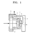
- FIG. 1 is a sketch showing the motor noise reduction system in conventional vacuum cleaners
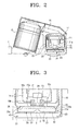
- FIG. 2 is a sectional view showing the motor noise reduction system in an embodiment of this invention
- FIG 3 is an expanded sectional view showing the mounted portion of the filter shown in FIG. 2,
- FIG. 4 is a side view showing a different embodiment of the filter of FIG. 2,
- FIG. 5 is a plan view showing the sliding door opened outwardly from the main body of the vacuum cleaner in FIG. 2,
- FIG 6 is a sectional view showing the suction path of the air in a vacuum cleaner containing a motor noise reduction system using an embodiment of this invention
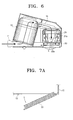
- FIGS. 7a and 7b are sectional views showing a different embodiment of the door supporting the filter member.
- FIG. 8 is a graph comparing the noise emission from vacuum cleaners with conventional motor noise reduction systems and those with an embodiment of the current invention.
- a suction part 11 which sucks the incoming dust into the dust collection chamber 13, through the suction nozzle and piping (not shown).
- the dust collection chamber 13 can adopt a cyclone airflow, taking into account the dust collection capacity, and dust-laden air enters in through the suction part 11 at the lower end of the chamber.
- a connecting channel 15 carrying the filtered air from the dust collection chamber 13 to the motor section 17, after the air has passed through a filter member (not shown) and the dust has been filtered from the air and collected in the dust collection chamber 13.
- the motor section 17 includes a motor 21 to provide suction, an inner casing 19 covering the motor, and an outer casing 20 simultaneously covering the inner casing and housing the motor mount 23.
- the inner casing 19 forms two layers, so on the sides and lower surface it is possible to have a plurality of first and second exhaust openings 19a, 19b, referring to FIG 3, able to reduce the noise. In this situation the inner casing 19 is not restricted in the manner described above, and it is even possible to omit the inner casing 19 and only make use of the outer casing 20.
- the outer casing 20 comprises a plurality of first exhaust openings 20a for discharging air that has passed through the second exhaust openings 19b of the inner casing 19 to the outside of the outer casing 20.
- the first exhaust openings 20a can be arranged freely on the lower surface of the outer casing 20, except for the area where the motor mount 23 is located.
- the mount part 25 inserted by a filter member 30 extends towards the outer edge of the lower surface as in FIG. 3.
- a cavity 26 may be formed along the inside circumference of the mount part 25, with a step 26a of a predetermined height. It is advisable that the height of the step 26a be determined by considering the exhaust capacity and filtering capacity together.
- the mount part 25 may also comprise a plurality of second exhaust openings 25a.
- the filter member 30 is supported by an outwardly openable sliding door located on one side of the housing of the vacuum cleaner.
- a predetermined space is formed between a seat 52 of the sliding door 50 and the filter member 30, and in order that air that has passed through the filter member 30 may be discharged within the main body 10 of the vacuum cleaner, it is advisable that a plurality of spacers 40 be connected to the surface of the filter 30 member.
- the spacers 40 in FIG 3 can maintain a space S of a predetermined height between the lower surface 33 of the filter member 30 and its seat 52 on the sliding door 50.
- the volume of the space S can be readily determined by setting the height of the spacers 40 separately, taking into consideration their filtering capacity and exhaust capacity.
- Either vibration-absorbent or sound-absorbent members of a predetermined consistency may be used, provided they are made of material of a consistency suitable for maintaining the predetermined space.
- said spacers 40 be attached independently to the lower surface 33 of the filter member 30, or for a plurality of support projections 37 to be integrally formed on the surface part of the filter 30, as in FIG. 4.
- the sliding door 50 is connected slidingly to the housing 10 of the vacuum cleaner, as shown in FIG. 5, and may slide open outwardly from the mount point 25, so the filter member 30 can be changed.
- the sliding door 50 comprises a sliding groove 51, referring to FIG. 3, on both sides, and individually inserted guide platforms on the housing 10.
- a sliding door is shown, but there are no restrictions on the type of door that may be used, and so it is also possible to use a door 50 attached to the housing with a hinge, as in FIG. 7a, or a door 50 attached to the housing 10 with screws 55, as in FIG. 7b.
- the spacers 40 may be designed in such a way they sit directly on the inside surface of the housing 10 of the vacuum cleaner.
- FIG. 6 is a sectional view showing an outline of the suction path of the air taken into the vacuum cleaner containing a motor noise reduction system implementing this invention.
- the air that has entered the motor section 17 passes through openings 21 a in the motor 21, and after passing successively through the first and second exhaust openings 19a, 19b in the inner casing 19, passes into the filter 30 through first exhaust openings 19a in the outer casing 20.
- the long exhaust channels used in the conventional technology between the outer casing 20 and the filter member 30 are omitted, and filtered air which has passed through the first exhaust openings 25a in the outer casing 20 of the motor and through the filter member 30 can be discharged directly, so the vibrations which are generated in the exhaust channels of conventional vacuum cleaners and the noise resulting from these can be eliminated.
- air that has passed through the filter member 30 passes through the second exhaust openings 25a of the mount part 25 and the spacers 40, and is discharged within the main body 10 of the vacuum cleaner in the space between the lower surface 33 of the filter member 30 and its seat on the sliding door.
- the air discharged through the filter member 30 travels in the direction of the dust-collecting chamber 13, but it is applicable to all cases where the air is discharged within the housing and not expelled directly from the vacuum cleaner.
- Air discharged within the main body 10 of the vacuum cleaner in this manner may be released to the outside of the vacuum cleaner through a grille, exhaust holes, or other means, which constitute part of the main body 10 of the vacuum cleaner.
- the filter member 30 comprises structures that are not attached to the main body 10 of the vacuum cleaner, so restrictions on the location of the grille or exhaust filters in conventional vacuum cleaners, requiring them to be mounted on the upper part of the main body 10 of the vacuum cleaner due to the placement of the filter, can be removed, and restrictions on adding to the design of the main body 10 of the vacuum cleaner can also be resolved.
- the motor axis is arranged perpendicularly to the main body 10 of the vacuum cleaner and the explanations assume the motor is installed in this manner. Comparing this arrangement with one in which the motor is installed horizontally relative to the housing, as shown in FIG. 8, consumers can notice a reduction in the peak of the motor rotation frequency of approximately 5dBA (a base contrast in the constituent motor rotation frequency of 5dBA is detectable to consumers). This difference in the noise level results more from the motor rotating along a vertical rather than a horizontal axis, instead of from the vibrations generated in a vertical motor arrangement.
- the long chambers located between the outer casing of the motor and the filter member in conventional vacuum cleaners are eliminated, and air that has passed through the filter from the exhaust holes on the outer casing of the motor can be discharged directly within the main body of the vacuum cleaner, so the vibrations which arise from passing through the confined exhaust chamber in conventional vacuum cleaners, and the noise resulting from this, are eliminated.
- the casing of the vacuum cleaner can be designed freely, without restrictions on the location of the grille or exhaust holes, due to the installation of the filter member on the lower outside of the outer casing of the main frame at the time of the design of the main frame, so the location of the filter member on the installed exhaust side is not connected to the main frame and the inside of the housing can be fixed in place.
Abstract
Description
- This invention relates to a vacuum cleaner, and more particularly to a vacuum cleaner incorporating a noise reduction system designed to reduce the noise generated by the discharge of exhaust air when the motor is in operation.
- Generally in vacuum cleaners exhaust noise is generated inside the housing when exhaust air is discharged from the motor. In order to solve this problem, exhaust air is conventionally discharged from the vacuum cleaner through a motor noise reduction system by the following process.
- As is illustrated in FIG. 1, exhaust air passes through an
opening 2a from the rear part of themotor 2 into thefirst exhaust channel 3. After then passing through thesecond exhaust channel 4, formed between the outer surface of theinner casing 6 of themotor 2 and the inner surface of the outer casing of the motor 1, exhaust air passes through anexhaust filter 5 installed on the inside of the a main body(not shown) of the vacuum cleaner, facing the upper surface of the outer casing, and is discharged from the vacuum cleaner. - When the exhaust air travels successively through the
first exhaust channel 3 and thesecond exhaust channel 4 in this manner, following a range of long or curved paths, the noise produced by themotor 2 can be reduced by increasing the length and modifying the course of the channels that it must travel through. - However, in the conventional technology, the exhaust air passes rapidly through the
exhaust channels inner casing 6 and outer casing 1 causing a vibration to develop, which is then transmitted to the a main body(not shown) of the vacuum cleaner and emitted into the environment. - In the conventional system there need to be long channels or short channels for the unfiltered exhaust air to travel through from the exhaust outlet of the outer casing to the exhaust filter of the main body of the vacuum cleaner, as described above, because unfiltered dust expelled from the outer casing of the motor cannot be discharged inside the vacuum cleaner, to avoid pollution from dust or other materials. Exhaust channels are required, but they cause vibrations to develop, as described above, and it is difficult to solve the problem of the noise that results from these vibrations.
- The aim of this invention is to provide a vacuum cleaner comprising an alternative motor noise reduction system that can eliminate vibrations arising in the exhaust chambers and the noise that results from them.
- In order to achieve the above aim, this invention provides a vacuum cleaner comprising a casing covering the motor, disposed on the inside of the housing, a removable filter member attached to the side of the motor casing, and a motor noise reduction system wherein the air discharged from the motor casing is released inside the housing of the vacuum cleaner through a filter member in the exhaust chamber.
- According to this invention, the vibrations that arise by the exhaust air passing through the exhaust chambers and the noise resulting from them can be greatly reduced by omitting the long curved exhaust chambers along the side of the motor casing.
- The filter member, by being disposed so as to leave a space between its lower surface and the inside surface of the housing, makes it possible to discharge filtered exhaust air within the vacuum cleaner.
- The motor casing may comprise a mount part housing the filter member on one side, a plurality of first exhaust openings on the upper surface of the mount part, and preferably also a plurality of second exhaust openings on one surface, to discharge air that has passed through the filter member.
- The motor casing may also comprise at least one spacer interposed between the lower surface of the filter member and the inside surface of the casing of the vacuum cleaner adjacent to the filter member, to preserve a space between the two surfaces, and in this situation either vibration-absorbent or sound-absorbent parts may be used.
- The vacuum cleaner may also comprise a door attached with a sliding mechanism to one side of the motor casing facing the lower surface of the filter member, and able to open outwards from the mount point of the filter member.
- FIG. 1 is a sketch showing the motor noise reduction system in conventional vacuum cleaners,
- FIG. 2 is a sectional view showing the motor noise reduction system in an embodiment of this invention,
- FIG 3 is an expanded sectional view showing the mounted portion of the filter shown in FIG. 2,
- FIG. 4 is a side view showing a different embodiment of the filter of FIG. 2,
- FIG. 5 is a plan view showing the sliding door opened outwardly from the main body of the vacuum cleaner in FIG. 2,
- FIG 6 is a sectional view showing the suction path of the air in a vacuum cleaner containing a motor noise reduction system using an embodiment of this invention,
- FIGS. 7a and 7b are sectional views showing a different embodiment of the door supporting the filter member, and
- FIG. 8 is a graph comparing the noise emission from vacuum cleaners with conventional motor noise reduction systems and those with an embodiment of the current invention.
- The composition of a vacuum cleaner containing a motor noise reduction system using an embodiment of this invention is described in detail below, referring to the attached drawings.
- Firstly, as in FIG 2, inside a
main body 10 of the vacuum cleaner is asuction part 11 which sucks the incoming dust into thedust collection chamber 13, through the suction nozzle and piping (not shown). Thedust collection chamber 13 can adopt a cyclone airflow, taking into account the dust collection capacity, and dust-laden air enters in through thesuction part 11 at the lower end of the chamber. - Also inside the housing is a connecting
channel 15 carrying the filtered air from thedust collection chamber 13 to themotor section 17, after the air has passed through a filter member (not shown) and the dust has been filtered from the air and collected in thedust collection chamber 13. - The
motor section 17 includes amotor 21 to provide suction, aninner casing 19 covering the motor, and anouter casing 20 simultaneously covering the inner casing and housing themotor mount 23. - The
inner casing 19 forms two layers, so on the sides and lower surface it is possible to have a plurality of first andsecond exhaust openings inner casing 19 is not restricted in the manner described above, and it is even possible to omit theinner casing 19 and only make use of theouter casing 20. - The
outer casing 20 comprises a plurality offirst exhaust openings 20a for discharging air that has passed through thesecond exhaust openings 19b of theinner casing 19 to the outside of theouter casing 20. Thefirst exhaust openings 20a can be arranged freely on the lower surface of theouter casing 20, except for the area where themotor mount 23 is located. - Also, giving an example of one aspect of the
outer casing 20, themount part 25 inserted by afilter member 30 extends towards the outer edge of the lower surface as in FIG. 3. In this situation, in order to have a space between thefilter member 30 and thefirst exhaust openings 20a, so that the air can be discharged smoothly through thefirst exhaust openings 20a toward thefilter member 30, acavity 26 may be formed along the inside circumference of themount part 25, with astep 26a of a predetermined height. It is advisable that the height of thestep 26a be determined by considering the exhaust capacity and filtering capacity together. - Moreover, in order for the air that has passed through the
filter member 30 to also be discharged from the side of thefilter member 30, themount part 25 may also comprise a plurality ofsecond exhaust openings 25a. - The
filter member 30 is supported by an outwardly openable sliding door located on one side of the housing of the vacuum cleaner. A predetermined space is formed between aseat 52 of the slidingdoor 50 and thefilter member 30, and in order that air that has passed through thefilter member 30 may be discharged within themain body 10 of the vacuum cleaner, it is advisable that a plurality ofspacers 40 be connected to the surface of thefilter 30 member. - In this situation, the
spacers 40 in FIG 3 can maintain a space S of a predetermined height between thelower surface 33 of thefilter member 30 and itsseat 52 on the slidingdoor 50. The volume of the space S can be readily determined by setting the height of thespacers 40 separately, taking into consideration their filtering capacity and exhaust capacity. Either vibration-absorbent or sound-absorbent members of a predetermined consistency may be used, provided they are made of material of a consistency suitable for maintaining the predetermined space. - Also, in order to ensure the space S is preserved, it is possible either that said
spacers 40 be attached independently to thelower surface 33 of thefilter member 30, or for a plurality ofsupport projections 37 to be integrally formed on the surface part of thefilter 30, as in FIG. 4. - The sliding
door 50 is connected slidingly to thehousing 10 of the vacuum cleaner, as shown in FIG. 5, and may slide open outwardly from themount point 25, so thefilter member 30 can be changed. In this situation, the slidingdoor 50 comprises asliding groove 51, referring to FIG. 3, on both sides, and individually inserted guide platforms on thehousing 10. - In the embodiment described here a sliding door is shown, but there are no restrictions on the type of door that may be used, and so it is also possible to use a
door 50 attached to the housing with a hinge, as in FIG. 7a, or adoor 50 attached to thehousing 10 withscrews 55, as in FIG. 7b. Likewise, thespacers 40 may be designed in such a way they sit directly on the inside surface of thehousing 10 of the vacuum cleaner. - The operation and effectiveness of a vacuum cleaner with a motor noise reduction system using an embodiment of this invention as described above can be explained as follows.
- FIG. 6 is a sectional view showing an outline of the suction path of the air taken into the vacuum cleaner containing a motor noise reduction system implementing this invention.
- If the
motor 21 rotates as shown in FIG. 6, air in the vicinity of the suction nozzle (not shown) is sucked into the cyclonicdust collection chamber 13 together with dust to be removed. The air enters themotor section 17 through the connectingchannel 15, after the dust has been removed by the centrifugal force of the cyclonicdust collection chamber 13, and it has passed through a filter (not shown). - The air that has entered the
motor section 17 passes throughopenings 21 a in themotor 21, and after passing successively through the first andsecond exhaust openings inner casing 19, passes into thefilter 30 throughfirst exhaust openings 19a in theouter casing 20. - In this situation, in the embodiment of this invention, the long exhaust channels used in the conventional technology between the
outer casing 20 and thefilter member 30 are omitted, and filtered air which has passed through thefirst exhaust openings 25a in theouter casing 20 of the motor and through thefilter member 30 can be discharged directly, so the vibrations which are generated in the exhaust channels of conventional vacuum cleaners and the noise resulting from these can be eliminated. - Subsequently, air that has passed through the
filter member 30 passes through thesecond exhaust openings 25a of themount part 25 and thespacers 40, and is discharged within themain body 10 of the vacuum cleaner in the space between thelower surface 33 of thefilter member 30 and its seat on the sliding door. In this embodiment, the air discharged through thefilter member 30 travels in the direction of the dust-collecting chamber 13, but it is applicable to all cases where the air is discharged within the housing and not expelled directly from the vacuum cleaner. - Air discharged within the
main body 10 of the vacuum cleaner in this manner may be released to the outside of the vacuum cleaner through a grille, exhaust holes, or other means, which constitute part of themain body 10 of the vacuum cleaner. - In this embodiment of the invention, the
filter member 30 comprises structures that are not attached to themain body 10 of the vacuum cleaner, so restrictions on the location of the grille or exhaust filters in conventional vacuum cleaners, requiring them to be mounted on the upper part of themain body 10 of the vacuum cleaner due to the placement of the filter, can be removed, and restrictions on adding to the design of themain body 10 of the vacuum cleaner can also be resolved. - In this embodiment of the invention, the motor axis is arranged perpendicularly to the
main body 10 of the vacuum cleaner and the explanations assume the motor is installed in this manner. Comparing this arrangement with one in which the motor is installed horizontally relative to the housing, as shown in FIG. 8, consumers can notice a reduction in the peak of the motor rotation frequency of approximately 5dBA (a base contrast in the constituent motor rotation frequency of 5dBA is detectable to consumers). This difference in the noise level results more from the motor rotating along a vertical rather than a horizontal axis, instead of from the vibrations generated in a vertical motor arrangement. - With this invention, the long chambers located between the outer casing of the motor and the filter member in conventional vacuum cleaners are eliminated, and air that has passed through the filter from the exhaust holes on the outer casing of the motor can be discharged directly within the main body of the vacuum cleaner, so the vibrations which arise from passing through the confined exhaust chamber in conventional vacuum cleaners, and the noise resulting from this, are eliminated.
- In addition to this, the casing of the vacuum cleaner can be designed freely, without restrictions on the location of the grille or exhaust holes, due to the installation of the filter member on the lower outside of the outer casing of the main frame at the time of the design of the main frame, so the location of the filter member on the installed exhaust side is not connected to the main frame and the inside of the housing can be fixed in place.
- Although the preferred embodiments of the present invention have been described in order to illustrate the theory, it is not limited to the organization and implementation explained and illustrated above. Rather it is written so that the changes and improvements of this invention will be able to be readily understood by those skilled in the art, without deviating from the spirit and scope of the attached patent request. Therefore these changes and improvements must be considered together with the features that have not changed from the conventional technology.
Claims (18)
- A vacuum cleaner with a motor noise reduction system, comprising:a motor casing, positioned inside a main body of the vacuum cleaner, covering a motor; anda filter member removably fastened to a side of the motor casing;wherein air from within the motor casing is discharged within the main body of the vacuum cleaner through the filter member.
- The vacuum cleaner with a motor noise reduction system according to any of claims 1 and 2, wherein the filter member is arranged in such a way as to leave a space between a surface of the filter member and an inside surface of the main body of the vacuum cleaner.
- The vacuum cleaner with a motor noise reduction system according to any of claims 1 and 2, wherein the motor casing further comprises a mount part accommodating the filter member on one side of the motor casing.
- The vacuum cleaner with a motor noise reduction system according to claim 3, wherein the mount part further comprises:a plurality of first exhaust openings on an upper surface; anda plurality of second exhaust openings on another surface, to discharge air that has passed through the filter member.
- The vacuum cleaner with a motor noise reduction system according to any of claims 1 to 4, wherein the filter member comprises one or more support projections integrally formed on a lower surface of the filter member.
- The vacuum cleaner with a motor noise reduction system according to any of claims 1 to 5, further comprising one or more spacers interposed between a lower surface of the filter member and an inside surface of a main body of the vacuum cleaner facing the lower surface of the filter member.
- The vacuum cleaner with a motor noise reduction system according to claim 6, wherein the spacers are vibration-absorbent members or sound-absorbent members.
- The vacuum cleaner with a motor noise reduction system according to any of claims 1 to 7, further comprising a door installed on part of the main body of the vacuum cleaner facing a lower surface of the filter member, which opens outwardly from a mount part to an exterior of the vacuum cleaner.
- The vacuum cleaner with a motor noise reduction system according to claim 8, wherein the door is attached to the main body of the vacuum cleaner with a sliding mechanism on both sides of the housing of the vacuum cleaner.
- The vacuum cleaner with a motor noise reduction system according to claim 8, wherein the door is attached with a hinge mechanism to one side of the main body of the vacuum cleaner.
- The vacuum cleaner with a motor noise reduction system according to claim 8, wherein the door is attached by screws to one side of the main body of the vacuum cleaner.
- A motor noise reduction system for a vacuum cleaner, comprising:a motor casing, positionable inside a main body of the vacuum cleaner, covering a motor; anda filter member removably fastened to a side of the motor casing;wherein air from within the motor casing is discharged within the main body of the vacuum cleaner through the filter member.
- The motor noise reduction system according to claim 12, wherein the filter member is arranged in such a way as to leave a space between a surface of the filter member and an inside surface of the housing.
- The motor noise reduction system according to any of claims 12 and 13, wherein the motor casing further comprises a mount part accommodating the filter member on one side of the motor casing.
- The motor noise reduction system according to claim 14, wherein the mount part further comprises:a plurality of first exhaust openings on an upper surface; anda plurality of second exhaust openings on another surface, to discharge air that has passed through the filter member.
- The motor noise reduction system according to any of claims 12 to 15,
wherein the filter member comprises one or more support projections integrally formed on a lower surface of the filter member. - The motor noise reduction system according to any of claims 12 to 16, further comprising one or more spacers interposed between a lower surface of the filter member and an inside surface of a main body of the vacuum cleaner facing the lower surface of the filter member.
- The motor noise reduction system according to claim 17, wherein the spacers are vibration-absorbent members or sound-absorbent members.
Applications Claiming Priority (1)
| Application Number | Priority Date | Filing Date | Title |
|---|---|---|---|
| KR1020050123765A KR100725515B1 (en) | 2005-12-15 | 2005-12-15 | Vacuum cleaner having noise reducing structure of motor |
Publications (3)
| Publication Number | Publication Date |
|---|---|
| EP1797808A2 true EP1797808A2 (en) | 2007-06-20 |
| EP1797808A3 EP1797808A3 (en) | 2008-08-06 |
| EP1797808B1 EP1797808B1 (en) | 2010-11-10 |
Family
ID=37133895
Family Applications (1)
| Application Number | Title | Priority Date | Filing Date |
|---|---|---|---|
| EP06291439A Expired - Fee Related EP1797808B1 (en) | 2005-12-15 | 2006-09-12 | Vacuum cleaner having a motor noise reduction system |
Country Status (6)
| Country | Link |
|---|---|
| US (1) | US20070136982A1 (en) |
| EP (1) | EP1797808B1 (en) |
| KR (1) | KR100725515B1 (en) |
| CN (1) | CN1981690A (en) |
| AU (1) | AU2006213954A1 (en) |
| RU (1) | RU2337604C2 (en) |
Cited By (3)
| Publication number | Priority date | Publication date | Assignee | Title |
|---|---|---|---|---|
| EP1952742A2 (en) * | 2007-02-05 | 2008-08-06 | Samsung Gwangju Electronics Co., Ltd. | Motor assembly and vacuum cleaner having the same |
| EP1803382A3 (en) * | 2005-12-27 | 2008-09-03 | Samsung Electronics Co., Ltd. | Vacuum cleaner and method for reducing noise generated thereby |
| WO2020078564A1 (en) | 2018-10-19 | 2020-04-23 | Alfred Kärcher SE & Co. KG | Suction machine with sound-angle element |
Families Citing this family (7)
| Publication number | Priority date | Publication date | Assignee | Title |
|---|---|---|---|---|
| KR100837362B1 (en) * | 2006-10-31 | 2008-06-12 | 삼성광주전자 주식회사 | Noise Absorbing Apparatus of Motor for Vacuum Cleaner |
| KR101436631B1 (en) * | 2007-11-19 | 2014-09-01 | 엘지전자 주식회사 | Vacuum cleaner |
| CN104414587A (en) * | 2013-09-06 | 2015-03-18 | 江苏美的春花电器股份有限公司 | Dust collector and air inlet device of dust collector |
| KR101509738B1 (en) * | 2014-10-27 | 2015-04-14 | 주식회사코네트인더스트리 | Dust-container assembly of vacuum cleaner |
| KR102549125B1 (en) * | 2016-06-10 | 2023-06-30 | 삼성전자주식회사 | Robot cleaner |
| KR102492164B1 (en) | 2016-07-22 | 2023-01-30 | 삼성전자주식회사 | Vacuum cleaner |
| CN108209701B (en) * | 2018-04-04 | 2023-11-28 | 小狗电器互联网科技(北京)股份有限公司 | Dust collector and air duct structure thereof |
Citations (1)
| Publication number | Priority date | Publication date | Assignee | Title |
|---|---|---|---|---|
| EP1547508A2 (en) | 2003-12-24 | 2005-06-29 | Daewoo Electronics Corporation | Vacuum cleaner |
Family Cites Families (10)
| Publication number | Priority date | Publication date | Assignee | Title |
|---|---|---|---|---|
| DE3443837A1 (en) * | 1984-11-30 | 1986-06-05 | Progress-Elektrogeräte Mauz & Pfeiffer GmbH & Co, 7000 Stuttgart | VACUUM CLEANER |
| DE3815321C2 (en) * | 1988-05-05 | 1994-06-16 | Licentia Gmbh | vacuum cleaner |
| KR930001867A (en) * | 1991-07-26 | 1993-02-22 | 배순훈 | Low noise vacuum cleaner |
| US5479676A (en) * | 1994-05-12 | 1996-01-02 | Electrolux Corporation | Vacuum cleaner |
| KR970009718A (en) * | 1995-08-31 | 1997-03-27 | 배순훈 | Sound absorption room which lengthened exhaust channel of vacuum cleaner |
| KR100205687B1 (en) | 1997-08-30 | 1999-07-01 | 구자홍 | The exhaust structure of the vacuum cleaner |
| KR20000007112U (en) * | 1998-09-26 | 2000-04-25 | 전주범 | Exhaust vent structure of vacuum cleaner |
| US7614113B2 (en) * | 2003-07-31 | 2009-11-10 | Panasonic Corporation Of North America | Motor enclosure for a vacuum cleaner |
| US7351269B2 (en) * | 2003-12-22 | 2008-04-01 | Lau Kwok Yau | Self cleaning filter and vacuum incorporating same |
| KR100602239B1 (en) | 2003-12-24 | 2006-07-19 | 주식회사 대우일렉트로닉스 | Exhaust air guide for the vacuum cleaner |
-
2005
- 2005-12-15 KR KR1020050123765A patent/KR100725515B1/en not_active IP Right Cessation
-
2006
- 2006-08-23 US US11/508,220 patent/US20070136982A1/en not_active Abandoned
- 2006-09-12 EP EP06291439A patent/EP1797808B1/en not_active Expired - Fee Related
- 2006-09-14 AU AU2006213954A patent/AU2006213954A1/en not_active Abandoned
- 2006-09-29 RU RU2006134480/12A patent/RU2337604C2/en not_active IP Right Cessation
- 2006-09-29 CN CNA2006101414743A patent/CN1981690A/en active Pending
Patent Citations (1)
| Publication number | Priority date | Publication date | Assignee | Title |
|---|---|---|---|---|
| EP1547508A2 (en) | 2003-12-24 | 2005-06-29 | Daewoo Electronics Corporation | Vacuum cleaner |
Cited By (5)
| Publication number | Priority date | Publication date | Assignee | Title |
|---|---|---|---|---|
| EP1803382A3 (en) * | 2005-12-27 | 2008-09-03 | Samsung Electronics Co., Ltd. | Vacuum cleaner and method for reducing noise generated thereby |
| US7774898B2 (en) | 2005-12-27 | 2010-08-17 | Samsung Electronics Co., Ltd. | Vacuum cleaner and method for reducing noise generated thereby |
| EP1952742A2 (en) * | 2007-02-05 | 2008-08-06 | Samsung Gwangju Electronics Co., Ltd. | Motor assembly and vacuum cleaner having the same |
| EP1952742A3 (en) * | 2007-02-05 | 2009-12-23 | Samsung Gwangju Electronics Co., Ltd. | Motor assembly and vacuum cleaner having the same |
| WO2020078564A1 (en) | 2018-10-19 | 2020-04-23 | Alfred Kärcher SE & Co. KG | Suction machine with sound-angle element |
Also Published As
| Publication number | Publication date |
|---|---|
| RU2337604C2 (en) | 2008-11-10 |
| EP1797808A3 (en) | 2008-08-06 |
| RU2006134480A (en) | 2008-04-10 |
| KR100725515B1 (en) | 2007-06-08 |
| AU2006213954A1 (en) | 2007-07-05 |
| US20070136982A1 (en) | 2007-06-21 |
| CN1981690A (en) | 2007-06-20 |
| EP1797808B1 (en) | 2010-11-10 |
Similar Documents
| Publication | Publication Date | Title |
|---|---|---|
| EP1797808B1 (en) | Vacuum cleaner having a motor noise reduction system | |
| KR101353311B1 (en) | Vacuum Cleaner | |
| US7275281B2 (en) | Motor assembly and vacuum cleaner having the same | |
| JP3012729B2 (en) | Vacuum cleaner | |
| US7596829B2 (en) | Vacuum cleaner | |
| EP1929914B1 (en) | Fan motor case assembly for noise reduction | |
| JPH0966007A (en) | Vacuum cleaner with noise reduction system | |
| US5991969A (en) | Noise absorbing device for vacuum cleaner | |
| US7690077B2 (en) | Central vacuum units with an acoustic damping pathway | |
| KR100809738B1 (en) | Vacuum cleaner | |
| US7615090B2 (en) | Compact central vacuum unit | |
| CN104159488B (en) | Electric dust collector | |
| KR100349292B1 (en) | Electric cleaner | |
| KR101480304B1 (en) | Cyclone dust collector and vacuum cleaner | |
| CN216557295U (en) | Noise-reduction type range hood | |
| CN218359297U (en) | Vertical biological safety cabinet | |
| CN220832887U (en) | Hair collecting device | |
| KR20000007104U (en) | Noise reduction structure of the vacuum cleaner sound absorption case | |
| KR100213365B1 (en) | Device for decreasing the noise of vacuum cleaner | |
| KR100677878B1 (en) | Vacuum cleaner | |
| KR100270801B1 (en) | A noise absorption device of a vacuum cleaner | |
| KR100270800B1 (en) | A noise decreasing device of a vacuum cleaner | |
| KR100231436B1 (en) | MCS(Muffler Chamber System) of Vacuum Cleaner | |
| KR20060062238A (en) | Vibration prevention structure of exhaust filter for a vacuum cleaner | |
| KR19980075351A (en) | Noise prevention structure of vacuum cleaner driving motor |
Legal Events
| Date | Code | Title | Description |
|---|---|---|---|
| PUAI | Public reference made under article 153(3) epc to a published international application that has entered the european phase |
Free format text: ORIGINAL CODE: 0009012 |
|
| AK | Designated contracting states |
Kind code of ref document: A2 Designated state(s): AT BE BG CH CY CZ DE DK EE ES FI FR GB GR HU IE IS IT LI LT LU LV MC NL PL PT RO SE SI SK TR |
|
| AX | Request for extension of the european patent |
Extension state: AL BA HR MK YU |
|
| PUAL | Search report despatched |
Free format text: ORIGINAL CODE: 0009013 |
|
| AK | Designated contracting states |
Kind code of ref document: A3 Designated state(s): AT BE BG CH CY CZ DE DK EE ES FI FR GB GR HU IE IS IT LI LT LU LV MC NL PL PT RO SE SI SK TR |
|
| AX | Request for extension of the european patent |
Extension state: AL BA HR MK RS |
|
| 17P | Request for examination filed |
Effective date: 20090203 |
|
| AKX | Designation fees paid |
Designated state(s): FR GB |
|
| REG | Reference to a national code |
Ref country code: DE Ref legal event code: 8566 |
|
| GRAP | Despatch of communication of intention to grant a patent |
Free format text: ORIGINAL CODE: EPIDOSNIGR1 |
|
| GRAS | Grant fee paid |
Free format text: ORIGINAL CODE: EPIDOSNIGR3 |
|
| GRAA | (expected) grant |
Free format text: ORIGINAL CODE: 0009210 |
|
| AK | Designated contracting states |
Kind code of ref document: B1 Designated state(s): FR GB |
|
| REG | Reference to a national code |
Ref country code: GB Ref legal event code: FG4D |
|
| PLBE | No opposition filed within time limit |
Free format text: ORIGINAL CODE: 0009261 |
|
| STAA | Information on the status of an ep patent application or granted ep patent |
Free format text: STATUS: NO OPPOSITION FILED WITHIN TIME LIMIT |
|
| REG | Reference to a national code |
Ref country code: FR Ref legal event code: TP Owner name: SAMSUNG ELECTRONICS CO., LTD., KR Effective date: 20110826 |
|
| 26N | No opposition filed |
Effective date: 20110811 |
|
| REG | Reference to a national code |
Ref country code: FR Ref legal event code: PLFP Year of fee payment: 11 |
|
| REG | Reference to a national code |
Ref country code: FR Ref legal event code: PLFP Year of fee payment: 12 |
|
| REG | Reference to a national code |
Ref country code: FR Ref legal event code: PLFP Year of fee payment: 13 |
|
| PGFP | Annual fee paid to national office [announced via postgrant information from national office to epo] |
Ref country code: FR Payment date: 20180822 Year of fee payment: 13 |
|
| PGFP | Annual fee paid to national office [announced via postgrant information from national office to epo] |
Ref country code: GB Payment date: 20180822 Year of fee payment: 13 |
|
| GBPC | Gb: european patent ceased through non-payment of renewal fee |
Effective date: 20190912 |
|
| PG25 | Lapsed in a contracting state [announced via postgrant information from national office to epo] |
Ref country code: FR Free format text: LAPSE BECAUSE OF NON-PAYMENT OF DUE FEES Effective date: 20190930 Ref country code: GB Free format text: LAPSE BECAUSE OF NON-PAYMENT OF DUE FEES Effective date: 20190912 |