EP1797379B1 - Cryo-device and associated operational method - Google Patents
Cryo-device and associated operational method Download PDFInfo
- Publication number
- EP1797379B1 EP1797379B1 EP05794677A EP05794677A EP1797379B1 EP 1797379 B1 EP1797379 B1 EP 1797379B1 EP 05794677 A EP05794677 A EP 05794677A EP 05794677 A EP05794677 A EP 05794677A EP 1797379 B1 EP1797379 B1 EP 1797379B1
- Authority
- EP
- European Patent Office
- Prior art keywords
- sample
- temperature
- cooling chamber
- sample container
- cryo
- Prior art date
- Legal status (The legal status is an assumption and is not a legal conclusion. Google has not performed a legal analysis and makes no representation as to the accuracy of the status listed.)
- Active
Links
- 238000000034 method Methods 0.000 title claims description 30
- 239000000523 sample Substances 0.000 claims abstract description 212
- 238000001816 cooling Methods 0.000 claims abstract description 122
- 238000007710 freezing Methods 0.000 claims abstract description 52
- 230000008014 freezing Effects 0.000 claims abstract description 52
- 238000010257 thawing Methods 0.000 claims abstract description 50
- 239000012472 biological sample Substances 0.000 claims abstract description 16
- 238000011017 operating method Methods 0.000 claims abstract description 13
- 238000005138 cryopreservation Methods 0.000 claims abstract description 8
- 238000013517 stratification Methods 0.000 claims description 13
- 238000010438 heat treatment Methods 0.000 claims description 10
- 230000001681 protective effect Effects 0.000 claims description 10
- 238000003780 insertion Methods 0.000 claims description 6
- 230000037431 insertion Effects 0.000 claims description 6
- 230000001105 regulatory effect Effects 0.000 claims description 4
- 239000004020 conductor Substances 0.000 claims description 2
- 238000000605 extraction Methods 0.000 claims 1
- IJGRMHOSHXDMSA-UHFFFAOYSA-N Atomic nitrogen Chemical compound N#N IJGRMHOSHXDMSA-UHFFFAOYSA-N 0.000 description 16
- 230000002123 temporal effect Effects 0.000 description 13
- 239000002826 coolant Substances 0.000 description 9
- 239000012520 frozen sample Substances 0.000 description 9
- 229910052757 nitrogen Inorganic materials 0.000 description 8
- 239000000463 material Substances 0.000 description 7
- 239000007788 liquid Substances 0.000 description 6
- 238000012546 transfer Methods 0.000 description 5
- 101100180314 Saccharomyces cerevisiae (strain ATCC 204508 / S288c) IST2 gene Proteins 0.000 description 4
- 230000006735 deficit Effects 0.000 description 4
- 101001050487 Homo sapiens IST1 homolog Proteins 0.000 description 3
- 102100023423 IST1 homolog Human genes 0.000 description 3
- 230000002277 temperature effect Effects 0.000 description 3
- RYGMFSIKBFXOCR-UHFFFAOYSA-N Copper Chemical compound [Cu] RYGMFSIKBFXOCR-UHFFFAOYSA-N 0.000 description 2
- 230000001276 controlling effect Effects 0.000 description 2
- 229910052802 copper Inorganic materials 0.000 description 2
- 239000010949 copper Substances 0.000 description 2
- 230000007423 decrease Effects 0.000 description 2
- 238000004321 preservation Methods 0.000 description 2
- 238000011179 visual inspection Methods 0.000 description 2
- 230000033228 biological regulation Effects 0.000 description 1
- 238000009835 boiling Methods 0.000 description 1
- 230000015556 catabolic process Effects 0.000 description 1
- 230000006378 damage Effects 0.000 description 1
- 238000006731 degradation reaction Methods 0.000 description 1
- 230000001419 dependent effect Effects 0.000 description 1
- 238000011161 development Methods 0.000 description 1
- 230000018109 developmental process Effects 0.000 description 1
- 210000002257 embryonic structure Anatomy 0.000 description 1
- 238000005516 engineering process Methods 0.000 description 1
- 230000009027 insemination Effects 0.000 description 1
- 239000011810 insulating material Substances 0.000 description 1
- 238000009413 insulation Methods 0.000 description 1
- 238000012986 modification Methods 0.000 description 1
- 230000004048 modification Effects 0.000 description 1
- 238000011160 research Methods 0.000 description 1
- 230000009303 sperm storage Effects 0.000 description 1
- 210000000130 stem cell Anatomy 0.000 description 1
- 238000005496 tempering Methods 0.000 description 1
- 230000003685 thermal hair damage Effects 0.000 description 1
Images


Classifications
-
- A—HUMAN NECESSITIES
- A01—AGRICULTURE; FORESTRY; ANIMAL HUSBANDRY; HUNTING; TRAPPING; FISHING
- A01N—PRESERVATION OF BODIES OF HUMANS OR ANIMALS OR PLANTS OR PARTS THEREOF; BIOCIDES, e.g. AS DISINFECTANTS, AS PESTICIDES OR AS HERBICIDES; PEST REPELLANTS OR ATTRACTANTS; PLANT GROWTH REGULATORS
- A01N1/00—Preservation of bodies of humans or animals, or parts thereof
- A01N1/02—Preservation of living parts
- A01N1/0236—Mechanical aspects
- A01N1/0242—Apparatuses, i.e. devices used in the process of preservation of living parts, such as pumps, refrigeration devices or any other devices featuring moving parts and/or temperature controlling components
- A01N1/0252—Temperature controlling refrigerating apparatus, i.e. devices used to actively control the temperature of a designated internal volume, e.g. refrigerators, freeze-drying apparatus or liquid nitrogen baths
- A01N1/0257—Stationary or portable vessels generating cryogenic temperatures
-
- F—MECHANICAL ENGINEERING; LIGHTING; HEATING; WEAPONS; BLASTING
- F25—REFRIGERATION OR COOLING; COMBINED HEATING AND REFRIGERATION SYSTEMS; HEAT PUMP SYSTEMS; MANUFACTURE OR STORAGE OF ICE; LIQUEFACTION SOLIDIFICATION OF GASES
- F25D—REFRIGERATORS; COLD ROOMS; ICE-BOXES; COOLING OR FREEZING APPARATUS NOT OTHERWISE PROVIDED FOR
- F25D3/00—Devices using other cold materials; Devices using cold-storage bodies
- F25D3/10—Devices using other cold materials; Devices using cold-storage bodies using liquefied gases, e.g. liquid air
-
- G—PHYSICS
- G01—MEASURING; TESTING
- G01N—INVESTIGATING OR ANALYSING MATERIALS BY DETERMINING THEIR CHEMICAL OR PHYSICAL PROPERTIES
- G01N1/00—Sampling; Preparing specimens for investigation
- G01N1/28—Preparing specimens for investigation including physical details of (bio-)chemical methods covered elsewhere, e.g. G01N33/50, C12Q
- G01N1/42—Low-temperature sample treatment, e.g. cryofixation
-
- F—MECHANICAL ENGINEERING; LIGHTING; HEATING; WEAPONS; BLASTING
- F25—REFRIGERATION OR COOLING; COMBINED HEATING AND REFRIGERATION SYSTEMS; HEAT PUMP SYSTEMS; MANUFACTURE OR STORAGE OF ICE; LIQUEFACTION SOLIDIFICATION OF GASES
- F25D—REFRIGERATORS; COLD ROOMS; ICE-BOXES; COOLING OR FREEZING APPARATUS NOT OTHERWISE PROVIDED FOR
- F25D2600/00—Control issues
- F25D2600/06—Controlling according to a predetermined profile
-
- F—MECHANICAL ENGINEERING; LIGHTING; HEATING; WEAPONS; BLASTING
- F25—REFRIGERATION OR COOLING; COMBINED HEATING AND REFRIGERATION SYSTEMS; HEAT PUMP SYSTEMS; MANUFACTURE OR STORAGE OF ICE; LIQUEFACTION SOLIDIFICATION OF GASES
- F25D—REFRIGERATORS; COLD ROOMS; ICE-BOXES; COOLING OR FREEZING APPARATUS NOT OTHERWISE PROVIDED FOR
- F25D2700/00—Means for sensing or measuring; Sensors therefor
- F25D2700/16—Sensors measuring the temperature of products
Definitions
- the invention relates to a cryogenic device for freezing and thawing a sample, in particular in the cryopreservation of a biological sample, as well as an associated operating method according to the preamble of the independent claims.
- cryopreservation biological samples are frozen vitality and later thawed vitality when needed again.
- applications for such a cryopreservation include the storage of embryos for stem cell research or the storage of sperm for later artificial insemination. It is important for the preservation of vitality in cryopreservation that a predetermined temporal temperature profile is observed both during freezing and when thawing the biological samples.
- freezers which use mostly liquid nitrogen with a boiling point of -196 ° C and have a cooling space in which the temperature can be adjusted by controlling the supply of the coolant to the desired temporal temperature profile when freezing or thawing biological samples to achieve.
- the biological samples When freezing the biological samples, these are introduced into the cold room of the automatic freezer and then cooled according to the predetermined temporal temperature profile from a start temperature of a freezing process to a target temperature of the freezing process. After reaching the target temperature of the freezing process, the frozen biological samples are then removed from the refrigerator of the freezer and stored for example in a cryogenic tank.
- thawing frozen biological samples When thawing frozen biological samples, for example, they are removed from a cryotank and introduced into the cold room of the automatic freezer. Subsequently, the temperature of the frozen biological sample is raised in accordance with a predetermined temporal temperature profile from a certain starting temperature of a thawing process up to a target temperature of the thawing process. After reaching the target temperature of the thawing process, the thawed sample is removed from the refrigerator of the automatic freezer and used again.
- a disadvantage of the above-described known automatic freezers is that the sample is exposed to undesirable temperature influences during introduction into the cold room and during removal from the cold room, which can thermally damage the biological sample and impair the goal of maintaining vitality.
- a disadvantage of the known freezers described above is still the unsatisfactory accuracy in setting the predetermined temporal temperature profile during freezing or thawing, which is caused by the relatively large volume of the refrigerator and the associated control problems.
- US 4,783,973 discloses a cryogenic device with a coolable cooling chamber with a arranged in the refrigerator sample container for receiving the sample, wherein the sample container is controlled by a resistance heating separately from the cooling space.
- the sample container is not used for temporary admission of the sample during freezing or thawing, but for storage of the sample in the frozen state.
- this document does not disclose a thermally insulated, removable transport container which serves to introduce or remove the sample from the cold room.
- US Pat. No. 6,065,294 discloses a transport container which can be inserted or removed from a cold room. From this document, however, not known to additionally provide a separate sample container for freezing or thawing the sample.
- the invention is therefore based on the object to provide an improved cryogen for freezing and / or thawing a sample and a corresponding operating method.
- the invention comprises the general technical teaching of arranging in the relatively large cooling space of a cryogen (for example a freezer) a sample container in which the sample is frozen and / or thawed, the sample container being temperature-controlled separately from the cooling space. This means that different temperatures can be set in the sample container and in the cold room.
- a cryogen for example a freezer
- the separate adjustability of the temperature in the sample container offers the advantage that the important for the vitality preservation of the biological sample temporal temperature course during freezing or thawing must be set only for the smaller volume within the sample container, which is technically much more possible than the control technology exact temperature control of the entire refrigerator of the automatic freezer.
- the separate adjustability of the temperature in the sample container independently of the other refrigerator offers the advantage that the above-described disturbing and vitalticiansSdigenden temperature effects can be avoided during insertion and removal of the sample, resulting from deviations from the predetermined start or target temperature ,
- a removable, thermally insulated transport container is arranged in the cold room to remove the sample from the refrigerator after freezing or to introduce it into the cold room for thawing.
- the sample is then removed from the transport container and transferred to the sample container, where the sample is thawed.
- the sample is removed from the sample container at the end of a freezing process and transferred to the transport container, which can then be removed from the cold room and stored, for example, in a cryotank
- the cryogenic device according to the invention preferably has a lifting device, by means of which the sample container in the cooling space can be controlled or lowered lowered and / or raised.
- this vertical movement of the sample container in the cold room enables consideration of the vertical temperature stratification in the cold room.
- the temperature in the cold room decreases from top to bottom, so that the sample container is preferably lowered at the end of a freezing process, so that the frozen sample can be removed without disturbing temperature effects of the surrounding medium within the cold room.
- the sample container is preferably in a raised position in order to avoid the thawed sample without disturbing temperature effects of the extremely cold medium located at the bottom of the cold room.
- the vertical movement of the sample container by the lifting device in a variant of the invention allows a tempering of the sample container by the sample container is raised or lowered according to the desired temperature within the vertical temperature stratification in the refrigerator.
- the sample container can thus be tempered separately from the cooling space without a separate cooling device by the sample container is raised or lowered accordingly.
- the sample container has a temperature sensor which measures the temperature in the sample container or at the level of the sample container or below or above, so that the vertical movement of the sample container can be temperature-dependent controlled in the refrigerator.
- a plurality of temperature sensors are mounted on the sample container at different vertical distances from the sample container, which makes it possible to determine a local vertical temperature gradient.
- the regulation of the upward or downward movement of the sample container can then react very sensitively to local temperature fluctuations in the cooling space.
- the sample container is arranged stationary in the cold room, wherein the sample container is preferably located at the bottom of the refrigerator.
- the temperature change at the opening of the sample container is not achieved by an increase or decrease of the sample container, but can be realized for example by a heater that heats the refrigerator, the heater preferably only heats an upper portion of the refrigerator.
- the heater is then preferably turned on when a sample is to be introduced into the sample container at the beginning of a freezing process or when the sample is removed from the sample container at the end of a thawing process.
- the heating of the upper region of the cooling space then advantageously prevents a disturbing thermal impairment of the sample during insertion or during the removal of the sample.
- the heater is preferably turned off when the sample is removed from the sample container at the end of a freezing process, or when the sample is introduced into the sample container at the beginning of a thawing process. The shutdown of the heater then also prevents the frozen sample is thermally damaged during insertion or removal.
- the cold room there is a vertical temperature stratification with a lower cold layer and an upper one Warm layer.
- a vertical temperature stratification with a lower cold layer and an upper one Warm layer.
- the heat layer preferably has a temperature that substantially corresponds to a predetermined start temperature of a freezing process or a predetermined target temperature of a thawing process, while the cold layer has a temperature substantially a predetermined target temperature of the freezing process or a predetermined Start temperature of the thawing process corresponds.
- the sample container is thermally insulated and has a lid which can be opened to remove the sample and to introduce the sample.
- the thermal insulation of the sample container is important if the temperature of the sample container is actively carried out by cooling and / or heating, since the temperature setting in the sample container is then only minimally affected by the ambient temperature within the cold room.
- the sample container it is alternatively also possible for the sample container to be thermally uninsulated relative to the cooling space. This is particularly useful when the temperature of the sample container is not active by a heating or cooling device takes place, but by a vertical movement of the sample container within the vertical temperature stratification of the refrigerator, as already explained above.
- At least one substantially vertically extending shaft with a wall made of a thermally conductive material is arranged in the cooling space, wherein the sample container is vertically movable in the shaft.
- the good thermal conductivity of the shaft wall advantageously leads to an approximately constant vertical temperature gradient in the shaft, so that each height in the shaft can be assigned a specific temperature. This advantageously makes it possible to dispense with temperature sensors on the sample container.
- the refrigerator itself is preferably trough-shaped in the cryogenic device according to the invention and covered on its upper side by a removable protective cover, which is preferably at least partially transparent, in order to allow a visual inspection.
- a plurality of storage surfaces can be arranged at different heights, which correspond to different temperatures corresponding to the vertical temperature stratification in the cooling space.
- the invention comprises not only the above-described cryogenic device according to the invention, but also a corresponding operating method, which results from the above description.
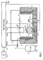
- cryogenic device allows a vitality-preserving freezing and thawing of a biological Sample 1, by the sample 1 is cooled or heated respectively during freezing and thawing according to a predetermined temporal temperature profile.
- the cryogenic device has a cryotube 2, which encloses a cooling space 3, wherein the cryogenic bath 2 has a wall 4 made of a thermally insulating material.
- the cooling of the cooling space 3 is effected by liquid nitrogen, which is contained in a coolant tank 5 shown only schematically here and is introduced into the cooling space 3 via a controllable coolant valve 6.
- the introduction of the liquid nitrogen into the cooling chamber 3 takes place here indirectly via a porous buffer material 7, with which the inside of the wall 4 of the cryotube 2 is covered, wherein on the inside of the buffer material 7, a grid 8 made of a good thermal conductivity material (eg copper) is arranged.
- the buffer material 7 prevents the supplied liquid nitrogen from collecting at the bottom of the cooling space 3 in the form of a so-called nitrogen lake. Instead, the supplied liquid nitrogen is discharged from the buffer material 7 uniformly through the grid 8 into the cooling space 3.
- cryotube 2 is covered by a removable protective bell 9, wherein the protective bell 9 is transparent, to allow a visual inspection of the cooling chamber 3.
- a sample container 10 which is raised by a lifting device 11 only shown schematically in the cooling chamber 3 in the vertical direction or, can be lowered, as will be described in detail.
- a temperature sensor 12 On the sample container 10 is a temperature sensor 12 which measures the temperature T IST1 in the sample container 10 and forwards it to a control device 13, wherein the control device 13 also controls the coolant valve 6 and thus adjusts the temperature in the cooling chamber 3.
- the sample container 10 has a cooling device 14, which is shown only schematically and the interior of the sample container 10 with a predetermined by the control device 13 cooling power P KÜHL cools, as will also be described in detail.
- the cooling device 14 may utilize the liquid nitrogen contained in the coolant tank 5 for cooling purposes, but other cooling techniques are applicable.
- sample container 10 is thermally insulated and has a likewise thermally insulated, closable lid 15, wherein the lid 15 is opened in order to introduce the sample 1 into the sample container 10 or to be able to remove it from the sample container 10.
- a further temperature sensor 16 is arranged at the bottom of the cooling space 3, which measures the temperature T IST2 at the bottom of the cooling space 3 and forwards it to the control device 13. The control device then regulates the temperature T IST2 to a predetermined desired value by controlling the coolant valve 6 accordingly.
- a removable transport container 17 which is thermally insulated and has a removable lid.
- the transport container 17 allows a transfer of the frozen sample 1 from the cooling chamber 3 in a cryotank, not shown here, without the sample 1 is heated during this transfer and thereby thermally damaged.
- the transport container 17 allows the transfer of the frozen sample 1 from a cryotank not shown here in the cooling chamber 3, so that the frozen sample 1 can then be thawed in the sample container 10, which will be described in detail.
- the control device 13 is finally connected to a conventional personal computer 18, wherein any temporal temperature curves for the freezing or thawing process can be programmed on the personal computer 18.
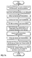
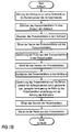
- FIG. 7A a freezing process of the cryo device described in Figure 1.
- control device 13 regulates the temperature T IST2 at the bottom of the cooling space 3 by a suitable control of the coolant valve 6 down to the predetermined target temperature of the freezing process.
- the empty sample container 10 is moved by the lifting device 11 in the cooling chamber 3 upwards in the dotted position shown, so that the mouth opening of the sample container 10 is located at an opening of the lid 5 above the cryotube 2.
- the lid 15 of the sample container 10 is then opened, whereupon the sample 1 is introduced into the sample container 10 and the lid 15 of the sample container is closed.
- the Sample 1 is hardly affected thermally because the temperatures in this area are close to the starting temperature of the freezing process.
- the control device 13 controls a predetermined temporal temperature profile by the cooling device 14 corresponding to the measured temperature of the temperature sensor T IST 14 controls the cooling device.
- the sample container 10 is then lowered into the cooling chamber 3 of the lifting device 11, wherein in the lower region of the cooling chamber 3, a temperature prevails, which corresponds substantially to the target temperature of the freezing process.
- a temperature prevails, which corresponds substantially to the target temperature of the freezing process.
- the sample 1 is then transferred after removal from the sample container 10 in the transport container 17, whereupon the transport container 17 can be removed with the frozen sample 1 therein from the cooling chamber 3 and stored for example in a cryogenic tank.
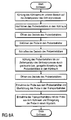
- FIG. 7B a thawing process of the cryogenic device according to FIG. 1 is described.
- the cooling space 3 is cooled to such an extent that the temperature T IST2 at the bottom of the cooling space 3 substantially corresponds to the starting temperature of the thawing process.
- the transport container 17 is removed with the frozen sample 1 therein from a cryotank not shown here and placed on the bottom of the cooling chamber 3.
- the lid 15 of the sample container 10 is opened, as well as the lid of the transport container 17 is opened.
- the sample 1 located in the transport container 17 is then removed from the transport container 17 and transferred to the sample container 10, whereupon the lid 15 of the sample container 10 is closed.
- the sample 1 is hardly affected thermally, since the temperatures at the bottom of the cooling chamber 3 are substantially equal to the temperature of the sample 1.
- the sample container 10 is then moved by the lifting device 11 in the cooling chamber 3 vertically upwards into the position shown in dotted.
- the interior of the sample container 10 is then heated according to a predetermined temporal temperature curve by the cooling power P KÜHL the cooling device 14 is reduced, the control device 13, the cooling power P KÜHL depending on the measured temperature T IST1 regulated to the desired temporal temperature profile in to reach the sample container 10 during thawing of the sample 1.
- the lid 15 of the sample container 10 is then opened, whereupon the thawed sample 1 is then removed from the sample container 10.
- the sample 1 is thermally hardly affected by the surrounding medium, since the temperatures in this area are relatively high.
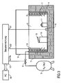
- FIG. 2 described alternative embodiment of a similar cryogenic device, which is largely with the above-described and in FIG. 1 illustrated embodiment of a cryogenics match. To avoid repetition, reference is therefore made largely to the above description, wherein the same reference numerals are used for corresponding components.
- cryogen has no separate, actively operating cooling device 14.
- the temperature of the sample container 10 takes place here by a vertical lowering or raising of the sample container 10 in the cooling chamber 3. Due to the vertical temperature stratification in the cooling chamber 3 then changes the temperature in the sample container 10, so that when thawing or freezing the Sample also predetermined temporal temperature curves can be set.
- the lowering or raising of the sample container 10 takes place here regulated by the control device 13 as a function of the measured temperature of the temperature sensor 12 T IST1 in the sample container 10th
- the sample container 10 is not thermally insulated in this case, so that the interior of the sample container 10, depending on its respective height within the cooling chamber 3, can assume the associated temperature.
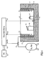
- FIG. 3 described alternative embodiment of a cryogenic device according to the invention, which partially coincides with the embodiments described above, so reference is made to avoid repetition of the above description, wherein the same reference numerals are used for corresponding components.
- a special feature of this exemplary embodiment consists firstly in that the sample container 10 is arranged fixedly in the cooling space 3 at the bottom of the cooling space 3, so that the lifting device 11 can be dispensed with.
- a heating device 19 is mounted on the inner wall of the cooling space 3 in the upper area, which heats the upper portion of the cooling space 3.
- the heater 19 is turned on by the controller 13 before a sample is introduced into the sample container 10 at the beginning of a freezing process. As a result, the upper portion of the cooling chamber 3 is heated, creating a thermal damage to the sample during insertion into the sample container 10 is prevented.
- the heater 19 is also turned on by the controller 13 before a thawed sample is removed from the sample container at the end of a thawing process. This also prevents the thawed sample from being thermally damaged when it is removed from the sample container 10.
- the heating device 19 is switched off when the sample is removed from the sample container 10 at the end of a freezing process and transferred to the transport container 17.
- the heater 19 is also switched off when the sample is transferred at the beginning of a thawing process from the transport container 17 into the sample container 10.
- This shutdown of the heater 19 in turn prevents thermal degradation of the frozen sample in the transfer between the sample container 10 and the transport container 17th
- FIG. 4 illustrated alternative embodiment is almost complete with that described above and in FIG. 3 illustrated embodiment, wherein only the protective bell 9 has been omitted.
- a special feature of this embodiment is that at the bottom of the cooling chamber 3, a plurality of stepped storage surfaces 20 are arranged, on each of which cryosubstrate can be stored temporarily. Due to the vertical temperature stratification in the cooling space 3, the individual storage surfaces 20 are each at different temperatures, so that a step-shaped temperature profile can be traversed in succession by a cryoprobe is successively deposited on the different storage surfaces 20.
- Another special feature of this embodiment is that a plurality of shelf-like storage surfaces 21 are arranged one above the other in the upper region of the cooling space 3, which also have different temperatures due to the vertical temperature stratification within the cooling space 3 and allow the storage of a sample.
- cryogenic device in this embodiment a lock 22, can be introduced via the sample into the cooling chamber 3 and removed from the cooling chamber 3.
- the protective bell 9 is provided with interventions 23, via which an operator can perform manipulations in the cold room 3.
- the cooling of the cooling space 3 takes place here through a nitrogen lake 24, which is generated at the bottom of the cooling space 3.
- the temperature control of the sample 1 in the form of a cryosubstrate within the sample container 10 takes place in a different manner, as will be described below.
- a vertically extending shaft 25 which consists of a good thermal conductivity material (for example copper) and generates an approximately constant vertical temperature gradient within the shaft 25 due to the good thermal conductivity, is arranged in the cooling space 3.
- the sample container 10 can be raised or lowered by a motor 26 via a rotatable spindle 27 in the shaft 25 in the vertical direction in order to temper the sample container 10 in accordance with the vertical temperature stratification in the cooling chamber 3.
- FIG. 5B It can also be seen that a plurality of temperature sensors 28-31, which measure a local vertical temperature gradient, are arranged above and below the sample container 10 at different heights, the temperature sensors 28-31 being connected to a control device which controls the motor 26 so that the sample container 10 is always located at the correct height within the cooling space 3, so that during the freezing or thawing of the sample 1, the desired temporal temperature profile is achieved.
- FIG. 5B shows that the slide-shaped sample container 10 contains a cryosubstrate 32 and a lid 33 and containers for the samples 1.
- FIG. 6 illustrated alternative embodiment, which is largely with the above described and in the Figures 5A and 5B
- a special feature of this embodiment is that several shafts 25 are arranged side by side in the cooling space 3, in each of which a sample container 10 can be raised or lowered in the vertical direction to set the desired temperature according to the vertical temperature stratification in the cooling chamber 3. This arrangement advantageously allows parallel freezing or thawing processes on multiple samples.
Abstract
Description
Die Erfindung betrifft eine Kryoeinrichtung zum Einfrieren und Auftauen einer Probe, insbesondere bei der Kryokonservierung einer biologischen Probe, sowie ein zugehöriges Betriebsverfahren gemäß dem Oberbegriff der nebengeordneten Ansprüche.The invention relates to a cryogenic device for freezing and thawing a sample, in particular in the cryopreservation of a biological sample, as well as an associated operating method according to the preamble of the independent claims.
Bei der bekannten Kryokonservierung werden biologische Proben vitalitätserhaltend eingefroren und später bei Bedarf wieder vitalitätserhaltend aufgetaut. Anwendungsbeispiele für eine solche Kryokonservierung sind die Einlagerung von Embryonen für die Stammzellforschung oder die Aufbewahrung von Spermien für eine spätere künstliche Befruchtung. Wichtig für die Vitalitätserhaltung bei der Kryokonservierung ist es, dass sowohl beim Einfrieren als auch beim Auftauen der biologischen Proben ein vorgegebener zeitlicher Temperaturverlauf eingehalten wird.In the known cryopreservation biological samples are frozen vitality and later thawed vitality when needed again. Examples of applications for such a cryopreservation include the storage of embryos for stem cell research or the storage of sperm for later artificial insemination. It is important for the preservation of vitality in cryopreservation that a predetermined temporal temperature profile is observed both during freezing and when thawing the biological samples.
Zur Kryokonservierung biologischer Proben werden deshalb sogenannte Einfrierautomaten eingesetzt, die als Kühlmittel meist flüssigen Stickstoff mit einem Siedepunkt von -196°C einsetzen und einen Kühlraum aufweisen, in dem die Temperatur durch eine Steuerung der Zufuhr des Kühlmittels eingestellt werden kann, um den gewünschten zeitlichen Temperaturverlauf beim Einfrieren bzw. Auftauen biologischer Proben zu erreichen.For cryopreservation of biological samples therefore so-called freezers are used, which use mostly liquid nitrogen with a boiling point of -196 ° C and have a cooling space in which the temperature can be adjusted by controlling the supply of the coolant to the desired temporal temperature profile when freezing or thawing biological samples to achieve.
Beim Einfrieren der biologischen Proben werden diese in den Kühlraum des Einfrierautomaten eingeführt und anschließend entsprechend dem vorgegebenen zeitlichen Temperaturverlauf von einer Starttemperatur eines Einfrierprozesses bis auf eine Zieltemperatur des Einfrierprozesses abgekühlt. Nach dem Erreichen der Zieltemperatur des Einfrierprozesses werden die eingefrorenen biologischen Proben dann aus dem Kühlraum des Einfrierautomaten entnommen und beispielsweise in einem Kryotank gelagert.When freezing the biological samples, these are introduced into the cold room of the automatic freezer and then cooled according to the predetermined temporal temperature profile from a start temperature of a freezing process to a target temperature of the freezing process. After reaching the target temperature of the freezing process, the frozen biological samples are then removed from the refrigerator of the freezer and stored for example in a cryogenic tank.
Beim Auftauen gefrorener biologischer Proben werden diese beispielsweise aus einem Kryotank entnommen und in den Kühlraum des Einfrierautomaten eingeführt. Anschließend wird die Temperatur der eingefrorenen biologischen Probe entsprechend einem vorgegebenen zeitlichen Temperaturverlauf von einer bestimmten Starttemperatur eines Auftauprozesses bis auf eine Zieltemperatur des Auftauprozesses angehoben. Nach dem Erreichen der Zieltemperatur des Auftauprozesses wird die aufgetaute Probe aus dem Kühlraum des Einfrierautomaten entnommen und weiter verwendet.When thawing frozen biological samples, for example, they are removed from a cryotank and introduced into the cold room of the automatic freezer. Subsequently, the temperature of the frozen biological sample is raised in accordance with a predetermined temporal temperature profile from a certain starting temperature of a thawing process up to a target temperature of the thawing process. After reaching the target temperature of the thawing process, the thawed sample is removed from the refrigerator of the automatic freezer and used again.
Ein Nachteil der vorstehend beschriebenen bekannten Einfrierautomaten besteht darin, dass die Probe beim Einführen in den Kühlraum und bei der Entnahme aus dem Kühlraum unerwünschten Temperatureinflüssen ausgesetzt ist, was die biologische Probe thermisch schädigen und das Ziel der Vitalitätserhaltung beeinträchtigen kann.A disadvantage of the above-described known automatic freezers is that the sample is exposed to undesirable temperature influences during introduction into the cold room and during removal from the cold room, which can thermally damage the biological sample and impair the goal of maintaining vitality.
Nachteilig an den vorstehend beschriebenen bekannten Einfrierautomaten ist weiterhin die unbefriedigende Genauigkeit bei der Einstellung des vorgegebenen zeitlichen Temperaturverlaufs beim Einfrieren bzw. Auftauen, was durch das relativ große Volumen des Kühlraums und die damit verbundenen regelungstechnischen Probleme verursacht wird.A disadvantage of the known freezers described above is still the unsatisfactory accuracy in setting the predetermined temporal temperature profile during freezing or thawing, which is caused by the relatively large volume of the refrigerator and the associated control problems.
Die Entgegenhaltungen
Ferner offenbart
Schließlich ist zum Stand der Technik noch auf die ferner liegende Druckschrift
Der Erfindung liegt deshalb die Aufgabe zugrunde, eine verbesserte Kryoeinrichtung zum Einfrieren und/oder Auftauen einer Probe und ein entsprechendes Betriebsverfahren zu schaffen.The invention is therefore based on the object to provide an improved cryogen for freezing and / or thawing a sample and a corresponding operating method.
Diese Aufgabe wird durch eine Kryoeinrichtung und ein entsprechendes Betriebsverfahren gemäß den Ansprüchen 1 und 17 gelöst.This object is achieved by a cryogenic device and a corresponding operating method according to
Die Erfindung umfasst die allgemeine technische Lehre, in dem relativ großen Kühlraum einer Kryoeinrichtung (z.B. eines Einfrierautomaten) einen Probenbehälter anzuordnen, in dem die Probe eingefroren und/oder aufgetaut wird, wobei der Probenbehälter getrennt von dem Kühlraum temperierbar ist. Dies bedeutet, dass in dem Probenbehälter und in dem Kühlraum unterschiedliche Temperaturen eingestellt werden können.The invention comprises the general technical teaching of arranging in the relatively large cooling space of a cryogen (for example a freezer) a sample container in which the sample is frozen and / or thawed, the sample container being temperature-controlled separately from the cooling space. This means that different temperatures can be set in the sample container and in the cold room.
Zum einen bietet die getrennte Einstellbarkeit der Temperatur in dem Probenbehälter den Vorteil, dass der für die Vitalitätserhaltung der biologischen Probe wichtige zeitliche Temperaturverlauf beim Einfrieren bzw. Auftauen nur für das kleinere Volumen innerhalb des Probenbehälters eingestellt werden muss, was regelungstechnisch wesentlich genauer möglich ist als die exakte Temperierung des gesamten Kühlraums des Einfrierautomaten.On the one hand, the separate adjustability of the temperature in the sample container offers the advantage that the important for the vitality preservation of the biological sample temporal temperature course during freezing or thawing must be set only for the smaller volume within the sample container, which is technically much more possible than the control technology exact temperature control of the entire refrigerator of the automatic freezer.
Zum anderen bietet die getrennte Einstellbarkeit der Temperatur in dem Probenbehälter unabhängig von dem sonstigen Kühlraum den Vorteil, dass beim Einführen und bei der Entnahme der Probe die vorstehend beschriebenen störenden und vitalitätsschädigenden Temperatureinwirkungen vermeidbar sind, die durch Abweichungen von der vorgegebenen Start- bzw. Zieltemperatur resultieren.On the other hand, the separate adjustability of the temperature in the sample container independently of the other refrigerator offers the advantage that the above-described disturbing and vitalitätsschädigenden temperature effects can be avoided during insertion and removal of the sample, resulting from deviations from the predetermined start or target temperature ,
Ferner ist zu erwähnen, dass in dem Kühlraum ein entnehmbarer, thermisch isolierter Transportbehälter angeordnet ist, um die Probe nach dem Einfrieren aus dem Kühlraum zu entnehmen oder zum Auftauen in den Kühlraum einzuführen. Zu Beginn eines Auftauprozesses wird die Probe dann aus dem Transportbehälter entnommen und in den Probenbehälter überführt, wo die Probe dann aufgetaut wird. In gleicher Weise wird die Probe am Ende eines Einfrierprozesses aus dem Probenbehälter entnommen und in den Transportbehälter überführt, der dann aus dem Kühlraum entnommen und beispielsweise in einem Kryotank eingelagert werden kannIt should also be mentioned that a removable, thermally insulated transport container is arranged in the cold room to remove the sample from the refrigerator after freezing or to introduce it into the cold room for thawing. At the beginning of a thawing process, the sample is then removed from the transport container and transferred to the sample container, where the sample is thawed. In the same way, the sample is removed from the sample container at the end of a freezing process and transferred to the transport container, which can then be removed from the cold room and stored, for example, in a cryotank
Die erfindungsgemäße Kryoeinrichtung weist vorzugsweise eine Hebeeinrichtung auf, durch die der Probenbehälter in dem Kühlraum gesteuert oder geregelt abgesenkt und/oder angehoben werden kann.The cryogenic device according to the invention preferably has a lifting device, by means of which the sample container in the cooling space can be controlled or lowered lowered and / or raised.
Zum einen ermöglicht diese vertikale Bewegung des Probenbehälters in dem Kühlraum eine Berücksichtigung der vertikalen Temperaturschichtung in dem Kühlraum. So nimmt die Temperatur in dem Kühlraum von oben nach unten ab, so dass der Probenbehälter am Ende eines Einfrierprozesses vorzugsweise abgesenkt ist, damit die eingefrorene Probe ohne störende Temperatureinwirkungen des umgebenden Mediums innerhalb des Kühlraums entnommen werden kann. Am Ende eines Auftauprozesses ist der Probenbehälter dagegen vorzugsweise in einer angehobenen Position, damit die aufgetaute Probe ohne störende Temperatureinwirkungen des am Boden des Kühlraums befindlichen, extrem kalten Mediums zu vermeiden.On the one hand, this vertical movement of the sample container in the cold room enables consideration of the vertical temperature stratification in the cold room. Thus, the temperature in the cold room decreases from top to bottom, so that the sample container is preferably lowered at the end of a freezing process, so that the frozen sample can be removed without disturbing temperature effects of the surrounding medium within the cold room. On the other hand, at the end of a thawing process the sample container is preferably in a raised position in order to avoid the thawed sample without disturbing temperature effects of the extremely cold medium located at the bottom of the cold room.
Zum anderen ermöglicht die vertikale Bewegung des Probenbehälters durch die Hebeeinrichtung in einer Variante der Erfindung eine Temperierung des Probenbehälters, indem der Probenbehälter entsprechend der gewünschten Temperatur innerhalb der vertikalen Temperaturschichtung in dem Kühlraum angehoben oder abgesenkt wird. Bei dieser Variante der Erfindung kann der Probenbehälter also auch ohne eine separate Kühleinrichtung getrennt von dem Kühlraum temperiert werden, indem der Probenbehälter entsprechend angehoben bzw. abgesenkt wird.On the other hand, the vertical movement of the sample container by the lifting device in a variant of the invention allows a tempering of the sample container by the sample container is raised or lowered according to the desired temperature within the vertical temperature stratification in the refrigerator. In this variant of the invention, the sample container can thus be tempered separately from the cooling space without a separate cooling device by the sample container is raised or lowered accordingly.
Hierbei ist es vorteilhaft, wenn der Probenbehälter einen Temperatursensor aufweist, der die Temperatur in dem Probenbehälter oder auf Höhe des Probenbehälters oder darunter bzw. darüber misst, damit die vertikale Bewegung des Probenbehälters in dem Kühlraum temperaturabhängig geregelt werden kann.It is advantageous if the sample container has a temperature sensor which measures the temperature in the sample container or at the level of the sample container or below or above, so that the vertical movement of the sample container can be temperature-dependent controlled in the refrigerator.
Besonders vorteilhaft ist es hierbei, wenn an dem Probenbehälter mehrere Temperatursensoren in unterschiedlichem vertikalen Abstand zu dem Probenbehälter angebracht sind, was die Ermittlung eines lokalen vertikalen Temperaturgradienten ermöglicht. Die Regelung der Aufwärts- bzw. Abwärtsbewegung des Probenbehälters kann dann sehr feinfühlig auf lokale Temperaturschwankungen in dem Kühlraum reagieren.It is particularly advantageous here if a plurality of temperature sensors are mounted on the sample container at different vertical distances from the sample container, which makes it possible to determine a local vertical temperature gradient. The regulation of the upward or downward movement of the sample container can then react very sensitively to local temperature fluctuations in the cooling space.
Es besteht jedoch alternativ auch die Möglichkeit, dass der Probenbehälter ortsfest in dem Kühlraum angeordnet ist, wobei sich der Probenbehälter vorzugsweise am Boden des Kühlraums befindet. Die Temperaturänderung an der Öffnung des Probenbehälters wird hierbei nicht durch eine Anhebung bzw. Absenkung des Probenbehälters erreicht, sondern kann beispielsweise durch eine Heizung realisiert werden, die den Kühlraum beheizt, wobei die Heizeinrichtung vorzugsweise nur einen oberen Teilbereich des Kühlraums beheizt. Die Heizeinrichtung wird dann vorzugsweise angeschaltet, wenn am Beginn eines Einfrierprozesses eine Probe in den Probenbehälter eingeführt werden soll oder wenn die Probe am Ende eines Auftauprozesses aus dem Probenbehälter entnommen wird. Die Beheizung des oberen Bereichs des Kühlraums verhindert dann vorteilhafterweise eine störende thermische Beeinträchtigung der Probe beim Einführen bzw. bei der Entnahme der Probe. Die Heizeinrichtung wird dagegen vorzugsweise abgeschaltet, wenn die Probe am Ende eines Einfrierprozesses aus dem Probenbehälter entnommen wird oder wenn die Probe zu Beginn eines Auftauprozesses in den Probenbehälter eingeführt wird. Die Abschaltung der Heizung verhindert dann ebenfalls, dass die gefrorene Probe beim Einführen bzw. bei der Entnahme thermisch beschädigt wird.However, there is also the alternative possibility that the sample container is arranged stationary in the cold room, wherein the sample container is preferably located at the bottom of the refrigerator. The temperature change at the opening of the sample container is not achieved by an increase or decrease of the sample container, but can be realized for example by a heater that heats the refrigerator, the heater preferably only heats an upper portion of the refrigerator. The heater is then preferably turned on when a sample is to be introduced into the sample container at the beginning of a freezing process or when the sample is removed from the sample container at the end of a thawing process. The heating of the upper region of the cooling space then advantageously prevents a disturbing thermal impairment of the sample during insertion or during the removal of the sample. On the other hand, the heater is preferably turned off when the sample is removed from the sample container at the end of a freezing process, or when the sample is introduced into the sample container at the beginning of a thawing process. The shutdown of the heater then also prevents the frozen sample is thermally damaged during insertion or removal.
Vorzugsweise besteht in dem Kühlraum eine vertikale Temperaturschichtung mit einer unteren Kaltschicht und einer oberen Warmschicht. Dies ist vorteilhaft, weil der Probenbehälter dabei für die Entnahme bzw. Einführung der Probe in die Temperaturschicht angehoben bzw. abgesenkt werden kann, die der aktuellen Probentemperatur am nächsten kommt und damit eine thermische Beeinträchtigung der Probe vermeidet.Preferably, in the cold room there is a vertical temperature stratification with a lower cold layer and an upper one Warm layer. This is advantageous because the sample container can be raised or lowered for the removal or introduction of the sample into the temperature layer, which comes closest to the current sample temperature and thus avoids a thermal impairment of the sample.
Bei einer derartigen vertikalen Temperaturschichtung innerhalb des Kühlraums weist die Warmschicht vorzugsweise eine Temperatur auf, die im Wesentlichen einer vorgegebenen Starttemperatur eines Einfrierprozesses oder einer vorgegebenen Zieltemperatur eines Auftauprozesses entspricht, während die Kaltschicht eine Temperatur aufweist, die im Wesentlichen einer vorgegebenen Zieltemperatur des Einfrierprozesses oder einer vorgegebenen Starttemperatur des Auftauprozesses entspricht. Dies ist vorteilhaft, weil die beiden Temperaturschichten in dem Kühlraum dann stets die richtige Temperatur aufweisen, um bei der Entnahme der Probe bzw. beim Einführen in den Probenbehälter eine thermische Beeinträchtigung der Probe zu vermeiden.In such a vertical temperature stratification within the cooling space, the heat layer preferably has a temperature that substantially corresponds to a predetermined start temperature of a freezing process or a predetermined target temperature of a thawing process, while the cold layer has a temperature substantially a predetermined target temperature of the freezing process or a predetermined Start temperature of the thawing process corresponds. This is advantageous because the two temperature layers in the cooling space then always have the correct temperature in order to avoid a thermal impairment of the sample when the sample is removed or when it is introduced into the sample container.
In einem bevorzugten Ausführungsbeispiel der Erfindung ist der Probenbehälter thermisch isoliert und weist einen Deckel auf, der zur Entnahme der Probe und zum Einführen der Probe geöffnet werden kann. Die thermische Isolation des Probenbehälters ist wichtig, wenn die Temperierung des Probenbehälters aktiv durch eine Kühlung und/oder Heizung erfolgt, da die Temperatureinstellung in dem Probenbehälter dann von der Umgebungstemperatur innerhalb des Kühlraums nur minimal beeinflusst wird.In a preferred embodiment of the invention, the sample container is thermally insulated and has a lid which can be opened to remove the sample and to introduce the sample. The thermal insulation of the sample container is important if the temperature of the sample container is actively carried out by cooling and / or heating, since the temperature setting in the sample container is then only minimally affected by the ambient temperature within the cold room.
Es ist jedoch alternativ auch möglich, dass der Probenbehälter gegenüber dem Kühlraum thermisch nicht isoliert ist. Dies ist insbesondere dann sinnvoll, wenn die Temperierung des Probenbehälters nicht aktiv durch eine Heiz- bzw. Kühleinrichtung erfolgt, sondern durch eine vertikale Bewegung des Probenbehälters innerhalb der vertikalen Temperaturschichtung des Kühlraums, wie vorstehend bereits erläutert wurde.However, it is alternatively also possible for the sample container to be thermally uninsulated relative to the cooling space. This is particularly useful when the temperature of the sample container is not active by a heating or cooling device takes place, but by a vertical movement of the sample container within the vertical temperature stratification of the refrigerator, as already explained above.
In einem bevorzugten Ausführungsbeispiel der Erfindung ist in dem Kühlraum mindestens ein im Wesentlichen senkrecht verlaufender Schacht mit einer Wandung aus einem wärmeleitfähigen Material angeordnet, wobei der Probenbehälter in dem Schacht vertikal beweglich ist. Die gute Wärmeleitfähigkeit der Schachtwandung führt hierbei vorteilhaft zu einem annähernd konstanten vertikalen Temperaturgradienten in dem Schacht, so dass jeder Höhe in dem Schacht eine bestimmte Temperatur zugeordnet werden kann. Dies ermöglicht vorteilhaft den Verzicht auf Temperatursensoren an dem Probenbehälter.In a preferred embodiment of the invention, at least one substantially vertically extending shaft with a wall made of a thermally conductive material is arranged in the cooling space, wherein the sample container is vertically movable in the shaft. The good thermal conductivity of the shaft wall advantageously leads to an approximately constant vertical temperature gradient in the shaft, so that each height in the shaft can be assigned a specific temperature. This advantageously makes it possible to dispense with temperature sensors on the sample container.
Der Kühlraum selbst ist bei der erfindungsgemäßen Kryoeinrichtung vorzugsweise wannenförmig ausgebildet und an seiner Oberseite durch eine abnehmbare Schutzhaube abgedeckt, die vorzugsweise mindestens teilweise durchsichtig ist, um eine Sichtkontrolle zu ermöglichen.The refrigerator itself is preferably trough-shaped in the cryogenic device according to the invention and covered on its upper side by a removable protective cover, which is preferably at least partially transparent, in order to allow a visual inspection.
Es besteht jedoch alternativ auch die Möglichkeit eines Verzichts auf eine Schutzhaube, so dass der Kühlraum nach oben hin offen ist.However, there is also the alternative possibility of waiving a protective hood, so that the refrigerator is open at the top.
Ferner ist zu erwähnen, dass in dem Kühlraum mehrere Ablageflächen in unterschiedlichen Höhen angeordnet sein können, die unterschiedlichen Temperaturen entsprechend der vertikalen Temperaturschichtung in dem Kühlraum entsprechen.It should also be mentioned that in the cooling space a plurality of storage surfaces can be arranged at different heights, which correspond to different temperatures corresponding to the vertical temperature stratification in the cooling space.
Schließlich ist noch zu erwähnen, dass die Erfindung nicht nur die vorstehend beschriebene erfindungsgemäße Kryoeinrichtung umfasst, sondern auch ein entsprechendes Betriebsverfahren, das sich aus der vorstehenden Beschreibung ergibt.Finally, it should be mentioned that the invention comprises not only the above-described cryogenic device according to the invention, but also a corresponding operating method, which results from the above description.
Andere vorteilhafte Weiterbildungen der Erfindung sind in den Unteransprüchen gekennzeichnet oder werden nachstehend zusammen mit der Beschreibung der bevorzugten Ausführungsbeispiele der Erfindung anhand der Figuren näher erläutert. Es zeigen:
- Figur 1
- eine schematisierte Querschnittsansicht einer erfindungsgemäßen Kryoeinrichtung zum vitalitätserhaltenden Einfrieren und Auftauen einer biologischen Probe,
Figur 2- eine schematisierte Querschnittsdarstellung eines abgewandelten Ausführungsbeispiels einer Kryoeinrichtung gemäß
Figur 1 , Figur 3- eine schematisierte Querschnittsansicht eines alternativen Ausführungsbeispiels einer erfindungsgemäßen Kryoeinrichtung mit einer zusätzlichen Heizeinrichtung,
Figur 4- eine schematisierte Querschnittsansicht eines vereinfachten Ausführungsbeispiels einer derartigen Kryoeinrichtung, die im Gegensatz zu den anderen Kryoeinrichtungen keine Schutzhaube aufweist,
- Figur 5A
- eine vereinfachte Querschnittsansicht eines weiteren Ausführungsbeispiels einer erfindungsgemäßen Kryoeinrichtung,
- Figur 5B
- eine Querschnittsansicht einer Hebeeinrichtung der Kryoeinrichtung aus
Fig. 5A zur Anhebung bzw. Absenkung der Probe, Figur 6- eine vereinfachte Querschnittsansicht eines weiteren Ausführungsbeispiels einer erfindungsgemäßen Kryoeinrichtung mit mehreren Hebeeinrichtungen zum gleichzeitigen Einfrieren bzw. Auftauen mehrerer Proben unabhängig voneinander,
- Figur 7A
- einen Einfrierprozess bei dem Ausführungsbeispiel gemäß
Figur 1 in Form eines Flussdiagramms, - Figur 7B
- einen Auftauprozess bei dem Ausführungsbeispiel gemäß
Figur 1 in Form eines Flussdiagramms, - Figur 8A
- einen Einfrierprozess bei dem Ausführungsbeispiel
gemäß den Figuren 2 und5A ,5B in Form eines Flussdiagramms sowie - Figur 8B
- einen Auftauprozess bei den
Ausführungsbeispielen gemäß Figur 2 bzw. 5A, 5B.
- FIG. 1
- 1 is a schematic cross-sectional view of a cryogenic device according to the invention for vitality-preserving freezing and thawing of a biological sample;
- FIG. 2
- a schematic cross-sectional view of a modified embodiment of a cryo according to
FIG. 1 . - FIG. 3
- 4 is a schematic cross-sectional view of an alternative embodiment of a cryogenic device according to the invention with an additional heating device,
- FIG. 4
- FIG. 2 is a schematic cross-sectional view of a simplified embodiment of such a cryogenic device, which has no protective cap in contrast to the other cryogenic devices, FIG.
- FIG. 5A
- a simplified cross-sectional view of another embodiment of a cryogenic device according to the invention,
- FIG. 5B
- a cross-sectional view of a lifting device of the cryo
Fig. 5A for raising or lowering the sample, - FIG. 6
- 2 shows a simplified cross-sectional view of a further embodiment of a cryogenic device according to the invention having a plurality of lifting devices for simultaneously freezing or thawing a plurality of samples independently of one another,
- FIG. 7A
- a freezing process in the embodiment according to
FIG. 1 in the form of a flowchart, - FIG. 7B
- a thawing process in the embodiment according to
FIG. 1 in the form of a flowchart, - Figure 8A
- a freezing process in the embodiment according to the
Figures 2 and5A .5B in the form of a flowchart as well - FIG. 8B
- a thawing process in the embodiments according to
FIG. 2 or 5A, 5B.
Die in
Hierzu weist die Kryoeinrichtung eine Kryowanne 2 auf, die einen Kühlraum 3 einschließt, wobei die Kryowanne 2 eine Wandung 4 aus einem thermisch isolierenden Material aufweist.For this purpose, the cryogenic device has a
Die Kühlung des Kühlraums 3 erfolgt durch flüssigen Stickstoff, der in einem hier nur schematisch dargestellten Kühlmittelbehälter 5 enthalten ist und über ein steuerbares Kühlmittelventil 6 in den Kühlraum 3 eingeleitet wird.The cooling of the
Die Einleitung des flüssigen Stickstoffs in den Kühlraum 3 erfolgt hierbei indirekt über ein poröses Puffermaterial 7, mit dem die Innenseite der Wandung 4 der Kryowanne 2 verkleidet ist, wobei an der Innenseite des Puffermaterials 7 ein Gitter 8 aus einem gut wärmeleitfähigen Material (z.B. Kupfer) angeordnet ist. Das Puffermaterial 7 verhindert, dass sich der zugeführte flüssige Stickstoff am Boden des Kühlraums 3 in Form eine sogenannten Stickstoffsees sammelt. Stattdessen wird der zugeführte flüssige Stickstoff von dem Puffermaterial 7 gleichmäßig durch das Gitter 8 hindurch in den Kühlraum 3 abgegeben.The introduction of the liquid nitrogen into the
An ihrer Oberseite ist die Kryowanne 2 durch eine abnehmbare Schutzglocke 9 abgedeckt, wobei die Schutzglocke 9 durchsichtig ist, um eine Sichtkontrolle des Kühlraums 3 zu ermöglichen.At its top, the
In dem Kühlraum 3 befindet sich ein Probenbehälter 10, der von einer hier nur schematisch dargestellten Hebeeinrichtung 11 in dem Kühlraum 3 in vertikaler Richtung angehoben bzw, abgesenkt werden kann, wie noch detailliert beschrieben wird.In the
An dem Probenbehälter 10 befindet sich ein Temperatursensor 12, der die Temperatur TIST1 in dem Probenbehälter 10 misst und an eine Steuereinrichtung 13 weiterleitet, wobei die Steuereinrichtung 13 auch das Kühlmittelventil 6 ansteuert und damit die Temperatur in dem Kühlraum 3 einstellt.On the
Weiterhin weist der Probenbehälter 10 eine Kühleinrichtung 14 auf, die nur schematisch dargestellt ist und den Innenraum des Probenbehälters 10 mit einer durch die Steuereinrichtung 13 vorgegebenen Kühlleistung PKÜHL kühlt, wie ebenfalls noch detailliert beschrieben wird. Die Kühleinrichtung 14 kann beispielsweise den in dem Kühlmittelbehälter 5 enthaltenen flüssigen Stickstoff zu Kühlzwecken nutzen, jedoch sind auch andere Kühltechniken anwendbar.Furthermore, the
Weiterhin ist zu erwähnen, dass der Probenbehälter 10 thermisch isoliert ist und einen ebenfalls thermisch isolierten, verschließbaren Deckel 15 aufweist, wobei der Deckel 15 geöffnet wird, um die Probe 1 in den Probenbehälter 10 einführen bzw. aus dem Probenbehälter 10 entnehmen zu können.It should also be mentioned that the
Ferner ist am Boden des Kühlraums 3 ein weiterer Temperatursensor 16 angeordnet, der die Temperatur TIST2 am Boden des Kühlraums 3 misst und an die Steuereinrichtung 13 weiterleitet. Die Steuereinrichtung regelt dann die Temperatur TIST2 auf einen vorgegebenen Sollwert ein, indem das Kühlmittelventil 6 entsprechend angesteuert wird.Furthermore, a
Darüber hinaus befindet sich am Boden des Kühlraums 3 ein entnehmbarer Transportbehälter 17, der thermisch isoliert ist und einen abnehmbaren Deckel aufweist. Der Transportbehälter 17 ermöglicht eine Überführung der tiefgefrorenen Probe 1 aus dem Kühlraum 3 in einem hier nicht dargestellten Kryotank, ohne dass die Probe 1 während dieser Überführung erwärmt und dadurch thermisch beschädigt wird. Darüber hinaus ermöglicht der Transportbehälter 17 die Überführung der tiefgefrorenen Probe 1 aus einem hier nicht dargestellten Kryotank in den Kühlraum 3, damit die gefrorene Probe 1 anschließend in dem Probenbehälter 10 aufgetaut werden kann, was noch detailliert beschrieben wird.In addition, located at the bottom of the
Die Steuereinrichtung 13 ist schließlich mit einem herkömmlichen Personal-Computer 18 verbunden, wobei an dem Personal-Computer 18 beliebige zeitliche Temperaturverläufe für den Einfrier- bzw. Auftauprozess programmiert werden können.The
Im Folgenden wird nun unter Bezugnahme auf das Flussdiagramm in
Dabei regelt die Steuereinrichtung 13 die Temperatur TIST2 am Boden des Kühlraums 3 durch eine geeignete Ansteuerung des Kühlmittelventils 6 auf die vorgegebene Zieltemperatur des Einfrierprozesses herunter.In this case, the
Weiterhin wird der leere Probenbehälter 10 von der Hebeeinrichtung 11 in dem Kühlraum 3 nach oben in die punktiert dargestellte Position gefahren, so dass die Mündungsöffnung des Probenbehälters 10 bei einer Öffnung des Deckels 5 oberhalb der Kryowanne 2 liegt.Furthermore, the
Der Deckel 15 des Probenbehälters 10 wird dann geöffnet, woraufhin die Probe 1 in den Probenbehälter 10 eingeführt und der Deckel 15 des Probenbehälters geschlossen wird. Bei diesem Einführen der Probe 1 in den Probenbehälter 10 wird die Probe 1 thermisch kaum beeinträchtigt, da die Temperaturen in diesem Gebiet nahe der Starttemperatur des Einfrierprozesses liegen.The
Nach dem Verschließen des Probenbehälters 10 wird dessen Innenraum dann von der Kühleinrichtung 14 gekühlt, wobei die Steuereinrichtung 13 einen vorgegebenen zeitlichen Temperaturverlauf regelt, indem die Kühleinrichtung 14 entsprechend der von dem Temperatursensor 12 gemessenen Temperatur TIST die Kühleinrichtung 14 ansteuert.After closing the
Nach dem Abschluss des Einfrierprozesses wird der Probenbehälter 10 dann in den Kühlraum 3 von der Hebeeinrichtung 11 heruntergefahren, wobei im unteren Bereich des Kühlraums 3 eine Temperatur herrscht, die im Wesentlichen der Zieltemperatur des Einfrierprozesses entspricht. Beim anschließenden Öffnen des Deckels 15 und der Entnahme der Probe 1 aus dem Probenbehälter 10 wird die gefrorene Probe 1 dann thermisch kaum beeinträchtigt, da das umgebende Medium in dem Kühlraum 3 nahezu die gleiche Temperatur hat.After completion of the freezing process, the
Die Probe 1 wird dann nach der Entnahme aus dem Probenbehälter 10 in den Transportbehälter 17 überführt, woraufhin der Transportbehälter 17 mit der darin befindlichen tiefgefrorenen Probe 1 aus dem Kühlraum 3 entnommen und beispielsweise in einem Kryotank eingelagert werden kann.The sample 1 is then transferred after removal from the
Im Folgenden wird nun unter Bezugnahme auf das Flussdiagramm in
Hierbei wird der Kühlraum 3 so weit gekühlt, dass die Temperatur TIST2 am Boden des Kühlraums 3 im Wesentlichen der Starttemperatur des Auftauprozesses entspricht.In this case, the
Anschließend wird dann der Transportbehälter 17 mit der darin befindlichen tiefgefrorenen Probe 1 aus einem hier nicht dargestellten Kryotank entnommen und auf den Boden des Kühlraums 3 gestellt.Subsequently, the
Daraufhin wird dann der Deckel 15 des Probenbehälter 10 geöffnet, wie auch der Deckel des Transportbehälters 17 geöffnet wird.Then, the
Die in dem Transportbehälter 17 befindliche Probe 1 wird dann aus dem Transportbehälter 17 entnommen und in den Probenbehälter 10 überführt, woraufhin dann der Deckel 15 des Probenbehälters 10 geschlossen wird. Bei der Überführung der Probe 1 aus dem Transportbehälter 17 in den Probenbehälter 10 wird die Probe 1 thermisch kaum beeinträchtigt, da die Temperaturen am Boden des Kühlraums 3 im Wesentlichen gleich der Temperatur der Probe 1 sind.The sample 1 located in the
Nach dem Verschließen des Probenbehälters 10 wird der Probenbehälter 10 dann von der Hebeeinrichtung 11 in dem Kühlraum 3 vertikal nach oben in die punktiert dargestellte Position gefahren.After closing the
Anschließend wird der Innenraum des Probenbehälters 10 dann entsprechend einem vorgegebenen zeitlichen Temperaturverlauf erwärmt, indem die Kühlleistung PKÜHL der Kühleinrichtung 14 verringert wird, wobei die Steuereinrichtung 13 die Kühlleistung PKÜHL in Abhängigkeit von der gemessenen Temperatur TIST1 regelt, um den gewünschten zeitlichen Temperaturverlauf in dem Probenbehälter 10 beim Auftauen der Probe 1 zu erreichen.Subsequently, the interior of the
Nach dem Ende des Auftauprozesses wird der Deckel 15 des Probenbehälters 10 dann geöffnet, woraufhin die aufgetaute Probe 1 dann aus dem Probenbehälter 10 entnommen wird.After the end of the thawing process, the
Auch bei dieser Entnahme der aufgetauten Probe 1 aus dem Probenbehälter 10 wird die Probe 1 von dem umgebenden Medium thermisch kaum beeinträchtigt, da die Temperaturen in diesem Gebiet relativ hoch sind.Even with this removal of the thawed sample 1 from the
Im Folgenden wird nun das in
Eine Besonderheit dieses Ausführungsbeispiels besteht darin, dass die Kryoeinrichtung keine separate, aktiv arbeitende Kühleinrichtung 14 aufweist.A special feature of this embodiment is that the cryogen has no separate, actively operating cooling
Stattdessen erfolgt die Temperierung des Probenbehälters 10 hierbei durch eine vertikale Absenkung bzw. Anhebung des Probenbehälters 10 in dem Kühlraum 3. Aufgrund der vertikalen Temperaturschichtung in dem Kühlraum 3 ändert sich dann auch die Temperatur in dem Probenbehälter 10, so dass beim Auftauen bzw. Einfrieren der Probe ebenfalls vorgegebene zeitliche Temperaturverläufe eingestellt werden können. Das Absenken bzw. Anheben des Probenbehälters 10 erfolgt hierbei geregelt von der Steuereinrichtung 13 in Abhängigkeit von der von dem Temperatursensor 12 gemessenen Temperatur TIST1 in dem Probenbehälter 10.Instead, the temperature of the
Im Gegensatz zu dem Ausführungsbeispiel gemäß
Der Ablauf des Einfrierprozesses ergibt sich hierbei aus dem Flussdiagramm gemäß
Nachfolgend wird nun das in
Eine Besonderheit dieses Ausführungsbeispiels besteht zunächst darin, dass der Probenbehälter 10 in dem Kühlraum 3 ortsfest am Boden des Kühlraums 3 angeordnet ist, so dass auf die Hebeeinrichtung 11 verzichtet werden kann.A special feature of this exemplary embodiment consists firstly in that the
Eine weitere Besonderheit dieses Ausführungsbeispiels besteht darin, dass an der Innenwand des Kühlraums 3 im oberen Bereich eine Heizeinrichtung 19 angebracht ist, die den oberen Teilbereich des Kühlraums 3 beheizt.Another special feature of this exemplary embodiment is that a
Die Heizeinrichtung 19 wird von der Steuereinrichtung 13 angeschaltet, bevor eine Probe zu Beginn eines Einfrierprozesses in den Probenbehälter 10 eingeführt wird. Dadurch wird der obere Teilbereich des Kühlraums 3 beheizt, wodurch eine thermische Beschädigung der Probe beim Einführen in den Probenbehälter 10 verhindert wird.The
Darüber hinaus wird die Heizeinrichtung 19 von der Steuereinrichtung 13 auch angeschaltet, bevor eine aufgetaute Probe am Ende eines Auftauprozesses aus dem Probenbehälter entnommen wird. Auch dadurch wird verhindert, dass die aufgetaute Probe bei der Entnahme aus dem Probenbehälter 10 thermisch beschädigt wird.In addition, the
Die Heizeinrichtung 19 wird dagegen abgeschaltet, wenn die Probe am Ende eines Einfrierprozesses aus dem Probenbehälter 10 entnommen und in den Transportbehälter 17 überführt wird.On the other hand, the
Darüber hinaus wird die Heizeinrichtung 19 auch abgeschaltet, wenn die Probe zu Beginn eines Auftauprozesses aus dem Transportbehälter 17 in den Probenbehälter 10 überführt wird.In addition, the
Diese Abschaltung der Heizeinrichtung 19 verhindert wiederum eine thermische Beeinträchtigung der tiefgekühlten Probe bei der Überführung zwischen dem Probenbehälter 10 und dem Transportbehälter 17.This shutdown of the
Das in
Im Folgenden wird nun das in den
Eine Besonderheit dieses Ausführungsbeispiels besteht darin, dass am Boden des Kühlraums 3 mehrere stufenförmige Ablageflächen 20 angeordnet sind, auf denen jeweils Kryosubstrate vorübergehend abgelegt werden können. Aufgrund der vertikalen Temperaturschichtung in dem Kühlraum 3 liegen die einzelnen Ablageflächen 20 jeweils auf unterschiedlichen Temperaturen, so dass ein stufenförmiges Temperaturprofil zeitlich aufeinanderfolgend durchfahren werden kann, indem eine Kryoprobe nacheinander auf den verschiedenen Ablageflächen 20 abgelegt wird.A special feature of this embodiment is that at the bottom of the
Eine weitere Besonderheit dieses Ausführungsbeispiels besteht darin, dass im oberen Bereich des Kühlraums 3 übereinander mehrere regalartige Ablageflächen 21 angeordnet sind, die ebenfalls aufgrund der vertikalen Temperaturschichtung innerhalb des Kühlraums 3 unterschiedliche Temperaturen aufweisen und die Ablage einer Probe ermöglichen.Another special feature of this embodiment is that a plurality of shelf-like storage surfaces 21 are arranged one above the other in the upper region of the
Darüber hinaus weist die Kryoeinrichtung in diesem Ausführungsbeispiel eine Schleuse 22 auf, über die Proben in den Kühlraum 3 eingebracht und aus dem Kühlraum 3 entnommen werden können.In addition, the cryogenic device in this embodiment, a
Weiterhin ist die Schutzglocke 9 mit Eingriffen 23 versehen, über die eine Bedienungsperson Manipulationen in dem Kühlraum 3 vornehmen kann.Furthermore, the
Die Kühlung des Kühlraums 3 erfolgt hierbei durch einen Stickstoffsee 24, der am Boden des Kühlraums 3 erzeugt wird.The cooling of the
Die Temperierung der Probe 1 in Form eines Kryosubstrats innerhalb des Probenbehälters 10 erfolgt hierbei jedoch in anderer Weise, wie nachfolgend beschrieben wird.However, the temperature control of the sample 1 in the form of a cryosubstrate within the
Hierzu ist in dem Kühlraum 3 ein vertikal verlaufender Schacht 25 angeordnet, der aus einem gut wärmeleitfähigen Material (z.B. Kupfer) besteht und innerhalb des Schachts 25 aufgrund der guten Wärmeleitfähigkeit einen annähernd konstanten vertikalen Temperaturgradienten erzeugt.For this purpose, a vertically extending
Der Probenbehälter 10 kann von einem Motor 26 über eine drehbare Spindel 27 in dem Schacht 25 in vertikaler Richtung angehoben oder abgesenkt werden, um den Probenbehälter 10 entsprechend der vertikalen Temperaturschichtung in dem Kühlraum 3 zu temperieren.The
Aus
Weiterhin zeigt die vergrößerte Querschnittsansicht in Figur 5B, dass der schlittenförmige Probenbehälter 10 ein Kryosubstrat 32 und einen Deckel 33 und Behältnisse für die Proben 1 enthält.Furthermore, the enlarged cross-sectional view in FIG. 5B shows that the slide-shaped
Im Folgenden wird nun das in
Eine Besonderheit dieses Ausführungsbeispiels besteht darin, dass in dem Kühlraum 3 nebeneinander mehrere Schächte 25 angeordnet sind, in denen jeweils ein Probenbehälter 10 in vertikaler Richtung angehoben bzw. abgesenkt werden kann, um entsprechend der vertikalen Temperaturschichtung in dem Kühlraum 3 die gewünschte Temperatur einzustellen. Diese Anordnung ermöglicht vorteilhaft parallele Einfrier- bzw. Auftauprozesse an mehreren Proben.A special feature of this embodiment is that
Die Erfindung ist nicht auf die vorstehend beschriebenen bevorzugten Ausführungsbeispiele beschränkt. Vielmehr ist eine Vielzahl von Varianten und Abwandlungen möglich, die ebenfalls von dem Erfindungsgedanken gemäß den Ansprüchen 1 und 17 Gebrauch machen und deshalb in den Schutzbereich fallen.The invention is not limited to the preferred embodiments described above. Rather, a variety of variants and modifications is possible, which also make use of the inventive concept according to
- 11
- Probesample
- 22
- Kryowannecryovat
- 33
- Kühlraumrefrigerator
- 44
- Wandungwall
- 55
- KühlmittelbehälterCoolant tank
- 66
- KühlmittelventilCoolant valve
- 77
- Puffermaterialbuffer material
- 88th
- Gittergrid
- 99
- Schutzglockeprotective bell
- 1010
- Probenbehältersample container
- 1111
- Hebeeinrichtunglifter
- 1212
- Temperatursensortemperature sensor
- 1313
- Kühleinrichtungcooling device
- 1414
- Kühleinrichtungcooling device
- 1515
- Deckelcover
- 1616
- Temperatursensortemperature sensor
- 1717
- Transportbehältertransport container
- 1818
- Personal ComputerPersonal computer
- 1919
- Heizeinrichtungheater
- 2020
- Ablageflächenshelves
- 2121
- Ablageflächenshelves
- 2222
- Schleuselock
- 2323
- Eingriffeinterventions
- 2424
- StickstoffseeStickstoffsee
- 2525
- Schachtshaft
- 2626
- Motorengine
- 2727
- Spindelspindle
- 28-3128-31
- Temperatursensortemperature sensor
- 3232
- Kryosubstratcryosubstrate
- 3333
- Deckelcover
Claims (24)
- Cryo-device for freezing and/or thawing a sample (1), in particular for the cryo-preservation of a biological sample (1) comprising:(a) a coolable cooling chamber (3) and(b) a sample container (10), arranged in the cooling chamber (3), for temporarily receiving the sample (1) when freezing or thawing the sample (1), it being possible to set the temperature of said sample container (10) separately from the temperature of the cooling chamber (3),
characterised by(c) a thermally insulated, extractable transport container (17), arranged in the cooling chamber (3), for extracting the sample (1) from the cooling chamber (3) after freezing or for inserting said sample into the cooling chamber (3) for thawing. - Cryo-device according to claim 1, characterised by a lifting apparatus (11) with which the sample container (10) can be lowered and/or raised in the cooling chamber (3) in a controlled or regulated manner.
- Cryo-device according to either of the preceding claims, characterised in that the sample container (10) has a temperature sensor (12, 28-31) which measures the temperature in the sample container (10).
- Cryo-device according to claim 3, characterised in that a plurality of temperature sensors (28-31) are attached to the sample container (10) at different vertical distances from said sample container (10) in order to determine a local vertical temperature gradient in the cooling chamber (3).
- Cryo-device according to claim 1, characterised in that in that the sample container (10) is arranged so as to be fixed in place on the floor of the cooling chamber (3).
- Cryo-device according to any one of the preceding claims, characterised by a heating apparatus (19) for heating the cooling chamber (3).
- Cryo-device according to claim 6, characterised in that the heating apparatus (19) heats only an upper portion of the cooling chamber (3), in such a way that in the cooling chamber (3), a vertical temperature stratification with a lower cold layer and an upper warm layer results, the warm layer having a temperature which corresponds substantially to a specified starting temperature of a freezing process or a specified target temperature of a thawing process, whilst the cold layer has a temperature which corresponds substantially to a specified target temperature of the freezing process or a specified starting temperature of the thawing process.
- Cryo-device according to any one of the preceding claims, characterised in that the cooling chamber (3) can be cooled by a first cooling apparatus (5, 6) whereas the sample container (10) can be cooled by a second cooling apparatus (14).
- Cryo-device according to any one of the preceding claims, characterised by a control apparatus (12, 13), said control apparatus (12, 13) being connected on the output side to the first cooling apparatus (5, 6) and/or to the second cooling apparatus (14) and adjusting the cooling capacity thereof, whilst the control apparatus (12, 13) is connected on the input side to a temperature sensor (12, 28-31) of the sample container (10).
- Cryo-device according to any one of the preceding claims, characterised in that the sample container (10) is thermally insulated and has a cover (15) which can be opened in order to extract the sample (1) and in order to insert the sample (1) and can be closed in order to insulate the sample container (10) thermally during cooling.
- Cryo-device according to any one of claims 1 to 9, characterised in that the sample container (10) is not thermally insulated with respect to the cooling chamber (3).
- Cryo-device according to any one of the preceding claims, characterised in that a substantially vertically extending shaft (25) with a wall of a heat-conducting material is arranged in the cooling chamber (3), the sample container (10) being able to move vertically in the shaft (25).
- Cryo-device according to any one of the preceding claims, characterised in that the transport container (17) is arranged on the floor of the cooling chamber (3).
- Cryo-device according to any one of the preceding claims, characterised in that the cooling chamber (3) is vat-shaped and is covered on the upper side thereof by a removable protective hood (9).
- Cryo-device according to claim 14, characterised in that in that the protective hood (9) is transparent at least in part.
- Cryo-device according to any one of the preceding claims, characterised in that a plurality of storage surfaces (20, 21) are arranged in the cooling chamber (3) at different heights, which correspond to different temperatures.
- Operating method for a cryo-device, in particular for the cryo-preservation of a biological sample (1), comprising the following steps:- inserting the sample (1) into a sample container (10) which is arranged in a coolable cooling chamber (3),- setting a temperature of the sample (1) located in the sample container (10),- extracting the sample (1) from the sample container (10), the temperature of the sample container (10) being set separately from that of the cooling chamber (3), between the insertion of the sample (1) and the extraction of the sample (1),characterised in that
in order to freeze the sample (1)- the lower region of the cooling chamber (3) is cooled down to a specified target temperature of a freezing process,- the sample container (10) is cooled down from a specified starting temperature of the freezing process to the target temperature of the freezing process,- the sample (1) is transferred, after the target temperature of the freezing process has been reached, into a thermally insulated transport container (17) located in the cooling chamber (3), and- the transport container (17) along with the sample (1) located therein is extracted from the cooling chamber (3),
and/or
in order to thaw the sample (1)- the lower region of the cooling chamber (3) is cooled down to a specified target temperature of a freezing process,- a thermally insulated transport container (17) along with the sample (1) located therein is inserted into the cooling chamber (3),- the sample (1) is transferred out of the transport container (17) into the sample container (10),- the sample container (10) is heated up from a specified starting temperature of a thawing process to a specified target temperature of the thawing process, and- the sample (1) is extracted from the sample container (10) after the target temperature of the thawing process has been reached. - Operating method according to claim 17, characterised in that the sample container (10) is raised and/or lowered in the cooling chamber (3).
- Operating method according to claim 17, characterised in that the temperature of the sample container (10) is set by raising or lowering said sample container (10) in the cooling chamber (3) in a controlled or regulated manner.
- Operating method according to either claim 17 or claim 18, characterised in that the sample container (10) is actively cooled by a cooling apparatus (14).
- Operating method according to any one of claims 17 to 20, characterised in that a vertical temperature stratification with an upper warm layer and a lower cold layer is produced in the cooling chamber (3).
- Operating method according to claim 21, characterised in that the warm layer is brought to a temperature which corresponds substantially to a specified starting temperature of a freezing process or a specified target temperature of a thawing process, whilst the cold layer is brought to a temperature that corresponds substantially to a specified target temperature of the freezing process or a specified starting temperature of the thawing process.
- Operating method according to any one of claims 17 to 22, characterised in that the cooling chamber (3) is actively heated.
- Operating method according to claim 23, characterised in that the cooling chamber (3) is actively heated only in an upper portion.
Priority Applications (1)
| Application Number | Priority Date | Filing Date | Title |
|---|---|---|---|
| PL05794677T PL1797379T3 (en) | 2004-10-01 | 2005-09-30 | Cryo-device and associated operational method |
Applications Claiming Priority (2)
| Application Number | Priority Date | Filing Date | Title |
|---|---|---|---|
| DE102004047965A DE102004047965B4 (en) | 2004-10-01 | 2004-10-01 | Cryo device and associated operating method |
| PCT/EP2005/054947 WO2006037760A1 (en) | 2004-10-01 | 2005-09-30 | Cryo-device and associated operational method |
Publications (2)
| Publication Number | Publication Date |
|---|---|
| EP1797379A1 EP1797379A1 (en) | 2007-06-20 |
| EP1797379B1 true EP1797379B1 (en) | 2008-07-16 |
Family
ID=35447408
Family Applications (1)
| Application Number | Title | Priority Date | Filing Date |
|---|---|---|---|
| EP05794677A Active EP1797379B1 (en) | 2004-10-01 | 2005-09-30 | Cryo-device and associated operational method |
Country Status (8)
| Country | Link |
|---|---|
| US (1) | US7634917B2 (en) |
| EP (1) | EP1797379B1 (en) |
| AT (1) | ATE401539T1 (en) |
| DE (2) | DE102004047965B4 (en) |
| DK (1) | DK1797379T3 (en) |
| ES (1) | ES2308559T3 (en) |
| PL (1) | PL1797379T3 (en) |
| WO (1) | WO2006037760A1 (en) |
Families Citing this family (21)
| Publication number | Priority date | Publication date | Assignee | Title |
|---|---|---|---|---|
| EP2224800B1 (en) | 2007-11-20 | 2013-01-09 | Max-Planck-Gesellschaft zur Förderung der Wissenschaften e.V. | Ultra-rapid freezing device and method |
| WO2009090793A1 (en) * | 2008-01-18 | 2009-07-23 | Taiyo Nippon Sanso Corporation | Freezing storage device |
| JP4648444B2 (en) * | 2008-01-18 | 2011-03-09 | 大陽日酸株式会社 | Glove box |
| DE102008057981B4 (en) * | 2008-11-19 | 2010-09-02 | Fraunhofer-Gesellschaft zur Förderung der angewandten Forschung e.V. | cryostorage |
| WO2010083156A1 (en) * | 2009-01-13 | 2010-07-22 | Millipore Corporation | Improved biomaterial freezing |
| DE102010007686A1 (en) * | 2010-02-08 | 2011-08-11 | Askion GmbH, 07549 | Device for setting cryogenic temperatures |
| CN102198408A (en) * | 2010-03-23 | 2011-09-28 | 鸿富锦精密工业(深圳)有限公司 | Constant temperature and humidity box |
| DE102011010121B4 (en) | 2011-02-02 | 2016-09-01 | Fraunhofer-Gesellschaft zur Förderung der angewandten Forschung e.V. | Walk-in cooling system, in particular for the cryopreservation of biological samples, and method for their operation |
| US9557090B2 (en) * | 2011-04-06 | 2017-01-31 | Celltronix | Method and scalable devices for hyper-fast cooling |
| ES2394244B1 (en) * | 2012-11-20 | 2013-12-03 | Axeb Biotech S.L. | Procedure for obtaining saturated dicarboxylic acids |
| CN106455862B (en) * | 2014-05-16 | 2020-05-19 | 比奥利弗解决方案公司 | System, device and method for automatic sample thawing |
| US20160265835A1 (en) * | 2015-03-09 | 2016-09-15 | John Brothers | Cryogenic freezer |
| US20200077642A1 (en) * | 2016-12-06 | 2020-03-12 | Yissum Research Development Company Of The Hebrew Unversity Of Jerusalem Ltd. | Cryopreservation method of biological specimen |
| US11352262B2 (en) | 2017-12-18 | 2022-06-07 | Praxair Technology, Inc. | Methods for automatic filling, charging and dispensing carbon dioxide snow block |
| CN108617641A (en) * | 2018-07-03 | 2018-10-09 | 浙江星博生物科技股份有限公司 | A kind of biological sample glass frozen cryopreservation device |
| US11116206B2 (en) | 2018-10-01 | 2021-09-14 | Cook Medical Technologies Llc | Cryocontainer |
| CN112322484B (en) * | 2020-10-31 | 2024-03-29 | 青岛领生生物科技有限公司 | Automatic thawing system for biological samples |
| CN112858631B (en) * | 2021-01-11 | 2022-01-21 | 中国矿业大学 | Comprehensive frost heaving test device and method for dynamic water replenishing in layered mode in whole process |
| US11241330B1 (en) | 2021-04-02 | 2022-02-08 | Brixton Biosciences, Inc. | Apparatus for creation of injectable slurry |
| CN113999771B (en) * | 2021-12-31 | 2022-04-08 | 迈赛凯尔(山东)生命科学有限公司 | Immature dendritic cell recovery device |
| CN115363015A (en) * | 2022-08-01 | 2022-11-22 | 许艳杰 | Automatic multi-style sample cryopreservation machine and using method |
Family Cites Families (18)
| Publication number | Priority date | Publication date | Assignee | Title |
|---|---|---|---|---|
| DE3125345A1 (en) * | 1981-06-27 | 1983-01-20 | Franz Dr.-Ing. 8552 Höchstadt Dittrich | Method for automatic freezing of a material, in particular a biological material |
| US4429542A (en) * | 1981-08-10 | 1984-02-07 | Hoxan Corporation | Method of freezing fertilized ova, spermatozoa or the like and apparatus therefor |
| US4388814A (en) * | 1982-03-26 | 1983-06-21 | Schilling Dean W | Cryogenic device and method |
| US4537034A (en) * | 1982-07-29 | 1985-08-27 | Crouch Michael D | Method for controlled reduction in temperature and preservation of embryos in a cryogenic state |
| JPS6056B2 (en) * | 1983-01-14 | 1985-01-05 | 株式会社 ほくさん | Freezing equipment for fertilized eggs, sperm, etc. |
| US4510169A (en) * | 1983-08-23 | 1985-04-09 | The Board Of Regents, The University Of Texas | Method and apparatus for cryopreparing biological tissue for ultrastructural analysis |
| DE3404937A1 (en) * | 1984-02-11 | 1985-08-14 | Bernhard Dr. 7801 Buchenbach Wolf | Apparatus for freezing biopsy material |
| EP0181235B1 (en) * | 1984-11-09 | 1991-04-17 | Cryologic Pty. Ltd. | Cryosystem for biological material |
| FR2602858B1 (en) * | 1986-07-28 | 1988-11-10 | Air Liquide | APPARATUS FOR FREEZING ORGANIC PRODUCTS PACKED IN FLAKES USING A CRYOGENIC LIQUID |
| CH672834A5 (en) * | 1987-01-19 | 1989-12-29 | Agrogen Stiftung | |
| US5105627A (en) * | 1990-04-20 | 1992-04-21 | Nihon Freezer Co., Ltd. | Cryopreservation container of animal cell |
| US5715686A (en) * | 1996-11-01 | 1998-02-10 | State Of Israel | Method for cryopreservation of biological samples |
| AU9107298A (en) * | 1997-08-20 | 1999-03-08 | Biopore, Inc. | Cassette device and system to facilitate cryopreservation |
| US5979175A (en) * | 1997-09-29 | 1999-11-09 | Ellison; Peter L. | Portable insulated cooler with built-in audio system |
| AU2002219163A1 (en) | 2000-12-07 | 2002-06-18 | Fraunhofer-Gesellschaft Zur Forderung Der Angewandten Forschung E.V. | Cryostorage method and device |
| DE10144925A1 (en) * | 2001-09-12 | 2003-03-27 | Fraunhofer Ges Forschung | Cryopreservation method for cells and cell components comprises applying samples to e.g. a CD as a storage substrate and burning position-specific data on to disk. |
| US7278278B2 (en) * | 2003-06-12 | 2007-10-09 | 21St Century Medicine, Inc. | Cryogenic storage system |
| DE10332799B4 (en) * | 2003-07-18 | 2007-03-01 | Fraunhofer-Gesellschaft zur Förderung der angewandten Forschung e.V. | Apparatus and method for handling a sample |
-
2004
- 2004-10-01 DE DE102004047965A patent/DE102004047965B4/en active Active
-
2005
- 2005-09-30 US US11/576,406 patent/US7634917B2/en active Active
- 2005-09-30 ES ES05794677T patent/ES2308559T3/en active Active
- 2005-09-30 DE DE502005004751T patent/DE502005004751D1/en active Active
- 2005-09-30 WO PCT/EP2005/054947 patent/WO2006037760A1/en active IP Right Grant
- 2005-09-30 EP EP05794677A patent/EP1797379B1/en active Active
- 2005-09-30 DK DK05794677T patent/DK1797379T3/en active
- 2005-09-30 PL PL05794677T patent/PL1797379T3/en unknown
- 2005-09-30 AT AT05794677T patent/ATE401539T1/en active
Also Published As
| Publication number | Publication date |
|---|---|
| ES2308559T3 (en) | 2008-12-01 |
| EP1797379A1 (en) | 2007-06-20 |
| ATE401539T1 (en) | 2008-08-15 |
| US20070267419A1 (en) | 2007-11-22 |
| DE102004047965B4 (en) | 2007-03-01 |
| US7634917B2 (en) | 2009-12-22 |
| DE502005004751D1 (en) | 2008-08-28 |
| DE102004047965A1 (en) | 2006-04-13 |
| WO2006037760A1 (en) | 2006-04-13 |
| DK1797379T3 (en) | 2008-10-27 |
| PL1797379T3 (en) | 2009-01-30 |
Similar Documents
| Publication | Publication Date | Title |
|---|---|---|
| EP1797379B1 (en) | Cryo-device and associated operational method | |
| EP3296669B1 (en) | Cryostat assembly with a vacuum container and an object to be cooled, with cavity which can be evacuated | |
| DE3425744C2 (en) | ||
| EP2041502B1 (en) | Transport container for maintaining the temperature of frozen goods | |
| EP1736723B1 (en) | Cryostatic device with cryocooler | |
| DE2906153A1 (en) | REFRIGERATION CHAMBER FOR PROCESSING OBJECTS FOR MICROSCOPIC AND ELECTRONIC MICROSCOPIC EXAMINATIONS | |
| EP2358196B1 (en) | Cryogenic storage device | |
| WO2005010499A2 (en) | Device and method for handling a probe | |
| WO2014090383A1 (en) | Cryogenic storage device and method for operating same | |
| DE4023573A1 (en) | DEVICE AND METHOD FOR THE PRESERVATION OF CELLS | |
| DE102011012887A1 (en) | cryostorage | |
| DE2944464A1 (en) | DEVICE FOR THE CRYSTAL SUBSTITUTION OF SMALL BIOLOGICAL OBJECTS FOR MICROSCOPIC, IN PARTICULAR ELECTRON MICROSCOPIC EXAMINATIONS | |
| DE3416790C2 (en) | Device for the cryofixation of native objects using a liquid cooling medium or a metal mirror | |
| DE10346793B4 (en) | Cooling device for cryopreservation and corresponding operating method | |
| EP1768782B1 (en) | Cooling device for biological samples | |
| EP2354729B1 (en) | Device for adjusting cryogenic temperatures | |
| EP3650781A1 (en) | Temperature-controllable container with vacuum insulation elements | |
| EP1718545B1 (en) | Closure for a cooling container opening | |
| DE3332586A1 (en) | DEVICE FOR AVOIDING THE SPRAYING OF LIQUID COOLING MEDIA WHEN FASTENING BIOLOGICAL-MEDICAL OBJECTS INTO A COOLING BATH IN THE CONSTRUCTION OF AN IMMERSION CRYOFIXATION | |
| DE3430471C1 (en) | Device for removing liquid nitrogen from a device for cryofixation and / or cryopreparation for the purpose of cryotransferring frozen samples | |
| DE4128881A1 (en) | SYSTEMS AND METHODS FOR TEMPERATURE CONTROL | |
| EP3467852A1 (en) | Magnet assembly with cryostat and magnet coil system, with cold storage at the power connections | |
| DE2739796A1 (en) | Freeze drying of small biological objects - is for examination by electron microscope with object placed in vessel almost completely immersed in cooling liq. | |
| DE3404937C2 (en) | ||
| EP1978291B1 (en) | Process for inerting a transport pipeline with a cryogen media and system for transporting cryogen media |
Legal Events
| Date | Code | Title | Description |
|---|---|---|---|
| PUAI | Public reference made under article 153(3) epc to a published international application that has entered the european phase |
Free format text: ORIGINAL CODE: 0009012 |
|
| 17P | Request for examination filed |
Effective date: 20070122 |
|
| AK | Designated contracting states |
Kind code of ref document: A1 Designated state(s): AT BE BG CH CY CZ DE DK EE ES FI FR GB GR HU IE IS IT LI LT LU LV MC NL PL PT RO SE SI SK TR |
|
| RIN1 | Information on inventor provided before grant (corrected) |
Inventor name: SCHOEN, UWE Inventor name: ZIMMERMANN, HEIKO Inventor name: FUHR, GUENTER Inventor name: OH, YOUNG-JOO |
|
| RIN1 | Information on inventor provided before grant (corrected) |
Inventor name: FUHR, GUENTER Inventor name: OH, YOUNG-JOO Inventor name: ZIMMERMANN, HEIKOC Inventor name: SCHOEN, UWE |
|
| DAX | Request for extension of the european patent (deleted) | ||
| GRAP | Despatch of communication of intention to grant a patent |
Free format text: ORIGINAL CODE: EPIDOSNIGR1 |
|
| GRAS | Grant fee paid |
Free format text: ORIGINAL CODE: EPIDOSNIGR3 |
|
| GRAA | (expected) grant |
Free format text: ORIGINAL CODE: 0009210 |
|
| AK | Designated contracting states |
Kind code of ref document: B1 Designated state(s): AT BE BG CH CY CZ DE DK EE ES FI FR GB GR HU IE IS IT LI LT LU LV MC NL PL PT RO SE SI SK TR |
|
| REG | Reference to a national code |
Ref country code: GB Ref legal event code: FG4D Free format text: NOT ENGLISH |
|
| RIN1 | Information on inventor provided before grant (corrected) |
Inventor name: ZIMMERMANN, HEIKOC Inventor name: FUHR, GUENTER Inventor name: OH, YOUNG-JOO Inventor name: SCHOEN, UWE |
|
| REG | Reference to a national code |
Ref country code: CH Ref legal event code: EP |
|
| REG | Reference to a national code |
Ref country code: CH Ref legal event code: NV Representative=s name: RITSCHER & PARTNER AG |
|
| REF | Corresponds to: |
Ref document number: 502005004751 Country of ref document: DE Date of ref document: 20080828 Kind code of ref document: P |
|
| REG | Reference to a national code |
Ref country code: IE Ref legal event code: FG4D Free format text: LANGUAGE OF EP DOCUMENT: GERMAN |
|
| REG | Reference to a national code |
Ref country code: SE Ref legal event code: TRGR |
|
| REG | Reference to a national code |
Ref country code: ES Ref legal event code: FG2A Ref document number: 2308559 Country of ref document: ES Kind code of ref document: T3 |
|
| PG25 | Lapsed in a contracting state [announced via postgrant information from national office to epo] |
Ref country code: IS Free format text: LAPSE BECAUSE OF FAILURE TO SUBMIT A TRANSLATION OF THE DESCRIPTION OR TO PAY THE FEE WITHIN THE PRESCRIBED TIME-LIMIT Effective date: 20081116 Ref country code: LT Free format text: LAPSE BECAUSE OF FAILURE TO SUBMIT A TRANSLATION OF THE DESCRIPTION OR TO PAY THE FEE WITHIN THE PRESCRIBED TIME-LIMIT Effective date: 20080716 |
|
| REG | Reference to a national code |
Ref country code: PL Ref legal event code: T3 |
|
| PG25 | Lapsed in a contracting state [announced via postgrant information from national office to epo] |
Ref country code: FI Free format text: LAPSE BECAUSE OF FAILURE TO SUBMIT A TRANSLATION OF THE DESCRIPTION OR TO PAY THE FEE WITHIN THE PRESCRIBED TIME-LIMIT Effective date: 20080716 Ref country code: SI Free format text: LAPSE BECAUSE OF FAILURE TO SUBMIT A TRANSLATION OF THE DESCRIPTION OR TO PAY THE FEE WITHIN THE PRESCRIBED TIME-LIMIT Effective date: 20080716 Ref country code: LV Free format text: LAPSE BECAUSE OF FAILURE TO SUBMIT A TRANSLATION OF THE DESCRIPTION OR TO PAY THE FEE WITHIN THE PRESCRIBED TIME-LIMIT Effective date: 20080716 Ref country code: BG Free format text: LAPSE BECAUSE OF FAILURE TO SUBMIT A TRANSLATION OF THE DESCRIPTION OR TO PAY THE FEE WITHIN THE PRESCRIBED TIME-LIMIT Effective date: 20081016 Ref country code: PT Free format text: LAPSE BECAUSE OF FAILURE TO SUBMIT A TRANSLATION OF THE DESCRIPTION OR TO PAY THE FEE WITHIN THE PRESCRIBED TIME-LIMIT Effective date: 20081216 |
|
| REG | Reference to a national code |
Ref country code: IE Ref legal event code: FD4D |
|
| PG25 | Lapsed in a contracting state [announced via postgrant information from national office to epo] |
Ref country code: MC Free format text: LAPSE BECAUSE OF NON-PAYMENT OF DUE FEES Effective date: 20080930 Ref country code: EE Free format text: LAPSE BECAUSE OF FAILURE TO SUBMIT A TRANSLATION OF THE DESCRIPTION OR TO PAY THE FEE WITHIN THE PRESCRIBED TIME-LIMIT Effective date: 20080716 Ref country code: IE Free format text: LAPSE BECAUSE OF FAILURE TO SUBMIT A TRANSLATION OF THE DESCRIPTION OR TO PAY THE FEE WITHIN THE PRESCRIBED TIME-LIMIT Effective date: 20080716 |
|
| PLBE | No opposition filed within time limit |
Free format text: ORIGINAL CODE: 0009261 |
|
| STAA | Information on the status of an ep patent application or granted ep patent |
Free format text: STATUS: NO OPPOSITION FILED WITHIN TIME LIMIT |
|
| PG25 | Lapsed in a contracting state [announced via postgrant information from national office to epo] |
Ref country code: SK Free format text: LAPSE BECAUSE OF FAILURE TO SUBMIT A TRANSLATION OF THE DESCRIPTION OR TO PAY THE FEE WITHIN THE PRESCRIBED TIME-LIMIT Effective date: 20080716 Ref country code: RO Free format text: LAPSE BECAUSE OF FAILURE TO SUBMIT A TRANSLATION OF THE DESCRIPTION OR TO PAY THE FEE WITHIN THE PRESCRIBED TIME-LIMIT Effective date: 20080716 Ref country code: CZ Free format text: LAPSE BECAUSE OF FAILURE TO SUBMIT A TRANSLATION OF THE DESCRIPTION OR TO PAY THE FEE WITHIN THE PRESCRIBED TIME-LIMIT Effective date: 20080716 |
|
| 26N | No opposition filed |
Effective date: 20090417 |
|
| PG25 | Lapsed in a contracting state [announced via postgrant information from national office to epo] |
Ref country code: HU Free format text: LAPSE BECAUSE OF FAILURE TO SUBMIT A TRANSLATION OF THE DESCRIPTION OR TO PAY THE FEE WITHIN THE PRESCRIBED TIME-LIMIT Effective date: 20090117 Ref country code: CY Free format text: LAPSE BECAUSE OF FAILURE TO SUBMIT A TRANSLATION OF THE DESCRIPTION OR TO PAY THE FEE WITHIN THE PRESCRIBED TIME-LIMIT Effective date: 20080716 |
|
| PG25 | Lapsed in a contracting state [announced via postgrant information from national office to epo] |
Ref country code: TR Free format text: LAPSE BECAUSE OF FAILURE TO SUBMIT A TRANSLATION OF THE DESCRIPTION OR TO PAY THE FEE WITHIN THE PRESCRIBED TIME-LIMIT Effective date: 20080716 |
|
| PG25 | Lapsed in a contracting state [announced via postgrant information from national office to epo] |
Ref country code: GR Free format text: LAPSE BECAUSE OF FAILURE TO SUBMIT A TRANSLATION OF THE DESCRIPTION OR TO PAY THE FEE WITHIN THE PRESCRIBED TIME-LIMIT Effective date: 20081017 |
|
| REG | Reference to a national code |
Ref country code: CH Ref legal event code: PFA Owner name: FRAUNHOFER-GESELLSCHAFT ZUR FOERDERUNG DER ANG, DE Free format text: FORMER OWNER: FRAUNHOFER-GESELLSCHAFT ZUR FOERDERUNG DER ANGEWANDTEN FORSCHUNG E.V., DE |
|
| REG | Reference to a national code |
Ref country code: FR Ref legal event code: PLFP Year of fee payment: 12 |
|
| REG | Reference to a national code |
Ref country code: FR Ref legal event code: PLFP Year of fee payment: 13 |
|
| REG | Reference to a national code |
Ref country code: FR Ref legal event code: PLFP Year of fee payment: 14 |
|
| P01 | Opt-out of the competence of the unified patent court (upc) registered |
Effective date: 20230524 |
|
| PGFP | Annual fee paid to national office [announced via postgrant information from national office to epo] |
Ref country code: NL Payment date: 20230920 Year of fee payment: 19 Ref country code: LU Payment date: 20230918 Year of fee payment: 19 Ref country code: GB Payment date: 20230921 Year of fee payment: 19 Ref country code: AT Payment date: 20230915 Year of fee payment: 19 |
|
| PGFP | Annual fee paid to national office [announced via postgrant information from national office to epo] |
Ref country code: SE Payment date: 20230921 Year of fee payment: 19 Ref country code: PL Payment date: 20230918 Year of fee payment: 19 Ref country code: FR Payment date: 20230918 Year of fee payment: 19 Ref country code: DK Payment date: 20230921 Year of fee payment: 19 Ref country code: DE Payment date: 20230919 Year of fee payment: 19 Ref country code: BE Payment date: 20230918 Year of fee payment: 19 |
|
| PGFP | Annual fee paid to national office [announced via postgrant information from national office to epo] |
Ref country code: ES Payment date: 20231019 Year of fee payment: 19 |
|
| PGFP | Annual fee paid to national office [announced via postgrant information from national office to epo] |
Ref country code: IT Payment date: 20230929 Year of fee payment: 19 Ref country code: CH Payment date: 20231002 Year of fee payment: 19 |