EP1797307B1 - Control device of high-pressure fuel system of an internal combustion engine - Google Patents
Control device of high-pressure fuel system of an internal combustion engine Download PDFInfo
- Publication number
- EP1797307B1 EP1797307B1 EP05755877A EP05755877A EP1797307B1 EP 1797307 B1 EP1797307 B1 EP 1797307B1 EP 05755877 A EP05755877 A EP 05755877A EP 05755877 A EP05755877 A EP 05755877A EP 1797307 B1 EP1797307 B1 EP 1797307B1
- Authority
- EP
- European Patent Office
- Prior art keywords
- fuel
- pressure fuel
- pressure
- pumps
- amount
- Prior art date
- Legal status (The legal status is an assumption and is not a legal conclusion. Google has not performed a legal analysis and makes no representation as to the accuracy of the status listed.)
- Expired - Fee Related
Links
Images

Classifications
-
- F—MECHANICAL ENGINEERING; LIGHTING; HEATING; WEAPONS; BLASTING
- F02—COMBUSTION ENGINES; HOT-GAS OR COMBUSTION-PRODUCT ENGINE PLANTS
- F02D—CONTROLLING COMBUSTION ENGINES
- F02D41/00—Electrical control of supply of combustible mixture or its constituents
- F02D41/22—Safety or indicating devices for abnormal conditions
- F02D41/221—Safety or indicating devices for abnormal conditions relating to the failure of actuators or electrically driven elements
-
- F—MECHANICAL ENGINEERING; LIGHTING; HEATING; WEAPONS; BLASTING
- F02—COMBUSTION ENGINES; HOT-GAS OR COMBUSTION-PRODUCT ENGINE PLANTS
- F02D—CONTROLLING COMBUSTION ENGINES
- F02D41/00—Electrical control of supply of combustible mixture or its constituents
- F02D41/30—Controlling fuel injection
- F02D41/3082—Control of electrical fuel pumps
-
- F—MECHANICAL ENGINEERING; LIGHTING; HEATING; WEAPONS; BLASTING
- F02—COMBUSTION ENGINES; HOT-GAS OR COMBUSTION-PRODUCT ENGINE PLANTS
- F02D—CONTROLLING COMBUSTION ENGINES
- F02D41/00—Electrical control of supply of combustible mixture or its constituents
- F02D41/30—Controlling fuel injection
- F02D41/3094—Controlling fuel injection the fuel injection being effected by at least two different injectors, e.g. one in the intake manifold and one in the cylinder
-
- F—MECHANICAL ENGINEERING; LIGHTING; HEATING; WEAPONS; BLASTING
- F02—COMBUSTION ENGINES; HOT-GAS OR COMBUSTION-PRODUCT ENGINE PLANTS
- F02D—CONTROLLING COMBUSTION ENGINES
- F02D41/00—Electrical control of supply of combustible mixture or its constituents
- F02D41/30—Controlling fuel injection
- F02D41/38—Controlling fuel injection of the high pressure type
- F02D41/3809—Common rail control systems
- F02D41/3836—Controlling the fuel pressure
- F02D41/3845—Controlling the fuel pressure by controlling the flow into the common rail, e.g. the amount of fuel pumped
-
- F—MECHANICAL ENGINEERING; LIGHTING; HEATING; WEAPONS; BLASTING
- F02—COMBUSTION ENGINES; HOT-GAS OR COMBUSTION-PRODUCT ENGINE PLANTS
- F02M—SUPPLYING COMBUSTION ENGINES IN GENERAL WITH COMBUSTIBLE MIXTURES OR CONSTITUENTS THEREOF
- F02M59/00—Pumps specially adapted for fuel-injection and not provided for in groups F02M39/00 -F02M57/00, e.g. rotary cylinder-block type of pumps
- F02M59/20—Varying fuel delivery in quantity or timing
- F02M59/36—Varying fuel delivery in quantity or timing by variably-timed valves controlling fuel passages to pumping elements or overflow passages
- F02M59/366—Valves being actuated electrically
-
- F—MECHANICAL ENGINEERING; LIGHTING; HEATING; WEAPONS; BLASTING
- F02—COMBUSTION ENGINES; HOT-GAS OR COMBUSTION-PRODUCT ENGINE PLANTS
- F02M—SUPPLYING COMBUSTION ENGINES IN GENERAL WITH COMBUSTIBLE MIXTURES OR CONSTITUENTS THEREOF
- F02M63/00—Other fuel-injection apparatus having pertinent characteristics not provided for in groups F02M39/00 - F02M57/00 or F02M67/00; Details, component parts, or accessories of fuel-injection apparatus, not provided for in, or of interest apart from, the apparatus of groups F02M39/00 - F02M61/00 or F02M67/00; Combination of fuel pump with other devices, e.g. lubricating oil pump
- F02M63/02—Fuel-injection apparatus having several injectors fed by a common pumping element, or having several pumping elements feeding a common injector; Fuel-injection apparatus having provisions for cutting-out pumps, pumping elements, or injectors; Fuel-injection apparatus having provisions for variably interconnecting pumping elements and injectors alternatively
- F02M63/0225—Fuel-injection apparatus having a common rail feeding several injectors ; Means for varying pressure in common rails; Pumps feeding common rails
- F02M63/0275—Arrangement of common rails
- F02M63/0285—Arrangement of common rails having more than one common rail
- F02M63/029—Arrangement of common rails having more than one common rail per cylinder bank, e.g. storing different fuels or fuels at different pressure levels per cylinder bank
-
- F—MECHANICAL ENGINEERING; LIGHTING; HEATING; WEAPONS; BLASTING
- F02—COMBUSTION ENGINES; HOT-GAS OR COMBUSTION-PRODUCT ENGINE PLANTS
- F02M—SUPPLYING COMBUSTION ENGINES IN GENERAL WITH COMBUSTIBLE MIXTURES OR CONSTITUENTS THEREOF
- F02M69/00—Low-pressure fuel-injection apparatus ; Apparatus with both continuous and intermittent injection; Apparatus injecting different types of fuel
- F02M69/04—Injectors peculiar thereto
- F02M69/042—Positioning of injectors with respect to engine, e.g. in the air intake conduit
- F02M69/046—Positioning of injectors with respect to engine, e.g. in the air intake conduit for injecting into both the combustion chamber and the intake conduit
-
- F—MECHANICAL ENGINEERING; LIGHTING; HEATING; WEAPONS; BLASTING
- F02—COMBUSTION ENGINES; HOT-GAS OR COMBUSTION-PRODUCT ENGINE PLANTS
- F02D—CONTROLLING COMBUSTION ENGINES
- F02D41/00—Electrical control of supply of combustible mixture or its constituents
- F02D41/30—Controlling fuel injection
- F02D41/38—Controlling fuel injection of the high pressure type
- F02D41/3809—Common rail control systems
- F02D2041/3881—Common rail control systems with multiple common rails, e.g. one rail per cylinder bank, or a high pressure rail and a low pressure rail
-
- F—MECHANICAL ENGINEERING; LIGHTING; HEATING; WEAPONS; BLASTING
- F02—COMBUSTION ENGINES; HOT-GAS OR COMBUSTION-PRODUCT ENGINE PLANTS
- F02D—CONTROLLING COMBUSTION ENGINES
- F02D2250/00—Engine control related to specific problems or objectives
- F02D2250/31—Control of the fuel pressure
-
- F—MECHANICAL ENGINEERING; LIGHTING; HEATING; WEAPONS; BLASTING
- F02—COMBUSTION ENGINES; HOT-GAS OR COMBUSTION-PRODUCT ENGINE PLANTS
- F02D—CONTROLLING COMBUSTION ENGINES
- F02D41/00—Electrical control of supply of combustible mixture or its constituents
- F02D41/02—Circuit arrangements for generating control signals
- F02D41/04—Introducing corrections for particular operating conditions
- F02D41/12—Introducing corrections for particular operating conditions for deceleration
- F02D41/123—Introducing corrections for particular operating conditions for deceleration the fuel injection being cut-off
Abstract
Description
- The present invention relates to a control device of a high-pressure fuel system of an internal combustion engine that includes fuel injection means (in-cylinder injector) for injecting a fuel into a cylinder at a high pressure, or an internal combustion engine that includes, in addition to the above fuel injection means, fuel injection means (intake manifold injector) for injecting a fuel into an intake manifold or an intake port. More particularly, the present invention relates to a technique for controlling a high-pressure fuel system having a plurality of high-pressure fuel pumps.
- An engine having a first fuel injection valve (in-cylinder injector) for injecting a fuel into a combustion chamber of a gasoline engine and a second fuel injection valve (intake manifold injector) for injecting a fuel into an intake manifold, and changing a fuel injection ratio between the in-cylinder injector and the intake manifold injector in accordance with the engine speed or the load of the internal combustion engine is known. A direct injection engine having only a fuel injection valve (in-cylinder injector) for injecting a fuel into a combustion chamber of a gasoline engine is also known. In a high-pressure fuel system including the in-cylinder injector, the fuel having its pressure increased by a high-pressure fuel pump is supplied via a delivery pipe to the in-cylinder injector, which injects the high-pressure fuel into a combustion chamber of each cylinder of the internal combustion engine.
- Further, a diesel engine having a common rail fuel injection system is also known. In the common rail fuel injection system, the fuel having its pressure increased by a high-pressure fuel pump is stored in a common rail, and injected from the common rail into a combustion chamber of each cylinder of the diesel engine according to opening/closing of an electromagnetic valve.
- To obtain the fuel of a high pressure in such internal combustion engines, a high-pressure fuel pump is used which has a cylinder driven by a cam provided at a driveshaft that is connected to a crankshaft of the internal combustion engine.
- Japanese Patent Laying-Open No.
10-274075 - According to this cylinder injection internal combustion engine, the very simple configuration of providing two cam-driven high-pressure fuel pumps and setting the number of cam crests as well as the phase difference between the two high-pressure fuel pumps makes it possible to synchronize the pump pulsation cycles with the fuel injection cycles of the fuel injection valves, even in an engine having a large number of cylinders of which application is difficult. Accordingly, even in the event of large fluctuations of the fuel pressure due to the pump pulsation, the fuel injection pressure at the time of fuel injection becomes approximately equal among the cylinders, and the fuel of an approximately equal amount is injected from each cylinder. This also suppresses variation in air-fuel ratio among the cylinders.
- Japanese Patent National Publication No.
2003-532833 - In this fuel amount control system, only one fuel circuit, rather than a plurality of fuel circuits, is provided for controlling the amounts of the fuel supplied to every combustion chambers of the internal combustion engine, and the high-pressure fuel pumps of the high-pressure fuel pump device are all arranged in this fuel circuit. The control device of the fuel amount control system controls the high-pressure fuel pumps independently from each other via one common pressure control circuit. There is only one high-pressure accumulator arranged in the fuel circuit. The injection pressure of this high-pressure accumulator can be controlled with the single pressure control circuit. As such, a fuel amount control system ensuring highly reliable fuel supply to the combustion chambers can be implemented inexpensively with a particularly simple configuration.
- However, although Japanese Patent Laying-Open No.
10-274075 2003-532833 - Aspects of the invention are set out in the accompanying claims.
- The present invention has been made to solve the above-described problem, and an object of the present invention is to provide a control device of a high-pressure fuel system of an internal combustion engine having a plurality of high-pressure fuel pumps, which can control the high-pressure fuel pumps in a cooperative manner.
- A control device according to the present invention controls a high-pressure fuel system of an internal combustion engine having a fuel injection mechanism for injecting a fuel into a cylinder. The high-pressure fuel system includes a plurality of high-pressure fuel pumps driven by the internal combustion engine. The control device includes: a detection unit for detecting an amount of the fuel required to be discharged from the high-pressure fuel pumps; and a control unit for controlling the plurality of high-pressure fuel pumps such that the fuel discharged from the plurality of high-pressure fuel pumps is supplied to a plurality of such fuel injection mechanisms. The control unit includes a discharge ratio determination portion that determines a fuel discharge ratio among the plurality of high-pressure fuel pumps in accordance with the amount of the fuel required to be discharged.
- According to this invention, the amount of the fuel required to be discharged from the high-pressure fuel pumps is detected by calculation based on a required fuel injection amount and fluctuation in fuel pressure. The high-pressure fuel pumps, increasing the fuel pressure to about 13 MPa, will cause noise and vibration. Thus, during idling or the like where the load of the internal combustion engine is small, the discharge ratio determination portion determines the fuel discharge ratio among the plurality of high-pressure fuel pumps so as to activate the minimum number of high-pressure fuel pumps required. This can improve the overall efficiency of the high-pressure fuel system formed of the high-pressure fuel pumps since unnecessary pumps are not activated. This also ensures that each high-pressure fuel pump is activated at a proper load, since the fuel discharge ratio among the high-pressure fuel pumps can be determined as appropriate. Accordingly, reliability of the high-pressure fuel pumps can be increased. Furthermore, even in the case where the high-pressure fuel pumps have different characteristics (different discharge amounts), overall control of the pumps is possible, so that the high-pressure fuel system of a high level of safety can be implemented. As a result, it is possible to provide a control device of a high-pressure fuel system of an internal combustion engine having a plurality of high-pressure fuel pumps that can control the high-pressure fuel pumps in a cooperative manner.
- Preferably, the control device further includes a storage unit for storing a characteristic of each of the high-pressure fuel pumps. In this case, the discharge ratio determination portion determines the fuel discharge ratio among the plurality of high-pressure fuel pumps in accordance with the amount of the fuel required to be discharged, based on the characteristics.
- According to this invention, a fuel discharge amount of each pump, for example, may be stored. This makes it possible to determine the fuel discharge ratio among the plurality of high-pressure fuel pumps as appropriate. For example, it is possible to determine which pump is to be activated, or make the pumps discharge the fuel in equal amount.
- Still preferably, the discharge ratio determination portion calculates an amount of the fuel to be discharged from each of the high-pressure fuel pumps based on the fuel discharge ratio, and calculates a drive duty of each of the high-pressure fuel pumps based on the amount of the fuel to be discharged therefrom.
- According to this invention, the high-pressure fuel pumps are controlled using the drive duties. This ensures highly accurate control of the fuel discharge ratio among the high-pressure fuel pumps as well as the fuel discharge amounts of the high-pressure fuel pumps. Accordingly, the combustion state of the fuel in the internal combustion engine can be controlled appropriately, and thus, fuel efficiency, exhaust emission, and drivability can be maintained at favorable states.
- Still preferably, the discharge ratio determination portion determines the fuel discharge ratio among the plurality of high-pressure fuel pumps in accordance with the amount of the fuel required to be discharged, with an amount of the fuel relieved from the high-pressure fuel pumps being taken into account.
- According to this invention, in order to suppress fuel leakage from the fuel injection mechanism while the internal combustion engine is stopped, the high-pressure fuel in the high-pressure fuel system is returned to the fuel tank by the relief function (leakage function) provided to the check valve arranged between the high-pressure fuel pump and the high-pressure delivery pipe, for example. (As an example of the relief function, the check valve is provided with pores that remain always open, through which the high-pressure fuel flows toward the fuel tank upon occurrence of a pressure difference when the high-pressure fuel pump is not activated). The (relieved) amount of the fuel because of this relief function is taken into account when calculating the amount of the fuel required to be discharged from the high-pressure fuel pumps, ensuring accurate calculation thereof.
- Still preferably, the control unit determines whether it is possible to stop discharge of the fuel from at least one of the high-pressure fuel pumps in accordance with the amount of the fuel required to be discharged.
- According to this invention, it is determined whether at least one high-pressure fuel pump can be stopped, based on the overall discharge amount of the high-pressure fuel pumps and the required discharge amount thereof. At this time, since the (relived) amount of the fuel because of the relief function is taken into account, overload corresponding to the relieved amount of the fuel will not be imposed on the pump other than the one from which discharge is stopped. This can improve reliability of the entire high-pressure fuel system.
- Still preferably, the control unit controls the high-pressure fuel pumps such that discharge of the fuel from at least one of the high-pressure fuel pumps is stopped when fuel injection from the fuel injection mechanism is stopped.
- According to this invention, during the time when fuel injection from the fuel injection mechanism is stopped (during the fuel cut or the like), only one or some of the plurality of high-pressure fuel pumps are activated so as to maintain a high fuel pressure, while discharge of the fuel from at least one remaining high-pressure fuel pump is stopped. At this time, although one or some of the plurality of high-pressure fuel pumps are activated in order to ensure a quick increase of the fuel pressure to the level required to be supplied to the fuel injection mechanism at the start (restart) of the fuel injection, it can be determined to stop discharge of the fuel from at least one remaining high-pressure fuel pump.
- Still preferably, when the plurality of high-pressure fuel pumps include a high-pressure fuel pump having a different discharge characteristic, the discharge ratio determination portion determines the fuel discharge ratio among the plurality of high-pressure fuel pumps such that the amount of the fuel discharged from the high-pressure fuel pump having the different discharge characteristic is approximately equal to the amount of the fuel discharged from another one of the high-pressure fuel pumps.
- According to this invention, it is possible to make the plurality of high-pressure fuel pumps discharge the fuel in approximately equal amount. This can prevent pulsation sound due to fluctuation in discharge pulsation, wand steady pulsation sound is ensured. As such, abnormal noise due to the pulsation can be reduced. Further, variation in injection amount due to the pulsation can also be suppressed.
- Still preferably, when at least one of the plurality of high-pressure fuel pumps has a maximum possible discharge amount that is smaller than the amount of the fuel required to be discharged, the discharge ratio determination portion determines the fuel discharge ratio among the plurality of high-pressure fuel pumps such that the high-pressure fuel pump having its maximum possible discharge amount smaller than the amount of the fuel required to be discharged will discharge the fuel of the maximum possible discharge amount and that another one of the high-pressure fuel pumps will discharge the fuel of the amount corresponding to a difference between the amount of the fuel required to be discharged and the maximum possible discharge amount.
- According to this invention, even in the case where the required discharge amount exceeds the discharge amount (discharge capability) of one pump, the fuel discharge ratio among the high-pressure fuel pumps can be set to cause another high-pressure fuel pump of enough capability to discharge the fuel of the extra amount. This ensures that the high-pressure fuel system as a whole discharges the required discharge amount appropriately.
- A control device according to another aspect of the present invention controls a high-pressure fuel system of an internal combustion engine having a fuel injection mechanism for injecting a fuel into a cylinder. The high-pressure fuel system includes a plurality of high-pressure fuel pumps driven by the internal combustion engine. This control device includes: a detection unit for detecting a pressure of a fuel supplied from the high-pressure fuel pump; a control unit for activating the plurality of high-pressure fuel pumps one by one using a predetermined drive duty; and a determination unit for determining whether the pump is faulty or not based on a change in fuel pressure as a result of the activation.
- According to this invention, it is possible to determine faulty pumps from among the plurality of high-pressure fuel pumps in a simple manner, by activating the high-pressure fuel pumps one by one by a predetermined drive duty.
- Preferably, the determination unit determines whether the pump is faulty or not based on a degree of increase of the fuel pressure.
- According to this invention, it is possible to determine that the pump is faulty when the fuel pressure does not increase corresponding to the drive duty.
-
-
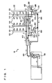
Fig. 1 is an overall schematic view of a fuel supply system of a gasoline engine controlled by a control device according to an embodiment of the present invention. -
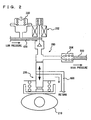
Fig. 2 is a partial enlarged view ofFig. 1 . -
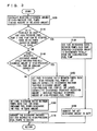
Figs. 3 and4 are flowcharts each illustrating a control structure of a program executed by an engine ECU. - Hereinafter, embodiments of the present invention will be described with reference to the drawings. In the following description, the same reference characters denote the same portions having the same names and functions. Thus, detailed description thereof will not be repeated.
-
Fig. 1 shows afuel supply system 10 of an engine controlled by an engine ECU (Electronic Control Unit) that is a control device according to an embodiment of the present invention. The engine is a V-type 8-cylinder gasoline engine, and has in-cylinder injectors 110 for injecting the fuel into the respective cylinders, andintake manifold injectors 120 for injecting the fuel into intake manifolds of the respective cylinders. It is noted that the present invention is not applied exclusively to such an engine, but is also applicable to a gasoline engine of another type and a common rail diesel engine. Further, the number of high-pressure fuel pumps is not restricted to two, but may be any number of more than one. - As shown in
Fig. 1 , thisfuel supply system 10 includes afeed pump 100 provided in a fuel tank and for supplying a fuel at a discharge pressure of low pressure (about 400 kPa corresponding to the pressure of a pressure regulator), a first high-pressure fuel pump 200 driven by afirst cam 210, a second high-pressure fuel pump 300 driven by asecond cam 310 having a discharge phase different from that offirst cam 210, a high-pressure delivery pipe 112 provided for each of left and right banks and for supplying a high-pressure fuel to in-cylinder injectors 110, four in-cylinder injectors 110 for each of the left and right banks, provided at the corresponding high-pressure delivery pipe 112, a low-pressure delivery pipe 122 provided for each of the left and right banks and for supplying a fuel tointake manifold injectors 120, and fourintake manifold injectors 120 for each of the left and right banks, provided at the corresponding low-pressure delivery pipe 122. - The discharge port of
feed pump 100 in the fuel tank is connected to a low-pressure supply pipe 400, which is branched into a first low-pressuredelivery connection pipe 410 and apump supply pipe 420. First low-pressuredelivery connection pipe 410 is branched to low-pressure delivery pipe 122 of one of the V-shaped banks, and on the downstream of that branch point, it forms a second low-pressuredelivery connection pipe 430, which is connected to low-pressure delivery pipe 122 of the other bank. -
Pump supply pipe 420 is connected to intake ports of first and second high-pressure fuel pumps first pulsation damper 220 and asecond pulsation damper 320 are provided immediately upstream of the intake ports of first and second high-pressure fuel pumps - The discharge port of first high-
pressure fuel pump 200 is connected to a first high-pressuredelivery connection pipe 500, which is connected to high-pressure delivery pipe 112 of one of the V-shaped banks. The discharge port of second high-pressure fuel pump 300 is connected to a second high-pressuredelivery connection pipe 510, which is connected to high-pressure delivery pipe 112 of the other bank. High-pressure delivery pipe 112 of one bank and high-pressure delivery pipe 112 of the other bank are connected via a high-pressure connection pipe 520. - A
relief valve 114 provided at high-pressure delivery pipe 112 is connected via a high-pressuredelivery return pipe 610 to a high-pressure fuelpump return pipe 600. The return ports of high-pressure fuel pumps pump return pipe 600. High-pressure fuelpump return pipe 600 is connected to returnpipes -
Fig. 2 is an enlarged view of first high-pressure fuel pump 200 and its surroundings inFig. 1 . Although second high-pressure fuel pump 300 has the similar configuration, they are different in phase of the cams and hence different in phase of the discharge timings, thereby suppressing occurrence of pulsation. First and second high-pressure fuel pumps pressure fuel pump 200 has discharge capability that is smaller than discharge capability of second high-pressure fuel pump 300. Such data is stored in a memory of the engine ECU. - High-
pressure fuel pump 200 has, as its main components, apump plunger 206 driven by acam 210 to slide up and down, anelectromagnetic spill valve 202, and acheck valve 204 provided with a leakage function. - When
pump plunger 206 is moved downward bycam 210 and whileelectromagnetic spill valve 202 is open, the fuel is introduced (suctioned). Whenpump plunger 206 is moved upward bycam 210, the timing to closeelectromagnetic spill valve 202 is changed to control the amount of the fuel discharged from high-pressure fuel pump 200. During the pressurizing stroke in which pumpplunger 206 is moved upward, the fuel of a greater amount is discharged as the timing to closeelectromagnetic spill valve 202 is earlier, whereas the fuel of a fewer amount is discharged as the timing to close the valve is later. The drive duty ofelectromagnetic spill valve 202 when the greatest amount of fuel is discharged is set to 100%, and the drive duty ofelectromagnetic spill valve 202 when the smallest amount of fuel is discharged is set to 0%. When the drive duty is 0%,electromagnetic spill valve 202 remains open, in which case, althoughpump plunger 206 slides up and down as long asfirst cam 210 continues to rotate (along with rotation of the engine), the fuel is not pressurized becauseelectromagnetic spill valve 202 does not close. - The pressurized fuel presses and opens
check valve 204 provided with the leakage function (of the set pressure of about 60 kPa), and the fuel is delivered via first high-pressuredelivery connection pipe 500 to high-pressure delivery pipe 112. At this time, the fuel pressure is controlled in a feedback manner by a fuel pressure sensor provided at high-pressure delivery pipe 112. High-pressure delivery pipes 112 at the respective banks are connected via high-pressure connection pipe 520, as described above. -
Check valve 204 with the leakage function is a check valve of a normal type but provided with pores that are always open. When the fuel pressure within first high-pressure fuel pump 200 (pump plunger 206) becomes lower than the fuel pressure within first high-pressure delivery connection pipe 500 (for example, when the engine and hencecam 210 stops whileelectromagnetic spill valve 202 remains open), the high-pressure fuel within first high-pressuredelivery connection pipe 500 returns through the pores back to the high-pressure fuel pump 200 side, thereby lowering the fuel pressure within high-pressuredelivery connection pipe 500 as well as within high-pressure delivery pipe 112. As such, at the time of stop of the engine, for example, the fuel within high-pressure delivery pipe 112 is not at a high pressure, so that leakage of the fuel from in-cylinder injectors 110 is prevented. - Hereinafter, a control structure of a program executed by the engine ECU implementing the control device according to the present embodiment will be described with reference to
Fig. 3 . - In step (hereinafter, abbreviated as "S") 100, the engine ECU calculates an amount of the fuel required to be discharged from the high-pressure fuel pumps (hereinafter, also referred to as a "required discharge amount of the high-pressure fuel pumps"). At this time, the amount of the fuel relieved from
check valve 204 with the leakage function is taken into account as well. InS 110, the engine ECU determines whether it is possible to stop one of the two high-pressure fuel pumps. For example, it is determined that one high-pressure fuel pump can be stopped when the amount of the fuel injected into the cylinder by in-cylinder injector 110 is zero. When it is determined that one of the high-pressure fuel pumps can be stopped (YES in S 110), the process goes to S120. If not (NO in S110), the process goes to S140. - In S120, the engine ECU sets the fuel discharge ratio between the two high-pressure fuel pumps such that the required discharge amount of the high-pressure fuel pumps is discharged totally from one high-pressure fuel pump that is not stopped. In S130, the engine ECU converts the discharge amount set for the high-pressure fuel pump in S120 to a duty.
- In S140, the engine ECU determines whether the required discharge amount of the high-pressure fuel pumps exceeds a maximum possible discharge amount of first high-
pressure fuel pump 200 of smaller capability. If the required discharge amount exceeds the maximum possible discharge amount of first high-pressure fuel pump 200 of smaller capability (YES in S140), the process goes to S150. If not (NO in S 140), the process goes to S 160. - In S150, the engine ECU sets the fuel discharge ratio between the two high-pressure fuel pumps as follows. The discharge amount of first high-pressure fuel pump 200 (of smaller capability) is set to its maximum possible discharge amount, and the discharge amount of second high-pressure fuel pump 300 (of larger capability) is set to: (required discharge amount - (maximum possible) discharge amount of first high-pressure fuel pump 200). The process then goes to S170.
- In S160, the engine ECU sets the fuel discharge ratio between the two high-pressure fuel pumps such that they discharge the fuel of equal or approximately equal amounts. In S170, the discharge amounts set for the respective high-pressure fuel pumps are converted to duties.
- An operation of the fuel supply system of an engine controlled by the engine ECU implementing the control device of the present embodiment based on the above-described structure and flowchart will now be described.
- The amount of the fuel required to be discharged from the high-pressure fuel pumps (i.e., the required discharge amount of the high-pressure fuel pumps) is calculated based on the engine speed, engine load and the like, with the amount of the fuel relieved from
check valve 204 having the leakage function taken into account (S100). When the amount of the fuel injected from in-cylinder injector 110 is zero during fuel cut, idling or the like, it is determined that one of the pumps can be stopped (YES in S110). In this case, the fuel discharge ratio between the pumps is set such that the required discharge amount of the high-pressure fuel pumps is discharged by only one high-pressure fuel pump (S120), and the relevant discharge amount is converted to a duty (S130). - If it is determined that one of the high-pressure fuel pumps cannot be stopped (NO in S110), it is determined whether the required discharge amount of the high-pressure fuel pumps exceeds a maximum possible discharge amount of first high-
pressure fuel pump 200 of smaller capability (S140). If the required discharge amount exceeds the maximum possible discharge amount of first high-pressure fuel pump 200 of smaller capability (YES in S140), the fuel discharge ratio between the pumps is set such that first high-pressure fuel pump 200 (of small capability) will discharge the fuel of its maximum possible discharge amount and second high-pressure fuel pump 300 (of large capability) will discharge the fuel of an amount obtained by subtracting the (maximum possible) discharge amount of first high-pressure fuel pump 200 from the required discharge amount of the high-pressure fuel pumps. - If the required discharge amount of the high-pressure fuel pumps is smaller than the maximum possible discharge amount of first high-
pressure fuel pump 200 of smaller capability (NO in S140), then the fuel discharge ratio between the pumps is set such that the two pumps will discharge the fuel in equal (or approximately equal) amount. - When both high-pressure fuel pumps are to be used, the discharge amounts set for the respective high-pressure fuel pumps are converted to duties (S170).
- The engine ECU transmits control signals corresponding to the converted duties to the electromagnetic spill valves, so as to control the amounts of the fuel discharged from high-
pressure fuel pumps - As described above, according to the fuel supply system of an engine controlled by the engine ECU implementing the control device of the present embodiment, the amount of the fuel required to be discharged from the high-pressure fuel pumps is calculated with the amount of the fuel relieved from the check valve having the leakage function being taken into account. As such, even in the case where only one of the pumps is activated while the amount of the relieved fuel increases as the other pump is stopped, the amount of the relieved fuel is included in the calculation, and thus, it is possible to calculate the required discharge amount so as not to induce overload. Further, the system allows only one of the high-pressure fuel pumps to operate when it is possible to stop the other pump. Still further, the fuel discharge ratio between the two high-pressure pumps is set to cause the two pumps to discharge the fuel in equal (or approximately equal) amount until the amount of the fuel required to be discharged from the high-pressure fuel pumps exceeds a maximum possible discharge amount of the pump of smaller capability. When the amount of the fuel required to be discharged from the high-pressure fuel pumps exceeds the maximum possible discharge amount of the high-pressure fuel pump of smaller capability, the fuel discharge ratio between the pumps is set such that the high-pressure fuel pump of smaller capability discharges the fuel of its maximum possible discharge amount and the high-pressure fuel pump of larger capability discharges the fuel of the amount obtained by subtracting the discharge amount of the high-pressure fuel pump of smaller capability from the amount of the fuel required to be discharged from the high-pressure fuel pumps. Accordingly, the overall efficiency of the fuel supply system as well as safety thereof can be improved, and the cooperative control of the plurality of high-pressure fuel pumps becomes possible.
- Hereinafter, a control device according to a modification of the present invention will be described. The control device according to the modification executes a program that is different from the one executed in the above-described embodiment. Otherwise, the hardware configuration (
Figs. 1 and2 ) is identical, so that detailed description thereof will not be repeated. - A control structure of a program executed by an engine ECU implementing the control device according to the modification will now be described with reference to
Fig. 4 . Hereinafter, the number of high-pressure fuel pumps is set to N. - In S200, the engine ECU initializes the variable I (I = 1). In S210, the engine ECU drives a high-pressure fuel pump (I). At this time, a predetermined duty is transmitted to electromagnetic spill valve 2.02. In S220, the engine ECU determines whether the fuel pressure has been increased. The determination is made based on a signal input to the engine ECU from a fuel pressure sensor provided at high-
pressure delivery pipe 500. If the fuel pressure has been increased (YES in 5220), the process goes to 5230. If not (NO in S220), the process goes to S240. - In S230, the engine ECU determines that the high-pressure fuel pump (I) is normal. The process then goes to S250.
- In S240, the engine ECU determines that the high-pressure fuel pump (I) is faulty.
- In S250, the engine ECU stops the high-pressure fuel pump (I). At this time, it controls the control duty to 0%.
- In S260, the engine ECU increments the variable I by 1. In S270, the engine ECU determines whether the variable I is equal to or greater than the number N of pumps. If the variable I≥ the number N of high-pressure fuel pumps (YES in S270), it is determined that failure diagnosis has been finished for all the high-pressure fuel pumps, and the process is ended. If not (NO in S270), the process returns to S210, and the failure diagnosis is carried out for the next high-pressure fuel pump. The process in S270 may be configured to determine whether the variable I = the number N of high-pressure fuel pumps.
- As described above, according to the fuel supply system controlled by the engine ECU implementing the control device of the present modification, it is readily possible to locate a malfunctioning high-pressure fuel pump in the system formed ofN high-pressure fuel pumps.
- It should be understood that the embodiments disclosed herein are illustrative and non-restrictive in every respect. The scope of the present invention is defined by the terms of the claims, rather than the description above.
Claims (20)
- A control device of a high-pressure fuel system of an internal combustion engine having a fuel injection mechanism for injecting a fuel into a cylinder, the high-pressure fuel system including a plurality of high-pressure fuel pumps driven by the internal combustion engine, the control device comprising:a detection unit for detecting an amount of the fuel required to be discharged from said high-pressure fuel pumps; anda control unit for controlling said plurality of high-pressure fuel pumps, while permitting a stop of fuel supply from at least one of said plurality of high-pressure fuel pumps, such that the fuel discharged from the remaining of said plurality of high-pressure fuel pumps is supplied to a plurality of such fuel injection mechanisms,said control unit including a discharge ratio determination portion that determines a fuel discharge ratio among said plurality of high-pressure fuel pumps in accordance with said amount of the fuel required to be discharged by said remaining plurality of high-pressure fuel pumps in a period when at least one of said plurality of pumps is stopped.
- The control device of a high-pressure fuel system of an internal combustion engine according to claim 1, further comprising a storage unit for storing a characteristic of each of said high-pressure fuel pumps, wherein
said discharge ratio determination portion determines the fuel discharge ratio among said plurality of high-pressure fuel pumps in accordance with said amount of the fuel required to be discharged, based on said characteristics. - The control device of a high-pressure fuel system of an internal combustion engine according to claim 1, wherein said discharge ratio determination portion calculates an amount of the fuel to be discharged from each of said high-pressure fuel pumps based on said fuel discharge ratio, and calculates a drive duty of each of said high-pressure fuel pumps based on said amount of the fuel to be discharged therefrom.
- The control device of a high-pressure fuel system of an internal combustion engine according to claim 1, wherein said discharge ratio determination portion determines the fuel discharge ratio among said plurality of high-pressure fuel pumps in accordance with said amount of the fuel required to be discharged, with an amount of the fuel relieved from said high-pressure fuel pumps being taken into account.
- The control device of a high-pressure fuel system of an internal combustion engine according to claim 4, wherein said control unit determines whether it is possible to stop discharge of the fuel from at least one of said high-pressure fuel pumps in accordance with said amount of the fuel required to be discharged.
- The control device of a high-pressure fuel system of an internal combustion engine according to claim 1, wherein said control unit controls said high-pressure fuel pumps such that discharge of the fuel from at least one of said high-pressure fuel pumps is stopped when fuel injection from said fuel injection mechanism is stopped.
- The control device of a high-pressure fuel system of an internal combustion engine according to claim 1, wherein when said plurality of high-pressure fuel pumps include a high-pressure fuel pump having a different discharge characteristic, said discharge ratio determination portion determines the fuel discharge ratio among said plurality of high-pressure fuel pumps such that the amount of the fuel discharged from the high-pressure fuel pump having the different discharge characteristic is approximately equal to the amount of the fuel discharged from another one of said high-pressure fuel pumps.
- The control device of a high-pressure fuel system of an internal combustion engine according to any of claims 1-7, wherein when at least one of said plurality of high-pressure fuel pumps has a maximum possible discharge amount that is smaller than said amount of the fuel required to be discharged, said discharge ratio determination portion determines the fuel discharge ratio among said plurality of high-pressure fuel pumps such that the high-pressure fuel pump having its maximum possible discharge amount smaller than said amount of the fuel required to be discharged will discharge the fuel of the maximum possible discharge amount and that another one of said high-pressure fuel pumps will discharge the fuel of the amount corresponding to a difference between said amount of the fuel required to be discharged and said maximum possible discharges amount.
- The control device of a high-pressure fuel system of an internal combustion engine according to claim 1, further comprising:an operation unit for activating said plurality of high-pressure fuel pumps one by one using a predetermined drive duty; anda determination unit for determining whether the pump is faulty or not based on a change in fuel pressure as a result of said activation.
- The control device of a high-pressure fuel system of an internal combustion engine according to claim 9, wherein said determination unit determines whether the pump is faulty or not based on a degree of increase of said fuel pressure.
- A method of controlling a high-pressure fuel system of an internal combustion engine having fuel injection means for injecting a fuel into a cylinder, the high-pressure fuel system including a plurality of high-pressure fuel pumps driven by the internal combustion engine, the method comprising the steps of:detecting by means of a detection means an amount of the fuel required to be discharged from said high-pressure fuel pumps; andcontrolling said plurality of high-pressure fuel pumps, while permitting a stop of fuel supply from at least one of said plurality of high-pressure fuel pumps such that the fuel discharged from the remaining of said plurality of high-pressure fuel pumps is supplied to a plurality of such fuel injection mechanisms,determining a fuel discharge ratio among said plurality of high-pressure fuel pumps in accordance with said amount of the fuel required to be discharged by said remaining plurality of high-pressure fuel pumps in a period when at least one of said plurality of pumps is stopped.
- The method according to claim 11, further comprising storage means for storing a characteristic of each of said high-pressure fuel pumps, wherein,
said discharge ratio determination means includes means determining the fuel discharge ratio among said plurality of high-pressure fuel pumps in accordance with said amounts of the fuel required to be discharged, based on said characteristics. - The method according to claim 11, wherein said discharge ratio determination means includes
means calculating an amount of the fuel to be discharged from each of said high-pressure fuel pumps based on said fuel discharge ratio, and
means calculating a drive duty of each of said high-pressure fuel pumps based on said amounts of the fuel to be discharged therefrom. - The method according to claim 11, wherein said discharge ratio determination means includes means determining the fuel discharge ratio among said plurality of high-pressure fuel pumps in accordance with said amount of the fuel required to be discharged, with an amount of the fuel relieved from said high-pressure fuel pumps being taken into account.
- The method according to claim 14, wherein said control means further includes means determining whether it is possible to stop discharge of the fuel from at least one of said high-pressure fuel pumps in accordance with said amount of the fuel required to be discharged.
- The method according to claim 11, wherein said control means further includes means controlling said high-pressure fuel pumps such that discharge of the fuel from at least one of said high-pressure fuel pumps is stopped when fuel injection from said fuel injection means is stopped.
- The method according to claim 11, wherein said discharge ratio determination means includes means determining the fuel discharge ratio among said plurality of high-pressure fuel pumps such that, when said plurality of high-pressure fuel pumps include a high-pressure fuel pump having a different discharge characteristic, the amount of the fuel discharged from the high-pressure fuel pump having the different discharge characteristic is approximately equal to the amount of the fuel discharged from another one of said high-pressure fuel pumps.
- The method according to any of claims 11-17, wherein said discharge ratio determination means includes means determining the fuel discharge ratio among said plurality of high-pressure fuel pumps such that, when at least one of said plurality of high-pressure fuel pumps has a maximum possible discharge amount that is smaller than said amount of the fuel required to be discharged, the high-pressure fuel pump having its maximum possible discharge amount smaller than said amount of the fuel required to be discharged will discharge the fuel of the maximum possible discharge amount and that another one of said high-pressure fuel pumps will discharge the fuel of the amount corresponding to a difference between said amount of the fuel required to be discharged and said maximum possible discharge amount.
- The method according to claim 11, further comprising:operation means activating said plurality of high-pressure fuel pumps one by one using a predetermined drive duty; anddetermination means determining whether the pump is faulty or not based on a change in fuel pressure as a result of said activation.
- The method according to claim 19, wherein said determination means includes means determining whether the pump is faulty or not based on a degree of increase of said fuel pressure.
Applications Claiming Priority (2)
| Application Number | Priority Date | Filing Date | Title |
|---|---|---|---|
| JP2004222773A JP4438553B2 (en) | 2004-07-30 | 2004-07-30 | Control device for high pressure fuel system of internal combustion engine |
| PCT/JP2005/011894 WO2006011330A2 (en) | 2004-07-30 | 2005-06-22 | Control device of high-pressure fuel system of an internal combustion engine |
Publications (2)
| Publication Number | Publication Date |
|---|---|
| EP1797307A2 EP1797307A2 (en) | 2007-06-20 |
| EP1797307B1 true EP1797307B1 (en) | 2009-09-23 |
Family
ID=34979455
Family Applications (1)
| Application Number | Title | Priority Date | Filing Date |
|---|---|---|---|
| EP05755877A Expired - Fee Related EP1797307B1 (en) | 2004-07-30 | 2005-06-22 | Control device of high-pressure fuel system of an internal combustion engine |
Country Status (6)
| Country | Link |
|---|---|
| US (1) | US7107968B2 (en) |
| EP (1) | EP1797307B1 (en) |
| JP (1) | JP4438553B2 (en) |
| CN (1) | CN1989331B (en) |
| DE (1) | DE602005016824D1 (en) |
| WO (1) | WO2006011330A2 (en) |
Families Citing this family (29)
| Publication number | Priority date | Publication date | Assignee | Title |
|---|---|---|---|---|
| DE10315318A1 (en) * | 2003-04-04 | 2004-10-14 | Robert Bosch Gmbh | Method for operating an internal combustion engine |
| WO2006004026A2 (en) * | 2004-07-02 | 2006-01-12 | Toyota Jidosha Kabushiki Kaisha | Fuel supply system for internal combustion engine |
| JP4508020B2 (en) * | 2005-07-13 | 2010-07-21 | トヨタ自動車株式会社 | Diagnostic device for electromagnetic relief valve in fuel supply system |
| JP4165572B2 (en) * | 2006-04-12 | 2008-10-15 | トヨタ自動車株式会社 | Fuel supply device for internal combustion engine |
| JP4657140B2 (en) * | 2006-04-24 | 2011-03-23 | 日立オートモティブシステムズ株式会社 | Engine fuel supply system |
| DE102006046840A1 (en) * | 2006-10-02 | 2008-04-03 | Robert Bosch Gmbh | Process for monitoring a fuel injection system recognizes an error when a first value and/or a second value deviate from an expected value |
| JP4215094B2 (en) * | 2006-11-20 | 2009-01-28 | トヨタ自動車株式会社 | Control device for internal combustion engine |
| JP4672640B2 (en) * | 2006-11-30 | 2011-04-20 | 三菱重工業株式会社 | Engine fuel injection apparatus and operation method |
| SE530779C2 (en) * | 2007-01-08 | 2008-09-09 | Scania Cv Ab | Fuel pump and a method for controlling a fuel pump |
| DE102007006865A1 (en) * | 2007-02-12 | 2008-08-14 | Siemens Ag | Internal combustion engine controlling method for use in motor vehicle, involves operating high-pressure pumps in normal mode of operation, in which two pumps together supply fuel to pressure reservoir |
| DE102007060634A1 (en) * | 2007-12-17 | 2009-06-18 | Robert Bosch Gmbh | Method for operating an internal combustion engine |
| DE102008000711A1 (en) * | 2008-03-17 | 2009-09-24 | Robert Bosch Gmbh | high pressure pump |
| JP5126106B2 (en) * | 2009-02-18 | 2013-01-23 | 株式会社デンソー | Fuel supply device |
| US7950371B2 (en) * | 2009-04-15 | 2011-05-31 | GM Global Technology Operations LLC | Fuel pump control system and method |
| US7987704B2 (en) * | 2009-05-21 | 2011-08-02 | GM Global Technology Operations LLC | Fuel system diagnostic systems and methods |
| JP5191983B2 (en) * | 2009-12-16 | 2013-05-08 | 日立オートモティブシステムズ株式会社 | Diagnostic device for internal combustion engine |
| DE102009059672B4 (en) * | 2009-12-19 | 2013-05-08 | Deutz Ag | Internal combustion engine with a high pressure injection system and method |
| WO2012098661A1 (en) * | 2011-01-20 | 2012-07-26 | トヨタ自動車株式会社 | Control device for internal combustion engine |
| US8820299B2 (en) | 2011-04-27 | 2014-09-02 | Toyota Jidosha Kabushiki Kaisha | Fuel injection control system for internal combustion engine |
| KR101592402B1 (en) * | 2013-12-17 | 2016-02-05 | 현대자동차주식회사 | Diagnostics method and system for gasoline direct injection engine |
| CN104481715B (en) * | 2014-12-03 | 2017-01-25 | 中国第一汽车股份有限公司无锡油泵油嘴研究所 | Fault detection method of high-pressure fuel pump |
| DE102015207700B4 (en) * | 2015-04-27 | 2018-12-20 | Continental Automotive Gmbh | Method for controlling a fuel delivery system |
| ITUA20163392A1 (en) * | 2016-05-12 | 2017-11-12 | Magneti Marelli Spa | METHOD OF CONTROL OF A FUEL PUMP FOR A DIRECT INJECTION SYSTEM |
| WO2018081115A1 (en) * | 2016-10-24 | 2018-05-03 | Cummins Inc. | Fuel pump pressure control structure and methodology |
| US10539090B2 (en) * | 2017-10-19 | 2020-01-21 | Fca Us Llc | Fuel system with deactivating fuel pump |
| JP6973010B2 (en) * | 2017-12-13 | 2021-11-24 | トヨタ自動車株式会社 | Fuel pump controller |
| JP6922713B2 (en) * | 2017-12-13 | 2021-08-18 | トヨタ自動車株式会社 | Fuel pump controller |
| JP7091757B2 (en) * | 2018-03-22 | 2022-06-28 | いすゞ自動車株式会社 | Abnormality diagnosis device and abnormality diagnosis method |
| USD959780S1 (en) | 2020-06-01 | 2022-08-02 | Alpha Scooper, Inc. | Waste scooper |
Family Cites Families (17)
| Publication number | Priority date | Publication date | Assignee | Title |
|---|---|---|---|---|
| US5230613A (en) * | 1990-07-16 | 1993-07-27 | Diesel Technology Company | Common rail fuel injection system |
| JP2766722B2 (en) | 1990-10-09 | 1998-06-18 | 三菱重工業株式会社 | Electro-hydraulic control device for internal combustion engine |
| JP2689721B2 (en) | 1990-11-16 | 1997-12-10 | トヨタ自動車株式会社 | Fuel pressure control device for internal combustion engine |
| JP3033214B2 (en) * | 1991-02-27 | 2000-04-17 | 株式会社デンソー | Accumulation type fuel supply method and apparatus by a plurality of fuel pumping means, and abnormality determination apparatus in equipment having a plurality of fluid pumping means |
| DE4335171C1 (en) * | 1993-10-15 | 1995-05-04 | Daimler Benz Ag | Fuel injection system for a multi-cylinder diesel internal combustion engine |
| JPH0968086A (en) * | 1995-08-31 | 1997-03-11 | Nissan Motor Co Ltd | Fuel pump |
| US5676114A (en) | 1996-07-25 | 1997-10-14 | Cummins Engine Company, Inc. | Needle controlled fuel system with cyclic pressure generation |
| JP3339326B2 (en) | 1996-09-20 | 2002-10-28 | トヨタ自動車株式会社 | Fuel supply device |
| JPH10274075A (en) | 1997-03-28 | 1998-10-13 | Mitsubishi Motors Corp | Cylinder injection internal combustion engine with cam driving type fuel pump, and cylinder injection internal combustion engine with parallel arrangement type fuel feed system |
| DE19737968C1 (en) * | 1997-08-30 | 1998-12-10 | Daimler Benz Ag | Fuel injector for multiple cylinder internal combustion engine |
| US6076504A (en) * | 1998-03-02 | 2000-06-20 | Cummins Engine Company, Inc. | Apparatus for diagnosing failures and fault conditions in a fuel system of an internal combustion engine |
| DE19823639A1 (en) * | 1998-05-27 | 1999-12-02 | Bosch Gmbh Robert | Fuel supply system of an internal combustion engine |
| DE19955617B4 (en) * | 1999-11-19 | 2004-05-19 | Mtu Friedrichshafen Gmbh | Method for controlling an internal combustion engine with two high-pressure pumps |
| DE10023033A1 (en) * | 2000-05-11 | 2001-11-22 | Bosch Gmbh Robert | Operation of fuel metering system of direct injection engine, places all high pressure pumps in fuel circuit, with common pressure control system |
| US6932583B2 (en) * | 2001-04-16 | 2005-08-23 | Siemens Diesel Systems Technology | Multiple stage pump with multiple external control valves |
| JP4123952B2 (en) * | 2003-02-06 | 2008-07-23 | トヨタ自動車株式会社 | Fuel supply system for internal combustion engine |
| DE10341788B4 (en) * | 2003-09-10 | 2005-08-11 | Siemens Ag | Method and device for monitoring a fuel supply device of an internal combustion engine |
-
2004
- 2004-07-30 JP JP2004222773A patent/JP4438553B2/en not_active Expired - Fee Related
-
2005
- 2005-06-22 CN CN2005800252158A patent/CN1989331B/en not_active Expired - Fee Related
- 2005-06-22 EP EP05755877A patent/EP1797307B1/en not_active Expired - Fee Related
- 2005-06-22 WO PCT/JP2005/011894 patent/WO2006011330A2/en active Application Filing
- 2005-06-22 DE DE602005016824T patent/DE602005016824D1/en active Active
- 2005-06-24 US US11/165,296 patent/US7107968B2/en active Active
Also Published As
| Publication number | Publication date |
|---|---|
| CN1989331A (en) | 2007-06-27 |
| WO2006011330A2 (en) | 2006-02-02 |
| WO2006011330A3 (en) | 2006-03-23 |
| JP4438553B2 (en) | 2010-03-24 |
| JP2006037920A (en) | 2006-02-09 |
| EP1797307A2 (en) | 2007-06-20 |
| DE602005016824D1 (en) | 2009-11-05 |
| US7107968B2 (en) | 2006-09-19 |
| US20060021598A1 (en) | 2006-02-02 |
| CN1989331B (en) | 2010-05-05 |
Similar Documents
| Publication | Publication Date | Title |
|---|---|---|
| EP1797307B1 (en) | Control device of high-pressure fuel system of an internal combustion engine | |
| US8014932B2 (en) | Fuel injection controller for internal combustion engine | |
| JP4297160B2 (en) | Internal combustion engine | |
| JP4179333B2 (en) | Start control device for internal combustion engine | |
| US7328687B2 (en) | Fuel supply apparatus for internal combustion engine | |
| US8800355B2 (en) | Pressure accumulation fuel injection device | |
| US7073486B2 (en) | Fuel pressure control device of internal combustion engine | |
| WO2014184628A1 (en) | Fuel supply apparatus for internal combustion engine | |
| EP1792074A1 (en) | High-pressure fuel supply apparatus of internal combustion engine and method of designing the same | |
| JP2013231362A (en) | Fuel pressure control device | |
| JP5353831B2 (en) | Fuel supply device for internal combustion engine | |
| US7891341B2 (en) | Control device for internal combustion engine | |
| JP4604842B2 (en) | Abnormality judgment device for fuel system of internal combustion engine | |
| JP3377034B2 (en) | Accumulator type fuel injection device | |
| JP2007247520A (en) | Fuel supply system for internal combustion engine | |
| JP2006220112A (en) | High-pressure fuel feeder of internal combustion engine | |
| JP2007040226A (en) | Fuel supply device for internal combustion engine | |
| JP4356667B2 (en) | Fuel supply device for internal combustion engine | |
| JP2007071082A (en) | Fuel injector of internal combustion engine | |
| JP2000161114A (en) | Accumulating fuel injection device | |
| JP2000161172A (en) | Accumulator type fuel injection device | |
| JP2009144727A (en) | Fuel feed system of internal combustion engine | |
| JP2000161169A (en) | Accumulator type fuel injection device | |
| JP2006029094A (en) | Pressure accumulating fuel injector and internal combustion engine having its pressure accumulating fuel injector |
Legal Events
| Date | Code | Title | Description |
|---|---|---|---|
| PUAI | Public reference made under article 153(3) epc to a published international application that has entered the european phase |
Free format text: ORIGINAL CODE: 0009012 |
|
| 17P | Request for examination filed |
Effective date: 20070227 |
|
| AK | Designated contracting states |
Kind code of ref document: A2 Designated state(s): DE FR GB IT |
|
| DAX | Request for extension of the european patent (deleted) | ||
| RBV | Designated contracting states (corrected) |
Designated state(s): DE FR GB IT |
|
| 17Q | First examination report despatched |
Effective date: 20080617 |
|
| GRAP | Despatch of communication of intention to grant a patent |
Free format text: ORIGINAL CODE: EPIDOSNIGR1 |
|
| GRAS | Grant fee paid |
Free format text: ORIGINAL CODE: EPIDOSNIGR3 |
|
| GRAA | (expected) grant |
Free format text: ORIGINAL CODE: 0009210 |
|
| AK | Designated contracting states |
Kind code of ref document: B1 Designated state(s): DE FR GB IT |
|
| REG | Reference to a national code |
Ref country code: GB Ref legal event code: FG4D |
|
| REF | Corresponds to: |
Ref document number: 602005016824 Country of ref document: DE Date of ref document: 20091105 Kind code of ref document: P |
|
| PLBE | No opposition filed within time limit |
Free format text: ORIGINAL CODE: 0009261 |
|
| STAA | Information on the status of an ep patent application or granted ep patent |
Free format text: STATUS: NO OPPOSITION FILED WITHIN TIME LIMIT |
|
| 26N | No opposition filed |
Effective date: 20100624 |
|
| REG | Reference to a national code |
Ref country code: GB Ref legal event code: 746 Effective date: 20130326 |
|
| REG | Reference to a national code |
Ref country code: DE Ref legal event code: R082 Ref document number: 602005016824 Country of ref document: DE Representative=s name: WINTER, BRANDL, FUERNISS, HUEBNER, ROESS, KAIS, DE |
|
| REG | Reference to a national code |
Ref country code: DE Ref legal event code: R084 Ref document number: 602005016824 Country of ref document: DE Effective date: 20130319 |
|
| REG | Reference to a national code |
Ref country code: FR Ref legal event code: PLFP Year of fee payment: 12 |
|
| REG | Reference to a national code |
Ref country code: FR Ref legal event code: PLFP Year of fee payment: 13 |
|
| PGFP | Annual fee paid to national office [announced via postgrant information from national office to epo] |
Ref country code: GB Payment date: 20170621 Year of fee payment: 13 Ref country code: FR Payment date: 20170511 Year of fee payment: 13 |
|
| PGFP | Annual fee paid to national office [announced via postgrant information from national office to epo] |
Ref country code: IT Payment date: 20170619 Year of fee payment: 13 |
|
| GBPC | Gb: european patent ceased through non-payment of renewal fee |
Effective date: 20180622 |
|
| PG25 | Lapsed in a contracting state [announced via postgrant information from national office to epo] |
Ref country code: IT Free format text: LAPSE BECAUSE OF NON-PAYMENT OF DUE FEES Effective date: 20180622 Ref country code: FR Free format text: LAPSE BECAUSE OF NON-PAYMENT OF DUE FEES Effective date: 20180630 Ref country code: GB Free format text: LAPSE BECAUSE OF NON-PAYMENT OF DUE FEES Effective date: 20180622 |
|
| PGFP | Annual fee paid to national office [announced via postgrant information from national office to epo] |
Ref country code: DE Payment date: 20190612 Year of fee payment: 15 |
|
| REG | Reference to a national code |
Ref country code: DE Ref legal event code: R119 Ref document number: 602005016824 Country of ref document: DE |
|
| PG25 | Lapsed in a contracting state [announced via postgrant information from national office to epo] |
Ref country code: DE Free format text: LAPSE BECAUSE OF NON-PAYMENT OF DUE FEES Effective date: 20210101 |