EP1796255A1 - Air conditioner - Google Patents
Air conditioner Download PDFInfo
- Publication number
- EP1796255A1 EP1796255A1 EP05743295A EP05743295A EP1796255A1 EP 1796255 A1 EP1796255 A1 EP 1796255A1 EP 05743295 A EP05743295 A EP 05743295A EP 05743295 A EP05743295 A EP 05743295A EP 1796255 A1 EP1796255 A1 EP 1796255A1
- Authority
- EP
- European Patent Office
- Prior art keywords
- circuit
- current
- inverter
- compressors
- air conditioning
- Prior art date
- Legal status (The legal status is an assumption and is not a legal conclusion. Google has not performed a legal analysis and makes no representation as to the accuracy of the status listed.)
- Granted
Links
Images


Classifications
-
- H—ELECTRICITY
- H02—GENERATION; CONVERSION OR DISTRIBUTION OF ELECTRIC POWER
- H02M—APPARATUS FOR CONVERSION BETWEEN AC AND AC, BETWEEN AC AND DC, OR BETWEEN DC AND DC, AND FOR USE WITH MAINS OR SIMILAR POWER SUPPLY SYSTEMS; CONVERSION OF DC OR AC INPUT POWER INTO SURGE OUTPUT POWER; CONTROL OR REGULATION THEREOF
- H02M5/00—Conversion of AC power input into AC power output, e.g. for change of voltage, for change of frequency, for change of number of phases
- H02M5/40—Conversion of AC power input into AC power output, e.g. for change of voltage, for change of frequency, for change of number of phases with intermediate conversion into DC
- H02M5/42—Conversion of AC power input into AC power output, e.g. for change of voltage, for change of frequency, for change of number of phases with intermediate conversion into DC by static converters
- H02M5/44—Conversion of AC power input into AC power output, e.g. for change of voltage, for change of frequency, for change of number of phases with intermediate conversion into DC by static converters using discharge tubes or semiconductor devices to convert the intermediate DC into AC
- H02M5/453—Conversion of AC power input into AC power output, e.g. for change of voltage, for change of frequency, for change of number of phases with intermediate conversion into DC by static converters using discharge tubes or semiconductor devices to convert the intermediate DC into AC using devices of a triode or transistor type requiring continuous application of a control signal
- H02M5/458—Conversion of AC power input into AC power output, e.g. for change of voltage, for change of frequency, for change of number of phases with intermediate conversion into DC by static converters using discharge tubes or semiconductor devices to convert the intermediate DC into AC using devices of a triode or transistor type requiring continuous application of a control signal using semiconductor devices only
-
- F—MECHANICAL ENGINEERING; LIGHTING; HEATING; WEAPONS; BLASTING
- F25—REFRIGERATION OR COOLING; COMBINED HEATING AND REFRIGERATION SYSTEMS; HEAT PUMP SYSTEMS; MANUFACTURE OR STORAGE OF ICE; LIQUEFACTION SOLIDIFICATION OF GASES
- F25B—REFRIGERATION MACHINES, PLANTS OR SYSTEMS; COMBINED HEATING AND REFRIGERATION SYSTEMS; HEAT PUMP SYSTEMS
- F25B49/00—Arrangement or mounting of control or safety devices
- F25B49/02—Arrangement or mounting of control or safety devices for compression type machines, plants or systems
- F25B49/025—Motor control arrangements
-
- H—ELECTRICITY
- H02—GENERATION; CONVERSION OR DISTRIBUTION OF ELECTRIC POWER
- H02P—CONTROL OR REGULATION OF ELECTRIC MOTORS, ELECTRIC GENERATORS OR DYNAMO-ELECTRIC CONVERTERS; CONTROLLING TRANSFORMERS, REACTORS OR CHOKE COILS
- H02P5/00—Arrangements specially adapted for regulating or controlling the speed or torque of two or more electric motors
- H02P5/74—Arrangements specially adapted for regulating or controlling the speed or torque of two or more electric motors controlling two or more AC dynamo-electric motors
-
- F—MECHANICAL ENGINEERING; LIGHTING; HEATING; WEAPONS; BLASTING
- F25—REFRIGERATION OR COOLING; COMBINED HEATING AND REFRIGERATION SYSTEMS; HEAT PUMP SYSTEMS; MANUFACTURE OR STORAGE OF ICE; LIQUEFACTION SOLIDIFICATION OF GASES
- F25B—REFRIGERATION MACHINES, PLANTS OR SYSTEMS; COMBINED HEATING AND REFRIGERATION SYSTEMS; HEAT PUMP SYSTEMS
- F25B2400/00—Component parts or details not otherwise provided for in this subclass
- F25B2400/07—Details of compressors or related parts
- F25B2400/075—Details of compressors or related parts with parallel compressors
-
- F—MECHANICAL ENGINEERING; LIGHTING; HEATING; WEAPONS; BLASTING
- F25—REFRIGERATION OR COOLING; COMBINED HEATING AND REFRIGERATION SYSTEMS; HEAT PUMP SYSTEMS; MANUFACTURE OR STORAGE OF ICE; LIQUEFACTION SOLIDIFICATION OF GASES
- F25B—REFRIGERATION MACHINES, PLANTS OR SYSTEMS; COMBINED HEATING AND REFRIGERATION SYSTEMS; HEAT PUMP SYSTEMS
- F25B2600/00—Control issues
- F25B2600/02—Compressor control
- F25B2600/021—Inverters therefor
-
- F—MECHANICAL ENGINEERING; LIGHTING; HEATING; WEAPONS; BLASTING
- F25—REFRIGERATION OR COOLING; COMBINED HEATING AND REFRIGERATION SYSTEMS; HEAT PUMP SYSTEMS; MANUFACTURE OR STORAGE OF ICE; LIQUEFACTION SOLIDIFICATION OF GASES
- F25B—REFRIGERATION MACHINES, PLANTS OR SYSTEMS; COMBINED HEATING AND REFRIGERATION SYSTEMS; HEAT PUMP SYSTEMS
- F25B2700/00—Sensing or detecting of parameters; Sensors therefor
- F25B2700/15—Power, e.g. by voltage or current
-
- F—MECHANICAL ENGINEERING; LIGHTING; HEATING; WEAPONS; BLASTING
- F25—REFRIGERATION OR COOLING; COMBINED HEATING AND REFRIGERATION SYSTEMS; HEAT PUMP SYSTEMS; MANUFACTURE OR STORAGE OF ICE; LIQUEFACTION SOLIDIFICATION OF GASES
- F25B—REFRIGERATION MACHINES, PLANTS OR SYSTEMS; COMBINED HEATING AND REFRIGERATION SYSTEMS; HEAT PUMP SYSTEMS
- F25B2700/00—Sensing or detecting of parameters; Sensors therefor
- F25B2700/21—Temperatures
- F25B2700/2104—Temperatures of an indoor room or compartment
-
- H—ELECTRICITY
- H02—GENERATION; CONVERSION OR DISTRIBUTION OF ELECTRIC POWER
- H02M—APPARATUS FOR CONVERSION BETWEEN AC AND AC, BETWEEN AC AND DC, OR BETWEEN DC AND DC, AND FOR USE WITH MAINS OR SIMILAR POWER SUPPLY SYSTEMS; CONVERSION OF DC OR AC INPUT POWER INTO SURGE OUTPUT POWER; CONTROL OR REGULATION THEREOF
- H02M1/00—Details of apparatus for conversion
- H02M1/0067—Converter structures employing plural converter units, other than for parallel operation of the units on a single load
- H02M1/008—Plural converter units for generating at two or more independent and non-parallel outputs, e.g. systems with plural point of load switching regulators
-
- Y—GENERAL TAGGING OF NEW TECHNOLOGICAL DEVELOPMENTS; GENERAL TAGGING OF CROSS-SECTIONAL TECHNOLOGIES SPANNING OVER SEVERAL SECTIONS OF THE IPC; TECHNICAL SUBJECTS COVERED BY FORMER USPC CROSS-REFERENCE ART COLLECTIONS [XRACs] AND DIGESTS
- Y02—TECHNOLOGIES OR APPLICATIONS FOR MITIGATION OR ADAPTATION AGAINST CLIMATE CHANGE
- Y02B—CLIMATE CHANGE MITIGATION TECHNOLOGIES RELATED TO BUILDINGS, e.g. HOUSING, HOUSE APPLIANCES OR RELATED END-USER APPLICATIONS
- Y02B30/00—Energy efficient heating, ventilation or air conditioning [HVAC]
- Y02B30/70—Efficient control or regulation technologies, e.g. for control of refrigerant flow, motor or heating
Definitions
- the present invention relates to an air conditioning apparatus having a plurality of compressors driven by respective inverter circuits.
- the air conditioning apparatus has heretofore been proposed an air conditioning apparatus having two capacity variable compressors driven and controlled by respective separate inverter circuits (for example, refer to Japanese Patent No. 2557903 ).
- the air conditioning apparatus is provided with a refrigerating cycle in which the exhaust side of the two compressors is connected to one refrigerant pipe in a shared manner and the intake side thereof is also connected to one refrigerant pipe in a shared manner.
- the power source circuit driving the two compressors in such air conditioning apparatus includes one which rectifies alternating current from an AC power source by use of one rectifier circuit, converts an output of the rectifier circuit into alternating current of variable frequency by use of two inverter circuits and then supplies the respective alternating currents to the corresponding compressors, and one which rectifies alternating current from an AC power source by use of two rectifier circuits, converts respective outputs of the rectifier circuits into alternating current of variable frequency by use of inverter circuits and then supplies the respective alternating currents to the corresponding compressors.
- the AC power source driving the above described air conditioning apparatus includes a commercial three-phase AC power source of 200 V and a commercial three-phase AC power source of 400 V.
- the capacity of the two compressors is equivalent to 5 horsepower; for example, when the three-phase AC power source of 400 V drives a compressor of 5 horsepower, the input current in the AC power source side is approximately 11 A. Consequently, when two compressors are driven, the current in the AC power source side is 22 A.
- the current flowing in the rectifier circuit is approximately 41 A, so the rectifier circuit used must have a rating of 50 A.
- the rectifier circuit having a rating of AC input voltage of 400 V and a rating of output current of 50 A is not common, being a special kind from a viewpoint of capacity, thus resulting in a large configuration and high cost.
- the inverter device controlling the capacity of a compressor there is mostly used a compound module having a rectifier circuit and inverter circuit integrated as one package.
- the rectifier circuit acts as the DC power source of the inverter circuit incorporated integrally therewith, thus having a rating identical with that of the inverter circuit.
- the compound module which rectifies alternating current from an AC power source by use of one rectifier circuit to obtain DC power for two compressors
- the element having such a large rating is expensive and has a large configuration, increasing the size of the air conditioning apparatus holding the element.
- the rating of current of the rectifier circuit is identical with that of the inverter circuit, so a compound module can be used.
- An object of the present invention is to provide an air conditioning apparatus capable of achieving simplification of configuration and downsizing even when a plurality of compressors driven by respective inverter circuits are included.
- an air conditioning apparatus having a plurality of compressors driven by respective inverter circuits is characterized in that: the inverter circuit is constructed as a compound module in which the inverter circuit is incorporated integrally with a rectifier circuit rectifying alternating current; an AC power source is connected to each input end of each rectifier circuit of a plurality of the compound modules, and output ends of each rectifier circuit are connected in parallel to form a DC electric line, and the DC electric line is connected to input ends of each inverter circuit of the plurality of the compound modules.
- the air conditioning apparatus capable of achieving simplification of configuration and downsizing even when provided with a plurality of compressors driven by respective inverter circuits.
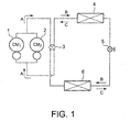
- Figure 1 illustrates a refrigerating cycle of an air conditioning apparatus to which the present invention is applied.
- the exhaust side of two compressors 1 and 2 is connected to one refrigerant pipe in a shared manner and the intake side thereof is also connected to one refrigerant pipe in a shared manner.
- the pipe of the exhaust side and the refrigerant pipe of the intake side are connected to an input and output of a four-way valve 3, respectively.
- refrigerant when heating operation is performed, as indicated by arrows A and B, refrigerant is circulated via a path from the compressors 1 and 2 to the four-way valve 3 to the indoor heat exchanger 4 to the expansion valve 5 to the outdoor heat exchanger 6 to the four-way valve 3 to the compressors 1 and 2.
- refrigerant is circulated via a path from the compressors 1 and 2 to the four-way valve 3 to the outdoor heat exchanger 6 to the expansion valve 5 to the indoor heat exchanger 4 to the four-way valve 3 to the compressors 1 and 2.
- Figure 2 is a circuit diagram illustrating a configuration of a control circuit performing capacity control of compressors 1 and 2 constituting the refrigerating cycle illustrated in Figure 1 by use of separate inverter circuits.
- an input end of an inrush control circuit 8 is connected to a commercial three-phase AC power source 7 of 400 V.
- the inrush control circuit 8 there is used, for example, one in which a resistor element and relay contact are connected in parallel; the relay contact is held at an OFF state at the time when the power source is turned on and thereafter, the relay contact is changed to an ON state, whereby inrush current is suppressed.
- a compound module 10 for driving the compressor 1 To an output end of the inrush control circuit 8, there are connected a compound module 10 for driving the compressor 1 and a compound module 20 for driving the compressor 2.
- the compound modules 10 and 20 are a combination of a rectifier circuit 11 and inverter circuit 12, and a combination of a rectifier circuit 21 and inverter circuit 22, respectively, and each constructed as one integrated package.
- the two modules are identical with each other, having an identical rating.
- the compressors 1 and 2 are also identical with each other, having an identical rating.
- Each input end of the rectifier circuits 11 and 21 is connected to the output end of the inrush control circuit 8.
- the air conditioning apparatus has an air conditioning capacity equivalent to 10 horsepower
- two compressors having a power of 5 horsepower are used as the compressors 1 and 2.
- the rectifier circuits 11 and 21 there are used rectifier circuits each having a diode of three-phase bridge connection so as to be capable of receiving alternating current having a voltage of 400 V and outputting direct current of 25 A;
- the inverter circuits 12 and 22 there are used inverter circuits having a switching element, such as IGBT, of three-phase bridge connection and having a rating exceeding a DC input current of 25 A and an input voltage of 600 V.
- Each output end of the rectifier circuits 11 and 21 is connected in parallel, forming a DC electric line; to the positive electric line (or negative electric line) of this DC electric line, there is connected in series a power factor improving reactor 31; between the positive and negative electric lines of the load side of this power factor improving reactor 31, there is connected a smoothing capacitor 32.
- the power source side of a filter circuit 33 preventing harmonics from leaking into the power source side.
- the load side of the filter circuit 33 is branched and connected to a DC input end of the inverter circuit 12 and to a DC input end of the inverter circuit 22.
- a current detection circuit 13 detecting an input current of the rectifier circuit 11
- a current detection circuit 23 detecting an input current of the rectifier circuit 21
- a control circuit 30 receiving an air conditioning load calculated in consideration of current detection values from the current detection circuits and of a difference between a set value of a temperature setting unit (not illustrated) and a temperature detection value from a room temperature sensor, and generating an ON/OFF signal of each switching element of the inverter circuits 12 and 22
- a drive circuit 14 amplifying the ON/OFF signal and supplying it to the inverter circuit 12
- a drive circuit 24 supplying it to the inverter circuit 22.
- Alternating current of the three-phase AC power source 7 is supplied via the inrush control circuit 8 to the rectifier circuits 11 and 21 and outputted as pulsating flow from the rectifier circuits.
- the pulsating flow is applied via the power factor improving reactor 31 to both ends of the smoothing capacitor 32 and converted into direct current having small ripple components by the capacitor 32.
- the direct current is supplied via the filter circuit 33 to the inverter circuits 12 and 22.
- control circuit 30 applies an ON/OFF signal to the inverter circuit 12 to drive the compressor 1 only, or applies an ON/OFF signal to both the inverter circuits 12 and 22 to drive both the compressors 1 and 2.
- the output frequency of the inverter circuit 12 is varied to vary the compressor capacity according to a variation in air conditioning load; when the air conditioning load is large and thus both the compressors 1 and 2 are driven, the respective output frequencies are varied to equalize the compressor capacity and rate of change between the compressors 1 and 2 according to a variation in air conditioning load.
- Figure 3 is a diagram illustrating the relationship described above.
- the capacity of the compressor is controlled so that air conditioning load and compressor capacity are substantially proportional to each other according to the line R in the whole variation range of air conditioning load.
- the current value of the compound modules 10 and 20 can be balanced when both the compressors operate.
- the compound modules 10 and 20 used have an identical rating, so the rectifier circuits 11 and 21 use a rectifier element having an identical current capacity.
- the output current may become unbalanced between the rectifier circuits 11 and 21.
- the current detection circuits 13 and 23 respectively, to perform control so that the total value of the two current detection values does not exceed a predetermined threshold value.
- the input current of the rectifier circuit 11 detected by the current detection circuit 13 is i 1
- the input current of the rectifier circuit 21 detected by the current detection circuit 23 is i 2
- the output frequency of the inverter circuit is controlled so that the total current I does not exceed the threshold value Is 1 , i.e., I ⁇ Is 1 .
- the output frequency of the inverter circuit is controlled so that a threshold value Is 2 (>Is 1 , generally 2 Is 1 ) is not exceeded, i.e., I ⁇ Is 2 .
- Figure 4 is a flowchart illustrating a specific processing procedure for suppressing, as described above, the input current to a value smaller than a threshold value.
- the number n of compressors operated and the output frequency of each inverter circuit are determined based on an air conditioning load of the indoor equipment.
- the determination of the number n of compressors operated and the output frequency of each inverter circuit has been variously proposed and known, and hence an explanation thereof is omitted.
- step 102 detection current values Is 1 and Is 2 are read.
- step 103 the total value I of the detection current values is calculated.
- step 104 it is determined whether or not the number of compressors operated is one; when it is determined that the number is one, it is determined in step 105 whether or not the total value I has exceeded a threshold value Is 1 for one compressor; when the total value I has exceeded Is 1 , the output frequency of the inverter circuit currently operating is reduced in step 106 and the above processing is repeated; when the total value I has not exceeded Is 1 , the above processing is repeated without reducing the frequency.
- step 104 when it is determined in step 104 that the number of compressors operated is not one, it is determined in step 107 that the total value I has exceeded a threshold value Is 2 for two compressors; when the total value I has exceeded Is 2 , the output frequency of the inverter circuit currently operating is reduced in step 106 and the above processing is repeated; when the total value I has not exceeded IS 2 , the above processing is repeated without reducing the frequency.
- the inverter circuits 12 and 22 are constructed as a constituent component of the compound modules 10 and 20 having integrated therein the rectifier circuits 11 and 21 rectifying alternating current, respectively; the AC power source 7 is connected to each input end of each of the rectifier circuits 11 and 21 of the compound modules 10 and 20; the output ends of the rectifier circuits 11 and 21 are connected in parallel to form a DC electric line; the DC electric line is connected to each input end of each of the inverter circuits 12 and 22 of the two compound modules 10 and 20.
- the power factor improving reactor 31 and the smoothing capacitors 32 and 33 is required. Accordingly, even when a plurality of compressors driven by respective inverter circuits is included, simplification of configuration and downsizing can be achieved.
- an air conditioning apparatus having two compressors driven by respective inverter circuits.
- the present invention is not limited thereto, and is also applicable to an air conditioning apparatus having three or more compressors driven by respective inverter circuits.
Landscapes
- Engineering & Computer Science (AREA)
- Power Engineering (AREA)
- Physics & Mathematics (AREA)
- Mechanical Engineering (AREA)
- Thermal Sciences (AREA)
- General Engineering & Computer Science (AREA)
- Air Conditioning Control Device (AREA)
- Inverter Devices (AREA)
- Control Of Multiple Motors (AREA)
- Rectifiers (AREA)
Abstract
When a plurality of compressors 1 and 2 are driven by respective inverter circuits, the inverter circuits 12 and 22 are constituted of a compound modules 10 and 20 having integrally incorporated therein rectifier circuits 11 and 21 rectifying alternating current, respectively, and an AC power source 7 is connected to each input end of each rectifier circuit of a plurality of the compound modules, and output ends of each rectifier circuit are connected in parallel to form a DC electric line, and the DC electric line is connected to input ends of each inverter circuit of the plurality of the compound modules.
Description
- The present invention relates to an air conditioning apparatus having a plurality of compressors driven by respective inverter circuits.
- There has heretofore been proposed an air conditioning apparatus having two capacity variable compressors driven and controlled by respective separate inverter circuits (for example, refer to
Japanese Patent No. 2557903 - The power source circuit driving the two compressors in such air conditioning apparatus includes one which rectifies alternating current from an AC power source by use of one rectifier circuit, converts an output of the rectifier circuit into alternating current of variable frequency by use of two inverter circuits and then supplies the respective alternating currents to the corresponding compressors, and one which rectifies alternating current from an AC power source by use of two rectifier circuits, converts respective outputs of the rectifier circuits into alternating current of variable frequency by use of inverter circuits and then supplies the respective alternating currents to the corresponding compressors.
- The AC power source driving the above described air conditioning apparatus includes a commercial three-phase AC power source of 200 V and a commercial three-phase AC power source of 400 V. Here, in the case of an air conditioning apparatus having an air conditioning capacity of 10 horsepower, the capacity of the two compressors is equivalent to 5 horsepower; for example, when the three-phase AC power source of 400 V drives a compressor of 5 horsepower, the input current in the AC power source side is approximately 11 A. Consequently, when two compressors are driven, the current in the AC power source side is 22 A.
- When alternating current from an AC power source is rectified by one rectifier circuit to obtain direct current for two compressors, the current flowing in the rectifier circuit is approximately 41 A, so the rectifier circuit used must have a rating of 50 A.
- However, the rectifier circuit having a rating of AC input voltage of 400 V and a rating of output current of 50 A is not common, being a special kind from a viewpoint of capacity, thus resulting in a large configuration and high cost.
- Meanwhile, as the inverter device controlling the capacity of a compressor, there is mostly used a compound module having a rectifier circuit and inverter circuit integrated as one package. In the compound module, the rectifier circuit acts as the DC power source of the inverter circuit incorporated integrally therewith, thus having a rating identical with that of the inverter circuit.
- Accordingly, when there is used the compound module which rectifies alternating current from an AC power source by use of one rectifier circuit to obtain DC power for two compressors, there must be used as the inverter circuit an element having a large rating capable of outputting AC power for two compressors. The element having such a large rating is expensive and has a large configuration, increasing the size of the air conditioning apparatus holding the element.
- Thus, without using any compound module, there can alternatively be used a configuration which separates a rectifier circuit and inverter circuit and makes semiconductor connection. In this case, however, it takes much labor to perform wiring and also, a wide installation space is required.
- Meanwhile, when a configuration is used in which the DC power of two inverter circuits is obtained from respective separate rectifier circuits, the rating of current of the rectifier circuit is identical with that of the inverter circuit, so a compound module can be used.
- In this configuration, however, between the rectifier circuit and inverter circuit, there must be arranged for each compound module, circuit elements such as a power factor improving reactor and a smoothing capacitor, and also a filter circuit, thus resulting in a large configuration and high cost.
- To solve the above problem, the present invention has been achieved. An object of the present invention is to provide an air conditioning apparatus capable of achieving simplification of configuration and downsizing even when a plurality of compressors driven by respective inverter circuits are included.
- To achieve the above object, according to the present invention, an air conditioning apparatus having a plurality of compressors driven by respective inverter circuits is characterized in that: the inverter circuit is constructed as a compound module in which the inverter circuit is incorporated integrally with a rectifier circuit rectifying alternating current; an AC power source is connected to each input end of each rectifier circuit of a plurality of the compound modules, and output ends of each rectifier circuit are connected in parallel to form a DC electric line, and the DC electric line is connected to input ends of each inverter circuit of the plurality of the compound modules.
- According to the above configuration, there can be provided the air conditioning apparatus capable of achieving simplification of configuration and downsizing even when provided with a plurality of compressors driven by respective inverter circuits.
-
- Figure 1 is a view illustrating a refrigerating cycle of an air conditioning apparatus to which the present invention is applied;
- Figure 2 is a circuit diagram illustrating a configuration of a control circuit performing capacity control of compressors constituting the refrigerating cycle illustrated in Figure 1 by use of separate inverter circuits;
- Figure 3 is a diagram for explaining a state in which the number of compressors operated and compressor capacity are controlled according to a variation in air conditioning load; and
- Figure 4 is a flowchart illustrating a specific processing procedure of the control circuit illustrated in Figure 2.
- Figure 1 illustrates a refrigerating cycle of an air conditioning apparatus to which the present invention is applied. In Figure 1, the exhaust side of two
compressors way valve 3, respectively. Between one switching port and the other switching port of the four-way valve 3, there are sequentially connected via the refrigerant pipe anindoor heat exchanger 4, anexpansion valve 5 and anoutdoor heat exchanger 6. - Accordingly, when heating operation is performed, as indicated by arrows A and B, refrigerant is circulated via a path from the
compressors way valve 3 to theindoor heat exchanger 4 to theexpansion valve 5 to theoutdoor heat exchanger 6 to the four-way valve 3 to thecompressors compressors way valve 3 to theoutdoor heat exchanger 6 to theexpansion valve 5 to theindoor heat exchanger 4 to the four-way valve 3 to thecompressors - Figure 2 is a circuit diagram illustrating a configuration of a control circuit performing capacity control of
compressors inrush control circuit 8 is connected to a commercial three-phaseAC power source 7 of 400 V. - As the
inrush control circuit 8, there is used, for example, one in which a resistor element and relay contact are connected in parallel; the relay contact is held at an OFF state at the time when the power source is turned on and thereafter, the relay contact is changed to an ON state, whereby inrush current is suppressed. - To an output end of the
inrush control circuit 8, there are connected acompound module 10 for driving thecompressor 1 and acompound module 20 for driving thecompressor 2. Thecompound modules rectifier circuit 11 andinverter circuit 12, and a combination of arectifier circuit 21 andinverter circuit 22, respectively, and each constructed as one integrated package. The two modules are identical with each other, having an identical rating. Thecompressors rectifier circuits inrush control circuit 8. - Here, when it is assumed that the air conditioning apparatus has an air conditioning capacity equivalent to 10 horsepower, two compressors having a power of 5 horsepower are used as the
compressors compressors rectifier circuits inverter circuits - Each output end of the
rectifier circuits factor improving reactor 31; between the positive and negative electric lines of the load side of this powerfactor improving reactor 31, there is connected asmoothing capacitor 32. - Also, to the positive and negative electric lines, there is connected the power source side of a
filter circuit 33 preventing harmonics from leaking into the power source side. The load side of thefilter circuit 33 is branched and connected to a DC input end of theinverter circuit 12 and to a DC input end of theinverter circuit 22. To an AC output end of theinverter circuit 12 and an AC output end of theinverter circuit 22, there are connected thecompressor 1 andcompressor 2, respectively. - Meanwhile, in order to control the
inverter circuits current detection circuit 13 detecting an input current of therectifier circuit 11; acurrent detection circuit 23 detecting an input current of therectifier circuit 21; acontrol circuit 30 receiving an air conditioning load calculated in consideration of current detection values from the current detection circuits and of a difference between a set value of a temperature setting unit (not illustrated) and a temperature detection value from a room temperature sensor, and generating an ON/OFF signal of each switching element of theinverter circuits drive circuit 14 amplifying the ON/OFF signal and supplying it to theinverter circuit 12; and a drive circuit 24 supplying it to theinverter circuit 22. - The operation in the first embodiment configured as described above will be described with reference to Figures 2 and 3. Alternating current of the three-phase
AC power source 7 is supplied via theinrush control circuit 8 to therectifier circuits - The pulsating flow is applied via the power
factor improving reactor 31 to both ends of thesmoothing capacitor 32 and converted into direct current having small ripple components by thecapacitor 32. The direct current is supplied via thefilter circuit 33 to theinverter circuits - According to an air conditioning load, the
control circuit 30 applies an ON/OFF signal to theinverter circuit 12 to drive thecompressor 1 only, or applies an ON/OFF signal to both theinverter circuits compressors - Here, when the air conditioning load is small and thus only the
compressor 1 is driven, the output frequency of theinverter circuit 12 is varied to vary the compressor capacity according to a variation in air conditioning load; when the air conditioning load is large and thus both thecompressors compressors - Figure 3 is a diagram illustrating the relationship described above. The capacity of the compressor is controlled so that air conditioning load and compressor capacity are substantially proportional to each other according to the line R in the whole variation range of air conditioning load. However, in a range in which the air conditioning load is smaller than Q1, the capacity of the first compressor is controlled to have a value of R1 or less; in a range in which the air conditioning load is larger than Q1, both the first compressor and second compressor are controlled by substantially the same frequency, whereby the capacity of the compressors is controlled in a range from R1 to R2 (= 2R1), and even when the air conditioning load exceeds Q2, the capacity of the compressors is held at R2.
- As a result of performing such control, the current value of the
compound modules - According to the first embodiment, the
compound modules rectifier circuits rectifier circuits - Consequently, even when an input current of one of the
compound modules - Thus, according to the first embodiment, in the input side of the
rectifier circuits current detection circuits - More specifically, assume that the input current of the
rectifier circuit 11 detected by thecurrent detection circuit 13 is i1, and the input current of therectifier circuit 21 detected by thecurrent detection circuit 23 is i2. Thecontrol circuit 30 reads these current detection values and calculates the total current I = i1 + i2, and controls the output frequency of theinverter circuits - Specifically, in a state where only one compressor operates, using a threshold value Is1, the output frequency of the inverter circuit is controlled so that the total current I does not exceed the threshold value Is1, i.e., I ≤ Is1.
- On the other hand, in a state where the two compressors operate, the output frequency of the inverter circuit is controlled so that a threshold value Is2 (>Is1, generally 2 Is1) is not exceeded, i.e., I ≤ Is2.
- Figure 4 is a flowchart illustrating a specific processing procedure for suppressing, as described above, the input current to a value smaller than a threshold value. Here, in
step 101, the number n of compressors operated and the output frequency of each inverter circuit are determined based on an air conditioning load of the indoor equipment. The determination of the number n of compressors operated and the output frequency of each inverter circuit has been variously proposed and known, and hence an explanation thereof is omitted. - Thereafter, in
step 102, detection current values Is1 and Is2 are read. Instep 103, the total value I of the detection current values is calculated. Then, instep 104, it is determined whether or not the number of compressors operated is one; when it is determined that the number is one, it is determined instep 105 whether or not the total value I has exceeded a threshold value Is1 for one compressor; when the total value I has exceeded Is1, the output frequency of the inverter circuit currently operating is reduced instep 106 and the above processing is repeated; when the total value I has not exceeded Is1, the above processing is repeated without reducing the frequency. - Meanwhile, when it is determined in
step 104 that the number of compressors operated is not one, it is determined instep 107 that the total value I has exceeded a threshold value Is2 for two compressors; when the total value I has exceeded Is2, the output frequency of the inverter circuit currently operating is reduced instep 106 and the above processing is repeated; when the total value I has not exceeded IS2, the above processing is repeated without reducing the frequency. - As described above, according to the first embodiment, the
inverter circuits compound modules rectifier circuits AC power source 7 is connected to each input end of each of therectifier circuits compound modules rectifier circuits inverter circuits compound modules factor improving reactor 31 and the smoothingcapacitors - In the first embodiment, there is described an air conditioning apparatus having two compressors driven by respective inverter circuits. However, the present invention is not limited thereto, and is also applicable to an air conditioning apparatus having three or more compressors driven by respective inverter circuits.
Claims (2)
- An air conditioning apparatus having a plurality of compressors driven by respective inverter circuits, the apparatus characterized in that:said inverter circuit is constructed as a compound module in which the inverter circuit is incorporated integrally with a rectifier circuit rectifying alternating current; andan AC power source is connected to each input end of each rectifier circuit of a plurality of said compound modules, and output ends of each rectifier circuit are connected in parallel to form a DC electric line, and the DC electric line is connected to input ends of each inverter circuit of the plurality of said compound modules.
- The air conditioning apparatus according to claim 1, characterized by comprising:a current detection circuit detecting an input current of each rectifier circuit of a plurality of said compound modules; andcurrent control means for controlling, during operating of the inverter circuits of the plurality of said compound modules, an output frequency of each inverter circuit of said compound modules based on a result of comparing a total value of the current detected by said current detection circuit with a current set value set to a different value according to the number of said inverter circuits currently operating.
Applications Claiming Priority (2)
| Application Number | Priority Date | Filing Date | Title |
|---|---|---|---|
| JP2004182626 | 2004-06-21 | ||
| PCT/JP2005/009867 WO2005124988A1 (en) | 2004-06-21 | 2005-05-30 | Air conditioner |
Publications (3)
| Publication Number | Publication Date |
|---|---|
| EP1796255A1 true EP1796255A1 (en) | 2007-06-13 |
| EP1796255A4 EP1796255A4 (en) | 2008-05-28 |
| EP1796255B1 EP1796255B1 (en) | 2016-02-17 |
Family
ID=35510053
Family Applications (1)
| Application Number | Title | Priority Date | Filing Date |
|---|---|---|---|
| EP05743295.7A Expired - Lifetime EP1796255B1 (en) | 2004-06-21 | 2005-05-30 | Air conditioner |
Country Status (5)
| Country | Link |
|---|---|
| EP (1) | EP1796255B1 (en) |
| JP (1) | JPWO2005124988A1 (en) |
| CN (1) | CN1969450B (en) |
| BR (1) | BRPI0512085A (en) |
| WO (1) | WO2005124988A1 (en) |
Cited By (3)
| Publication number | Priority date | Publication date | Assignee | Title |
|---|---|---|---|---|
| EP2045548A1 (en) * | 2007-10-05 | 2009-04-08 | Frigo System S.p.A. | Refrigerating unit |
| US9683772B2 (en) | 2009-09-16 | 2017-06-20 | Daikin Industries, Ltd. | Container refrigeration system |
| EP3816538A1 (en) * | 2019-11-01 | 2021-05-05 | Panasonic Intellectual Property Management Co., Ltd. | Air conditioning device |
Families Citing this family (9)
| Publication number | Priority date | Publication date | Assignee | Title |
|---|---|---|---|---|
| AU2006335684C1 (en) * | 2006-03-15 | 2009-12-10 | Mitsubishi Electric Corporation | Electric motor driving device and compressor driving device |
| JP5316456B2 (en) * | 2010-03-25 | 2013-10-16 | ダイキン工業株式会社 | Air conditioner |
| JP5316457B2 (en) * | 2010-03-25 | 2013-10-16 | ダイキン工業株式会社 | Air conditioner |
| JP6048736B2 (en) * | 2012-11-29 | 2016-12-21 | 株式会社ノーリツ | Water heater |
| JP6407519B2 (en) * | 2013-11-19 | 2018-10-17 | 東芝ライフスタイル株式会社 | Air conditioner |
| KR101720496B1 (en) * | 2015-08-27 | 2017-04-10 | 엘지전자 주식회사 | Power converting apparatus and air conditioner including the same |
| CN105546762A (en) * | 2016-01-19 | 2016-05-04 | 珠海格力电器股份有限公司 | Variable frequency air conditioner and control method thereof |
| CN111656678B (en) * | 2018-02-06 | 2023-05-02 | 三菱电机株式会社 | Variable frequency control device |
| US12244245B2 (en) | 2021-10-18 | 2025-03-04 | Carrier Corporation | Transport refrigeration system with paralleled inverters |
Family Cites Families (16)
| Publication number | Priority date | Publication date | Assignee | Title |
|---|---|---|---|---|
| JPS61262082A (en) * | 1985-05-16 | 1986-11-20 | Yokogawa Electric Corp | Regulated power source |
| JP2557903B2 (en) * | 1987-09-10 | 1996-11-27 | 株式会社東芝 | Air conditioner |
| GB2215866B (en) * | 1988-02-09 | 1992-06-24 | Toshiba Kk | Multi-type air conditioner system with oil level control for parallel operated compressor therein |
| JPH0591751A (en) * | 1991-06-06 | 1993-04-09 | Honda Motor Co Ltd | Portable AC power supply |
| JPH0686567A (en) * | 1992-09-02 | 1994-03-25 | Toshiba Corp | Power conversion apparatus |
| JP2833460B2 (en) * | 1993-12-27 | 1998-12-09 | 株式会社日立製作所 | Power system |
| JP3283134B2 (en) * | 1994-03-04 | 2002-05-20 | 株式会社東芝 | PWM converter device |
| JPH0937554A (en) * | 1995-07-21 | 1997-02-07 | Meidensha Corp | Control device of pwm converter and uninterruptible power supply device using the control device |
| JP3609514B2 (en) * | 1995-11-16 | 2005-01-12 | 三洋電機株式会社 | Inverter control device |
| WO1998010508A1 (en) * | 1996-09-06 | 1998-03-12 | Hitachi, Ltd. | Semiconductor device |
| JP2000316294A (en) * | 1999-04-27 | 2000-11-14 | Hitachi Ltd | DC brushless motor driving device and air conditioner using the same |
| JP2002112550A (en) * | 2000-09-29 | 2002-04-12 | Matsushita Electric Ind Co Ltd | Air conditioner power supply |
| JP3419448B2 (en) * | 2000-12-25 | 2003-06-23 | サンケン電気株式会社 | Three-phase AC-DC converter |
| JP4251776B2 (en) * | 2001-02-13 | 2009-04-08 | 株式会社日立産機システム | Inverter device |
| WO2002103877A2 (en) * | 2001-06-20 | 2002-12-27 | Peck Seng Ong | Optimized power supply system using two vfd with their dc bus in parallel |
| JP4007063B2 (en) * | 2002-05-22 | 2007-11-14 | 富士電機システムズ株式会社 | Parallel control apparatus and parallel control method for inverter |
-
2005
- 2005-05-30 WO PCT/JP2005/009867 patent/WO2005124988A1/en not_active Ceased
- 2005-05-30 JP JP2006514682A patent/JPWO2005124988A1/en active Pending
- 2005-05-30 BR BRPI0512085-3A patent/BRPI0512085A/en not_active IP Right Cessation
- 2005-05-30 EP EP05743295.7A patent/EP1796255B1/en not_active Expired - Lifetime
- 2005-05-30 CN CN2005800202089A patent/CN1969450B/en not_active Expired - Fee Related
Cited By (3)
| Publication number | Priority date | Publication date | Assignee | Title |
|---|---|---|---|---|
| EP2045548A1 (en) * | 2007-10-05 | 2009-04-08 | Frigo System S.p.A. | Refrigerating unit |
| US9683772B2 (en) | 2009-09-16 | 2017-06-20 | Daikin Industries, Ltd. | Container refrigeration system |
| EP3816538A1 (en) * | 2019-11-01 | 2021-05-05 | Panasonic Intellectual Property Management Co., Ltd. | Air conditioning device |
Also Published As
| Publication number | Publication date |
|---|---|
| CN1969450B (en) | 2010-05-12 |
| JPWO2005124988A1 (en) | 2008-04-17 |
| CN1969450A (en) | 2007-05-23 |
| WO2005124988A1 (en) | 2005-12-29 |
| EP1796255B1 (en) | 2016-02-17 |
| BRPI0512085A (en) | 2008-02-06 |
| EP1796255A4 (en) | 2008-05-28 |
Similar Documents
| Publication | Publication Date | Title |
|---|---|---|
| EP2072923B1 (en) | Motor controller of air conditioner | |
| EP0652634B1 (en) | Air conditioning apparatus usable for wide-range source voltage | |
| CN105594111B (en) | Power conversion device and air-conditioning device | |
| US8164292B2 (en) | Motor controller of air conditioner | |
| EP2779406B1 (en) | Power converter and air conditioner having the same | |
| JP3472522B2 (en) | Multiple motor control device, power conversion device, inverter module, converter module | |
| EP1796255B1 (en) | Air conditioner | |
| KR20130026449A (en) | Variable speed drive | |
| EP3133728A1 (en) | Power conversion apparatus and air conditioner including the same | |
| JP2004364491A (en) | Power supply system and air conditioner | |
| KR20140112297A (en) | Power converter and air conditioner including the same | |
| KR20170004487A (en) | Power converting apparatus and air conditioner including the same | |
| US10928112B2 (en) | Heat pump device | |
| CN111868448A (en) | Adaptive logic board for variable speed drive | |
| JP6146316B2 (en) | Air conditioner | |
| KR100832945B1 (en) | Air conditioner | |
| WO2018142738A1 (en) | Air conditioner | |
| KR102201579B1 (en) | Motor Driving Apparatus and Air conditioner | |
| EP2980973B1 (en) | Backflow prevention device, power conversion device, and cooling air-conditioning device | |
| US12525894B2 (en) | AC/DC converter, electric motor drive device and refrigeration cycle device | |
| JP2005223978A (en) | Motor drive device | |
| KR20110003089A (en) | Motor control device of air conditioner using distributed power supply | |
| KR102260614B1 (en) | Air conditioner | |
| KR20190096725A (en) | Power converting apparatus and air conditioner including the same | |
| JP2007244170A (en) | Power supply |
Legal Events
| Date | Code | Title | Description |
|---|---|---|---|
| PUAI | Public reference made under article 153(3) epc to a published international application that has entered the european phase |
Free format text: ORIGINAL CODE: 0009012 |
|
| 17P | Request for examination filed |
Effective date: 20061215 |
|
| AK | Designated contracting states |
Kind code of ref document: A1 Designated state(s): DE FR IT |
|
| RIN1 | Information on inventor provided before grant (corrected) |
Inventor name: KOIZUMI, TETSUYA Inventor name: KOBAYASHI, TAKEHIRO |
|
| DAX | Request for extension of the european patent (deleted) | ||
| RBV | Designated contracting states (corrected) |
Designated state(s): DE FR IT |
|
| A4 | Supplementary search report drawn up and despatched |
Effective date: 20080502 |
|
| RIC1 | Information provided on ipc code assigned before grant |
Ipc: H02M 5/458 20060101AFI20080424BHEP Ipc: F25B 49/02 20060101ALI20060113BHEP Ipc: F25B 1/00 20060101ALI20060113BHEP |
|
| 17Q | First examination report despatched |
Effective date: 20090422 |
|
| GRAP | Despatch of communication of intention to grant a patent |
Free format text: ORIGINAL CODE: EPIDOSNIGR1 |
|
| INTG | Intention to grant announced |
Effective date: 20150724 |
|
| GRAS | Grant fee paid |
Free format text: ORIGINAL CODE: EPIDOSNIGR3 |
|
| GRAA | (expected) grant |
Free format text: ORIGINAL CODE: 0009210 |
|
| AK | Designated contracting states |
Kind code of ref document: B1 Designated state(s): DE FR IT |
|
| REG | Reference to a national code |
Ref country code: DE Ref legal event code: R096 Ref document number: 602005048464 Country of ref document: DE |
|
| REG | Reference to a national code |
Ref country code: FR Ref legal event code: PLFP Year of fee payment: 12 |
|
| REG | Reference to a national code |
Ref country code: DE Ref legal event code: R097 Ref document number: 602005048464 Country of ref document: DE |
|
| PLBE | No opposition filed within time limit |
Free format text: ORIGINAL CODE: 0009261 |
|
| STAA | Information on the status of an ep patent application or granted ep patent |
Free format text: STATUS: NO OPPOSITION FILED WITHIN TIME LIMIT |
|
| 26N | No opposition filed |
Effective date: 20161118 |
|
| REG | Reference to a national code |
Ref country code: FR Ref legal event code: PLFP Year of fee payment: 13 |
|
| REG | Reference to a national code |
Ref country code: FR Ref legal event code: PLFP Year of fee payment: 14 |
|
| REG | Reference to a national code |
Ref country code: FR Ref legal event code: PLFP Year of fee payment: 19 |
|
| PGFP | Annual fee paid to national office [announced via postgrant information from national office to epo] |
Ref country code: FR Payment date: 20240328 Year of fee payment: 20 |
|
| PGFP | Annual fee paid to national office [announced via postgrant information from national office to epo] |
Ref country code: DE Payment date: 20240328 Year of fee payment: 20 |
|
| PGFP | Annual fee paid to national office [announced via postgrant information from national office to epo] |
Ref country code: IT Payment date: 20240411 Year of fee payment: 20 |
|
| REG | Reference to a national code |
Ref country code: DE Ref legal event code: R071 Ref document number: 602005048464 Country of ref document: DE |