EP1795834A2 - Vapor compression refrigerating system - Google Patents
Vapor compression refrigerating system Download PDFInfo
- Publication number
- EP1795834A2 EP1795834A2 EP06125365A EP06125365A EP1795834A2 EP 1795834 A2 EP1795834 A2 EP 1795834A2 EP 06125365 A EP06125365 A EP 06125365A EP 06125365 A EP06125365 A EP 06125365A EP 1795834 A2 EP1795834 A2 EP 1795834A2
- Authority
- EP
- European Patent Office
- Prior art keywords
- refrigerant
- pressure
- reducing
- vapor compression
- refrigerating system
- Prior art date
- Legal status (The legal status is an assumption and is not a legal conclusion. Google has not performed a legal analysis and makes no representation as to the accuracy of the status listed.)
- Withdrawn
Links
Images



Classifications
-
- F—MECHANICAL ENGINEERING; LIGHTING; HEATING; WEAPONS; BLASTING
- F25—REFRIGERATION OR COOLING; COMBINED HEATING AND REFRIGERATION SYSTEMS; HEAT PUMP SYSTEMS; MANUFACTURE OR STORAGE OF ICE; LIQUEFACTION SOLIDIFICATION OF GASES
- F25B—REFRIGERATION MACHINES, PLANTS OR SYSTEMS; COMBINED HEATING AND REFRIGERATION SYSTEMS; HEAT PUMP SYSTEMS
- F25B9/00—Compression machines, plants or systems, in which the refrigerant is air or other gas of low boiling point
- F25B9/002—Compression machines, plants or systems, in which the refrigerant is air or other gas of low boiling point characterised by the refrigerant
- F25B9/008—Compression machines, plants or systems, in which the refrigerant is air or other gas of low boiling point characterised by the refrigerant the refrigerant being carbon dioxide
-
- F—MECHANICAL ENGINEERING; LIGHTING; HEATING; WEAPONS; BLASTING
- F25—REFRIGERATION OR COOLING; COMBINED HEATING AND REFRIGERATION SYSTEMS; HEAT PUMP SYSTEMS; MANUFACTURE OR STORAGE OF ICE; LIQUEFACTION SOLIDIFICATION OF GASES
- F25B—REFRIGERATION MACHINES, PLANTS OR SYSTEMS; COMBINED HEATING AND REFRIGERATION SYSTEMS; HEAT PUMP SYSTEMS
- F25B40/00—Subcoolers, desuperheaters or superheaters
-
- F—MECHANICAL ENGINEERING; LIGHTING; HEATING; WEAPONS; BLASTING
- F25—REFRIGERATION OR COOLING; COMBINED HEATING AND REFRIGERATION SYSTEMS; HEAT PUMP SYSTEMS; MANUFACTURE OR STORAGE OF ICE; LIQUEFACTION SOLIDIFICATION OF GASES
- F25B—REFRIGERATION MACHINES, PLANTS OR SYSTEMS; COMBINED HEATING AND REFRIGERATION SYSTEMS; HEAT PUMP SYSTEMS
- F25B43/00—Arrangements for separating or purifying gases or liquids; Arrangements for vaporising the residuum of liquid refrigerant, e.g. by heat
- F25B43/006—Accumulators
-
- F—MECHANICAL ENGINEERING; LIGHTING; HEATING; WEAPONS; BLASTING
- F25—REFRIGERATION OR COOLING; COMBINED HEATING AND REFRIGERATION SYSTEMS; HEAT PUMP SYSTEMS; MANUFACTURE OR STORAGE OF ICE; LIQUEFACTION SOLIDIFICATION OF GASES
- F25B—REFRIGERATION MACHINES, PLANTS OR SYSTEMS; COMBINED HEATING AND REFRIGERATION SYSTEMS; HEAT PUMP SYSTEMS
- F25B2309/00—Gas cycle refrigeration machines
- F25B2309/06—Compression machines, plants or systems characterised by the refrigerant being carbon dioxide
- F25B2309/061—Compression machines, plants or systems characterised by the refrigerant being carbon dioxide with cycle highest pressure above the supercritical pressure
-
- F—MECHANICAL ENGINEERING; LIGHTING; HEATING; WEAPONS; BLASTING
- F25—REFRIGERATION OR COOLING; COMBINED HEATING AND REFRIGERATION SYSTEMS; HEAT PUMP SYSTEMS; MANUFACTURE OR STORAGE OF ICE; LIQUEFACTION SOLIDIFICATION OF GASES
- F25B—REFRIGERATION MACHINES, PLANTS OR SYSTEMS; COMBINED HEATING AND REFRIGERATION SYSTEMS; HEAT PUMP SYSTEMS
- F25B2400/00—Component parts or details not otherwise provided for in this subclass
- F25B2400/05—Compression system with heat exchange between particular parts of the system
- F25B2400/051—Compression system with heat exchange between particular parts of the system between the accumulator and another part of the cycle
-
- F—MECHANICAL ENGINEERING; LIGHTING; HEATING; WEAPONS; BLASTING
- F25—REFRIGERATION OR COOLING; COMBINED HEATING AND REFRIGERATION SYSTEMS; HEAT PUMP SYSTEMS; MANUFACTURE OR STORAGE OF ICE; LIQUEFACTION SOLIDIFICATION OF GASES
- F25B—REFRIGERATION MACHINES, PLANTS OR SYSTEMS; COMBINED HEATING AND REFRIGERATION SYSTEMS; HEAT PUMP SYSTEMS
- F25B2400/00—Component parts or details not otherwise provided for in this subclass
- F25B2400/05—Compression system with heat exchange between particular parts of the system
- F25B2400/053—Compression system with heat exchange between particular parts of the system between the storage receiver and another part of the system
-
- F—MECHANICAL ENGINEERING; LIGHTING; HEATING; WEAPONS; BLASTING
- F25—REFRIGERATION OR COOLING; COMBINED HEATING AND REFRIGERATION SYSTEMS; HEAT PUMP SYSTEMS; MANUFACTURE OR STORAGE OF ICE; LIQUEFACTION SOLIDIFICATION OF GASES
- F25B—REFRIGERATION MACHINES, PLANTS OR SYSTEMS; COMBINED HEATING AND REFRIGERATION SYSTEMS; HEAT PUMP SYSTEMS
- F25B2400/00—Component parts or details not otherwise provided for in this subclass
- F25B2400/13—Economisers
-
- F—MECHANICAL ENGINEERING; LIGHTING; HEATING; WEAPONS; BLASTING
- F25—REFRIGERATION OR COOLING; COMBINED HEATING AND REFRIGERATION SYSTEMS; HEAT PUMP SYSTEMS; MANUFACTURE OR STORAGE OF ICE; LIQUEFACTION SOLIDIFICATION OF GASES
- F25B—REFRIGERATION MACHINES, PLANTS OR SYSTEMS; COMBINED HEATING AND REFRIGERATION SYSTEMS; HEAT PUMP SYSTEMS
- F25B2400/00—Component parts or details not otherwise provided for in this subclass
- F25B2400/23—Separators
-
- F—MECHANICAL ENGINEERING; LIGHTING; HEATING; WEAPONS; BLASTING
- F25—REFRIGERATION OR COOLING; COMBINED HEATING AND REFRIGERATION SYSTEMS; HEAT PUMP SYSTEMS; MANUFACTURE OR STORAGE OF ICE; LIQUEFACTION SOLIDIFICATION OF GASES
- F25B—REFRIGERATION MACHINES, PLANTS OR SYSTEMS; COMBINED HEATING AND REFRIGERATION SYSTEMS; HEAT PUMP SYSTEMS
- F25B2500/00—Problems to be solved
- F25B2500/18—Optimization, e.g. high integration of refrigeration components
-
- F—MECHANICAL ENGINEERING; LIGHTING; HEATING; WEAPONS; BLASTING
- F25—REFRIGERATION OR COOLING; COMBINED HEATING AND REFRIGERATION SYSTEMS; HEAT PUMP SYSTEMS; MANUFACTURE OR STORAGE OF ICE; LIQUEFACTION SOLIDIFICATION OF GASES
- F25B—REFRIGERATION MACHINES, PLANTS OR SYSTEMS; COMBINED HEATING AND REFRIGERATION SYSTEMS; HEAT PUMP SYSTEMS
- F25B41/00—Fluid-circulation arrangements
- F25B41/30—Expansion means; Dispositions thereof
- F25B41/39—Dispositions with two or more expansion means arranged in series, i.e. multi-stage expansion, on a refrigerant line leading to the same evaporator
Definitions
- the present invention relates to vapor compression refrigerating systems, and specifically, to vapor compression refrigerating systems using carbon dioxide refrigerant suitable for use in an air conditioning system for vehicles.
- a higher pressure-side pressure realizes an optimum coefficient of performance of the refrigerating system, is calculated by referring to a temperature of refrigerant in the higher pressure side and the like, and the valve opening degree of the expansion device is controlled, so that the higher pressure-side pressure is optimized.
- a structure is disclosed, for example, in Japanese Patent Application No. H11-193967 A , wherein an internal heat exchanger is provided for exchanging heat between refrigerant at an exit side of a radiator and refrigerant at a suction side of a compressor.
- an internal heat exchanger is provided for exchanging heat between refrigerant at an exit side of a radiator and refrigerant at a suction side of a compressor.
- refrigerant at an exit side of a radiator exchanges heat with refrigerant at a suction side of a compressor.
- refrigerant at a certain temperature for example, critical temperature of carbon dioxide
- the refrigerant at the exit to the radiator may not condense and may remain at a supercritical condition. If the refrigerant pressure is reduced, and if the refrigerant is evaporated by an evaporator, the refrigerating capacity may be reduced significantly.
- the refrigerating capacity may be increased or maintained, the higher pressure-side pressure may be reduced as compared with that of a refrigerating system having no internal heat exchanger, and the coefficient of performance of the refrigerating cycle may be increased.
- vapor compression refrigerating systems in particular, vapor compression refrigerating systems using carbon dioxide refrigerant, which may reduce the degree of superheating of the refrigerant at a suction side of a compressor, and which may increase a coefficient of performance of the refrigerating system.
- a vapor compression refrigerating system may operate at a supercritical condition, and has a compressor for compressing refrigerant; a radiator for reducing the temperature of refrigerant with an elevated temperature and an elevated pressure due to compression by the compressor, a first pressure-reducing means for reducing a pressure of refrigerant, the temperature of which is reduced by the radiator; a refrigerant branching means for dividing refrigerant (m) reduced in pressure by the first pressure-reducing means into a plurality of portions, a second pressure-reducing means for reducing a pressure of one portion of the refrigerant (m1) divided by the refrigerant branching means; and a third pressure-reducing means for reducing a pressure of another portion of the refrigerant (m2) divided by the refrigerant branching means, wherein the temperature of refrigerant compressed by the compressor is reduced by the radiator, the refrigerant passed through the radiator is reduced in pressure by the first pressure-reducing means.
- the pressure reduced refrigerant (m) is divided by the refrigerant branching means into portions, one portion of the refrigerant (m1) is reduced in pressure by the second pressure-reducing means.
- the pressure reduced refrigerant (m1') exchanges heat with refrigerant present between the first pressure-reducing means and the third pressure-reducing means by a cooler.
- Another portion of the refrigerant (m2) is reduced in pressure by the third pressure-reducing means.
- the pressure reduced refrigerant (m2') is evaporated by an evaporator, and the evaporated refrigerant (m2") and the refrigerant (m1') having passed through the cooler are mixed by an accumulator a gas/liquid separator provided for separating refrigerant gas and liquid refrigerant, and the mixed refrigerant is introduced into the compressor ( i.e. , a first vapor compression refrigerating system).
- a structure may be employed wherein the temperature of refrigerant compressed by the compressor is reduced by the radiator, the pressure of refrigerant passed through the radiator is reduced by the first pressure-reducing means, the pressure reduced refrigerant (m) is divided by the refrigerant branching means into a plurality of portions, one portion of refrigerant (m1) is reduced in pressure by the second pressure-reducing means, and the pressure reduced refrigerant (m1') exchanges heat with refrigerant (m) reduced in pressure by the first pressure-reducing means and before being divided by the refrigerant branching means by the cooler, thereby reducing the temperature of the refrigerant (m) reduced in pressure by the first pressure-reducing means.
- refrigerant (m2) is reduced in pressure by the third pressure-reducing means, the pressure reduced refrigerant (m2') is evaporated by the evaporator, the evaporated refrigerant (m2'') and the refrigerant (m1') having passed through the cooler are mixed by the gas/liquid separator ( e.g. , the accumulator), and the mixed refrigerant is introduced into the compressor.
- the gas/liquid separator e.g. , the accumulator
- the mixed refrigerant is introduced into the compressor.
- a structure may be employed wherein the second pressure-reducing means, the third pressure-reducing means, and the refrigerant branching means are assembled integrally.
- a structure also may be employed wherein the temperature of refrigerant compressed by the compressor is reduced by the radiator, the refrigerant passed through radiator is reduced in pressure by the first pressure-reducing means, and the pressure reduced refrigerant (m) is divided by the refrigerant branching means into a plurality of portions, one portion of refrigerant (m1) is reduced in pressure by the second pressure-reducing means, and the pressure reduced refrigerant (m1') exchanges heat with another portion of refrigerant (m2) divided by the refrigerant branching means by the cooler, thereby reducing the temperature of refrigerant (m2).
- the refrigerant (m2) passed through the cooler is reduced in pressure by the third pressure-reducing means, the pressure reduced refrigerant (m2') is evaporated by the evaporator, the evaporated refrigerant (m2'') and the refrigerant (m1') having passed through the cooler are mixed by the gas/liquid separator (e.g. , the accumulator), and the mixed refrigerant is introduced into the compressor.
- the gas/liquid separator e.g. , the accumulator
- the mixed refrigerant is introduced into the compressor.
- a structure may be employed wherein the first pressure-reducing means, the second pressure-reducing means and the refrigerant branching means are assembled integrally.
- a structure may be employed wherein the first pressure-reducing means is configured to adjust a degree of pressure reduction, and the degree of pressure reduction is adjusted by a pressure or a temperature, or both, of refrigerant flowing into the first pressure-reducing means.
- the second pressure-reducing means is configured to adjust a degree of pressure reduction, and the degree of pressure reduction is adjusted by a pressure or a temperature, or both, of refrigerant flowing into the second pressure-reducing means.
- a structure may be employed wherein the third pressure-reducing means is configured to adjust a degree of pressure reduction, and the degree of pressure reduction is adjusted by a pressure or a temperature, or both of refrigerant flowing into the third pressure-reducing means. Further, a structure may be employed wherein a degree of pressure reduction of the second pressure-reducing means and a degree of pressure reduction of the third pressure-reducing means are adjusted at a same rate.
- a structure may be employed wherein an outside air temperature detecting means for detecting a physical value having a correlation with an outside air temperature is provided, and when the physical value having a correlation with an outside air temperature detected by the outside air temperature detecting means is equal to or less than a predetermined value, the second pressure-reducing means is closed.
- a structure may be employed wherein an outside air temperature detecting means for detecting a physical value having a correlation with an outside air temperature is provided, and when the physical value having a correlation with an outside air temperature detected by the outside air temperature detecting means is equal to or less than a predetermined value, the refrigerant branching means prevents the flow of refrigerant into the cooler.
- a structure may be employed wherein a higher pressure detecting means for detecting a physical value having a correlation with a refrigerant pressure at a higher-pressure side in the refrigerating system from the compressor to the first pressure-reducing means is provided, and when the physical value having a correlation with a refrigerant pressure at the higher-pressure side detected by the higher pressure detecting means is equal to or less than a predetermined value, the second pressure-reducing means is closed.
- a structure may be employed wherein a higher pressure detecting means for detecting a physical value having a correlation with a refrigerant pressure at a high-pressure side in the refrigerating cycle from the compressor to the first pressure-reducing means is provided, and when the physical value having a correlation with a refrigerant pressure at the high-pressure side detected by the high pressure detecting means is equal to or less than a predetermined value, the refrigerant branching means stops directing refrigerant into the cooler.
- a vapor compression refrigerating system may operate at a supercritical condition and comprises a compressor for compressing refrigerant, a radiator for reducing the temperature of refrigerant with an elevated temperature and an elevated pressure compressed by the compressor, a first pressure-reducing means for reducing a pressure of refrigerant having been passed through the radiator, a second pressure-reducing means for further reducing a pressure of refrigerant (m) reduced in pressure by the first pressure-reducing means, and a refrigerant branching means for dividing the pressure reduced refrigerant.
- the temperature of refrigerant compressed by the compressor is reduced by the radiator, the refrigerant passed through the radiator is reduced in pressure by the first pressure-reducing means, the pressure reduced refrigerant (m) is reduced further in pressure by the second pressure-reducing means, and the pressure reduced refrigerant (m') is divided by the refrigerant branching means into a plurality of portions, one portion refrigerant (m1) exchanges heat with the refrigerant (m) reduced in pressure by the first pressure-reducing means by a cooler, thereby reducing the temperature of the pressure reduced refrigerant (m).
- refrigerant (m2) is evaporated by an evaporator, the evaporated refrigerant (m2') and the refrigerant (m1') having passed through the cooler are mixed by a gas/liquid separator (e.g. , an accumulator) provided for separating gas/liquid of refrigerant, and the mixed refrigerant is introduced into the compressor ( i.e. , a second vapor compression refrigerating system).
- a gas/liquid separator e.g. , an accumulator
- a structure also may be employed wherein the first pressure-reducing means is configured to adjust a degree of pressure reduction, and the degree of pressure reduction is adjusted by a pressure or a temperature, or both, of refrigerant flowing into the first pressure-reducing means.
- a structure may be employed wherein an outside air temperature detecting means for detecting a physical value having a correlation with an outside air temperature is provided, and when the physical value having a correlation with an outside air temperature detected by the outside air temperature detecting means is equal to or less than a predetermined value, the refrigerant branching means prevents the flow of refrigerant into the cooler.
- a structure may be employed wherein a higher pressure detecting means for detecting a physical value having a correlation with a refrigerant pressure at a higher-pressure side in said refrigerating cycle from the compressor to the first pressure-reducing means is provided, and when the physical value having a correlation with a refrigerant pressure at the higher-pressure side detected by the higher pressure detecting means is equal to or less than a predetermined value, the refrigerant branching means prevents the flow of refrigerant into the cooler.
- carbon dioxide refrigerant preferably is used.
- the vapor compression refrigerating systems are suitable for use for air conditioning systems for vehicles.
- the dryness of the refrigerant of the refrigerating system at an entrance of the evaporator may be reduced, and the refrigerating capacity of the evaporator may be increased.
- the superheating degree of refrigerant at the suction side of the compressor may be reduced as compared with that in the known refrigerating system using an internal heat exchanger for exchanging heat between the suction side of the compressor and the exit side of the radiator. Because the efficiency of the compressor may be improved and the discharge temperature thereof may be lowered, the coefficient of performance of the refrigerating system may be increased.
- Fig. 1 depicts a main structural part of a vapor compression refrigerating system according to an embodiment of the present invention, using carbon dioxide refrigerant which is natural-system refrigerant.
- refrigerant compressed by a compressor 1 is introduced into a radiator 2, the refrigerant exchanges heat with an external fluid.
- the refrigerant passed through radiator 2 is reduced in pressure by a first pressure reducing mechanism 3 provided as a first pressure-reducing means at the exit side of radiator 2.
- the pressure reduced refrigerant (m) is divided into a plurality of portions by a refrigerant branching mechanism 5 provided as a refrigerant branching means.
- refrigerant (m1) is reduced in pressure by a second pressure reducing mechanism 6 provided as a second pressure-reducing means, the pressure reduced refrigerant (m1') exchanges heat with the refrigerant (m) in a cooler 4, and the temperature of refrigerant (m) is reduced before refrigerant (m) is divided.
- another portion of refrigerant (m2) is divided by refrigerant branching mechanism 5 and is reduced in pressure by a third pressure reducing mechanism 7 provided as a third pressure-reducing means, and the pressure reduced refrigerant (m2') is introduced into an evaporator 8.
- refrigerant (m2") flows out from evaporator 8 and after refrigerant (m1') passes through cooler 4, refrigerants (m2" and m1') flow into an accumulator 9 provided as a gas/liquid separator and are mixed therein.
- Accumulator 9 stores liquid refrigerant, and releases the refrigerant gas components of the received refrigerant. Accumulator 9 also supplies refrigerant gas a part of the refrigerating system connected to compressor 1.
- Refrigerant (m1) is diverted by refrigerant branching mechanism 5 and flowing to the side of second pressure reducing mechanism 6 and preferably is controlled to have a volume less than that of refrigerant (m2) which flows to the side of third pressure reducing mechanism 7.
- the diameter of the tube connected to second pressure reducing mechanism 6 may be less than the diameter of the tube connected to third pressure reducing mechanism 7.
- second and third pressure reducing mechanisms 6 and 7 and refrigerant branching mechanism 5 may be assembled integrally.
- the function of refrigerant branching mechanism 5 may be achieved by changing the flow rate of refrigerant by second pressure reducing mechanism 6.
- second pressure reducing mechanism 6 or third pressure reducing mechanism 7 may be configured to change a degree of pressure reduction or the temperature of the received refrigerant. More concretely, these structures are shown in Figs. 9 and 10. Moreover, it is preferred that degrees of pressure reduction at second and third pressure reducing mechanisms 6 and 7 are controlled to be equal to each other.
- the refrigerant passage may be closed by second pressure reducing mechanism 6 configured to adjust a degree of pressure reduction, or diversion of refrigerant to cooler 4 may be prevented by refrigerant branching mechanism 5.
- the refrigerant passage may be closed by second pressure reducing mechanism 6 configured to adjust a degree of pressure reduction, or diversion of refrigerant to cooler 4 may be prevented by refrigerant branching mechanism 5.
- Fig. 2 shows a Mollier chart of the vapor compression refrigerating system according to the above-described embodiment. As shown in the Mollier chart, the refrigerant may operate in a supercritical region. In Fig. 2, portions of the chart depicted by double lines show operations of divided refrigerants. The same convention is used in the following Mollier charts.
- Fig. 3 depicts a main structural part of a vapor compression refrigerating system according to another embodiment of the present invention, using carbon dioxide refrigerant which is natural-system refrigerant.
- refrigerant compressed by compressor 1 is introduced into radiator 2, the refrigerant exchanges heat with an external fluid.
- the refrigerant passed through radiator 2 is reduced in pressure by first pressure reducing mechanism 3 provided at the exit side of radiator 2.
- the pressure reduced refrigerant (m) is divided into portions by refrigerant branching mechanism 5.
- refrigerant (m1) is reduced in pressure by second pressure reducing mechanism 6, the pressure reduced refrigerant (m1') exchanges heat with another portion of refrigerant (m2) in cooler 4, and the temperature of the divided refrigerant (m2) is reduced.
- the refrigerant (m2) is reduced in pressure by third pressure reducing mechanism 7, and the pressure reduced refrigerant (m2') is introduced into evaporator 8.
- Refrigerant (m2") flowing out from evaporator 8 and refrigerant (m1') having passed through cooler 4 flow into accumulator 9 provided as a gas/liquid separator and are mixed therein.
- accumulator 9 stores liquid refrigerant, and releases the refrigerant gas component of the received refrigerant and supplies the refrigerant gas to a part of the refrigerating system connected to compressor 1.
- Refrigerant (m1) is diverted by refrigerant branching mechanism 5, flows to the side of second pressure reducing mechanism 6, and preferably is controlled to have a volume less than that of refrigerant (m2) which flows to the side of cooler 4.
- the diameter of the tube connected to second pressure reducing mechanism 6 may be less than the diameter of the tube connected to cooler 4.
- first and second pressure reducing mechanisms 3 and 6 and refrigerant branching mechanism 5 may be assembled integrally.
- the function of refrigerant branching mechanism 5 may be achieved by changing the flow rate of refrigerant by second pressure reducing mechanism 6.
- second pressure reducing mechanism 6 or third pressure reducing mechanism 7 may be configured to change a degree of pressure reduction by pressure or temperature, or both, of the received refrigerant. Examples of these structures are shown in Figs. 9 and 10. Moreover, it is preferred that degrees of pressure reduction at second and third pressure reducing mechanisms 6 and 7 are controlled to be equal to each other.
- the refrigerant passage may be closed by second pressure reducing mechanism 6 which is configured to adjust a degree of pressure reduction, or diversion of refrigerant to cooler 4 may be prevented by refrigerant branching mechanism 5.
- the refrigerant passage may be closed by second pressure reducing mechanism 6 which is configured to adjust a degree of pressure reduction, or diversion of refrigerant to cooler 4 may be prevented by refrigerant branching mechanism 5.
- Fig. 4 shows a Mollier chart of the vapor compression refrigerating system according to the above-described embodiment. As shown in the Mollier chart, the refrigerant may operate in a supercritical region.
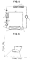
- Fig. 5 depicts a main structural part of a vapor compression refrigerating system according to still another embodiment of the present invention, using carbon dioxide refrigerant which is natural-system refrigerant.
- refrigerant compressed by compressor 1 is introduced into radiator 2, the refrigerant exchanges heat with an external fluid.
- the refrigerant passed through radiator 2 is reduced in pressure by first pressure reducing mechanism 3 provided at the exit side of radiator 2.
- the pressure reduced refrigerant (m) passes through cooler 4, and is reduced further in pressure by second pressure reducing mechanism 6.
- the pressure reduced refrigerant (m') is divided into portions by refrigerant branching mechanism 5.
- refrigerant (m1) exchanges heat in cooler 4 with refrigerant (m) is reduced in pressure by first pressure reducing mechanism 3, by cooler 4, and the refrigerant (m) reduced in pressure by first pressure reducing mechanism 3 is reduced.
- Another portion of refrigerant (m2) is introduced into evaporator 8.
- Refrigerant (m2') flowing from evaporator 8 and refrigerant (m1') passed through cooler 4 flow into accumulator 9 provided as a gas/liquid separator and are mixed therein.
- accumulator 9 stores liquid refrigerant, and releases the refrigerant gas component of the received refrigerant and supplies the refrigerant gas into a part of the refrigerating system connected to compressor 1.
- Refrigerant (m1) is diverted by refrigerant branching mechanism 5, flows to the side of cooler 4, and preferably is controlled to have a volume less than that of refrigerant (m2) which flows to the side of evaporator 8.
- the diameter of the tube connected to cooler 4 may be less than the diameter of the tube connected to evaporator 8.
- second pressure reducing mechanism 6 and refrigerant branching mechanism 5 may be assembled integrally.
- first pressure reducing mechanism 3 or second pressure reducing mechanism 6 may be configured to change a degree of pressure reduction by pressure or temperature, or both, of the received refrigerant. Examples of these structures are shown in Figs. 9 and 10.
- refrigerant branching mechanism 5 when a physical value having a correlation with an outside air temperature is detected, and when the detected value is equal to or less than a predetermined value, diversion of refrigerant to cooler 4 may be prevented by refrigerant branching mechanism 5. Still further, when a physical value having a correlation with a refrigerant pressure at a higher-pressure side in the refrigerating cycle is detected, and when the detected value is equal to or less than a predetermined value, diversion of refrigerant to cooler 4 may be prevented by refrigerant branching mechanism 5.
- Fig. 6 shows a Mollier chart of the vapor compression refrigerating system according to the above-described embodiment. As shown in the Mollier chart, the refrigerant may operate in a supercritical region.
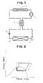
- Fig. 7 depicts a main structural part of a known vapor compression refrigerating system, using carbon dioxide refrigerant which is natural-system refrigerant.
- refrigerant compressed by compressor I is introduced into radiator 2, and the refrigerant exchanges heat with an external fluid.
- the refrigerant passed through radiator 2 is introduced into internal heat exchanger 4.
- Refrigerant flowing from internal heat exchanger 4 is reduced in pressure by first pressure reducing mechanism 3, and the pressure reduced refrigerant is introduced into evaporator 8.
- Refrigerant flowing from evaporator 8 flows into accumulator 9 provided as a gas/liquid separator.
- Refrigerant flowing from accumulator 9 is introduced into internal heat exchanger 4, and refrigerant flowing from internal heat exchanger 4 is introduced into compressor 1.
- Accumulator 9 stores liquid refrigerant, and releases the refrigerant gas component of the received refrigerant and supplies the refrigerant gas to a part of the refrigerating system connected to compressor 1.
- refrigerant flowing from radiator 2 and refrigerant flowing from accumulator 9 exchange heat with each other in internal heat exchanger 4.
- Fig. 8 shows a Mollier chart (dotted line) of the above-described known vapor compression refrigerating system and the afore-mentioned Mollier chart (solid line) of the vapor compression refrigerating system according to the embodiment of Fig. 1, together.
- Fig. 9 shows an example of a refrigerant pressure reducing mechanism in the respective embodiments, and depicts a temperature-type pressure reducing device 16.
- a temperature of refrigerant flowing from a refrigerant inlet 15 into the pressure reducing mechanism is detected by a temperature sensing part 12 comprising a diaphragm 10 charged with refrigerant 11, such as carbon dioxide.
- refrigerant 11 charged in temperature sensing part 12 varies, a valve body 13, such as a needle valve, is operated, and the degree of pressure reduction is adjusted by the variation of the opening degree of the valve.
- the pressure reduced refrigerant flows from a refrigerant outlet 17.
- Fig. 10 shows another example of a refrigerant pressure reducing mechanism in the respective embodiments, and depicts a pressure-type pressure reducing device 18.
- a valve body 19 such as a needle valve, operates against a force of a spring 20 by a pressure of refrigerant flowing from a refrigerant inlet 21 into the pressure reducing mechanism.
- the opening degree of the valve is changed, thereby adjusting the degree of pressure reduction.
- the pressure reduced refrigerant flows from a refrigerant outlet 22.
- the vapor compression refrigerating system according to the present invention is suitable, in particular, for a refrigerating system using carbon dioxide which is a natural-system refrigerant, and especially suitable as a refrigerating system used for an air conditioning system for vehicles.
Landscapes
- Engineering & Computer Science (AREA)
- Physics & Mathematics (AREA)
- Mechanical Engineering (AREA)
- Thermal Sciences (AREA)
- General Engineering & Computer Science (AREA)
- Chemical & Material Sciences (AREA)
- Analytical Chemistry (AREA)
- Power Engineering (AREA)
- Chemical Kinetics & Catalysis (AREA)
- Air-Conditioning For Vehicles (AREA)
Abstract
Description
- This application claims the benefit of
Japanese Patent Application No. 2005-351750, filed December 6, 2005 - The present invention relates to vapor compression refrigerating systems, and specifically, to vapor compression refrigerating systems using carbon dioxide refrigerant suitable for use in an air conditioning system for vehicles.
- In a case in which carbon dioxide refrigerant, which is a natural-system refrigerant, is used as refrigerant for a vapor compression refrigerating system, a structure is disclosed in
Japanese Patent Application No. H07-294033 A - Further, as another method for improving an efficiency of a refrigerating system, a structure is disclosed, for example, in
Japanese Patent Application No. H11-193967 A - Thus, in a refrigerating system having an internal heat exchanger, refrigerant at an exit side of a radiator exchanges heat with refrigerant at a suction side of a compressor. Further, when using carbon dioxide refrigerant, although the temperature refrigerant discharged from a compressor is reduced by a radiator, if a temperature of an external fluid (for example, air), which exchanges heat with the refrigerant in the radiator, reaches or exceeds a certain temperature (for example, critical temperature of carbon dioxide), the refrigerant at the exit to the radiator may not condense and may remain at a supercritical condition. If the refrigerant pressure is reduced, and if the refrigerant is evaporated by an evaporator, the refrigerating capacity may be reduced significantly. Therefore, by the heat exchange between the refrigerant at the exit side of the radiator and the refrigerant at the suction side of the compressor, the refrigerating capacity may be increased or maintained, the higher pressure-side pressure may be reduced as compared with that of a refrigerating system having no internal heat exchanger, and the coefficient of performance of the refrigerating cycle may be increased.
- In the above-described refrigerating system including an internal heat exchanger, however, because the refrigerant at an exit side of a radiator exchanges heat with the refrigerant at a suction side of a compressor, when the load of the refrigerating system is elevated, the superheating degree of the refrigerant at the suction side of the compressor also is elevated. As a result, the discharge temperature of the compressor also may be elevated to an undesirable level. Thus, it becomes necessary to increase the thermal resistance of the compressor itself in order to protect the compressor. Further, if the superheating degree of refrigerant drawn into the compressor increases, the power required for compressing operation of the compressor may increase. Therefore, in the above-described refrigerant system, the need to increase the thermal resistance of the compressor and the increased power required for compressor operation may be undesirable.
- Accordingly, it would be desirable to provide vapor compression refrigerating systems, in particular, vapor compression refrigerating systems using carbon dioxide refrigerant, which may reduce the degree of superheating of the refrigerant at a suction side of a compressor, and which may increase a coefficient of performance of the refrigerating system.
- A vapor compression refrigerating system according to the present invention may operate at a supercritical condition, and has a compressor for compressing refrigerant; a radiator for reducing the temperature of refrigerant with an elevated temperature and an elevated pressure due to compression by the compressor, a first pressure-reducing means for reducing a pressure of refrigerant, the temperature of which is reduced by the radiator; a refrigerant branching means for dividing refrigerant (m) reduced in pressure by the first pressure-reducing means into a plurality of portions, a second pressure-reducing means for reducing a pressure of one portion of the refrigerant (m1) divided by the refrigerant branching means; and a third pressure-reducing means for reducing a pressure of another portion of the refrigerant (m2) divided by the refrigerant branching means, wherein the temperature of refrigerant compressed by the compressor is reduced by the radiator, the refrigerant passed through the radiator is reduced in pressure by the first pressure-reducing means. The pressure reduced refrigerant (m) is divided by the refrigerant branching means into portions, one portion of the refrigerant (m1) is reduced in pressure by the second pressure-reducing means. The pressure reduced refrigerant (m1') exchanges heat with refrigerant present between the first pressure-reducing means and the third pressure-reducing means by a cooler. Another portion of the refrigerant (m2) is reduced in pressure by the third pressure-reducing means. The pressure reduced refrigerant (m2') is evaporated by an evaporator, and the evaporated refrigerant (m2") and the refrigerant (m1') having passed through the cooler are mixed by an accumulator a gas/liquid separator provided for separating refrigerant gas and liquid refrigerant, and the mixed refrigerant is introduced into the compressor (i.e., a first vapor compression refrigerating system).
- In this vapor compression refrigerating system, a structure may be employed wherein the temperature of refrigerant compressed by the compressor is reduced by the radiator, the pressure of refrigerant passed through the radiator is reduced by the first pressure-reducing means, the pressure reduced refrigerant (m) is divided by the refrigerant branching means into a plurality of portions, one portion of refrigerant (m1) is reduced in pressure by the second pressure-reducing means, and the pressure reduced refrigerant (m1') exchanges heat with refrigerant (m) reduced in pressure by the first pressure-reducing means and before being divided by the refrigerant branching means by the cooler, thereby reducing the temperature of the refrigerant (m) reduced in pressure by the first pressure-reducing means. Another portion of refrigerant (m2) is reduced in pressure by the third pressure-reducing means, the pressure reduced refrigerant (m2') is evaporated by the evaporator, the evaporated refrigerant (m2'') and the refrigerant (m1') having passed through the cooler are mixed by the gas/liquid separator (e.g., the accumulator), and the mixed refrigerant is introduced into the compressor. In this embodiment, a structure may be employed wherein the second pressure-reducing means, the third pressure-reducing means, and the refrigerant branching means are assembled integrally.
- Further, a structure also may be employed wherein the temperature of refrigerant compressed by the compressor is reduced by the radiator, the refrigerant passed through radiator is reduced in pressure by the first pressure-reducing means, and the pressure reduced refrigerant (m) is divided by the refrigerant branching means into a plurality of portions, one portion of refrigerant (m1) is reduced in pressure by the second pressure-reducing means, and the pressure reduced refrigerant (m1') exchanges heat with another portion of refrigerant (m2) divided by the refrigerant branching means by the cooler, thereby reducing the temperature of refrigerant (m2). The refrigerant (m2) passed through the cooler is reduced in pressure by the third pressure-reducing means, the pressure reduced refrigerant (m2') is evaporated by the evaporator, the evaporated refrigerant (m2'') and the refrigerant (m1') having passed through the cooler are mixed by the gas/liquid separator (e.g., the accumulator), and the mixed refrigerant is introduced into the compressor. In this embodiment, a structure may be employed wherein the first pressure-reducing means, the second pressure-reducing means and the refrigerant branching means are assembled integrally.
- In this first vapor compression refrigerating system, a structure may be employed wherein the first pressure-reducing means is configured to adjust a degree of pressure reduction, and the degree of pressure reduction is adjusted by a pressure or a temperature, or both, of refrigerant flowing into the first pressure-reducing means. Further, a structure may be employed wherein the second pressure-reducing means is configured to adjust a degree of pressure reduction, and the degree of pressure reduction is adjusted by a pressure or a temperature, or both, of refrigerant flowing into the second pressure-reducing means. Moreover, a structure may be employed wherein the third pressure-reducing means is configured to adjust a degree of pressure reduction, and the degree of pressure reduction is adjusted by a pressure or a temperature, or both of refrigerant flowing into the third pressure-reducing means. Further, a structure may be employed wherein a degree of pressure reduction of the second pressure-reducing means and a degree of pressure reduction of the third pressure-reducing means are adjusted at a same rate.
- Further, a structure may be employed wherein an outside air temperature detecting means for detecting a physical value having a correlation with an outside air temperature is provided, and when the physical value having a correlation with an outside air temperature detected by the outside air temperature detecting means is equal to or less than a predetermined value, the second pressure-reducing means is closed. In an embodiment, a structure may be employed wherein an outside air temperature detecting means for detecting a physical value having a correlation with an outside air temperature is provided, and when the physical value having a correlation with an outside air temperature detected by the outside air temperature detecting means is equal to or less than a predetermined value, the refrigerant branching means prevents the flow of refrigerant into the cooler. In another embodiment, a structure may be employed wherein a higher pressure detecting means for detecting a physical value having a correlation with a refrigerant pressure at a higher-pressure side in the refrigerating system from the compressor to the first pressure-reducing means is provided, and when the physical value having a correlation with a refrigerant pressure at the higher-pressure side detected by the higher pressure detecting means is equal to or less than a predetermined value, the second pressure-reducing means is closed. In still another embodiment, a structure may be employed wherein a higher pressure detecting means for detecting a physical value having a correlation with a refrigerant pressure at a high-pressure side in the refrigerating cycle from the compressor to the first pressure-reducing means is provided, and when the physical value having a correlation with a refrigerant pressure at the high-pressure side detected by the high pressure detecting means is equal to or less than a predetermined value, the refrigerant branching means stops directing refrigerant into the cooler.
- Further, a vapor compression refrigerating system, according to the present invention, may operate at a supercritical condition and comprises a compressor for compressing refrigerant, a radiator for reducing the temperature of refrigerant with an elevated temperature and an elevated pressure compressed by the compressor, a first pressure-reducing means for reducing a pressure of refrigerant having been passed through the radiator, a second pressure-reducing means for further reducing a pressure of refrigerant (m) reduced in pressure by the first pressure-reducing means, and a refrigerant branching means for dividing the pressure reduced refrigerant. The temperature of refrigerant compressed by the compressor is reduced by the radiator, the refrigerant passed through the radiator is reduced in pressure by the first pressure-reducing means, the pressure reduced refrigerant (m) is reduced further in pressure by the second pressure-reducing means, and the pressure reduced refrigerant (m') is divided by the refrigerant branching means into a plurality of portions, one portion refrigerant (m1) exchanges heat with the refrigerant (m) reduced in pressure by the first pressure-reducing means by a cooler, thereby reducing the temperature of the pressure reduced refrigerant (m). An other portion of refrigerant (m2) is evaporated by an evaporator, the evaporated refrigerant (m2') and the refrigerant (m1') having passed through the cooler are mixed by a gas/liquid separator (e.g., an accumulator) provided for separating gas/liquid of refrigerant, and the mixed refrigerant is introduced into the compressor (i.e., a second vapor compression refrigerating system).
- In this second vapor compression refrigerating system, a structure may be employed wherein the second pressure-reducing means and the refrigerant branching means are assembled integrally.
- Further, a structure also may be employed wherein the first pressure-reducing means is configured to adjust a degree of pressure reduction, and the degree of pressure reduction is adjusted by a pressure or a temperature, or both, of refrigerant flowing into the first pressure-reducing means. Further, a structure may be employed wherein an outside air temperature detecting means for detecting a physical value having a correlation with an outside air temperature is provided, and when the physical value having a correlation with an outside air temperature detected by the outside air temperature detecting means is equal to or less than a predetermined value, the refrigerant branching means prevents the flow of refrigerant into the cooler. In another embodiment, a structure may be employed wherein a higher pressure detecting means for detecting a physical value having a correlation with a refrigerant pressure at a higher-pressure side in said refrigerating cycle from the compressor to the first pressure-reducing means is provided, and when the physical value having a correlation with a refrigerant pressure at the higher-pressure side detected by the higher pressure detecting means is equal to or less than a predetermined value, the refrigerant branching means prevents the flow of refrigerant into the cooler.
- In the first and second vapor compression refrigerating systems according to the present invention, carbon dioxide refrigerant preferably is used. The vapor compression refrigerating systems are suitable for use for air conditioning systems for vehicles.
- Thus, in the vapor compression refrigerating system according to the present invention, and particularly as a vapor compression refrigerating system using carbon dioxide refrigerant which is a natural-system refrigerant, the dryness of the refrigerant of the refrigerating system at an entrance of the evaporator may be reduced, and the refrigerating capacity of the evaporator may be increased. Further, the superheating degree of refrigerant at the suction side of the compressor may be reduced as compared with that in the known refrigerating system using an internal heat exchanger for exchanging heat between the suction side of the compressor and the exit side of the radiator. Because the efficiency of the compressor may be improved and the discharge temperature thereof may be lowered, the coefficient of performance of the refrigerating system may be increased.
- Further objects, features, and advantages of the present invention will be understood from the following detailed description of preferred embodiments of the present invention with reference to the accompanying figures.
- Embodiments of the invention now are described with reference to the accompanying figures, which are given by way of example only, and are not intended to limit the present invention.
- Fig. 1 is a schematic diagram of a vapor compression refrigerating system according to an embodiment of the present invention.
- Fig. 2 is a Mollier chart of the vapor compression refrigerating system depicted in Fig. 1.
- Fig. 3 is a schematic diagram of a vapor compression refrigerating system according to another embodiment of the present invention.
- Fig. 4 is a Mollier chart of the vapor compression refrigerating system depicted in Fig. 3.
- Fig. 5 is a schematic diagram of a vapor compression refrigerating system according to still another embodiment of the present invention.
- Fig. 6 is a Mollier chart of the vapor compression refrigerating system depicted in Fig. 5.
- Fig. 7 is a schematic diagram of a known vapor compression refrigerating system.
- Fig. 8 is a Mollier chart of the vapor compression refrigerating system depicted in Fig. 7.
- Fig. 9 is a schematic sectional view of a temperature-type pressure reducing device showing an example of a refrigerant pressure reducing mechanism.
- Fig. 10 is a schematic sectional view of a pressure-type pressure reducing device showing an example of a refrigerant pressure reducing mechanism.
- Fig. 1 depicts a main structural part of a vapor compression refrigerating system according to an embodiment of the present invention, using carbon dioxide refrigerant which is natural-system refrigerant. In this refrigerating system, refrigerant compressed by a
compressor 1 is introduced into aradiator 2, the refrigerant exchanges heat with an external fluid. The refrigerant passed throughradiator 2 is reduced in pressure by a firstpressure reducing mechanism 3 provided as a first pressure-reducing means at the exit side ofradiator 2. The pressure reduced refrigerant (m) is divided into a plurality of portions by a refrigerant branching mechanism 5 provided as a refrigerant branching means. One portion of refrigerant (m1) is reduced in pressure by a secondpressure reducing mechanism 6 provided as a second pressure-reducing means, the pressure reduced refrigerant (m1') exchanges heat with the refrigerant (m) in acooler 4, and the temperature of refrigerant (m) is reduced before refrigerant (m) is divided. Further, another portion of refrigerant (m2) is divided by refrigerant branching mechanism 5 and is reduced in pressure by a thirdpressure reducing mechanism 7 provided as a third pressure-reducing means, and the pressure reduced refrigerant (m2') is introduced into anevaporator 8. After refrigerant (m2") flows out fromevaporator 8 and after refrigerant (m1') passes through cooler 4, refrigerants (m2" and m1') flow into anaccumulator 9 provided as a gas/liquid separator and are mixed therein.Accumulator 9 stores liquid refrigerant, and releases the refrigerant gas components of the received refrigerant.Accumulator 9 also supplies refrigerant gas a part of the refrigerating system connected tocompressor 1. - Refrigerant (m1) is diverted by refrigerant branching mechanism 5 and flowing to the side of second
pressure reducing mechanism 6 and preferably is controlled to have a volume less than that of refrigerant (m2) which flows to the side of thirdpressure reducing mechanism 7. For example, the diameter of the tube connected to secondpressure reducing mechanism 6 may be less than the diameter of the tube connected to thirdpressure reducing mechanism 7. - Further, second and third
pressure reducing mechanisms pressure reducing mechanism 6. Moreover, secondpressure reducing mechanism 6 or thirdpressure reducing mechanism 7 may be configured to change a degree of pressure reduction or the temperature of the received refrigerant. More concretely, these structures are shown in Figs. 9 and 10. Moreover, it is preferred that degrees of pressure reduction at second and thirdpressure reducing mechanisms - Further, when a physical value having a correlation with an outside air temperature is detected, and when the detected value is equal to or less than a predetermined value, the refrigerant passage may be closed by second
pressure reducing mechanism 6 configured to adjust a degree of pressure reduction, or diversion of refrigerant to cooler 4 may be prevented by refrigerant branching mechanism 5. In addition, when a physical value having a correlation with a refrigerant pressure at a higher-pressure side in the refrigerating system is detected, and when the detected value is equal to or less than a predetermined value, the refrigerant passage may be closed by secondpressure reducing mechanism 6 configured to adjust a degree of pressure reduction, or diversion of refrigerant to cooler 4 may be prevented by refrigerant branching mechanism 5. - Fig. 2 shows a Mollier chart of the vapor compression refrigerating system according to the above-described embodiment. As shown in the Mollier chart, the refrigerant may operate in a supercritical region. In Fig. 2, portions of the chart depicted by double lines show operations of divided refrigerants. The same convention is used in the following Mollier charts.
- Fig. 3 depicts a main structural part of a vapor compression refrigerating system according to another embodiment of the present invention, using carbon dioxide refrigerant which is natural-system refrigerant. In this refrigerating system, refrigerant compressed by
compressor 1 is introduced intoradiator 2, the refrigerant exchanges heat with an external fluid. The refrigerant passed throughradiator 2 is reduced in pressure by firstpressure reducing mechanism 3 provided at the exit side ofradiator 2. The pressure reduced refrigerant (m) is divided into portions by refrigerant branching mechanism 5. One portion of refrigerant (m1) is reduced in pressure by secondpressure reducing mechanism 6, the pressure reduced refrigerant (m1') exchanges heat with another portion of refrigerant (m2) incooler 4, and the temperature of the divided refrigerant (m2) is reduced. After passing throughcooler 4, the refrigerant (m2) is reduced in pressure by thirdpressure reducing mechanism 7, and the pressure reduced refrigerant (m2') is introduced intoevaporator 8. Refrigerant (m2") flowing out fromevaporator 8 and refrigerant (m1') having passed through cooler 4 flow intoaccumulator 9 provided as a gas/liquid separator and are mixed therein. Similar to in the previous embodiment,accumulator 9 stores liquid refrigerant, and releases the refrigerant gas component of the received refrigerant and supplies the refrigerant gas to a part of the refrigerating system connected tocompressor 1. - Refrigerant (m1) is diverted by refrigerant branching mechanism 5, flows to the side of second
pressure reducing mechanism 6, and preferably is controlled to have a volume less than that of refrigerant (m2) which flows to the side ofcooler 4. For example, the diameter of the tube connected to secondpressure reducing mechanism 6 may be less than the diameter of the tube connected to cooler 4. Further, first and secondpressure reducing mechanisms pressure reducing mechanism 6. Moreover, secondpressure reducing mechanism 6 or thirdpressure reducing mechanism 7 may be configured to change a degree of pressure reduction by pressure or temperature, or both, of the received refrigerant. Examples of these structures are shown in Figs. 9 and 10. Moreover, it is preferred that degrees of pressure reduction at second and thirdpressure reducing mechanisms - Further, when a physical value having a correlation with an outside air temperature is detected, and when the detected value is equal to or less than a predetermined value, the refrigerant passage may be closed by second
pressure reducing mechanism 6 which is configured to adjust a degree of pressure reduction, or diversion of refrigerant to cooler 4 may be prevented by refrigerant branching mechanism 5. In addition, when a physical value having a correlation with a refrigerant pressure at a higher-pressure side in the refrigerating cycle is detected, and when the detected value is equal to or less than a predetermined value, the refrigerant passage may be closed by secondpressure reducing mechanism 6 which is configured to adjust a degree of pressure reduction, or diversion of refrigerant to cooler 4 may be prevented by refrigerant branching mechanism 5. - Fig. 4 shows a Mollier chart of the vapor compression refrigerating system according to the above-described embodiment. As shown in the Mollier chart, the refrigerant may operate in a supercritical region.
- Fig. 5 depicts a main structural part of a vapor compression refrigerating system according to still another embodiment of the present invention, using carbon dioxide refrigerant which is natural-system refrigerant. In this refrigerating system, refrigerant compressed by
compressor 1 is introduced intoradiator 2, the refrigerant exchanges heat with an external fluid. The refrigerant passed throughradiator 2 is reduced in pressure by firstpressure reducing mechanism 3 provided at the exit side ofradiator 2. The pressure reduced refrigerant (m) passes through cooler 4, and is reduced further in pressure by secondpressure reducing mechanism 6. The pressure reduced refrigerant (m') is divided into portions by refrigerant branching mechanism 5. One portion of refrigerant (m1) exchanges heat in cooler 4 with refrigerant (m) is reduced in pressure by firstpressure reducing mechanism 3, by cooler 4, and the refrigerant (m) reduced in pressure by firstpressure reducing mechanism 3 is reduced. Another portion of refrigerant (m2) is introduced intoevaporator 8. Refrigerant (m2') flowing fromevaporator 8 and refrigerant (m1') passed through cooler 4 flow intoaccumulator 9 provided as a gas/liquid separator and are mixed therein. As described above,accumulator 9 stores liquid refrigerant, and releases the refrigerant gas component of the received refrigerant and supplies the refrigerant gas into a part of the refrigerating system connected tocompressor 1. - Refrigerant (m1) is diverted by refrigerant branching mechanism 5, flows to the side of cooler 4, and preferably is controlled to have a volume less than that of refrigerant (m2) which flows to the side of
evaporator 8. For example, the diameter of the tube connected to cooler 4 may be less than the diameter of the tube connected toevaporator 8. In addition, secondpressure reducing mechanism 6 and refrigerant branching mechanism 5 may be assembled integrally. Moreover, firstpressure reducing mechanism 3 or secondpressure reducing mechanism 6 may be configured to change a degree of pressure reduction by pressure or temperature, or both, of the received refrigerant. Examples of these structures are shown in Figs. 9 and 10. Further, when a physical value having a correlation with an outside air temperature is detected, and when the detected value is equal to or less than a predetermined value, diversion of refrigerant to cooler 4 may be prevented by refrigerant branching mechanism 5. Still further, when a physical value having a correlation with a refrigerant pressure at a higher-pressure side in the refrigerating cycle is detected, and when the detected value is equal to or less than a predetermined value, diversion of refrigerant to cooler 4 may be prevented by refrigerant branching mechanism 5. - Fig. 6 shows a Mollier chart of the vapor compression refrigerating system according to the above-described embodiment. As shown in the Mollier chart, the refrigerant may operate in a supercritical region.
- For comparison, Fig. 7 depicts a main structural part of a known vapor compression refrigerating system, using carbon dioxide refrigerant which is natural-system refrigerant. In this refrigerating system, refrigerant compressed by compressor I is introduced into
radiator 2, and the refrigerant exchanges heat with an external fluid. The refrigerant passed throughradiator 2 is introduced intointernal heat exchanger 4. Refrigerant flowing frominternal heat exchanger 4 is reduced in pressure by firstpressure reducing mechanism 3, and the pressure reduced refrigerant is introduced intoevaporator 8. Refrigerant flowing fromevaporator 8 flows intoaccumulator 9 provided as a gas/liquid separator. Refrigerant flowing fromaccumulator 9 is introduced intointernal heat exchanger 4, and refrigerant flowing frominternal heat exchanger 4 is introduced intocompressor 1.Accumulator 9 stores liquid refrigerant, and releases the refrigerant gas component of the received refrigerant and supplies the refrigerant gas to a part of the refrigerating system connected tocompressor 1. Moreover, refrigerant flowing fromradiator 2 and refrigerant flowing fromaccumulator 9 exchange heat with each other ininternal heat exchanger 4. - Fig. 8 shows a Mollier chart (dotted line) of the above-described known vapor compression refrigerating system and the afore-mentioned Mollier chart (solid line) of the vapor compression refrigerating system according to the embodiment of Fig. 1, together.
- Fig. 9 shows an example of a refrigerant pressure reducing mechanism in the respective embodiments, and depicts a temperature-type
pressure reducing device 16. In temperature-typepressure reducing device 16, a temperature of refrigerant flowing from arefrigerant inlet 15 into the pressure reducing mechanism is detected by atemperature sensing part 12 comprising adiaphragm 10 charged withrefrigerant 11, such as carbon dioxide. When the pressure ofrefrigerant 11 charged intemperature sensing part 12 varies, avalve body 13, such as a needle valve, is operated, and the degree of pressure reduction is adjusted by the variation of the opening degree of the valve. The pressure reduced refrigerant flows from arefrigerant outlet 17. - Fig. 10 shows another example of a refrigerant pressure reducing mechanism in the respective embodiments, and depicts a pressure-type
pressure reducing device 18. In pressure-typepressure reducing device 18, avalve body 19, such as a needle valve, operates against a force of aspring 20 by a pressure of refrigerant flowing from arefrigerant inlet 21 into the pressure reducing mechanism. The opening degree of the valve is changed, thereby adjusting the degree of pressure reduction. The pressure reduced refrigerant flows from arefrigerant outlet 22. - In the above-described vapor compression refrigerating systems according to the embodiments of Figs. 1 and 5, in vapor compression refrigerating systems using carbon dioxide which is natural-system refrigerant, particularly as shown in Fig. 8 by comparison with the known system, the dryness of refrigerant at the entrance of the evaporator in the refrigerating system may be reduced, and the refrigerating ability of the evaporator may be increased. Further, the superheating degree at the suction side of the compressor may be reduced as compared with that in the known system using an internal heat exchanger for heat exchange between the suction side of the compressor and the exit side of the radiator. A difference between the solid line and the dotted line at the right end portion in the Mollier chart depicted in Fig. 8. Because the efficiency of the compressor may be increased and the discharge temperature may be reduced, the efficiency of the vapor compression refrigerating system may be significantly increased.
- The vapor compression refrigerating system according to the present invention is suitable, in particular, for a refrigerating system using carbon dioxide which is a natural-system refrigerant, and especially suitable as a refrigerating system used for an air conditioning system for vehicles.
Claims (19)
- A vapor compression refrigerating system configured to operate at a supercritical condition, comprising:a compressor for compressing a refrigerant;a radiator for reducing a temperature of refrigerant with an elevated temperature and an elevated pressure after the refrigerant passes through the compressor;a first pressure-reducing means for reducing a pressure of refrigerant after the refrigerant passes through the radiator;a refrigerant branching means for dividing refrigerant into a plurality of portions after the refrigerant is reduced in pressure by the first pressure-reducing means;a second pressure-reducing means for reducing a pressure of a first portion of the refrigerant divided by the refrigerant branching means; anda third pressure-reducing means for reducing a pressure of a second portion of the refrigerant divided by the refrigerant branching means;a cooler, wherein after the first portion of the refrigerant passes through the second pressure-reducing means, the first portion of the refrigerant exchanges heat with the refrigerant flowing between the first pressure-reducing means and the third pressure-reducing means;an evaporator, wherein after the second portion of the refrigerant passes through the third pressure-reducing means, the second portion of the refrigerant is evaporated; anda gas/liquid separator, in which the evaporated refrigerant and the first portion of the refrigerant are mixed and a refrigerant gas component is separated from a liquid refrigerant component of the mixed refrigerant and from which the mixed refrigerant flows into the compressor.
- The vapor compression refrigerating system of claim 1, wherein the second pressure-reducing means, the third pressure-reducing means and the refrigerant branching means are formed integrally.
- The vapor compression refrigerating system of claim 1, wherein the first pressure-reducing means is configured to adjust a degree of pressure reduction, and the degree of pressure reduction is adjusted by a pressure or a temperature, or both, of refrigerant flowing into the first pressure-reducing means.
- The vapor compression refrigerating system of claim 1, wherein the second pressure-reducing means is configured to adjust a degree of pressure reduction, and the degree of pressure reduction is adjusted by a pressure or a temperature, or both, of refrigerant flowing into the second pressure-reducing means.
- The vapor compression refrigerating system of claim 1, wherein the third pressure-reducing means is configured to adjust a degree of pressure reduction, and the degree of pressure reduction is adjusted by a pressure or a temperature, or both, of refrigerant flowing into the third pressure-reducing means.
- The vapor compression refrigerating system of claim 1, wherein a degree of pressure reduction of the second pressure-reducing means and a degree of pressure reduction of the third pressure-reducing means are changed at a same rate.
- The vapor compression refrigerating system of claim 1, further comprising an outside air temperature detecting means for detecting a physical value having a correlation with an outside air temperature, and when the physical value having a correlation with an outside air temperature detected by the outside air temperature detecting means is equal to or less than a predetermined value, the second pressure-reducing means is closed.
- The vapor compression refrigerating system of claim 1, further comprising an outside air temperature detecting means for detecting a physical value having a correlation with an outside air temperature, and when the physical value having a correlation with an outside air temperature detected by the outside air temperature detecting means is equal to or less than a predetermined value, the refrigerant branching means prevents refrigerant from flowing into the cooler.
- The vapor compression refrigerating system of claim 1, further comprising a higher pressure detecting means for detecting a physical value having a correlation with a refrigerant pressure at a higher-pressure side in the refrigerating cycle from the compressor to the first pressure-reducing means, and when the physical value having a correlation with a refrigerant pressure at the higher-pressure side detected by the higher pressure detecting means is equal to or less than a predetermined value, the second pressure-reducing means is closed.
- The vapor compression refrigerating system of claim 1, further comprising a higher pressure detecting means for detecting a physical value having a correlation with a refrigerant pressure at a higher-pressure side in the refrigerating cycle from the compressor to the first pressure-reducing means, and when the physical value having a correlation with a refrigerant pressure at the higher-pressure side detected by the higher pressure detecting means is equal to or less than a predetermined value, the refrigerant branching means prevents refrigerant from flowing into the cooler.
- The vapor compression refrigerating system of claim 1, wherein the refrigerant is carbon dioxide.
- An air conditioning system for a vehicle comprising the vapor compression refrigerating system of claim 1.
- A vapor compression refrigerating system configured to operate at a supercritical condition, comprising:a compressor for compressing a refrigerant;a radiator for reducing the temperature of refrigerant with an elevated temperature and an elevated pressure compressed by the compressor;a first pressure-reducing means for reducing a pressure of refrigerant passed through the radiator;a second pressure-reducing means for further reducing a pressure of the refrigerant reduced in pressure by the first pressure-reducing means;a refrigerant branching means for dividing the pressure reduced refrigerant, in which the refrigerant is divided into a plurality of portions;a cooler, in which a first portion of the refrigerant exchanges heat with the refrigerant reduced in pressure by the first pressure-reducing means, thereby reducing the temperature of the pressure reduced refrigerant;an evaporator, in which a second portion of the refrigerant is evaporated; anda gas/liquid separator, in which the evaporated refrigerant and the refrigerant having passed through the cooler are mixed to separate a refrigerant gas component from a liquid refrigerant component of the mixed refrigerant, and the mixed refrigerant flows into the compressor.
- The vapor compression refrigerating system of claim 13, wherein the second pressure-reducing means and the refrigerant branching means are formed integrally.
- The vapor compression refrigerating system of claim 13, wherein the first pressure-reducing means is configured to adjust a degree of pressure reduction, and the degree of pressure reduction is adjusted by a pressure or a temperature, or both, of refrigerant flowing into the first pressure-reducing means.
- The vapor compression refrigerating system of claim 13, further comprising an outside air temperature detecting means for detecting a physical value having a correlation with an outside air temperature, and when the physical value having a correlation with an outside air temperature detected by the outside air temperature detecting means is equal to or less than a predetermined value, the refrigerant branching means prevents refrigerant from flowing into the cooler.
- The vapor compression refrigerating system of claim 13, further comprising a higher pressure detecting means for detecting a physical value having a correlation with a refrigerant pressure at a higher-pressure side in the refrigerating cycle from the compressor to the first pressure-reducing means, and when the physical value having a correlation with a refrigerant pressure at the higher-pressure side detected by the higher pressure detecting means is equal to or less than a predetermined value, the refrigerant branching means prevents refrigerant from flowing into the cooler.
- The vapor compression refrigerating system of claim 13, wherein the refrigerant is carbon dioxide.
- An air conditioning system for a vehicle comprising the vapor compression refrigerating cycle of claim 13.
Applications Claiming Priority (1)
| Application Number | Priority Date | Filing Date | Title |
|---|---|---|---|
| JP2005351750A JP2007155229A (en) | 2005-12-06 | 2005-12-06 | Vapor compression type refrigerating cycle |
Publications (2)
| Publication Number | Publication Date |
|---|---|
| EP1795834A2 true EP1795834A2 (en) | 2007-06-13 |
| EP1795834A3 EP1795834A3 (en) | 2008-10-08 |
Family
ID=37876923
Family Applications (1)
| Application Number | Title | Priority Date | Filing Date |
|---|---|---|---|
| EP06125365A Withdrawn EP1795834A3 (en) | 2005-12-06 | 2006-12-04 | Vapor compression refrigerating system |
Country Status (3)
| Country | Link |
|---|---|
| US (1) | US7370493B2 (en) |
| EP (1) | EP1795834A3 (en) |
| JP (1) | JP2007155229A (en) |
Cited By (3)
| Publication number | Priority date | Publication date | Assignee | Title |
|---|---|---|---|---|
| WO2009017968A1 (en) * | 2007-07-27 | 2009-02-05 | Johnson Controls Technology Company | Economized vapor compression circuit |
| US20140165635A1 (en) * | 2011-11-07 | 2014-06-19 | Mitsubishi Electric Corporation | Air-conditioning apparatus |
| EP2434236A3 (en) * | 2010-09-27 | 2015-06-03 | LG Electronics, Inc. | Refrigerant system and a control method of the same |
Families Citing this family (13)
| Publication number | Priority date | Publication date | Assignee | Title |
|---|---|---|---|---|
| JP5473922B2 (en) | 2007-10-09 | 2014-04-16 | ビーイー・エアロスペース・インコーポレーテッド | Thermal control system |
| US9989280B2 (en) * | 2008-05-02 | 2018-06-05 | Heatcraft Refrigeration Products Llc | Cascade cooling system with intercycle cooling or additional vapor condensation cycle |
| JP5180680B2 (en) * | 2008-05-20 | 2013-04-10 | サンデン株式会社 | Refrigeration cycle |
| JP2010032159A (en) * | 2008-07-30 | 2010-02-12 | Denso Corp | Refrigerating cycle device |
| EP2672200B1 (en) * | 2011-02-04 | 2017-10-18 | Toyota Jidosha Kabushiki Kaisha | Cooling device |
| CN103162374B (en) * | 2011-12-12 | 2016-03-30 | 珠海格力电器股份有限公司 | control method and device of air conditioner system |
| CN103196202B (en) * | 2012-01-09 | 2015-08-05 | 珠海格力电器股份有限公司 | Air conditioner and control method thereof |
| US20150047385A1 (en) * | 2013-08-15 | 2015-02-19 | Heat Pump Technologies, LLC | Partitioned evaporator for a reversible heat pump system operating in the heating mode |
| WO2019049255A1 (en) * | 2017-09-07 | 2019-03-14 | 三菱電機株式会社 | Air conditioning device |
| CN110940106B (en) * | 2018-09-25 | 2021-06-18 | 杭州三花研究院有限公司 | Air conditioning system and control method thereof |
| WO2020063678A1 (en) | 2018-09-25 | 2020-04-02 | 杭州三花研究院有限公司 | Air conditioning system and control method therefor |
| US12078397B2 (en) | 2020-12-04 | 2024-09-03 | Honeywell International Inc. | Surge control subcooling circuit |
| EP4137755A1 (en) * | 2021-08-21 | 2023-02-22 | Carrier Corporation | Enhanced economizer operation in a chiller |
Family Cites Families (17)
| Publication number | Priority date | Publication date | Assignee | Title |
|---|---|---|---|---|
| JPH06241584A (en) * | 1993-02-19 | 1994-08-30 | Mitsubishi Electric Corp | Refrigeration cycle |
| DE19522884A1 (en) * | 1995-06-23 | 1997-01-02 | Inst Luft Kaeltetech Gem Gmbh | Compression refrigeration circuit operating system |
| FR2755756B1 (en) * | 1996-11-12 | 1999-01-15 | Valeo Climatisation | MODULAR COMPONENT FOR A REFRIGERANT FLUID CIRCUIT, PARTICULARLY FOR AIR CONDITIONING THE INTERIOR OF A MOTOR VEHICLE |
| JPH1144461A (en) * | 1997-07-24 | 1999-02-16 | Daikin Ind Ltd | refrigerator |
| JP2000097523A (en) * | 1998-09-24 | 2000-04-04 | Zexel Corp | Inflation device of super-critical refrigeration cycle |
| JP2000304374A (en) * | 1999-04-22 | 2000-11-02 | Yanmar Diesel Engine Co Ltd | Engine heat pump |
| JP3607998B2 (en) * | 1999-03-05 | 2005-01-05 | 大陽日酸株式会社 | Container valve with decompression function |
| JP3740380B2 (en) * | 2000-04-19 | 2006-02-01 | 株式会社デンソー | Heat pump water heater |
| JP2001317832A (en) * | 2000-05-10 | 2001-11-16 | Daikin Ind Ltd | Air conditioner |
| JP2001343173A (en) * | 2000-05-31 | 2001-12-14 | Matsushita Electric Ind Co Ltd | Refrigeration cycle device for CO2 refrigerant |
| JP3838008B2 (en) * | 2000-09-06 | 2006-10-25 | 松下電器産業株式会社 | Refrigeration cycle equipment |
| JP2002156161A (en) * | 2000-11-16 | 2002-05-31 | Mitsubishi Heavy Ind Ltd | Air conditioner |
| JP2002235679A (en) * | 2001-02-09 | 2002-08-23 | Mitsubishi Heavy Ind Ltd | Scroll compressor |
| JP2002267279A (en) * | 2001-03-06 | 2002-09-18 | Zexel Valeo Climate Control Corp | Refrigeration cycle controller |
| JP3801006B2 (en) * | 2001-06-11 | 2006-07-26 | ダイキン工業株式会社 | Refrigerant circuit |
| JP4074487B2 (en) * | 2001-07-13 | 2008-04-09 | 株式会社荏原製作所 | Dehumidifying air conditioner |
| JP4273493B2 (en) * | 2004-02-16 | 2009-06-03 | 三菱電機株式会社 | Refrigeration air conditioner |
-
2005
- 2005-12-06 JP JP2005351750A patent/JP2007155229A/en active Pending
-
2006
- 2006-12-04 EP EP06125365A patent/EP1795834A3/en not_active Withdrawn
- 2006-12-06 US US11/567,505 patent/US7370493B2/en not_active Expired - Fee Related
Cited By (6)
| Publication number | Priority date | Publication date | Assignee | Title |
|---|---|---|---|---|
| WO2009017968A1 (en) * | 2007-07-27 | 2009-02-05 | Johnson Controls Technology Company | Economized vapor compression circuit |
| US8713963B2 (en) | 2007-07-27 | 2014-05-06 | Johnson Controls Technology Company | Economized vapor compression circuit |
| EP2434236A3 (en) * | 2010-09-27 | 2015-06-03 | LG Electronics, Inc. | Refrigerant system and a control method of the same |
| US20140165635A1 (en) * | 2011-11-07 | 2014-06-19 | Mitsubishi Electric Corporation | Air-conditioning apparatus |
| EP2778566A4 (en) * | 2011-11-07 | 2015-07-15 | Mitsubishi Electric Corp | AIR CONDITIONING APPARATUS |
| US9759460B2 (en) * | 2011-11-07 | 2017-09-12 | Mitsubishi Electric Corporation | Air-conditioning apparatus |
Also Published As
| Publication number | Publication date |
|---|---|
| US7370493B2 (en) | 2008-05-13 |
| EP1795834A3 (en) | 2008-10-08 |
| JP2007155229A (en) | 2007-06-21 |
| US20070125121A1 (en) | 2007-06-07 |
Similar Documents
| Publication | Publication Date | Title |
|---|---|---|
| US7370493B2 (en) | Vapor compression refrigerating systems | |
| EP1347251B1 (en) | Method for increasing efficiency of a vapor compression system by evaporator heating | |
| US6651451B2 (en) | Variable capacity refrigeration system with a single-frequency compressor | |
| JP3813702B2 (en) | Vapor compression refrigeration cycle | |
| JP4285060B2 (en) | Vapor compression refrigerator | |
| JP3925545B2 (en) | Refrigeration equipment | |
| EP1860390A2 (en) | Vapor compression refrigerating cycle | |
| JP4408413B2 (en) | Refrigeration apparatus and air conditioner using the same | |
| WO2008094157A1 (en) | Enhanced refrigerant system | |
| JP2000035250A (en) | Supercritical refrigeration cycle | |
| EP2587177A2 (en) | Air conditioner | |
| EP1959214A2 (en) | Expansion valve mechanism and passage switching device | |
| EP2147264A1 (en) | Refrigerant vapor compression system and method of transcritical operation | |
| US12203687B2 (en) | Cooling system with flooded low side heat exchangers | |
| KR20060053142A (en) | Refrigeration Units & Air Conditioners | |
| EP1855068A2 (en) | Vapor compression refrigerating cycle | |
| US20050103045A1 (en) | Air conditioner | |
| JPH10288411A (en) | Vapor compression refrigeration cycle | |
| JP2007155230A (en) | Air conditioner | |
| US11519645B2 (en) | Air conditioning apparatus | |
| JP4352327B2 (en) | Ejector cycle | |
| WO2011072679A1 (en) | A vapour compression system with split evaporator | |
| JP2005098635A (en) | Refrigeration cycle | |
| EP1801521A2 (en) | Pressure reduce module with oil seperator | |
| WO2018159323A1 (en) | Ejector module and evaporator unit |
Legal Events
| Date | Code | Title | Description |
|---|---|---|---|
| PUAI | Public reference made under article 153(3) epc to a published international application that has entered the european phase |
Free format text: ORIGINAL CODE: 0009012 |
|
| AK | Designated contracting states |
Kind code of ref document: A2 Designated state(s): AT BE BG CH CY CZ DE DK EE ES FI FR GB GR HU IE IS IT LI LT LU LV MC NL PL PT RO SE SI SK TR |
|
| AX | Request for extension of the european patent |
Extension state: AL BA HR MK YU |
|
| PUAL | Search report despatched |
Free format text: ORIGINAL CODE: 0009013 |
|
| AK | Designated contracting states |
Kind code of ref document: A3 Designated state(s): AT BE BG CH CY CZ DE DK EE ES FI FR GB GR HU IE IS IT LI LT LU LV MC NL PL PT RO SE SI SK TR |
|
| AX | Request for extension of the european patent |
Extension state: AL BA HR MK RS |
|
| PUAF | Information related to the publication of a search report (a3 document) modified or deleted |
Free format text: ORIGINAL CODE: 0009199SEPU |
|
| PUAL | Search report despatched |
Free format text: ORIGINAL CODE: 0009013 |
|
| D17D | Deferred search report published (deleted) | ||
| AK | Designated contracting states |
Kind code of ref document: A3 Designated state(s): AT BE BG CH CY CZ DE DK EE ES FI FR GB GR HU IE IS IT LI LT LU LV MC NL PL PT RO SE SI SK TR |
|
| AX | Request for extension of the european patent |
Extension state: AL BA HR MK RS |
|
| RIC1 | Information provided on ipc code assigned before grant |
Ipc: F25B 40/00 20060101ALI20080904BHEP Ipc: F25B 43/00 20060101ALI20080904BHEP Ipc: F25B 9/00 20060101AFI20070328BHEP |
|
| AKX | Designation fees paid | ||
| REG | Reference to a national code |
Ref country code: DE Ref legal event code: 8566 |
|
| STAA | Information on the status of an ep patent application or granted ep patent |
Free format text: STATUS: THE APPLICATION IS DEEMED TO BE WITHDRAWN |
|
| 18D | Application deemed to be withdrawn |
Effective date: 20090409 |