EP1795770B1 - Cylindrical roller bearing - Google Patents
Cylindrical roller bearing Download PDFInfo
- Publication number
- EP1795770B1 EP1795770B1 EP05783315A EP05783315A EP1795770B1 EP 1795770 B1 EP1795770 B1 EP 1795770B1 EP 05783315 A EP05783315 A EP 05783315A EP 05783315 A EP05783315 A EP 05783315A EP 1795770 B1 EP1795770 B1 EP 1795770B1
- Authority
- EP
- European Patent Office
- Prior art keywords
- cylindrical roller
- flange
- contact
- chamfer
- height
- Prior art date
- Legal status (The legal status is an assumption and is not a legal conclusion. Google has not performed a legal analysis and makes no representation as to the accuracy of the status listed.)
- Expired - Fee Related
Links
Images

Classifications
-
- F—MECHANICAL ENGINEERING; LIGHTING; HEATING; WEAPONS; BLASTING
- F16—ENGINEERING ELEMENTS AND UNITS; GENERAL MEASURES FOR PRODUCING AND MAINTAINING EFFECTIVE FUNCTIONING OF MACHINES OR INSTALLATIONS; THERMAL INSULATION IN GENERAL
- F16C—SHAFTS; FLEXIBLE SHAFTS; ELEMENTS OR CRANKSHAFT MECHANISMS; ROTARY BODIES OTHER THAN GEARING ELEMENTS; BEARINGS
- F16C33/00—Parts of bearings; Special methods for making bearings or parts thereof
- F16C33/30—Parts of ball or roller bearings
- F16C33/58—Raceways; Race rings
- F16C33/583—Details of specific parts of races
- F16C33/585—Details of specific parts of races of raceways, e.g. ribs to guide the rollers
-
- F—MECHANICAL ENGINEERING; LIGHTING; HEATING; WEAPONS; BLASTING
- F16—ENGINEERING ELEMENTS AND UNITS; GENERAL MEASURES FOR PRODUCING AND MAINTAINING EFFECTIVE FUNCTIONING OF MACHINES OR INSTALLATIONS; THERMAL INSULATION IN GENERAL
- F16C—SHAFTS; FLEXIBLE SHAFTS; ELEMENTS OR CRANKSHAFT MECHANISMS; ROTARY BODIES OTHER THAN GEARING ELEMENTS; BEARINGS
- F16C19/00—Bearings with rolling contact, for exclusively rotary movement
- F16C19/22—Bearings with rolling contact, for exclusively rotary movement with bearing rollers essentially of the same size in one or more circular rows, e.g. needle bearings
- F16C19/225—Details of the ribs supporting the end of the rollers
-
- F—MECHANICAL ENGINEERING; LIGHTING; HEATING; WEAPONS; BLASTING
- F16—ENGINEERING ELEMENTS AND UNITS; GENERAL MEASURES FOR PRODUCING AND MAINTAINING EFFECTIVE FUNCTIONING OF MACHINES OR INSTALLATIONS; THERMAL INSULATION IN GENERAL
- F16C—SHAFTS; FLEXIBLE SHAFTS; ELEMENTS OR CRANKSHAFT MECHANISMS; ROTARY BODIES OTHER THAN GEARING ELEMENTS; BEARINGS
- F16C19/00—Bearings with rolling contact, for exclusively rotary movement
- F16C19/22—Bearings with rolling contact, for exclusively rotary movement with bearing rollers essentially of the same size in one or more circular rows, e.g. needle bearings
- F16C19/24—Bearings with rolling contact, for exclusively rotary movement with bearing rollers essentially of the same size in one or more circular rows, e.g. needle bearings for radial load mainly
- F16C19/26—Bearings with rolling contact, for exclusively rotary movement with bearing rollers essentially of the same size in one or more circular rows, e.g. needle bearings for radial load mainly with a single row of rollers
-
- F—MECHANICAL ENGINEERING; LIGHTING; HEATING; WEAPONS; BLASTING
- F16—ENGINEERING ELEMENTS AND UNITS; GENERAL MEASURES FOR PRODUCING AND MAINTAINING EFFECTIVE FUNCTIONING OF MACHINES OR INSTALLATIONS; THERMAL INSULATION IN GENERAL
- F16C—SHAFTS; FLEXIBLE SHAFTS; ELEMENTS OR CRANKSHAFT MECHANISMS; ROTARY BODIES OTHER THAN GEARING ELEMENTS; BEARINGS
- F16C33/00—Parts of bearings; Special methods for making bearings or parts thereof
- F16C33/30—Parts of ball or roller bearings
- F16C33/34—Rollers; Needles
-
- F—MECHANICAL ENGINEERING; LIGHTING; HEATING; WEAPONS; BLASTING
- F16—ENGINEERING ELEMENTS AND UNITS; GENERAL MEASURES FOR PRODUCING AND MAINTAINING EFFECTIVE FUNCTIONING OF MACHINES OR INSTALLATIONS; THERMAL INSULATION IN GENERAL
- F16C—SHAFTS; FLEXIBLE SHAFTS; ELEMENTS OR CRANKSHAFT MECHANISMS; ROTARY BODIES OTHER THAN GEARING ELEMENTS; BEARINGS
- F16C2240/00—Specified values or numerical ranges of parameters; Relations between them
- F16C2240/40—Linear dimensions, e.g. length, radius, thickness, gap
- F16C2240/42—Groove sizes
-
- F—MECHANICAL ENGINEERING; LIGHTING; HEATING; WEAPONS; BLASTING
- F16—ENGINEERING ELEMENTS AND UNITS; GENERAL MEASURES FOR PRODUCING AND MAINTAINING EFFECTIVE FUNCTIONING OF MACHINES OR INSTALLATIONS; THERMAL INSULATION IN GENERAL
- F16C—SHAFTS; FLEXIBLE SHAFTS; ELEMENTS OR CRANKSHAFT MECHANISMS; ROTARY BODIES OTHER THAN GEARING ELEMENTS; BEARINGS
- F16C2240/00—Specified values or numerical ranges of parameters; Relations between them
- F16C2240/40—Linear dimensions, e.g. length, radius, thickness, gap
- F16C2240/70—Diameters; Radii
Definitions
- the present invention relates to a cylindrical roller bearing suitable for supporting a shaft rotating at high speed and high load in a wind power generation speed-up gear, a machine tool, a jet engine, a gas turbine and the like.
- a general cylindrical roller bearing comprises an inner ring having a track surface around its outer periphery, an outer ring having a track surface around its inner periphery, a plurality of cylindrical rollers arranged between the track surface of the inner ring and the track surface of the outer ring so that they can roll freely, and a retainer retaining the cylindrical rollers at a predetermined intervals in a circumferential direction.
- a relief groove is provided at the corner in which the flange surface of the flange and the track surface of the inner ring cross.
- This relief groove is provided as a relief region when the track surface and the flange surface are ground.
- a chamfer is provided at the corner part in which the rolling surface and the end surface of the cylindrical roller cross. The axial dimension between the flange surfaces opposed to each other in an axis direction is set a little larger than the length of the cylindrical roller, whereby a guide clearance is provided between the cylindrical roller and the flange.
- the cylindrical roller bearing described above since the rolling surface of the cylindrical roller and the track surface of the track ring are linearly in contact with each other, it has a high load facility of a radial load and it is suitable for high-speed rotation, but a heating value is great at the time of high-speed rotation as compared with a boll bearing, and it has a problem in that a lot of heat and abrasion are likely to be generated at the sliding contact part between the cylindrical roller and the flange, especially.
- the cylindrical roller has a degree of freedom for inclination by the above-described guide clearance, so that it is inevitable that the axis line of the cylindrical roller is inclined with respect to the axis line of the bearing, that is, a skew is generated at the time of rotation of the bearing.
- a skew is generated at the time of rotation of the bearing.
- the height of a relief groove is made larger than that of a chamfer of a cylindrical roller, and a tapered surface extending to the outside in an axial direction at a predetermined angle is provided in a flange surface, to improve the lubricant state of the above sliding contact part.
- the cylindrical roller since the cylindrical roller has the degree of freedom for inclination by the guide clearance, while the cylindrical roller rotating and revolving at the time of the bearing rotation, it constantly varying its posture within a maximum skew angle.
- a cylindrical roller 1 when a cylindrical roller 1 is skewed at a skew angle ⁇ smaller than a maximum skew angle ⁇ max, the cylindrical roller 1 is pressed to one side in the axial direction by the axial thrust force F and guided to roll in the state in which it is pressed to one flange surface 2a of an inner ring 2.
- the contact state between the cylindrical roller 1 and the flange surface 2a varies with the skew angle ⁇ as follows.
- Fig. 4 shows the relation (solid line) between the skew angle ⁇ of the cylindrical roller 1 and the contact surface pressure P between the cylindrical roller 1 and the flange 2a, and the relation (dotted line) between the skew angle e and the axial thrust force F applied to the cylindrical roller 1.
- the axial thrust force F is increased as the skew angle ⁇ is increased.
- the contact surface pressure P is relatively steeply increased as the skew angle ⁇ is increased. This is related to the fact that the cylindrical roller 1 and the flange 2a come into contact with each other at the boundary B1 and the boundary B2 (shown in Fig. 2 ), and the axial thrust force F is increased as the skew angle ⁇ is increased.
- the contact surface pressure P becomes a surface pressure level P0 or more in which the contact part is abraded.
- the contact surface pressure P is reduced to the surface pressure level P0 or less, and it makes a stable shift at a relatively low value although the skew angle ⁇ is increased.
- This means that the contact state between the cylindrical roller 1 and the flange 2a is shifted from the contact between the boundary B1 and the boundary B2 (shown in Fig. 2 ) to the contact between the boundary B1 and the flange surface 2b (shown in Fig. 3 ).
- the contact surface pressure P between the cylindrical roller and the flange becomes the surface pressure level P0 or more in which the contact part is abraded before the skew angle ⁇ becomes the maximum skew angle ⁇ max, that is, in the range ⁇ 0 ⁇ ⁇ ⁇ ⁇ 1 and ⁇ 2 ⁇ ⁇ ⁇ ⁇ max, which is attributed to the major factor of the heat generation and abrasion at the contact part.
- a critical skew angle ⁇ 1 that is a maximum skew angle in which the boundary between the end surface of a cylindrical roller and a chamfer comes into contact with the boundary between a flange surface and a relief groove is regulated to a predetermined angle or less.
- a relief groove 2c is provided at a corner in which a flange surface 2b of each flange 2a and a track surface 2e of an inner ring 2 cross.
- the relief groove 2c is provided as a relief region when the track surface 2e and the flange surface 2b are ground mainly.
- the flange surface 2b is tapered such that it is gradually opened in an outer diameter direction, and a chamfer 2d is provided at a corner part in which the flange surface 2b and an outer diameter surface 2f of the flange 2a cross.
- a chamfer 1b is provided at the corner part in which a rolling surface 1c and an end surface 1a of the cylindrical roller 1 cross. Furthermore, the axial dimension between the flange surfaces 2b opposed to each other in an axial direction is made a little larger than the length of the cylindrical roller 1, so that a guide clearance S is provided between the end surface 1a of the cylindrical roller 1 and the flange surface 2b.
- a height "H” of the relief groove 2c from the track surface 2e of the inner ring 2 is set to be larger than a height "h” of the chamfer 1b from the rolling surface 1c of the cylindrical roller 1.
- the height "H" of the relief groove 2c is the dimension from the track surface 2e to the boundary B2 between the relief groove 2c and the flange surface 2b in a radius direction.
- the height "h” of the chamfer of the cylindrical roller is the dimension from the boundary B4 between the rolling surface 1c and the chamfer 1b to the boundary B1 between the chamfer 1b and the end surface 1a in the radius direction.
- Fig. 6 shows the relation (solid line) between the skew angle ⁇ of the cylindrical roller 1, and the contact surface pressure P between the cylindrical roller 1 and the flange surface 2a, and the relation (dotted line) between the skew angle ⁇ and the axial thrust force F applied to the cylindrical roller 1 in the cylindrical roller bearing disclosed in the above Japanese Unexamined Patent Publication No. 2003-278745 .
- the contact surface pressure P is steeply increased as the skew angle ⁇ is increased in a range 0 ⁇ ⁇ ⁇ ⁇ 1, since the critical skew angle ⁇ 1 is regulated to the small angle as compared with that shown in Fig.
- the contact surface pressure P shifts at a value lower than the surface pressure level P0 in which the contact part is abraded (there is no region shown by the hatching in Fig. 4 ). More specifically, even when the cylindrical roller 1 and the flange 2a come in contact with each other at the boundary B1 and the boundary B2 (state shown in Fig. 2 ), as long as the skew angle ⁇ is small, the axial thrust force F pressing the cylindrical roller 1 toward the flange 2a is small, so that the contact surface pressure P is relatively small.
- the contact surface pressure P makes a stable shift at a relatively low value although the skew angle ⁇ is increased.
- the contact surface pressure P is steeply increased again and it becomes the surface pressure level P0 or more after the skew angle ⁇ reaches ⁇ 2.
- the angle range ( ⁇ 2 ⁇ ⁇ ⁇ ⁇ max) in which the contact surface pressure P exceeds the surface pressure level P0 is narrow.
- the contact surface pressure P is reduced by regulating the critical skew angle ⁇ 1 to the small angle and shifting the contact state between the cylindrical roller 1 and the flange 2a from the contact state (shown in Fig. 2 ) between the boundary B1 and the boundary B2 to the contact state (shown in Fig. 3 ) between the boundary B1 and the flange 2b at a smaller skew angle, so that the heat generation and the abrasion can be prevented from being generated at the contact part.
- the heat generation and abrasion at the contact part is to be further prevented by further reducing the contact surface pressure in the range of ⁇ 1 to ⁇ 2 in which the contact surface pressure is relatively low.
- the first peak of the contact surface pressure is generated by the contact between the boundary B1 (boundary between the end surface and the chamfer of the cylindrical roller) at the upper end of the chamfer of the cylindrical roller, and the boundary B2 (boundary between the relief groove and the flange surface) at the upper end of the relief groove of the track ring.
- the first peak of the contact surface pressure is to be further reduced.
- JP 2004 011821 A discloses a cylindrical roller bearing according to the preamble of claim 1.
- a cylindrical roller bearing according to the present invention comprises a track ring having flanges on both sides of its track surface and provided with a relief groove at a corner in which at least one of the flanges intersects with the track surface, and a cylindrical roller arranged so that it can freely roll on the track surface and provided with a chamfer at a corner part in which its rolling surface intersects with each end surface, wherein when it is assumed that the height of the chamfer from the rolling surface of the cylindrical roller is "h” and the curvature radius of the chamfer is "R”, the relation such that 1.0 R/h 1.5 is satisfied, the relationship between "h” and the height of the relief groove "H” and between the diameter of said cylindrical roller and "H” being according to claim 1.
- the boundary between the end surface and the chamfer of the cylindrical roller comes in contact with the flange surface of the track ring.
- An edge is left at the boundary of the cylindrical roller in general.
- the ratio of the curvature radius of the chamfer to the height of the chamfer of the cylindrical roller is set to be within a range of 1.0 to 1.5. When the ratio is equal to 1.0, the boundary can be a perfectly continuous curved surface without any edge.
- the height "h" of the chamfer is made smaller than the height "H” of the relief groove from the track surface.
- the height of the relief groove is to be reduced.
- the diameter of the cylindrical roller is more than 24mm but not more than 30mm
- the height of the relief groove is to be 1.2mm or less.
- the diameter of the cylindrical roller is more than 30mm but not more than 40mm
- the height of the relief groove is to be 1.4mm or less.
- the diameter of the cylindrical roller is more than 40mm but not more than 50mm
- the height of the relief groove is to be 1.6mm or less.
- the heat generation and the abrasion at the contact part can be prevented by further reducing the contact surface pressure of the contact part between the cylindrical roller and the flange of the track ring.
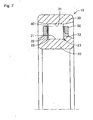
- Fig. 7 shows a cylindrical roller bearing 10 according to one embodiment of the present invention.
- the cylindrical roller bearing 10 is used in a high-load and high-speed rotating operation in a wind power generation speed-up gear, a machine tool, a jet engine, a gas turbine and the like.
- the cylindrical roller bearing 10 comprises an inner ring 20 having a track surface 21 on its outer periphery, an outer ring 30 having a track surface 31 on its inner periphery, a plurality of cylindrical rollers 40 arranged between the track surface 21 of the inner ring 20 and the track surface 31 of the outer ring 30 so as to freely roll, and a retainer 50 retaining the plurality of cylindrical roller bearings 40 at predetermined intervals in a circumferential direction.
- a flange 22 is provided on each side of the inner ring 20.
- a relief groove 23 is provided at a corner in which a flange surface 24 of the flange 22 and the track surface 21 of the inner ring 20 cross.
- This relief groove 23 is provided as a relief groove when the track surface 21 and the flange surface 24 are ground.
- the flange surface 24 is a tapered surface slanting so as to be gradually opened in an outer diameter direction, and a chamfer is provided at a corner part in which the flange surface 24 and an outer diameter surface 25 of the flange 22 cross.
- a chamfer 42 is provided at the corner in which a rolling surface 41 and end surface 43 of the cylindrical roller 40 cross.
- the distance between the flange surfaces 24 opposed to each other in an axial direction is provided so as to be a little larger than the length of the cylindrical roller 40 and a guide clearance S is provided between the end surface 43 of the cylindrical roller 40 and the flange surface 24.
- Edges are surely provided at a boundary B4 between the rolling surface 41 and chamfer 42 of the cylindrical roller 40, and a boundary B1 between the end surface 43 and the chamfer 42. This is because the rolling surface 41 and the end surface 43 are ground after the heat treatment of the cylindrical roller 40.
- the edge (angle) at the boundary B1 between the chamfer 42 and the end surface 43 of the cylindrical roller 40 is reduced as much as possible so that a continuous curved surface is provided.
- the cylindrical roller 40 is processed so as to satisfy the relation such that 1.0 ⁇ R/h ⁇ 1.5.
- R/h When the value of R/h is 1.0, since the height "h" and the curvature radius "R" of the chamfer 42 are the same, the end surface 43 becomes a tangent line of the chamfer 42, so that the edge does not exist.
- the upper limit value of the R/h is set to 1.5 because while the value R/h of the conventional cylindrical roller is approximately in a range of 2.0 to 3.0, the contact surface pressure between the cylindrical roller 40 and the flange surface 24 is to be lower than that of the conventional cylindrical roller bearing.
- the first peak of the contact surface pressure is generated by the contact between the boundary B1 at the upper end of the chamfer 42 of the cylindrical roller 40, and a boundary B2 at the upper end of the relief groove 23 of the inner ring 20.
- the height "h" of the chamfer is made smaller than the height "H" of the relief groove and the height "H” of the relief groove is made smaller than the height of the relief groove of the conventional roller bearing.
- the height "H” of the relief groove 23 is set to 1.2mm or less.
- the height "H” of the relief groove 23 is set to 1.4mm or less.
- the height "H” of the relief groove 23 is set to 1.6mm or less.
- the inventor of the present invention measured each part of the conventional cylindrical roller bearing that supports a planet gear of a wind power generation speed-up gear, and measured each part of the invented bearing. The measured result is shown in the following table 1.
- Table 1 Unit mm Cylindrical roller diameter Relief groove height Cylindrical roller chamfer More than Not more than Conventional bearing Invented bearing Conventional bearing invented bearing Chamfer height h (nominal) Chamfer curvature diameter R Ratio R/h Chamfer height h (nominal) Chamfer curvature diameter R Ratio R/h 24 30 1.44 1.1 1.2 2.5 2.1 0.8 1.2 1.5 30 40 1.73 1.3 1.5 3 2 1 1.4 1.4 40 50 1.73 1.5 2 4 2 1.2 1.6 1.3
- the inner ring has flanges on both sides of the track surface and the relief grooves are provided at the corner in which the flange surfaces of the flanges on both sides and the track surface cross in the illustrated embodiment, a relief groove may be provided only at one corner in which one flange surface and the track surface cross in another embodiment.
- the outer ring has a flange surface
- the dimensional relation as described above is applied to the relation between the flange surface of the outer ring and the cylindrical roller.
- the term "track ring” described in the claim includes one or both of the inner ring and the outer ring.
- the present invention can be advantageously applied to a cylindrical roller bearing used in a high-load and high-speed rotating operation in a wind power generation speed-up gear, a machine tool, a jet engine, a gas turbine and the like.
Abstract
Description
- The present invention relates to a cylindrical roller bearing suitable for supporting a shaft rotating at high speed and high load in a wind power generation speed-up gear, a machine tool, a jet engine, a gas turbine and the like.
- A general cylindrical roller bearing comprises an inner ring having a track surface around its outer periphery, an outer ring having a track surface around its inner periphery, a plurality of cylindrical rollers arranged between the track surface of the inner ring and the track surface of the outer ring so that they can roll freely, and a retainer retaining the cylindrical rollers at a predetermined intervals in a circumferential direction.
- For example, when the inner ring comprises flanges at both ends, a relief groove is provided at the corner in which the flange surface of the flange and the track surface of the inner ring cross. This relief groove is provided as a relief region when the track surface and the flange surface are ground. In addition, a chamfer is provided at the corner part in which the rolling surface and the end surface of the cylindrical roller cross. The axial dimension between the flange surfaces opposed to each other in an axis direction is set a little larger than the length of the cylindrical roller, whereby a guide clearance is provided between the cylindrical roller and the flange.
- According to the cylindrical roller bearing described above, since the rolling surface of the cylindrical roller and the track surface of the track ring are linearly in contact with each other, it has a high load facility of a radial load and it is suitable for high-speed rotation, but a heating value is great at the time of high-speed rotation as compared with a boll bearing, and it has a problem in that a lot of heat and abrasion are likely to be generated at the sliding contact part between the cylindrical roller and the flange, especially. More specifically, the cylindrical roller has a degree of freedom for inclination by the above-described guide clearance, so that it is inevitable that the axis line of the cylindrical roller is inclined with respect to the axis line of the bearing, that is, a skew is generated at the time of rotation of the bearing. When the cylindrical roller is skewed, an axial component is generated in the driving force applied from the track surface of the rotating side, and it becomes axial thrust force F that presses the end of the cylindrical roller to one flange. Thus, the friction resistance at the sliding contact part between the cylindrical roller and the flange surface is increased, which causes heat generation and abrasion in some cases.
- Various kinds of improvements have been proposed for the above problems. For example, according to Japanese Patent Publication No.
58-43609 - In addition, according to Japanese Unexamined Patent Publication No.
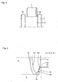
7-12119 - As described above, since the cylindrical roller has the degree of freedom for inclination by the guide clearance, while the cylindrical roller rotating and revolving at the time of the bearing rotation, it constantly varying its posture within a maximum skew angle. As schematically shown in
Fig. 1 , when acylindrical roller 1 is skewed at a skew angle θ smaller than a maximum skew angle θ max, thecylindrical roller 1 is pressed to one side in the axial direction by the axial thrust force F and guided to roll in the state in which it is pressed to oneflange surface 2a of aninner ring 2. At this time, the contact state between thecylindrical roller 1 and theflange surface 2a varies with the skew angle θ as follows. - That is, when the skew angle θ is in a
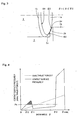
range 0 < θ <θ 1, a boundary B1 between anend surface 1a and achamfer 1b of thecylindrical roller 1 is in contact with a boundary B2 between aflange surface 2b and arelief groove 2c as shown inFig. 2 (contact point is shown by a black circle ●), and when the skew angle θ is in arange θ 1< θ <θ 2, the boundary B1 between theend surface 1a and thechamfer 1b of thecylindrical roller 1 is in contact with theflange surface 2b as shown inFig. 3 (contact point is shown by a black circle ●). Thus, when the skew angle θ is about to become approximately 2 θ, the boundary B1 between theend surface 1a and thechamfer 1b of thecylindrical roller 1 is in contact with a boundary B3 between theflange surface 2b and aflange surface chamfer 2d (not shown). Then, both ends of thecylindrical roller 1 come in contact with bothflange surfaces 2a, respectively and the skew angle θ reaches the maximum skew angle θ max (not shown). -
Fig. 4 shows the relation (solid line) between the skew angle θ of thecylindrical roller 1 and the contact surface pressure P between thecylindrical roller 1 and theflange 2a, and the relation (dotted line) between the skew angle e and the axial thrust force F applied to thecylindrical roller 1. As shown inFig. 4 , the axial thrust force F is increased as the skew angle θ is increased. - In the
range 0 < θ <θ 1, the contact surface pressure P is relatively steeply increased as the skew angle θ is increased. This is related to the fact that thecylindrical roller 1 and theflange 2a come into contact with each other at the boundary B1 and the boundary B2 (shown inFig. 2 ), and the axial thrust force F is increased as the skew angle θ is increased. Especially, in therange θ 0 < θ < θ 1 (region shown by crossed hatching inFig. 4 ), it has been confirmed from a test that the contact surface pressure P becomes a surface pressure level P0 or more in which the contact part is abraded. - When the skew angle becomes more than
θ 1, the contact surface pressure P is reduced to the surface pressure level P0 or less, and it makes a stable shift at a relatively low value although the skew angle θ is increased. This means that the contact state between thecylindrical roller 1 and theflange 2a is shifted from the contact between the boundary B1 and the boundary B2 (shown inFig. 2 ) to the contact between the boundary B1 and theflange surface 2b (shown inFig. 3 ). - When the skew angle θ becomes approximately
θ 2, the contact surface pressure P is rapidly increased again and when the skew angle θ becomesθ 2, it becomes the surface pressure level P0 or more. This means that the contact state between thecylindrical roller 1 and theflange 2a is shifted from the contact between the boundary B1 and theflange surface 2b (shown inFig 3 ) to the contact state between the boundary B1 and the boundary B3. - As described above, the contact surface pressure P between the cylindrical roller and the flange becomes the surface pressure level P0 or more in which the contact part is abraded before the skew angle θ becomes the maximum skew angle θ max, that is, in the
range θ 0 < θ <θ 1 andθ 2< θ < θ max, which is attributed to the major factor of the heat generation and abrasion at the contact part. - However, according to the above Japanese Patent Publication No.
58-43609 7-12119 - The same applicant of this application has proposed a cylindrical roller bearing suitable for the higher-speed rotation in Japanese Unexamined Patent Publication No.
2003-278745 skew angle θ 1 that is a maximum skew angle in which the boundary between the end surface of a cylindrical roller and a chamfer comes into contact with the boundary between a flange surface and a relief groove is regulated to a predetermined angle or less. Thus, the contact state between the cylindrical roller and the flange is shifted from the contact between the boundaries (shown inFig 2 ), to the contact between the boundary and the flange surface (shown inFig. 3 ) at a smaller skew angle, so that a contact surface pressure can be reduced. - The above Japanese Unexamined Patent Publication No.
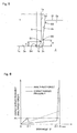
2003-278745 Fig. 5 , arelief groove 2c is provided at a corner in which aflange surface 2b of eachflange 2a and atrack surface 2e of aninner ring 2 cross. Therelief groove 2c is provided as a relief region when thetrack surface 2e and theflange surface 2b are ground mainly. Theflange surface 2b is tapered such that it is gradually opened in an outer diameter direction, and achamfer 2d is provided at a corner part in which theflange surface 2b and anouter diameter surface 2f of theflange 2a cross. Furthermore, achamfer 1b is provided at the corner part in which arolling surface 1c and anend surface 1a of thecylindrical roller 1 cross. Furthermore, the axial dimension between theflange surfaces 2b opposed to each other in an axial direction is made a little larger than the length of thecylindrical roller 1, so that a guide clearance S is provided between theend surface 1a of thecylindrical roller 1 and theflange surface 2b. - A height "H" of the
relief groove 2c from thetrack surface 2e of theinner ring 2 is set to be larger than a height "h" of thechamfer 1b from therolling surface 1c of thecylindrical roller 1. Thus, a difference δ (δ= H-h) between the height "H" of therelief groove 2c and the height "h" of thechamfer 1b of the cylindrical roller is regulated to a predetermined value or less, so that the above-described criticalskew angle θ 1 can be regulated to the predetermined angle or less. - In addition, the height "H" of the
relief groove 2c is the dimension from thetrack surface 2e to the boundary B2 between therelief groove 2c and theflange surface 2b in a radius direction. In addition, the height "h" of the chamfer of the cylindrical roller is the dimension from the boundary B4 between therolling surface 1c and thechamfer 1b to the boundary B1 between thechamfer 1b and theend surface 1a in the radius direction. -
Fig. 6 shows the relation (solid line) between the skew angle θ of thecylindrical roller 1, and the contact surface pressure P between thecylindrical roller 1 and theflange surface 2a, and the relation (dotted line) between the skew angle θ and the axial thrust force F applied to thecylindrical roller 1 in the cylindrical roller bearing disclosed in the above Japanese Unexamined Patent Publication No.2003-278745 range 0 < θ <θ 1, since the criticalskew angle θ 1 is regulated to the small angle as compared with that shown inFig. 4 , the contact surface pressure P shifts at a value lower than the surface pressure level P0 in which the contact part is abraded (there is no region shown by the hatching inFig. 4 ). More specifically, even when thecylindrical roller 1 and theflange 2a come in contact with each other at the boundary B1 and the boundary B2 (state shown inFig. 2 ), as long as the skew angle θ is small, the axial thrust force F pressing thecylindrical roller 1 toward theflange 2a is small, so that the contact surface pressure P is relatively small. - In a
range θ 1< θ <θ 2, similar to that shown inFig. 4 , the contact surface pressure P makes a stable shift at a relatively low value although the skew angle θ is increased. When the skew angle θ becomes approximatelyθ 2, the contact surface pressure P is steeply increased again and it becomes the surface pressure level P0 or more after the skew angle θ reachesθ 2. However, since the maximum skew angle θ max is regulated to the small angle, the angle range (θ 2< θ < θ max) in which the contact surface pressure P exceeds the surface pressure level P0 is narrow. - As described above, the contact surface pressure P is reduced by regulating the critical
skew angle θ 1 to the small angle and shifting the contact state between thecylindrical roller 1 and theflange 2a from the contact state (shown inFig. 2 ) between the boundary B1 and the boundary B2 to the contact state (shown inFig. 3 ) between the boundary B1 and theflange 2b at a smaller skew angle, so that the heat generation and the abrasion can be prevented from being generated at the contact part. - According to the cylindrical roller bearing disclosed in the above Japanese Unexamined Patent Publication No.
2003-278745 2003-278745 Fig. 6 ) in the range ofθ 1 toθ 2. For example, the cylindrical roller bearing for the planet gear in the wind power generation speed-up gear rotates at high speed in a highly-loaded state. In the case of the cylindrical roller bearing used in such highly-loaded and rotating at high speed, it is desirable that the heat generation and abrasion at the contact part is to be further prevented by further reducing the contact surface pressure in the range ofθ 1 toθ 2 in which the contact surface pressure is relatively low. - In addition, as shown in
Fig. 6 , the first peak of the contact surface pressure is generated by the contact between the boundary B1 (boundary between the end surface and the chamfer of the cylindrical roller) at the upper end of the chamfer of the cylindrical roller, and the boundary B2 (boundary between the relief groove and the flange surface) at the upper end of the relief groove of the track ring. Preferably, the first peak of the contact surface pressure is to be further reduced. - Furthermore, the
JP 2004 011821 A claim 1. - It is an object of the present invention to provide a cylindrical roller bearing suitable for being used in a high-load and high-speed rotation by improving the cylindrical roller bearing disclosed in the above Japanese Unexamined Patent Publication No.
2003-278745 - A cylindrical roller bearing according to the present invention comprises a track ring having flanges on both sides of its track surface and provided with a relief groove at a corner in which at least one of the flanges intersects with the track surface, and a cylindrical roller arranged so that it can freely roll on the track surface and provided with a chamfer at a corner part in which its rolling surface intersects with each end surface, wherein when it is assumed that the height of the chamfer from the rolling surface of the cylindrical roller is "h" and the curvature radius of the chamfer is "R", the relation such that 1.0 R/h 1.5 is satisfied, the relationship between "h" and the height of the relief groove "H" and between the diameter of said cylindrical roller and "H" being according to
claim 1. - When the cylindrical roller is skewed on the track surface of the track ring, the boundary between the end surface and the chamfer of the cylindrical roller comes in contact with the flange surface of the track ring. An edge is left at the boundary of the cylindrical roller in general. In order to reduce the contact surface pressure between the cylindrical roller and the flange surface of the track ring, it is desirable that the edge at the boundary of the cylindrical roller is reduced as much as possible so that a continuously curved surface is provided. Thus, according to the present invention, in order to reduce the edge at the boundary, the ratio of the curvature radius of the chamfer to the height of the chamfer of the cylindrical roller is set to be within a range of 1.0 to 1.5. When the ratio is equal to 1.0, the boundary can be a perfectly continuous curved surface without any edge.
- In order to improve the lubricant state of the sliding contact part between the cylindrical roller and the flange of the track ring, the height "h" of the chamfer is made smaller than the height "H" of the relief groove from the track surface.
- In the case where the track ring is the inner ring, the higher the relief groove from the track surface is, the higher the peripheral velocity of the boundary between the relief groove and the flange surface is. As a result, the contact surface pressure between the cylindrical roller and inner ring becomes high. In order to reduce the contact surface pressure, the height of the relief groove is to be reduced. When the diameter of the cylindrical roller is more than 24mm but not more than 30mm, the height of the relief groove is to be 1.2mm or less. When the diameter of the cylindrical roller is more than 30mm but not more than 40mm, the height of the relief groove is to be 1.4mm or less. When the diameter of the cylindrical roller is more than 40mm but not more than 50mm, the height of the relief groove is to be 1.6mm or less.
- As described above, according to the present invention, the heat generation and the abrasion at the contact part can be prevented by further reducing the contact surface pressure of the contact part between the cylindrical roller and the flange of the track ring.
-
-
Fig. 1 is a view schematically showing a state in which a cylindrical roller is skewed and it is in contact with one flange; -
Fig. 2 is a view showing a state in which the boundary between the end surface and the chamfer of the cylindrical roller is in contact with the boundary between a flange surface and a relief groove; -
Fig. 3 is a view showing a state in which the boundary between the end surface and the chamfer of the cylindrical roller is in contact with the flange surface; -
Fig: 4 is a view showing the relation (solid line) between the skew angle θ of the cylindrical roller, and the contact surface pressure P between the cylindrical roller and the flange, and the relation (dotted line) between the skew angle θ and the axial thrust force F applied to the cylindrical roller; -
Fig. 5 is an enlarged sectional view showing a peripheral part of the end of the cylindrical roller and the flange; -
Fig. 6 shows the relation (solid line) between the skew angle θ of the cylindrical roller, and the contact surface pressure P between the cylindrical roller and the flange, and the relation (dotted line) between the skew angle θ and the axial thrust force F applied to the cylindrical roller in the cylindrical roller bearing disclosed in the above Japanese Unexamined Patent Publication No.2003-278745 -
Fig. 7 is a sectional view showing a cylindrical roller bearing according to one embodiment of the present invention; and -
Fig. 8 is an enlarged sectional view showing the end of a cylindrical roller and a flange according to one embodiment of the present invention. -
Fig. 7 shows acylindrical roller bearing 10 according to one embodiment of the present invention. Thecylindrical roller bearing 10 is used in a high-load and high-speed rotating operation in a wind power generation speed-up gear, a machine tool, a jet engine, a gas turbine and the like. - The
cylindrical roller bearing 10 comprises aninner ring 20 having atrack surface 21 on its outer periphery, anouter ring 30 having atrack surface 31 on its inner periphery, a plurality ofcylindrical rollers 40 arranged between thetrack surface 21 of theinner ring 20 and thetrack surface 31 of theouter ring 30 so as to freely roll, and aretainer 50 retaining the plurality ofcylindrical roller bearings 40 at predetermined intervals in a circumferential direction. Aflange 22 is provided on each side of theinner ring 20. - As shown in an enlarged view in
Fig. 8 , arelief groove 23 is provided at a corner in which aflange surface 24 of theflange 22 and thetrack surface 21 of theinner ring 20 cross. Thisrelief groove 23 is provided as a relief groove when thetrack surface 21 and theflange surface 24 are ground. According to this embodiment, theflange surface 24 is a tapered surface slanting so as to be gradually opened in an outer diameter direction, and a chamfer is provided at a corner part in which theflange surface 24 and anouter diameter surface 25 of theflange 22 cross. - A
chamfer 42 is provided at the corner in which a rollingsurface 41 andend surface 43 of thecylindrical roller 40 cross. The distance between the flange surfaces 24 opposed to each other in an axial direction is provided so as to be a little larger than the length of thecylindrical roller 40 and a guide clearance S is provided between theend surface 43 of thecylindrical roller 40 and theflange surface 24. - Edges are surely provided at a boundary B4 between the rolling
surface 41 andchamfer 42 of thecylindrical roller 40, and a boundary B1 between theend surface 43 and thechamfer 42. This is because the rollingsurface 41 and theend surface 43 are ground after the heat treatment of thecylindrical roller 40. - As described above, in order to lower the contact surface pressure between the
cylindrical roller 40 and theflange surface 24 of theinner ring 20, it is preferable that the edge (angle) at the boundary B1 between thechamfer 42 and theend surface 43 of thecylindrical roller 40 is reduced as much as possible so that a continuous curved surface is provided. Thus, according to the illustrated embodiment, when it is assumed that the height of the chamfer of thecylindrical roller 40 from the rollingsurface 41 is "h", and the curvature radius of thechamfer 42 is "R", thecylindrical roller 40 is processed so as to satisfy the relation such that 1.0 ≤ R/h ≤ 1.5. When the value of R/h is 1.0, since the height "h" and the curvature radius "R" of thechamfer 42 are the same, theend surface 43 becomes a tangent line of thechamfer 42, so that the edge does not exist. The upper limit value of the R/h is set to 1.5 because while the value R/h of the conventional cylindrical roller is approximately in a range of 2.0 to 3.0, the contact surface pressure between thecylindrical roller 40 and theflange surface 24 is to be lower than that of the conventional cylindrical roller bearing. - As described above with reference to
Fig. 6 , the first peak of the contact surface pressure is generated by the contact between the boundary B1 at the upper end of thechamfer 42 of thecylindrical roller 40, and a boundary B2 at the upper end of therelief groove 23 of theinner ring 20. According to this embodiment, in order to reduce the value of the first peak of the contact surface pressure and improve a lubricant state of a sliding contact part, the height "h" of the chamfer is made smaller than the height "H" of the relief groove and the height "H" of the relief groove is made smaller than the height of the relief groove of the conventional roller bearing. When the height "H" (height of the relief groove 23) of the boundary B2 between therelief groove 23 and theflange surface 24 of theinner ring 20 is increased, a radius "L" from the rotation axis line of theinner ring 20 to the boundary B2 is increased and the peripheral velocity of the boundary B2 is increased. The higher the peripheral velocity at the boundary B2 is, the higher the contact surface pressure between the boundary B1 of thecylindrical roller 40 and the boundary B2 of theinner ring 20 is. In this respect, it is desirable to reduce the height "H" of the boundary B2 in order to reduce the first peak of the contact surface pressure. - For example, when the diameter of the
cylindrical roller 40 is more than 24mm but not more than 30mm, the height "H" of therelief groove 23 is set to 1.2mm or less. In addition, when the diameter of thecylindrical roller 40 is more than 30mm but not more than 40mm, the height "H" of therelief groove 23 is set to 1.4mm or less. Furthermore, when the diameter of thecylindrical roller 40 is more than 40mm but not more than 50mm, the height "H" of therelief groove 23 is set to 1.6mm or less. - The inventor of the present invention measured each part of the conventional cylindrical roller bearing that supports a planet gear of a wind power generation speed-up gear, and measured each part of the invented bearing. The measured result is shown in the following table 1.
[Table 1] Unit mm Cylindrical roller diameter Relief groove height Cylindrical roller chamfer More than Not more than Conventional bearing Invented bearing Conventional bearing invented bearing Chamfer height h (nominal) Chamfer curvature diameter R Ratio R/h Chamfer height h (nominal) Chamfer curvature diameter R Ratio R/ h 24 30 1.44 1.1 1.2 2.5 2.1 0.8 1.2 1.5 30 40 1.73 1.3 1.5 3 2 1 1.4 1.4 40 50 1.73 1.5 2 4 2 1.2 1.6 1.3 - As can be clear from the measured result shown in Table 1, while the value R/h of the conventional bearing is 2 or more, the value R/h of the invented bearing is 1.5 or less. In addition, as for the height of the relief groove, the invented one is considerably smaller then that of the conventional one.
- Furthermore, although the inner ring has flanges on both sides of the track surface and the relief grooves are provided at the corner in which the flange surfaces of the flanges on both sides and the track surface cross in the illustrated embodiment, a relief groove may be provided only at one corner in which one flange surface and the track surface cross in another embodiment.
- Furthermore, when the outer ring has a flange surface, it is preferable that the dimensional relation as described above is applied to the relation between the flange surface of the outer ring and the cylindrical roller. In addition, it is to be noted that the term "track ring" described in the claim includes one or both of the inner ring and the outer ring.
- Although the embodiments of the present invention have been described with reference to the drawings in the above, the present invention is not limited to the above-illustrated embodiments. Various kinds of modifications and variations may be added to the illustrated embodiments within the same or equal scope of the present invention.
- The present invention can be advantageously applied to a cylindrical roller bearing used in a high-load and high-speed rotating operation in a wind power generation speed-up gear, a machine tool, a jet engine, a gas turbine and the like.
Claims (1)
- A cylindrical roller bearing (10) comprising:a track ring (20) having flanges (22) on both sides of its track surface (21), and provided with a relief groove (23) at a corner in which at least one of said flanges (22) intersects with the track surface (21); anda cylindrical roller(40) arranged so that it can freely roll on said track surface (21) and provided with a chamfer (42) at a corner part in which its rolling surface (41) intersects with each end surface (43),wherein when it is assumed that the height of the chamfer (42) from said rolling surface (41) is "h" and the curvature radius of the chamfer (42) is "R", the relation such that 1.0 ≤R/h ≤ 1.5 is satisfied, andthe height "h" of said chamfer (42) is smaller than the height "H" of the relief groove (23) from said track surface (21) andcharacterized in thatthe relationship between the diameter of said cylindrical roller(40) and the height of said relief groove (23) satisfies one of the following conditions:• the diameter of said cylindrical roller (40) is more than 24 mm but not more than 30 mm, and the height of said relief groove (23) is 1.2 mm or less; or• the diameter of said cylindrical roller(40) is more than 30 mm but not more than 40 mm, and the height of said relief groove (23) is 1.4 mm or less; or• the diameter of said cylindrical roller(40) is more than 40 mm but not more than 50 mm, and the height of said relief groove (23) is 1.6 mm or less.
Applications Claiming Priority (2)
| Application Number | Priority Date | Filing Date | Title |
|---|---|---|---|
| JP2004279727A JP2006090516A (en) | 2004-09-27 | 2004-09-27 | Cylindrical roller bearing |
| PCT/JP2005/017132 WO2006035620A1 (en) | 2004-09-27 | 2005-09-16 | Cylindrical roller bearing |
Publications (3)
| Publication Number | Publication Date |
|---|---|
| EP1795770A1 EP1795770A1 (en) | 2007-06-13 |
| EP1795770A4 EP1795770A4 (en) | 2009-02-18 |
| EP1795770B1 true EP1795770B1 (en) | 2012-01-11 |
Family
ID=36118772
Family Applications (1)
| Application Number | Title | Priority Date | Filing Date |
|---|---|---|---|
| EP05783315A Expired - Fee Related EP1795770B1 (en) | 2004-09-27 | 2005-09-16 | Cylindrical roller bearing |
Country Status (5)
| Country | Link |
|---|---|
| US (1) | US7712966B2 (en) |
| EP (1) | EP1795770B1 (en) |
| JP (1) | JP2006090516A (en) |
| ES (1) | ES2378995T3 (en) |
| WO (1) | WO2006035620A1 (en) |
Families Citing this family (6)
| Publication number | Priority date | Publication date | Assignee | Title |
|---|---|---|---|---|
| JP5501702B2 (en) * | 2009-09-11 | 2014-05-28 | Ntn株式会社 | Tripod type constant velocity universal joint roller cassette, tripod type constant velocity universal joint subassembly, tripod type constant velocity universal joint tripod kit, and tripod type constant velocity universal joint |
| DE102010018553A1 (en) * | 2010-04-28 | 2012-01-19 | Aktiebolaget Skf | Roller and roller bearings |
| US8646595B2 (en) * | 2011-05-23 | 2014-02-11 | Laitram, L.L.C. | Snap-on conveyor belt rollers |
| CN103438104B (en) * | 2013-09-11 | 2016-08-17 | 西北农林科技大学 | One yeast inoculation ditch ball bearing |
| US9598981B2 (en) * | 2013-11-22 | 2017-03-21 | Siemens Energy, Inc. | Industrial gas turbine exhaust system diffuser inlet lip |
| JP6369083B2 (en) * | 2013-11-25 | 2018-08-08 | 株式会社ジェイテクト | Split cage and roller bearing |
Family Cites Families (14)
| Publication number | Priority date | Publication date | Assignee | Title |
|---|---|---|---|---|
| JPS5843609A (en) | 1981-09-09 | 1983-03-14 | Toshiba Corp | Surface acoustic wave device |
| JPH0478321A (en) | 1990-07-17 | 1992-03-12 | Nippon Seiko Kk | Rolling bearing |
| JPH0587330A (en) | 1991-09-27 | 1993-04-06 | Noritz Corp | Control of oil burner |
| JPH0712119A (en) | 1993-06-28 | 1995-01-17 | Nippon Seiko Kk | Cylindrical roller bearing |
| JPH08320022A (en) | 1995-05-26 | 1996-12-03 | Ntn Corp | Roller bearing |
| JPH09210055A (en) | 1996-01-31 | 1997-08-12 | Nippon Seiko Kk | Cylindrical roller bearing |
| US6033123A (en) * | 1997-09-22 | 2000-03-07 | Nsk Ltd. | Tapered roller bearing |
| JPH11236920A (en) * | 1998-02-24 | 1999-08-31 | Nippon Seiko Kk | Rolling bearing |
| JP4399905B2 (en) * | 1999-07-16 | 2010-01-20 | 日本精工株式会社 | Roller bearing |
| TWI285243B (en) * | 2002-03-20 | 2007-08-11 | Ntn Toyo Bearing Co Ltd | Cylindrical roller bearing |
| JP4190781B2 (en) | 2002-03-20 | 2008-12-03 | Ntn株式会社 | Cylindrical roller bearing |
| JP2004011821A (en) | 2002-06-10 | 2004-01-15 | Nsk Ltd | Cylindrical roller bearing |
| JP2004060860A (en) | 2002-07-31 | 2004-02-26 | Ntn Corp | Roller bearing, roller for roller bearing and manufacturing method |
| JP2004251323A (en) * | 2003-02-18 | 2004-09-09 | Ntn Corp | Cylindrical roller bearing |
-
2004
- 2004-09-27 JP JP2004279727A patent/JP2006090516A/en active Pending
-
2005
- 2005-09-16 EP EP05783315A patent/EP1795770B1/en not_active Expired - Fee Related
- 2005-09-16 US US11/663,777 patent/US7712966B2/en not_active Expired - Fee Related
- 2005-09-16 WO PCT/JP2005/017132 patent/WO2006035620A1/en active Application Filing
- 2005-09-16 ES ES05783315T patent/ES2378995T3/en active Active
Also Published As
| Publication number | Publication date |
|---|---|
| EP1795770A4 (en) | 2009-02-18 |
| ES2378995T3 (en) | 2012-04-19 |
| US7712966B2 (en) | 2010-05-11 |
| WO2006035620A1 (en) | 2006-04-06 |
| JP2006090516A (en) | 2006-04-06 |
| EP1795770A1 (en) | 2007-06-13 |
| US20070263952A1 (en) | 2007-11-15 |
Similar Documents
| Publication | Publication Date | Title |
|---|---|---|
| EP1795770B1 (en) | Cylindrical roller bearing | |
| US7090405B2 (en) | Tapered roller bearings and gear shaft support devices | |
| EP1632685B1 (en) | Cylindrical roller bearing | |
| US4318574A (en) | Cylindrical roller bearing | |
| EP2952763B1 (en) | Multipoint contact ball bearing | |
| KR100611424B1 (en) | Roller bearing, and double row cylindrical roller bearing | |
| US7896558B2 (en) | Thrust roller bearing | |
| US7048445B2 (en) | Cylindrical roller bearing | |
| US5456538A (en) | Roller bearing | |
| US7150565B1 (en) | Cylindrical roller bearing | |
| US5890815A (en) | Roller bearing | |
| US4027930A (en) | Bearing assembly and method | |
| US7828484B2 (en) | Radial antifriction bearing, particularly a single-row grooved antifriction bearing or angular contact antifriction bearing | |
| US8157452B2 (en) | Radial roller bearing for storing shafts in wind turbine transmissions | |
| US9011018B2 (en) | Roller bearing | |
| KR20150005926A (en) | Toroidal roller bearing | |
| EP3073138A1 (en) | Cylindrical roller bearing and bearing device for transmission | |
| JP2008261476A (en) | Thrust needle roller bearing | |
| US4964742A (en) | Ball bearing | |
| US20040131297A1 (en) | Profiled roller bearing | |
| JP2004324733A (en) | Cross roller bearing | |
| CN108779796A (en) | The roller bearing contacted with the enhancing of flange with roller end | |
| JP4206715B2 (en) | Tapered roller bearing | |
| CN105781908B (en) | Double-row spherical roller bearing | |
| WO2018123397A1 (en) | Thrust roller bearing and raceway rings for thrust roller bearing |
Legal Events
| Date | Code | Title | Description |
|---|---|---|---|
| PUAI | Public reference made under article 153(3) epc to a published international application that has entered the european phase |
Free format text: ORIGINAL CODE: 0009012 |
|
| 17P | Request for examination filed |
Effective date: 20070306 |
|
| AK | Designated contracting states |
Kind code of ref document: A1 Designated state(s): DE ES |
|
| DAX | Request for extension of the european patent (deleted) | ||
| RBV | Designated contracting states (corrected) |
Designated state(s): DE ES |
|
| A4 | Supplementary search report drawn up and despatched |
Effective date: 20090120 |
|
| 17Q | First examination report despatched |
Effective date: 20090515 |
|
| GRAP | Despatch of communication of intention to grant a patent |
Free format text: ORIGINAL CODE: EPIDOSNIGR1 |
|
| GRAS | Grant fee paid |
Free format text: ORIGINAL CODE: EPIDOSNIGR3 |
|
| GRAA | (expected) grant |
Free format text: ORIGINAL CODE: 0009210 |
|
| AK | Designated contracting states |
Kind code of ref document: B1 Designated state(s): DE ES |
|
| REG | Reference to a national code |
Ref country code: DE Ref legal event code: R096 Ref document number: 602005032150 Country of ref document: DE Effective date: 20120315 |
|
| REG | Reference to a national code |
Ref country code: ES Ref legal event code: FG2A Ref document number: 2378995 Country of ref document: ES Kind code of ref document: T3 Effective date: 20120419 |
|
| PLBI | Opposition filed |
Free format text: ORIGINAL CODE: 0009260 |
|
| 26 | Opposition filed |
Opponent name: SKF GMBH Effective date: 20121010 |
|
| PLAX | Notice of opposition and request to file observation + time limit sent |
Free format text: ORIGINAL CODE: EPIDOSNOBS2 |
|
| REG | Reference to a national code |
Ref country code: DE Ref legal event code: R026 Ref document number: 602005032150 Country of ref document: DE Effective date: 20121010 |
|
| PLBB | Reply of patent proprietor to notice(s) of opposition received |
Free format text: ORIGINAL CODE: EPIDOSNOBS3 |
|
| PLCK | Communication despatched that opposition was rejected |
Free format text: ORIGINAL CODE: EPIDOSNREJ1 |
|
| APBM | Appeal reference recorded |
Free format text: ORIGINAL CODE: EPIDOSNREFNO |
|
| APBP | Date of receipt of notice of appeal recorded |
Free format text: ORIGINAL CODE: EPIDOSNNOA2O |
|
| APAH | Appeal reference modified |
Free format text: ORIGINAL CODE: EPIDOSCREFNO |
|
| REG | Reference to a national code |
Ref country code: DE Ref legal event code: R100 Ref document number: 602005032150 Country of ref document: DE |
|
| APBU | Appeal procedure closed |
Free format text: ORIGINAL CODE: EPIDOSNNOA9O |
|
| APBQ | Date of receipt of statement of grounds of appeal recorded |
Free format text: ORIGINAL CODE: EPIDOSNNOA3O |
|
| PLBN | Opposition rejected |
Free format text: ORIGINAL CODE: 0009273 |
|
| STAA | Information on the status of an ep patent application or granted ep patent |
Free format text: STATUS: OPPOSITION REJECTED |
|
| 27O | Opposition rejected |
Effective date: 20180619 |
|
| PGFP | Annual fee paid to national office [announced via postgrant information from national office to epo] |
Ref country code: DE Payment date: 20180904 Year of fee payment: 14 |
|
| PGFP | Annual fee paid to national office [announced via postgrant information from national office to epo] |
Ref country code: ES Payment date: 20181002 Year of fee payment: 14 |
|
| REG | Reference to a national code |
Ref country code: DE Ref legal event code: R119 Ref document number: 602005032150 Country of ref document: DE |
|
| PG25 | Lapsed in a contracting state [announced via postgrant information from national office to epo] |
Ref country code: DE Free format text: LAPSE BECAUSE OF NON-PAYMENT OF DUE FEES Effective date: 20200401 |
|
| REG | Reference to a national code |
Ref country code: ES Ref legal event code: FD2A Effective date: 20210129 |
|
| PG25 | Lapsed in a contracting state [announced via postgrant information from national office to epo] |
Ref country code: ES Free format text: LAPSE BECAUSE OF NON-PAYMENT OF DUE FEES Effective date: 20190917 |