JP4399905B2 - Roller bearing - Google Patents
Roller bearing Download PDFInfo
- Publication number
- JP4399905B2 JP4399905B2 JP20364799A JP20364799A JP4399905B2 JP 4399905 B2 JP4399905 B2 JP 4399905B2 JP 20364799 A JP20364799 A JP 20364799A JP 20364799 A JP20364799 A JP 20364799A JP 4399905 B2 JP4399905 B2 JP 4399905B2
- Authority
- JP
- Japan
- Prior art keywords
- contact
- bearing
- roller bearing
- relief
- hbc
- Prior art date
- Legal status (The legal status is an assumption and is not a legal conclusion. Google has not performed a legal analysis and makes no representation as to the accuracy of the status listed.)
- Expired - Lifetime
Links
- 238000000227 grinding Methods 0.000 claims abstract description 15
- 239000010687 lubricating oil Substances 0.000 claims description 19
- 210000001217 buttock Anatomy 0.000 claims description 5
- 230000003068 static effect Effects 0.000 claims description 4
- 238000012360 testing method Methods 0.000 description 18
- 239000003921 oil Substances 0.000 description 7
- 238000011156 evaluation Methods 0.000 description 6
- 238000005259 measurement Methods 0.000 description 6
- 238000000034 method Methods 0.000 description 6
- 238000010586 diagram Methods 0.000 description 5
- 230000000694 effects Effects 0.000 description 5
- 230000037303 wrinkles Effects 0.000 description 5
- 230000007423 decrease Effects 0.000 description 4
- 239000000314 lubricant Substances 0.000 description 4
- 239000011148 porous material Substances 0.000 description 4
- 239000011347 resin Substances 0.000 description 4
- 229920005989 resin Polymers 0.000 description 4
- 238000005096 rolling process Methods 0.000 description 4
- 239000010724 circulating oil Substances 0.000 description 3
- 238000012545 processing Methods 0.000 description 3
- 230000000717 retained effect Effects 0.000 description 3
- 238000013459 approach Methods 0.000 description 2
- 238000005520 cutting process Methods 0.000 description 2
- 238000005461 lubrication Methods 0.000 description 2
- 238000012986 modification Methods 0.000 description 2
- 230000004048 modification Effects 0.000 description 2
- 235000014676 Phragmites communis Nutrition 0.000 description 1
- 230000000573 anti-seizure effect Effects 0.000 description 1
- 238000000576 coating method Methods 0.000 description 1
- 230000003247 decreasing effect Effects 0.000 description 1
- 230000007547 defect Effects 0.000 description 1
- 230000002542 deteriorative effect Effects 0.000 description 1
- 238000002474 experimental method Methods 0.000 description 1
- 238000010438 heat treatment Methods 0.000 description 1
- 238000003754 machining Methods 0.000 description 1
- 230000014759 maintenance of location Effects 0.000 description 1
- 238000004519 manufacturing process Methods 0.000 description 1
- 230000010355 oscillation Effects 0.000 description 1
- 238000007665 sagging Methods 0.000 description 1
Images


Classifications
-
- F—MECHANICAL ENGINEERING; LIGHTING; HEATING; WEAPONS; BLASTING
- F16—ENGINEERING ELEMENTS AND UNITS; GENERAL MEASURES FOR PRODUCING AND MAINTAINING EFFECTIVE FUNCTIONING OF MACHINES OR INSTALLATIONS; THERMAL INSULATION IN GENERAL
- F16C—SHAFTS; FLEXIBLE SHAFTS; ELEMENTS OR CRANKSHAFT MECHANISMS; ROTARY BODIES OTHER THAN GEARING ELEMENTS; BEARINGS
- F16C19/00—Bearings with rolling contact, for exclusively rotary movement
- F16C19/22—Bearings with rolling contact, for exclusively rotary movement with bearing rollers essentially of the same size in one or more circular rows, e.g. needle bearings
- F16C19/34—Bearings with rolling contact, for exclusively rotary movement with bearing rollers essentially of the same size in one or more circular rows, e.g. needle bearings for both radial and axial load
- F16C19/36—Bearings with rolling contact, for exclusively rotary movement with bearing rollers essentially of the same size in one or more circular rows, e.g. needle bearings for both radial and axial load with a single row of rollers
- F16C19/364—Bearings with rolling contact, for exclusively rotary movement with bearing rollers essentially of the same size in one or more circular rows, e.g. needle bearings for both radial and axial load with a single row of rollers with tapered rollers, i.e. rollers having essentially the shape of a truncated cone
-
- F—MECHANICAL ENGINEERING; LIGHTING; HEATING; WEAPONS; BLASTING
- F16—ENGINEERING ELEMENTS AND UNITS; GENERAL MEASURES FOR PRODUCING AND MAINTAINING EFFECTIVE FUNCTIONING OF MACHINES OR INSTALLATIONS; THERMAL INSULATION IN GENERAL
- F16C—SHAFTS; FLEXIBLE SHAFTS; ELEMENTS OR CRANKSHAFT MECHANISMS; ROTARY BODIES OTHER THAN GEARING ELEMENTS; BEARINGS
- F16C19/00—Bearings with rolling contact, for exclusively rotary movement
- F16C19/22—Bearings with rolling contact, for exclusively rotary movement with bearing rollers essentially of the same size in one or more circular rows, e.g. needle bearings
- F16C19/225—Details of the ribs supporting the end of the rollers
-
- F—MECHANICAL ENGINEERING; LIGHTING; HEATING; WEAPONS; BLASTING
- F16—ENGINEERING ELEMENTS AND UNITS; GENERAL MEASURES FOR PRODUCING AND MAINTAINING EFFECTIVE FUNCTIONING OF MACHINES OR INSTALLATIONS; THERMAL INSULATION IN GENERAL
- F16C—SHAFTS; FLEXIBLE SHAFTS; ELEMENTS OR CRANKSHAFT MECHANISMS; ROTARY BODIES OTHER THAN GEARING ELEMENTS; BEARINGS
- F16C33/00—Parts of bearings; Special methods for making bearings or parts thereof
- F16C33/30—Parts of ball or roller bearings
- F16C33/58—Raceways; Race rings
- F16C33/583—Details of specific parts of races
- F16C33/585—Details of specific parts of races of raceways, e.g. ribs to guide the rollers
-
- F—MECHANICAL ENGINEERING; LIGHTING; HEATING; WEAPONS; BLASTING
- F16—ENGINEERING ELEMENTS AND UNITS; GENERAL MEASURES FOR PRODUCING AND MAINTAINING EFFECTIVE FUNCTIONING OF MACHINES OR INSTALLATIONS; THERMAL INSULATION IN GENERAL
- F16C—SHAFTS; FLEXIBLE SHAFTS; ELEMENTS OR CRANKSHAFT MECHANISMS; ROTARY BODIES OTHER THAN GEARING ELEMENTS; BEARINGS
- F16C33/00—Parts of bearings; Special methods for making bearings or parts thereof
- F16C33/30—Parts of ball or roller bearings
- F16C33/66—Special parts or details in view of lubrication
- F16C33/6637—Special parts or details in view of lubrication with liquid lubricant
- F16C33/664—Retaining the liquid in or near the bearing
- F16C33/6651—Retaining the liquid in or near the bearing in recesses or cavities provided in retainers, races or rolling elements
-
- F—MECHANICAL ENGINEERING; LIGHTING; HEATING; WEAPONS; BLASTING
- F16—ENGINEERING ELEMENTS AND UNITS; GENERAL MEASURES FOR PRODUCING AND MAINTAINING EFFECTIVE FUNCTIONING OF MACHINES OR INSTALLATIONS; THERMAL INSULATION IN GENERAL
- F16C—SHAFTS; FLEXIBLE SHAFTS; ELEMENTS OR CRANKSHAFT MECHANISMS; ROTARY BODIES OTHER THAN GEARING ELEMENTS; BEARINGS
- F16C2240/00—Specified values or numerical ranges of parameters; Relations between them
- F16C2240/40—Linear dimensions, e.g. length, radius, thickness, gap
- F16C2240/42—Groove sizes
-
- F—MECHANICAL ENGINEERING; LIGHTING; HEATING; WEAPONS; BLASTING
- F16—ENGINEERING ELEMENTS AND UNITS; GENERAL MEASURES FOR PRODUCING AND MAINTAINING EFFECTIVE FUNCTIONING OF MACHINES OR INSTALLATIONS; THERMAL INSULATION IN GENERAL
- F16C—SHAFTS; FLEXIBLE SHAFTS; ELEMENTS OR CRANKSHAFT MECHANISMS; ROTARY BODIES OTHER THAN GEARING ELEMENTS; BEARINGS
- F16C2240/00—Specified values or numerical ranges of parameters; Relations between them
- F16C2240/40—Linear dimensions, e.g. length, radius, thickness, gap
- F16C2240/70—Diameters; Radii
Landscapes
- Engineering & Computer Science (AREA)
- General Engineering & Computer Science (AREA)
- Mechanical Engineering (AREA)
- Rolling Contact Bearings (AREA)
Abstract
Description
【0001】
【発明の属する技術分野】
本発明は、鍔部の逃げ寸法の最適範囲を得ることにより、耐焼付性能や低トルク性能などの軸受性能を向上すると同時に、鍔部の逃げ溝の加工性を向上してコストを低減したころ軸受に関する。
【0002】
【従来の技術】
円錐ころ軸受では、図1に示すように、外輪1と内輪2との間に、円錐ころ3が転動自在に介装してあり、内輪2の側部には、円錐ころ3の端面が接触する鍔部4が形成してある。
【0003】
円錐ころ軸受に作用するアキシアル荷重は、主として、この鍔部4と円錐ころ3の端面とにより支持している。また、この鍔部4と円錐ころ3の端面との接触箇所には、ヘルツ接触理論から計算される「接触楕円」が形成される。この「接触楕円」は、鍔部4と円錐ころ3の端面との幾何形状および鍔部4に作用する鍔荷重に対応して変化する。
【0004】
この鍔部4と円錐ころ3の端面との接触は、大きな滑りを伴う転がり接触であるため、軸受に供給される潤滑油量が少ない場合、鍔部4と円錐ころ3の端面との間に油膜が形成されにくくなり、摩耗や焼付が生起されるといった虞れがある。また、滑り接触を伴うため、低トルク性能が重視される。
【0005】
ところで、内外輪1,2の軌道面や鍔部4を研削する際、砥石を逃がすために、鍔部4と軌道面との境界部には、「逃げ溝5」が形成してある。この「逃げ溝5」は、軸受の耐焼付性能や低トルク性能に大きな影響を与える虞れがある。すなわち、鍔部4と円錐ころ3の端面との接触点が「逃げ溝5」に干渉して、鍔部4と円錐ころ3の端面との接触により形成される「接触楕円」の一部が「逃げ溝5」にはみ出すと、その境界付近で、エッジロードが発生する。しかも、このエッジロードは、「接触楕円」の一部が「逃げ溝5」にはみ出さない場合のヘルツ接触面圧より大きな値になり得るため、上記軸受の耐焼付性能や低トルク性能の低下を招来するといったことがある。
【0006】
このようなことから、従来、「逃げ溝5」の「逃げ寸法c(図1)」を十分小さな値に抑えて、「接触楕円」が「逃げ溝5」に干渉しないようにし、これにより、エッジロードの発生を防止して、軸受の耐焼付性能や低トルク性能の低下を招来しないようにしている。
【0007】
【発明が解決しようとする課題】
しかしながら、「逃げ寸法c」を小さくするように、「逃げ溝5」を加工することは、以下の理由により極めて困難である。すなわち、
a.鍔部4の「逃げ溝5」を形成するためのバイトの強度や剛性を確保するため、バイトの大きさをあまり小さくできない、
b.研削砥石のオシレーション幅を確保する必要がある、
c.研削時の研削残り、こば高等の研削不良を防止する必要がある、
d.各部の仕上げ寸法のばらつきを許容する必要がある、
e.生産サイクルやコストの兼ね合いから、加工寸法の重点管理には限界がある、
f.熱処理変形等による砥石のダレを防止する必要がある。
【0008】
特に、自動車用などの小径軸受では、相対的に鍔部4と円錐ころ3の端面との接触点高さ(図1のh)が「逃げ寸法c」に近い値になるため、「逃げ寸法c」を小さくすることは一層困難であるといったことがある。
【0009】
このようなことから、軸受の耐焼付性能や低トルク性能を低下することなく、「逃げ寸法c」をある程度大きくして、「逃げ溝5」の加工を容易化し、加工性の向上やコストの低減を図りたいといった要望がある。
【0010】
本発明は、上述したような事情に鑑みてなされたものであって、鍔部の逃げ寸法の最適範囲を得ることにより、耐焼付性能や低トルク性能などの軸受性能を向上すると同時に、鍔部の逃げ溝の加工性を向上してコストを低減したころ軸受を提供することを目的とする。
【0011】
【課題を解決するための手段】
上記の目的を達成するため、本発明に係るころ軸受は、外輪と内輪との間に、複数のころを転動自在に介装し、外輪または内輪の側部に鍔部を形成したころ軸受において、
鍔部側の研削逃げ寸法を、cとし、鍔部ところの端面との接触点高さを、hとし、鍔部ところの端面との接触により形成される接触楕円の短半径を、bとし、且つFaを軸受アキシャル荷重、C0rを軸受の基本静定格荷重としたとき、
Fa/C0r=0.179の条件下で、
鍔部ところの端面との接触により形成される接触楕円の逃げ余裕率が、
−0.6≦(h−b−c)/b<0
であり、
前記研削逃げ寸法cは0.3〜1.0mmであることを特徴とする。
【0012】
このように、本発明によれば、接触楕円の逃げ余裕率が上記範囲であり、鍔部の「逃げ寸法」の最適範囲を得ているため、耐焼付性能や低トルク性能の低下を招来することなく、鍔部の「逃げ寸法」をある程度大きくすることができる。すなわち、このように「逃げ寸法」の最適化を図ることにより、軸受性能を向上すると同時に、鍔部の逃げ溝の加工性を向上してコストを低減している。
【0013】
【発明の実施の形態】
以下、本発明の実施の形態に係るころ軸受を図面を参照しつつ説明する。
(第1実施の形態)
本発明の第1実施の形態では、図2に示すように、鍔部4側の研削逃げ寸法(mm、以下、逃げ寸法、又は鍔逃げ)を、cとし、鍔部4ところ3の端面との接触点高さ(mm、以下、接点高さ)を、hとし、鍔部4ところ3の端面との接触により形成される接触楕円のヘルツ弾性接触理論から計算される短半径(mm、楕円短半径)を、bとしたとき、鍔部4ところ3の端面との接触により形成される接触楕円の「逃げ余裕率」である(h−b−c)/bが、−0.6≦(h−b−c)/b<0である。
【0014】
ここで、楕円短半径bは、以下の式で定義されるものとする。なお、以下の(1)〜(7)式の出典は、Ball Bearing Lubrication(著者:Hamrock & Dowson、54頁〜76頁、John Wiley、1981、1st edition)であり、以下の(8)〜(14)式の出典は、転がり軸受工学(転がり軸受工学編集委員編、193頁〜195頁、養賢堂、1975、第1版)である。
【0015】
【数1】

【数2】
以下、円錐ころ軸受を例に説明する。図3(a)(b)に示すように、(h−b−c)は、接触楕円の鍔逃げ(逃げ寸法c)への干渉の状態を示している。本パラメータの正負により、接触状態は以下のようになる。
【0018】
(イ) h−b−c>0:接触楕円は、鍔逃げに干渉しない(図3(a)の状態)
(ロ) h−b−c<0:接触楕円の一部が鍔逃げに干渉する(図3(b)の状態)。
【0019】
上記パラメータを接触楕円短半径bで割った値が、上記のように、接触楕円の「逃げ余裕率」である。この「逃げ余裕率」は、楕円と鍔逃げとの干渉状態を接触楕円短半径との比で表した値であり、干渉状態の代表的なパラメータである。
【0020】
ここで、
(イ) (h−b−c)/b>0:接触楕円の鍔逃げへの干渉がない(図3(a)の状態)
(ロ) (h−b−c)/b=0:接触楕円の端と鍔逃げの縁とが一致
(ハ) (h−b−c)/b<0:接触楕円が鍔逃げに干渉し、接触楕円の一部が鍔逃げにはみ出している状態(図3(b)の状態)。
【0021】
ここで、bは荷重によって変化する値であり、「逃げ余裕率」(h−b−c)/bも荷重によって変化する。このbが大きいほど、即ち、荷重が大きいほど、鍔逃げ(逃げ寸法c)と接触楕円とが接近し、両者の干渉状態が厳しくなる。
【0022】
また、荷重が特定できる場合には、その荷重から計算されるbを用いれば良いが、荷重条件が不明の際は、「逃げ余裕率」はbの最大値で評価すると最も厳しい状態を表すことができるため、都合が良い。そこで、本実施の形態のころ軸受の一般的なアプリケーションについて作動荷重条件を調査したところ、多くの場合、C0r(軸受の基本静定格荷重)の25%以下であることが分かった。よって荷重の最大値をC0rの25%とすればよいので、接触楕円短半径bは、上述のように、(9)式を含む上記(1)〜(14)式を用い求めることができる。
【0023】
以上より、「逃げ余裕率」は、荷重条件が不明の場合でも、上記(1)〜(14)式を用いることにより、全て軸受内部諸元より容易に計算可能である。即ち、軸受の部品の内部寸法を測定すれば、計算することができる。
【0024】
本実施の形態では、鍔逃げ(逃げ寸法c)の異なる軸受、および接点高さhの異なる軸受を試作し、(h−b−c)/bを種々に変化させて、耐焼付性能、動トルクの軸受性能に着目して評価試験を実施した。これらの結果を基に、(h−b−c)/bの最適な範囲を求めた結果、上記最適範囲を見出した。これは、後述する「実施例」の項で説明する。
(第2実施の形態)
円錐ころ軸受や円筒ころ軸受では、鍔部ところ端面とは大きなすべりを伴う転がりすべり接触であり、転がり摩擦に比較して摩擦や摩耗が大きく、潤滑油不足時には、この鍔部ところ端面の接触箇所から焼き付くなどの、不具合が生じることがある。
【0025】
この焼付を回避する対策として、特開平9−250547号公報および特開平10−89352号公報では、軸受内の潤滑油の流れを変えて鍔部に多くの潤滑油を供給する方法が開示され、特開平7−91452号公報および7−103243号公報では、鍔部やころ端面の表面形状を工夫する方法が開示され、特開平9−177774号公報および特開平9−287616号公報では、皮膜による表面改質の方法が開示され、特開平8−135666号公報および特開平9−32859号公報では、軸受近接部に一次的に潤滑油を溜めるオイル溜めを設ける方法が開示され、特開平8−210472号公報および特開平9−105450号公報では、軸受内に一次的に潤滑油を溜めるように、軸受端面にシールド板等を設ける方法が開示されている。
【0026】
しかしながら、これら公報に開示された焼付に対する対策も、必ずしも十分とはいえず、耐焼付性を一層向上したいといったことがある。
【0027】
このようなことから、本第2実施の形態では、大略的には、円錐ころ軸受や円筒ころ軸受の鍔部を有する軌道輪において、軌道面と鍔部との間の研削用の逃げ溝に、半径方向の微小孔を複数個設けること、または、この微小孔に、含油性の多孔質材や樹脂を充填することによって、この微小孔に潤滑油を保持し、潤滑油不足時に遠心力によって潤滑油をしみ出させて、焼付を防止し、これにより、耐焼付性を向上している。
【0028】
具体的には、図13に示すように、円錐ころ軸受において、内輪11の軌道面12と鍔部13との間の研削用の逃げ溝14に、複数個の半径方向の微小孔15が設けてある。これにより、微小孔15に、潤滑油を貯留し、潤滑油不足時に、遠心力によって潤滑油を微小孔15から逃げ溝14にしみ出させて、焼付を防止している。このように、微小孔15に潤滑油を保持するため、長時間にわたる耐焼付性を確保することができる。なお、微小孔15の直径や深さ、数は、鍔部13の強度に実用上の影響を与えない範囲で、大きく、多くする程効果が高い。
【0029】
また、図14に示すように、円錐ころ軸受において、内輪11の軌道面12と鍔部13との間の研削用の逃げ溝14に、複数個の半径方向の微小孔15を形成し、この微小孔15に、含油性の多孔質材16(または樹脂)が充填してある。この場合にも、潤滑油不足時に、微小孔15に充填した多孔質材16(または樹脂)から潤滑油を遠心力によって逃げ溝14にしみ出させて、焼付を防止している。また、この場合には、図13の場合に比べて、潤滑油をより長期にわたり保持できるため、より長期の耐焼付性を確保することができる。
【0030】
なお、円筒ころ軸受についても、回転輪の逃げ溝に本発明を適用すれば、同じ効果を得ることができる。当然のことながら、これらの孔は、鍔逃げが大きく加工できれば、より容易に加工することが可能となる。
【0031】
【実施例】
以下、本発明の第1実施の形態に係るころ軸受の実施例を説明する。
【0032】
(1)耐焼付性評価
鍔逃げ(逃げ寸法c)の異なる円錐ころ軸受を試作し、耐焼付性を評価した。円錐ころ軸受のサイズは、内径φ30mm、外径φ70mm、基本静定格荷重C0r=5700kgfである。耐焼付性評価は、図9に示す試験装置を用いて、供試軸受部に試験軸受を組み込み、循環給油からの給油遮断によって行った。耐焼付性は、給油遮断してから軸受の動トルクが急増して焼付くまでの時間(焼付時間)で評価した。循環給油時の潤滑条件は、給油量1000ml/min、油温50℃である。試験は一定アキシャル荷重、一定回転数の下で行った。
【0033】
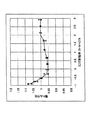
図4に焼付試験結果を示す。横軸には「逃げ余裕率」(h−b−c)/bを、縦軸には焼付時間を(h−b−c)/b>2の軸受の平均焼付時間で除した値(焼付時間比)を表している。焼付時間比算出の基準として、(h−b−c)/b>2の軸受を選んだ理由は、従来の軸受がエッジロードを避けるため、逃げ寸法cを小さくしていたことから、殆どの軸受は、(h−b−c)/b>2となっていたためである。
【0034】
図4から、耐焼付性は、(h−b−c)/bが負、すなわち、接触楕円が鍔逃げに干渉しても、−0.6程度までならば、低下せずに、むしろ向上していることが分かる。この理由として、接触楕円が鍔逃げに干渉した際、鍔逃げに溜まっている潤滑油が接触面に入り込みやすく、接触点を潤滑し易くなる。そのため、接触楕円に鍔逃げが干渉してエッジロード発生により多少面圧が上昇するにもかかわらず、耐焼付性を低下させることがない、と考えられる。従来、接触楕円が鍔逃げに干渉するとエッジロードが発生して、焼付き易くなると考えられていたため、逃げ寸法cは、その加工が難しいにもかかわらず十分小さく加工されていた。しかし、本試験の結果から、実際には、接触楕円が鍔逃げにある程度干渉しても耐焼付性が低下しないばかりか、むしろ向上することが分かり、耐焼付性だけに着目すれば、逃げ寸法cを従来のものよりも大きくできることが明らかになった。
【0035】
さらに、図4から、「逃げ余裕率」が正の範囲においても、従来の軸受よりも小さい「逃げ余裕率」2以下の範囲において、耐焼付性が向上している。この理由としても、接触楕円が鍔逃げに接近するにつれて、鍔逃げに溜まっている潤滑油が接触面に入り込みやすく、接触点の潤滑性が向上するためと考えられる。
【0036】
(2)軸受トルク測定試験
次に、(1)の耐焼付性評価と同様に、鍔逃げ(逃げ寸法c)の異なる円錐ころ軸受を用い、軸受トルク評価を行った。さらに、接点高さhの異なる円錐ころ軸受でも軸受トルク評価を行った。軸受トルクは、図10に示す試験装置を用いて、供試軸受部に試験軸受を組み込み、50℃、500ml/minの循環給油、一定アキシャル荷重(Fa/C0r=0.035,0.106,0.179)、一定回転数の条件で測定した。潤滑油は焼付試験潤滑油と同一である。
【0037】
図5、図6、図7に鍔逃げ(逃げ寸法c)の異なる円錐ころ軸受を用いた動トルク試験結果を示す。横軸には「逃げ余裕率」(h−b−c)/bを、縦軸には「逃げ余裕率」が2を超える軸受の平均値を基準とした動トルク比を表している。
【0038】
図5、図6、図7より、(h−b−c)/b<−0.6になると、動トルクは増加する。従って、軸受の低トルク性を低下させない範囲としては、−0.6≦(h−b−c)/bを満たす必要があることが分かる。
【0039】
図5より、−0.6≦(h−b−c)/b≦2の範囲で低トルク性が向上することが分かる。図6では、−0.6≦(h−b−c)/b≦1の範囲で低トルク性が向上することが分かる。さらに、図7より、−0.6≦(h−b−c)/b≦0の範囲で低トルク性が向上することが分かる。
【0040】
また、図8に、接点高さhの異なる円錐ころ軸受(逃げ寸法cは一定)を用いた動トルク試験結果を示す。試験条件は、50℃、500ml/minの循環給油、一定アキシャル荷重(Fa/C0r=0.106,)、一定回転数である。横軸には「逃げ余裕率」(h−b−c)/bを、縦軸には図5,6,7で用いた(h−b−c)/b≒2.3の軸受の結果を基準とした動トルク比を表している。
【0041】
図8より、動トルクは、−0.6≦(h−b−c)/bで低下するが、2.5<(h−b−c)/bで増加する。これは、接点高さが増加しすぎると、接点のすべり摩擦に起因するトルク成分が増加して、動トルクが増加するためである。従って、軸受の低トルク性を低下させない範囲としては、−0.6≦(h−b−c)/b≦2.5を満たす必要があることが分かる。
【0042】
(3)鍔逃げの加工性
鍔逃げ(逃げ寸法c)を極限まで小さく加工できれば、(h−b−c)/bの上限は大きくすることが可能であるが、鍔逃げ(逃げ寸法c)を小さく加工することは、従来の技術で説明したように、限界がある。
【0043】
現状の水準でコストや生産性を低下させることなしに加工できる逃げ寸法cは、0.3〜1.0mm程度である。この値は、軸受サイズが大きくなると若干大きくなるが、ほぼこの範囲に入っている。これに対し、軸受サイズは径が大きくなると接点高さhが大きくなるので、(h−b−c)/bは大きくなる傾向にあり、最大5程度になる。なお、軸受サイズが小さな軸受については、接触楕円の干渉を避けるため鍔逃げを上記最適寸法の0.3より小さな逃げとして、ばらつきがあって接触楕円の端と逃げの距離が小さい場合でも干渉しないような公差を選択しているので、実際にでき上がった軸受は前述のように(h−b−c)/bは2を超えるものがほとんどで、現行の軸受の(h−b−c)/bは2〜5の間に入っている。
【0044】
これに対し、本発明では、(h−b−c)/bを小さくして積極的に鍔逃げが接触楕円と干渉する方向に寸法をシフトさせ潤滑油の保持効果により耐焼付性を向上させることができる。逃げが接触楕円と干渉して良いことになれば、逃げを必要以上に小さくする必要がなく、加工性に適した逃げ寸法を選択することができる。
【0045】
なお、本発明は、上述した発明の実施の形態および実施例に限定されないのは勿論であり、種々変形可能である。例えば、円錐ころ軸受を例に説明したが、本発明は、これに限定されず、鍔部を有するころ軸受、例えば、円筒ころ軸受、球面ころ軸受などころ軸受の全てに適用できる。
【0046】
また、上記発明の実施の形態および実施例では、1種類の軸受の実験によるデータを基に行っているが、軸受の焼付およびトルクのメカニズムから、潤滑油の枯渇および低トルクに適する余裕率−0.6≦(h−b−c)/b<0の範囲は、潤滑油の保持効果および接触の関係から軸受のサイズに関係無く適用可能である。
【0047】
【発明の効果】
以上説明したように、本発明によれば、接触楕円の「逃げ余裕率」が上記範囲であり、鍔部の「逃げ寸法」の最適範囲を得ているため、耐焼付性能や低トルク性能の低下を招来することなく、鍔部の「逃げ寸法」をある程度大きくすることができる。すなわち、このように「逃げ寸法」の最適化を図ることにより、軸受性能を向上すると同時に、鍔部の逃げ溝の加工性を向上してコストを低減している。
【0048】
また、「逃げ余裕率」は、荷重条件が不明の場合でも、上記(1)〜(14)式を用いることにより、全て軸受内部諸元より容易に計算可能である。即ち、軸受の部品の内部寸法を測定すれば、計算することができる。
【図面の簡単な説明】
【図1】円錐ころ軸受のころと鍔部との接触状態を示す模式的断面図。
【図2】円錐ころ軸受のころと鍔部との接触状態を拡大して示す拡大模式図。
【図3】(a)は、接触楕円が鍔逃げ(逃げ寸法c)に干渉していない状態を示す模式図であり、(b)は、接触楕円が鍔逃げ(逃げ寸法c)に干渉している状態を示す模式図。
【図4】焼付試験結果を示すグラフ。
【図5】動トルク測定結果(Fa/C0r=0.035)を示すグラフ。
【図6】動トルク測定結果(Fa/C0r=0.106)を示すグラフ。
【図7】動トルク測定結果(Fa/C0r=0.179)を示すグラフ。
【図8】動トルク測定結果(接点高さhを変化させた場合)を示すグラフ。
【図9】焼付試験装置の模式図。
【図10】軸受トルク試験装置の模式図。
【図11】円錐ころ軸受の内輪、外輪、およびころの角度を示す模式的断面図。
【図12】円錐ころ軸受の模式的断面図。
【図13】本発明の第2実施の形態に係り、ころ軸受の断面図および要部拡大図。
【図14】本発明の第2実施の形態の変形例に係り、ころ軸受の断面図および要部拡大図。
【符号の説明】
1 外輪
2 内輪
3 円錐ころ
4 鍔部
5 逃げ溝
c 鍔部側の研削逃げ寸法
h 鍔部ところの端面との接触点高さ
b 鍔部ところの端面との接触により形成される接触楕円の短半径
11 内輪
12 軌道面
13 鍔部
14 逃げ溝
15 微小孔
16 含油性の多孔質材(または樹脂)[0001]
BACKGROUND OF THE INVENTION
The present invention improves the bearing performance such as anti-seizure performance and low torque performance by obtaining the optimum range of the flange clearance dimension, and at the same time improves the workability of the flange clearance groove and reduces the cost. Related to bearings.
[0002]
[Prior art]
In the tapered roller bearing, as shown in FIG. 1, a
[0003]
The axial load acting on the tapered roller bearing is mainly supported by the
[0004]
Since the contact between the
[0005]
By the way, when grinding the raceway surfaces of the inner and
[0006]
Therefore, conventionally, the “relief dimension c (FIG. 1)” of the “
[0007]
[Problems to be solved by the invention]
However, it is extremely difficult to process the “
a. In order to secure the strength and rigidity of the cutting tool for forming the “
b. It is necessary to ensure the oscillation width of the grinding wheel.
c. It is necessary to prevent grinding defects such as grinding residue and high height during grinding.
d. It is necessary to allow variations in the finish dimensions of each part.
e. There is a limit to the priority management of processing dimensions due to the balance between production cycle and cost.
f. It is necessary to prevent sagging of the grindstone due to heat treatment deformation or the like.
[0008]
In particular, in a small-diameter bearing for automobiles or the like, the contact point height (h in FIG. 1) between the
[0009]
For this reason, the “relief dimension c” is increased to some extent without deteriorating the seizure resistance performance and low torque performance of the bearing, thereby facilitating the processing of the “
[0010]
The present invention has been made in view of the circumstances as described above, and by obtaining the optimum range of the clearance dimension of the flange portion, bearing performance such as seizure resistance performance and low torque performance is improved, and at the same time, the flange portion An object of the present invention is to provide a roller bearing that can improve the workability of the relief groove and reduce the cost.
[0011]
[Means for Solving the Problems]
In order to achieve the above object, a roller bearing according to the present invention is a roller bearing in which a plurality of rollers are interposed between an outer ring and an inner ring so as to be able to roll, and a flange is formed on a side portion of the outer ring or the inner ring. In
The chamfer side grinding clearance dimension is c, the height of the contact point with the end face at the heel part is h, and the short radius of the contact ellipse formed by the contact with the end face at the buttock is b, When Fa is a bearing axial load and C 0r is a basic static load rating of the bearing,
Under the condition of Fa / C 0r = 0.179 ,
The clearance margin rate of the contact ellipse formed by contact with the end face of the buttocks is
−0.6 ≦ (h−b−c) / b <0
And
The grinding clearance dimension c is 0.3 to 1.0 mm.
[0012]
As described above, according to the present invention, the clearance margin ratio of the contact ellipse is in the above range, and the optimum range of the “flank dimension” of the collar portion is obtained, resulting in a decrease in seizure resistance performance and low torque performance. Without any problem, the “flank dimension” of the buttocks can be increased to some extent. That is, by optimizing the “relief dimension” in this way, the bearing performance is improved, and at the same time, the workability of the relief groove of the flange portion is improved and the cost is reduced.
[0013]
DETAILED DESCRIPTION OF THE INVENTION
Hereinafter, a roller bearing according to an embodiment of the present invention will be described with reference to the drawings.
(First embodiment)
In the first embodiment of the present invention, as shown in FIG. 2, the grinding relief dimension (mm, hereinafter referred to as relief dimension or saddle relief) on the
[0014]
Here, the elliptical short radius b is defined by the following equation. The sources of the following formulas (1) to (7) are Ball Bearing Lubrication (author: Hamrock & Dowson, pages 54 to 76, John Wiley, 1981, 1st edition), and the following (8) to (8) The source of the formula 14) is rolling bearing engineering (rolling bearing engineering editorial committee edition, pages 193 to 195, Yokendo, 1975, first edition).
[0015]
[Expression 1]
[Expression 2]
Hereinafter, a tapered roller bearing will be described as an example. As shown in FIGS. 3 (a) and 3 (b), (hbc) shows the state of interference of the contact ellipse with the saddle escape (relief dimension c). Depending on whether this parameter is positive or negative, the contact state is as follows.
[0018]
(A) hbc> 0: The contact ellipse does not interfere with the wrinkle escape (state shown in FIG. 3A)
(B) hbc- <0: A part of the contact ellipse interferes with wrinkle escape (state shown in FIG. 3B).
[0019]
The value obtained by dividing the above parameter by the contact ellipse short radius b is the “escape margin rate” of the contact ellipse as described above. This “escape margin rate” is a value representing the interference state between the ellipse and the heel escape by the ratio of the short radius of the contact ellipse, and is a representative parameter of the interference state.
[0020]
here,
(A) (hbc) / b> 0: No interference with the flank of the contact ellipse (state shown in FIG. 3A)
(B) (hbc) / b = 0: The edge of the contact ellipse coincides with the edge of the flange escape (c) (hbc) / b <0: The contact ellipse interferes with the flange escape A state where a part of the contact ellipse protrudes into the heel escape (state shown in FIG. 3B).
[0021]
Here, b is a value that varies depending on the load, and “escape margin ratio” (hbc) / b also varies depending on the load. The larger b is, that is, the larger the load is, the closer the heel escape (relief dimension c) and the contact ellipse approach, and the more severe the interference between them.
[0022]
When the load can be specified, b calculated from the load may be used. However, when the load condition is unknown, the “escape margin ratio” represents the most severe state when evaluated by the maximum value of b. Because it is possible, it is convenient. Therefore, when the operating load condition was investigated for a general application of the roller bearing of the present embodiment, it was found that it was 25% or less of C 0r (basic static load rating of the bearing) in many cases. Accordingly, since the maximum load value may be 25% of C 0r , the contact ellipse short radius b can be obtained using the above equations (1) to (14) including the equation (9) as described above. .
[0023]
From the above, even when the load condition is unknown, the “relief margin rate” can be easily calculated from the internal dimensions of the bearing by using the above equations (1) to (14). That is, it can be calculated by measuring the internal dimensions of the bearing components.
[0024]
In the present embodiment, bearings with different saddle escapes (relief dimension c) and bearings with different contact heights h are prototyped, and (hbc) / b is variously changed to improve seizure resistance, An evaluation test was conducted focusing on the bearing performance of torque. Based on these results, the optimum range of (hbc) / b was determined, and as a result, the optimum range was found. This will be described in the section “Example” described later.
(Second Embodiment)
In tapered roller bearings and cylindrical roller bearings, the end surface of the flange is rolling-sliding contact with a large slip, and the friction and wear are larger than the rolling friction. Problems such as seizure may occur.
[0025]
As a countermeasure for avoiding this seizure, JP-A-9-250547 and JP-A-10-89352 disclose a method of supplying a large amount of lubricating oil to the collar portion by changing the flow of the lubricating oil in the bearing, Japanese Patent Application Laid-Open Nos. 7-91452 and 7-103243 disclose methods for devising the surface shape of the collar and the roller end surface, and Japanese Patent Application Laid-Open Nos. 9-177774 and 9-287616 are based on coatings. JP-A-8-135666 and JP-A-9-32859 disclose a method of surface modification, which discloses a method of providing an oil sump for temporarily storing lubricating oil in the vicinity of the bearing. Japanese Patent Laid-Open No. 210472 and Japanese Patent Laid-Open No. 9-105450 disclose a method of providing a shield plate or the like on the bearing end surface so that lubricating oil is temporarily accumulated in the bearing. To have.
[0026]
However, the countermeasures against seizure disclosed in these publications are not always sufficient, and there are cases where it is desired to further improve seizure resistance.
[0027]
For this reason, in the second embodiment, in a raceway ring having a tapered roller bearing or a cylindrical roller bearing flange, a grinding groove between the raceway surface and the flange is generally used. By providing a plurality of micro holes in the radial direction, or by filling the micro holes with an oil-containing porous material or resin, lubricating oil is retained in the micro holes, and centrifugal force is applied when the lubricating oil is insufficient. The lubricant is oozed out to prevent seizure, thereby improving seizure resistance.
[0028]
Specifically, as shown in FIG. 13, in the tapered roller bearing, a plurality of radial micro-holes 15 are provided in a grinding
[0029]
Further, as shown in FIG. 14, in the tapered roller bearing, a plurality of radial micro-holes 15 are formed in the
[0030]
In addition, the same effect can be acquired also about a cylindrical roller bearing if this invention is applied to the escape groove of a rotating wheel. As a matter of course, these holes can be processed more easily if they can be processed with a large clearance .
[0031]
【Example】
Hereinafter, examples of the roller bearing according to the first embodiment of the present invention will be described.
[0032]
(1) Evaluation of seizure resistance Trial tapered roller bearings having different flank clearances (relief dimension c) were made to evaluate seizure resistance. The tapered roller bearing has an inner diameter of 30 mm, an outer diameter of 70 mm, and a basic static load rating C 0r = 5700 kgf. Evaluation of seizure resistance was performed by incorporating a test bearing into the test bearing portion using the test apparatus shown in FIG. The seizure resistance was evaluated by the time (seizure time) from when the oil supply was cut off until the dynamic torque of the bearing increased rapidly and seized. The lubrication conditions for circulating oil supply are an oil supply amount of 1000 ml / min and an oil temperature of 50 ° C. The test was performed under a constant axial load and a constant rotation speed.
[0033]
FIG. 4 shows the seizure test results. The horizontal axis represents the “relief margin ratio” (hbc) / b, and the vertical axis represents the seizure time divided by the average seizure time of the bearing (hbc) / b> 2. Time ratio). The reason why the bearing of (hbc) / b> 2 was selected as the basis for calculating the baking time ratio was that the conventional bearing had a small relief dimension c in order to avoid edge loading. This is because the bearing was (hbc) / b> 2.
[0034]
From FIG. 4, the seizure resistance is improved without (decreasing) if (hbc) / b is negative, that is, even if the contact ellipse interferes with wrinkle escape, it does not decrease. You can see that The reason for this is that when the contact ellipse interferes with the scissors escape, the lubricating oil accumulated in the scissors escape easily enters the contact surface, and the contact points are easily lubricated. For this reason, it is considered that seizure resistance does not deteriorate even though the contact ellipse interferes with the contact ellipse and the surface pressure slightly increases due to the occurrence of edge loading. Conventionally, it has been considered that when the contact ellipse interferes with the wrinkle escape, an edge load is generated and seizure is likely to occur, so that the escape dimension c is machined sufficiently small although the machining is difficult. However, from the results of this test, it can be seen that, even if the contact ellipse interferes with the wrinkle relief to some extent, the seizure resistance is not reduced, but rather improved. It became clear that c can be made larger than the conventional one.
[0035]
Further, from FIG. 4, even when the “relief margin ratio” is in a positive range, the seizure resistance is improved in a range of “relief margin ratio” 2 or less, which is smaller than that of the conventional bearing. The reason for this is also considered that as the contact ellipse approaches the heel escape, the lubricating oil accumulated in the heel escape easily enters the contact surface, and the lubricity at the contact point is improved.
[0036]
(2) Bearing torque measurement test Next, as in the seizure resistance evaluation of (1), a bearing torque evaluation was performed using tapered roller bearings having different flange clearances (relief dimensions c). Furthermore, bearing torque evaluation was also performed on tapered roller bearings with different contact heights h. The test torque shown in FIG. 10 was used to incorporate the test bearing into the test bearing section, and 50 ° C., 500 ml / min circulating oil supply, constant axial load (F a / C 0r = 0.035,0. 106, 0.179), and the measurement was performed under the condition of a constant rotational speed. The lubricant is the same as the seizure test lubricant.
[0037]
FIG. 5, FIG. 6, and FIG. 7 show the results of dynamic torque tests using tapered roller bearings having different flange clearances (relief dimensions c). The abscissa represents the “relief margin ratio” (hbc) / b, and the ordinate represents the dynamic torque ratio based on the average value of the bearings whose “relief margin ratio” exceeds 2.
[0038]
5, 6, and 7, the dynamic torque increases when (hbc) / b <−0.6. Therefore, it is understood that −0.6 ≦ (hbc) / b needs to be satisfied as a range in which the low torque property of the bearing is not lowered.
[0039]
FIG. 5 shows that the low torque property is improved in the range of −0.6 ≦ (hbc) / b ≦ 2. In FIG. 6, it can be seen that the low torque property is improved in the range of −0.6 ≦ (hbc) / b ≦ 1. Furthermore, it can be seen from FIG. 7 that the low torque property is improved in the range of −0.6 ≦ (hbc) / b ≦ 0.
[0040]
FIG. 8 shows the results of a dynamic torque test using tapered roller bearings with different contact heights h (relief dimension c is constant). The test conditions are 50 ° C., 500 ml / min circulating oil supply, constant axial load (F a / C 0r = 0.106), and constant rotation speed. The result of the bearing of (hbc) /b≈2.3 used in FIGS. 5, 6, and 7 on the horizontal axis “escape margin ratio” (hbc) / b, and the vertical axis. Represents the dynamic torque ratio with reference to.
[0041]
From FIG. 8, the dynamic torque decreases with −0.6 ≦ (hbc) / b, but increases with 2.5 <(hbc) / b. This is because, if the contact height increases too much, the torque component due to the sliding friction of the contact increases and the dynamic torque increases. Therefore, it is understood that −0.6 ≦ (hbc) /b≦2.5 must be satisfied as a range in which the low torque property of the bearing is not lowered.
[0042]
(3) Workability of reed relief If the relief (relief dimension c) can be machined as small as possible, the upper limit of (hbc) / b can be increased. As described in the prior art, there is a limit to processing a small size.
[0043]
The clearance dimension c that can be processed without reducing the cost and productivity at the current level is about 0.3 to 1.0 mm. This value increases slightly as the bearing size increases, but is approximately within this range. On the other hand, as the bearing size increases, the contact height h increases as the diameter increases, so (hbc) / b tends to increase and is about 5 at the maximum. For bearings with a small bearing size, in order to avoid interference of the contact ellipse, 鍔 escape is assumed to be less than 0.3 of the above optimum dimension, and even when there is a variation and the distance between the end of the contact ellipse and the escape is small, there is no interference As described above, most of the actually completed bearings have (hbc) / b exceeding 2 as described above, and (hbc) / b of current bearings. b is between 2 and 5.
[0044]
On the other hand, in the present invention, by reducing (hbc) / b, the size is positively shifted in the direction in which the saddle escape interferes with the contact ellipse, and the seizure resistance is improved by the retaining effect of the lubricating oil. be able to. If the relief can interfere with the contact ellipse, it is not necessary to make the relief smaller than necessary, and a relief dimension suitable for workability can be selected.
[0045]
The present invention is not limited to the above-described embodiments and examples, and can be variously modified. For example, although a tapered roller bearing has been described as an example, the present invention is not limited to this, and can be applied to all roller bearings having a flange, such as a cylindrical roller bearing and a spherical roller bearing.
[0046]
Further, in the embodiments and examples of the invention, one is performed based on data from experiments of the bearing, the mechanism of seizure and torque of the bearing, allowance ratio suitable for the depletion and low torque of the lubricant - The range of 0.6 ≦ (hbc) / b <0 is applicable regardless of the size of the bearing due to the retention effect of the lubricating oil and the contact relationship.
[0047]
【The invention's effect】
As described above, according to the present invention, the “relief margin ratio” of the contact ellipse is in the above range, and the optimum range of the “relief dimension” of the collar portion is obtained. The “relief dimension” of the buttocks can be increased to some extent without causing a decrease. That is, by optimizing the “relief dimension” in this way, the bearing performance is improved, and at the same time, the workability of the relief groove of the flange portion is improved, thereby reducing the cost.
[0048]
Further, the “relief margin ratio” can be easily calculated from the internal dimensions of the bearing by using the above equations (1) to (14) even when the load condition is unknown. That is, it can be calculated by measuring the internal dimensions of the bearing components.
[Brief description of the drawings]
FIG. 1 is a schematic cross-sectional view showing a contact state between a roller and a flange of a tapered roller bearing.
FIG. 2 is an enlarged schematic view showing a contact state between a roller and a flange portion of a tapered roller bearing in an enlarged manner.
FIG. 3A is a schematic diagram showing a state where the contact ellipse does not interfere with the saddle escape (relief dimension c), and FIG. 3B is a schematic diagram showing that the contact ellipse interferes with the saddle escape (relief dimension c). The schematic diagram which shows the state.
FIG. 4 is a graph showing a seizure test result.
FIG. 5 is a graph showing dynamic torque measurement results (F a / C 0r = 0.035).
FIG. 6 is a graph showing dynamic torque measurement results (F a / C 0r = 0.106).
FIG. 7 is a graph showing dynamic torque measurement results (F a / C 0r = 0.179).
FIG. 8 is a graph showing dynamic torque measurement results (when the contact height h is changed).
FIG. 9 is a schematic diagram of a seizure test apparatus.
FIG. 10 is a schematic diagram of a bearing torque test apparatus.
FIG. 11 is a schematic cross-sectional view showing angles of an inner ring, an outer ring, and rollers of a tapered roller bearing.
FIG. 12 is a schematic cross-sectional view of a tapered roller bearing.
FIG. 13 is a cross-sectional view and an enlarged view of a main part of a roller bearing according to a second embodiment of the present invention.
FIG. 14 is a sectional view and an enlarged view of a main part of a roller bearing according to a modification of the second embodiment of the present invention.
[Explanation of symbols]
DESCRIPTION OF
Claims (2)
鍔部側の研削逃げ寸法を、cとし、鍔部ところの端面との接触点高さを、hとし、鍔部ところの端面との接触により形成される接触楕円の短半径を、bとし、且つFaを軸受アキシャル荷重、C0rを軸受の基本静定格荷重としたとき、
Fa/C0r=0.179の条件下で、
鍔部ところの端面との接触により形成される接触楕円の逃げ余裕率が、
−0.6≦(h−b−c)/b<0
であり、
前記研削逃げ寸法cは0.3〜1.0mmであることを特徴とするころ軸受。In a roller bearing in which a plurality of rollers are rotatably mounted between an outer ring and an inner ring, and a flange is formed on the side of the outer ring or the inner ring.
The chamfer side grinding clearance dimension is c, the height of the contact point with the end face at the heel part is h, and the short radius of the contact ellipse formed by contact with the end face at the heel part is b. When Fa is a bearing axial load and C 0r is a basic static load rating of the bearing,
Under the condition of Fa / C 0r = 0.179 ,
The clearance margin rate of the contact ellipse formed by contact with the end face of the buttocks is
−0.6 ≦ (h−b−c) / b <0
And
The roller bearing characterized in that the grinding clearance dimension c is 0.3 to 1.0 mm.
Priority Applications (3)
| Application Number | Priority Date | Filing Date | Title |
|---|---|---|---|
| JP20364799A JP4399905B2 (en) | 1999-07-16 | 1999-07-16 | Roller bearing |
| GB0017269A GB2352010B (en) | 1999-07-16 | 2000-07-13 | Roller bearing |
| US09/617,921 US6379049B1 (en) | 1999-07-16 | 2000-07-17 | Rolling bearing |
Applications Claiming Priority (1)
| Application Number | Priority Date | Filing Date | Title |
|---|---|---|---|
| JP20364799A JP4399905B2 (en) | 1999-07-16 | 1999-07-16 | Roller bearing |
Publications (3)
| Publication Number | Publication Date |
|---|---|
| JP2001032843A JP2001032843A (en) | 2001-02-06 |
| JP2001032843A5 JP2001032843A5 (en) | 2006-09-14 |
| JP4399905B2 true JP4399905B2 (en) | 2010-01-20 |
Family
ID=16477518
Family Applications (1)
| Application Number | Title | Priority Date | Filing Date |
|---|---|---|---|
| JP20364799A Expired - Lifetime JP4399905B2 (en) | 1999-07-16 | 1999-07-16 | Roller bearing |
Country Status (3)
| Country | Link |
|---|---|
| US (1) | US6379049B1 (en) |
| JP (1) | JP4399905B2 (en) |
| GB (1) | GB2352010B (en) |
Families Citing this family (24)
| Publication number | Priority date | Publication date | Assignee | Title |
|---|---|---|---|---|
| US6502996B2 (en) * | 2001-05-11 | 2003-01-07 | The Timken Company | Bearing with low wear and low power loss characteristics |
| JP2004251323A (en) * | 2003-02-18 | 2004-09-09 | Ntn Corp | Cylindrical roller bearing |
| EP1471271A3 (en) * | 2003-04-25 | 2005-11-30 | Koyo Seiko Co., Ltd. | Tapered roller bearing and final reduction gear |
| JP2005076674A (en) * | 2003-08-28 | 2005-03-24 | Ntn Corp | Tapered roller bearing for transmission of automobile |
| JP2006090516A (en) * | 2004-09-27 | 2006-04-06 | Ntn Corp | Cylindrical roller bearing |
| JP2006177441A (en) * | 2004-12-22 | 2006-07-06 | Jtekt Corp | Pinion shaft support device for vehicle |
| DE102005061179A1 (en) * | 2005-12-21 | 2007-06-28 | Schaeffler Kg | Production of a bearing ring for a rolling body comprises forming the final contour of the ring by hard turning |
| FR2925631A1 (en) * | 2007-12-21 | 2009-06-26 | Snr Roulements Sa | Conical roller bearing assembly for gear box, has rollers with small and large end faces that are in contact with contact face of ring's collar, where contact face extends until being intersected with geometry cone defined by cone distance |
| JP2009191986A (en) * | 2008-02-15 | 2009-08-27 | Jtekt Corp | Tapered roller bearing |
| FR2998630B1 (en) * | 2012-11-28 | 2015-02-20 | Ntn Snr Roulements | BEARING BEARING |
| JP2014173686A (en) * | 2013-03-11 | 2014-09-22 | Nsk Ltd | Sealed roll neck bearing |
| JP6326726B2 (en) * | 2013-05-30 | 2018-05-23 | 日本精工株式会社 | Roller bearing |
| CN103352920A (en) * | 2013-07-05 | 2013-10-16 | 新昌县双菱汽车轴承有限公司 | Conical roller bearing |
| JP6323136B2 (en) * | 2014-04-16 | 2018-05-16 | 株式会社ジェイテクト | Roller bearing ring, roller bearing and power transmission device |
| JP6369211B2 (en) * | 2014-08-11 | 2018-08-08 | 株式会社ジェイテクト | Roller bearing |
| JP6350099B2 (en) * | 2014-08-11 | 2018-07-04 | 株式会社ジェイテクト | Tapered roller bearing |
| JP6492646B2 (en) * | 2014-12-26 | 2019-04-03 | 株式会社ジェイテクト | Tapered roller bearing |
| JP6895286B2 (en) * | 2017-03-24 | 2021-06-30 | Ntn株式会社 | Bearing device for wheels |
| US11002310B2 (en) * | 2019-01-11 | 2021-05-11 | Aktiebolaget Skf | Rolling-element bearing unit and tapered-roller-bearing inner ring |
| DE112020004434T5 (en) * | 2019-09-19 | 2022-06-23 | Ntn Corporation | tapered roller bearing |
| JP7449058B2 (en) * | 2019-09-19 | 2024-03-13 | Ntn株式会社 | tapered roller bearing |
| CN114555959A (en) * | 2019-09-19 | 2022-05-27 | Ntn株式会社 | Tapered roller bearing |
| JP7449059B2 (en) * | 2019-09-19 | 2024-03-13 | Ntn株式会社 | tapered roller bearing |
| JP7339090B2 (en) * | 2019-09-19 | 2023-09-11 | Ntn株式会社 | tapered roller bearing |
Family Cites Families (6)
| Publication number | Priority date | Publication date | Assignee | Title |
|---|---|---|---|---|
| US1784914A (en) * | 1928-12-26 | 1930-12-16 | Bower Roller Bearing Co | Roller bearing |
| US1992682A (en) * | 1931-11-21 | 1935-02-26 | Tyson Roller Bearing Corp | Tapered roller bearing |
| JP3011093B2 (en) * | 1996-04-05 | 2000-02-21 | 日本精工株式会社 | Tapered roller bearings for automobiles |
| US6033123A (en) * | 1997-09-22 | 2000-03-07 | Nsk Ltd. | Tapered roller bearing |
| JPH11190333A (en) * | 1997-09-22 | 1999-07-13 | Nippon Seiko Kk | Conical roller bearing |
| JPH11236920A (en) * | 1998-02-24 | 1999-08-31 | Nippon Seiko Kk | Rolling bearing |
-
1999
- 1999-07-16 JP JP20364799A patent/JP4399905B2/en not_active Expired - Lifetime
-
2000
- 2000-07-13 GB GB0017269A patent/GB2352010B/en not_active Expired - Fee Related
- 2000-07-17 US US09/617,921 patent/US6379049B1/en not_active Expired - Lifetime
Also Published As
| Publication number | Publication date |
|---|---|
| GB2352010B (en) | 2001-05-23 |
| US6379049B1 (en) | 2002-04-30 |
| GB0017269D0 (en) | 2000-08-30 |
| GB2352010A (en) | 2001-01-17 |
| JP2001032843A (en) | 2001-02-06 |
Similar Documents
| Publication | Publication Date | Title |
|---|---|---|
| JP4399905B2 (en) | Roller bearing | |
| US7670058B2 (en) | Cage for antifriction bearings with rollers | |
| US5704718A (en) | Sintered oil-impregnated bearing and method for manufacturing same | |
| CN103737024A (en) | Machining method for rolling bearing with ring precisely shaped by hard finishing | |
| JP2007051715A (en) | Tapered roller bearing, tapered roller bearing device, and vehicular pinion shaft supporting device using it | |
| JP2009197904A (en) | Rolling mechanical element | |
| JP2002048146A (en) | Roller bearing | |
| EP1947356A2 (en) | Cage for rolling bearing and rolling bearing having the same | |
| EP3499064A1 (en) | Ball bearing, ball bearing device, and machine tool | |
| JP6934728B2 (en) | Tapered roller bearing | |
| JP2006009891A (en) | Roller bearing | |
| JPH09291942A (en) | Radial rolling bearing | |
| JP4487530B2 (en) | Roller bearing cage and manufacturing method thereof | |
| JPH0791452A (en) | Rolling bearing | |
| JPH08200376A (en) | Cage for roller bearing | |
| US10197094B2 (en) | Double-row spherical roller bearing | |
| JP4190781B2 (en) | Cylindrical roller bearing | |
| Takemura et al. | Development of a new life equation for ball and roller bearings | |
| JP4366580B2 (en) | Ball bearing cage | |
| JP4322641B2 (en) | Cylindrical roller bearing | |
| JP4322650B2 (en) | Cylindrical roller bearing | |
| JPH07103243A (en) | Rolling bearing | |
| WO2018181524A1 (en) | Retainer for rolling bearing and rolling bearing with outer ring oil supply hole | |
| WO2022209598A1 (en) | Roller bearing, roller bearing unit, motor, roller bearing manufacturing method, and roller bearing silencing method | |
| JP2006349015A (en) | Tapered roller bearing and method of designing the same |
Legal Events
| Date | Code | Title | Description |
|---|---|---|---|
| A621 | Written request for application examination |
Free format text: JAPANESE INTERMEDIATE CODE: A621 Effective date: 20060628 |
|
| A521 | Request for written amendment filed |
Free format text: JAPANESE INTERMEDIATE CODE: A523 Effective date: 20060727 |
|
| A977 | Report on retrieval |
Free format text: JAPANESE INTERMEDIATE CODE: A971007 Effective date: 20080725 |
|
| A131 | Notification of reasons for refusal |
Free format text: JAPANESE INTERMEDIATE CODE: A131 Effective date: 20080805 |
|
| A521 | Request for written amendment filed |
Free format text: JAPANESE INTERMEDIATE CODE: A523 Effective date: 20080926 |
|
| A131 | Notification of reasons for refusal |
Free format text: JAPANESE INTERMEDIATE CODE: A131 Effective date: 20081209 |
|
| A521 | Request for written amendment filed |
Free format text: JAPANESE INTERMEDIATE CODE: A523 Effective date: 20090205 |
|
| A131 | Notification of reasons for refusal |
Free format text: JAPANESE INTERMEDIATE CODE: A131 Effective date: 20090526 |
|
| A521 | Request for written amendment filed |
Free format text: JAPANESE INTERMEDIATE CODE: A523 Effective date: 20090623 |
|
| TRDD | Decision of grant or rejection written | ||
| A01 | Written decision to grant a patent or to grant a registration (utility model) |
Free format text: JAPANESE INTERMEDIATE CODE: A01 Effective date: 20091006 |
|
| A01 | Written decision to grant a patent or to grant a registration (utility model) |
Free format text: JAPANESE INTERMEDIATE CODE: A01 |
|
| R150 | Certificate of patent or registration of utility model |
Free format text: JAPANESE INTERMEDIATE CODE: R150 |
|
| A61 | First payment of annual fees (during grant procedure) |
Free format text: JAPANESE INTERMEDIATE CODE: A61 Effective date: 20091019 |
|
| FPAY | Renewal fee payment (event date is renewal date of database) |
Free format text: PAYMENT UNTIL: 20121106 Year of fee payment: 3 |
|
| FPAY | Renewal fee payment (event date is renewal date of database) |
Free format text: PAYMENT UNTIL: 20121106 Year of fee payment: 3 |
|
| FPAY | Renewal fee payment (event date is renewal date of database) |
Free format text: PAYMENT UNTIL: 20131106 Year of fee payment: 4 |
|
| S801 | Written request for registration of abandonment of right |
Free format text: JAPANESE INTERMEDIATE CODE: R311801 |
|
| ABAN | Cancellation due to abandonment | ||
| R350 | Written notification of registration of transfer |
Free format text: JAPANESE INTERMEDIATE CODE: R350 |