EP1795756A1 - Fixed vane of turbo molecular pump - Google Patents
Fixed vane of turbo molecular pump Download PDFInfo
- Publication number
- EP1795756A1 EP1795756A1 EP05780851A EP05780851A EP1795756A1 EP 1795756 A1 EP1795756 A1 EP 1795756A1 EP 05780851 A EP05780851 A EP 05780851A EP 05780851 A EP05780851 A EP 05780851A EP 1795756 A1 EP1795756 A1 EP 1795756A1
- Authority
- EP
- European Patent Office
- Prior art keywords
- stator vane
- stator
- inner rim
- vane
- rotor
- Prior art date
- Legal status (The legal status is an assumption and is not a legal conclusion. Google has not performed a legal analysis and makes no representation as to the accuracy of the status listed.)
- Granted
Links
Images




Classifications
-
- F—MECHANICAL ENGINEERING; LIGHTING; HEATING; WEAPONS; BLASTING
- F04—POSITIVE - DISPLACEMENT MACHINES FOR LIQUIDS; PUMPS FOR LIQUIDS OR ELASTIC FLUIDS
- F04D—NON-POSITIVE-DISPLACEMENT PUMPS
- F04D19/00—Axial-flow pumps
- F04D19/02—Multi-stage pumps
- F04D19/04—Multi-stage pumps specially adapted to the production of a high vacuum, e.g. molecular pumps
-
- F—MECHANICAL ENGINEERING; LIGHTING; HEATING; WEAPONS; BLASTING
- F04—POSITIVE - DISPLACEMENT MACHINES FOR LIQUIDS; PUMPS FOR LIQUIDS OR ELASTIC FLUIDS
- F04D—NON-POSITIVE-DISPLACEMENT PUMPS
- F04D19/00—Axial-flow pumps
- F04D19/02—Multi-stage pumps
- F04D19/04—Multi-stage pumps specially adapted to the production of a high vacuum, e.g. molecular pumps
- F04D19/042—Turbomolecular vacuum pumps
-
- F—MECHANICAL ENGINEERING; LIGHTING; HEATING; WEAPONS; BLASTING
- F04—POSITIVE - DISPLACEMENT MACHINES FOR LIQUIDS; PUMPS FOR LIQUIDS OR ELASTIC FLUIDS
- F04D—NON-POSITIVE-DISPLACEMENT PUMPS
- F04D29/00—Details, component parts, or accessories
- F04D29/40—Casings; Connections of working fluid
- F04D29/52—Casings; Connections of working fluid for axial pumps
- F04D29/54—Fluid-guiding means, e.g. diffusers
- F04D29/541—Specially adapted for elastic fluid pumps
- F04D29/542—Bladed diffusers
Definitions
- the present invention relates to a stator vane of a turbo molecular pump and particularly to reduction of breakage of the stator vane.
- Avacuumpump has, in general, a rotor rotatably installed inside a pump case and by high-speed rotation of this rotor, rotor vanes integrally cut out in a number of stages around the rotor are also rotated at a high speed.
- stator vanes and the rotor vanes are alternately arranged in a number of stages.
- the gas molecule on the gas inlet side is sequentially transferred to the inside of a screw stator below a rotor and exhausted, by which the inside of the process chamber or the like of the semiconductor device is made vacuum.
- An interval between the stator vane and the rotor vane performing the above exhaust operation of the gas molecule is set extremely small so that the gas molecule can be exhausted efficiently.
- the stator vane is arranged radial in plural between an inner rim portion 32 and an outer rim portion 33 as shown in Figure 7A, for example, and arranged in a vacuum pump as a stator vane B in the integrally connected state. Also, the stator vane B is generally positioned and fixed in many stages alternately with the rotor vane through a spacer on the inner circumference of the pump case by holding the outer rim portion 33.
- stator vanes B are arranged alternately with the rotor vanes in many stages, and the stator vane shape is a ring and the rotor vanes are integrally cut out in many stages around the rotor.
- the stator vane shape is a ring and the rotor vanes are integrally cut out in many stages around the rotor.
- this type of stator vane B is in a construction that two stator vane halves 30, provided respectively with an inner rimportion 32, the outer rimportion 33, andaplurality of stator blades 31, 31 arranged radial between the inner rim portion 32 and the outer rim portion 33 as shown in Figure 7B, are abutted to each other by a method as shown in Figures 7A and 7B to have the ring state. And the stator vane halves 30 are inserted respectively from both sides with the rotor between them and arranged in the vacuum pump alternately with the rotor vane by being combined in the ring state in the above method.
- an inner rim end 32a and an outer rim end 33a are to be positioned in the ring shape. Since the rotor vane is integrally cut out as mentioned above and the outer rimportion 33 of the stator vane half 30 is positioned and stacked through the spacer, the abutted state of the inner rim end 32a can not be checked from the outside.
- the positioning is carried out only by the outer rim end 33a capable of being visually checked from the outside, while the inner rim end 32a is positioned and arranged without visual check in general.
- This stator vane half 30 in the same semi-ring shape is manufactured in plural from the viewpoint of cost reduction, work efficiency and the like using a punching press or the like (Patent Document 1).
- stator vane half 30 when the two stator vane halves 30 are abutted to each other as in Figure 7A, the inner rim end 32 and the outer rim end 33a of each of the stator vane half 30 should be also abutted to each other and positioned on an abutment line L.
- manufactured stator vane half 30 and the inner rim end 32a might be formed longer in the circumferential direction than a design dimension with respect to the abutment line L at the punching press.
- the interval between the stator blade 31 and the rotor vane is set extremely small as mentioned above.
- the overlap or warping as shown in Figures 9A and 9B occurs in the inner rim end 32a, the interval is further narrowed, and the overlapping or warped portion might contact the rotor vane and result in breakage of the stator blade 31 in the end.
- Patent Document 1 Japanese Patent Laid-Open No. 2003-269365
- Patent Document 2 Japanese Patent Laid-OpenNo. 5-157090
- the present invention was made in order to solve the above problem and has an object to provide a stator vane of a turbo molecular pump suitable for reduction of breakage in a stator vane.
- the present invention is a stator vane of a turbo molecular pump formed annular by abutting a pair of stator vane halves, each having a plurality of stator blades arranged radial and connected integrally by an inner rim portion and an outer rim portion, the stator vane having a gap at the abutment portion of the inner rim portion.
- This stator vane half is manufactured in plural as the same semi-ring shape through profile punching, slit cutting, and bending, for example, and the ring-shaped turbo molecular stator vane is constructed by abutting these two stator vane halves to each other.
- stator vane half since one end of an inner rim end of this stator vane half is formed shorter in the circumferential direction from an abutment line, the inner rim ends do not collide with each other when the two stator vane halves are abutted to each other, and a gap is formed in the inner rim portion of the ring-shaped stator vane formed by abutting these two stator vane halves.
- the gap may be 0.3 mm to 0.7 mm. This gap needs to be an interval to such an extent that the inner rim ends do not overlap or are warped at an abutment portion when the two stator vane halves are abutted and the gap is more preferably 0.5 mm.
- this gap is formed by making one end of the inner rim end of the stator vane half shorter in the circumferential direction from the abutment line formed by abutting the two stator vane halves, and this inner rim end may be an end on the cut-and-raised side of the inner rim portion.
- the construction that the gap is formed in the inner rim portion in the state that the two stator vane halves are abutted together since occurrence of the overlap or warping in the inner rim portion can be prevented when the stator vane is arranged in the vacuum pump, breakage of the stator vane can be prevented, and the stator vane which can reduce breakage of the stator vane can be obtained.
- a vacuum pump shown in Figure 1 is used as a part of a vacuum device in a semiconductor manufacturing apparatus or a liquid-crystal display panel manufacturing apparatus so as to bring a pressure in a vacuum chamber to a predetermined vacuum degree.
- the vacuum pump in the same figure is a complex-type vacuum pump in which a turbo molecular pump and a screw groove pump are combined and constructed to have a rotor 9 rotatably arranged in a cylindrical pump case 1, in which a substantially upper half of the rotor 9 functions as a turbo molecular pump, while the substantially lower half of the rotor 9 functions as a screw groove pump.
- This pump case 1 is in a cylindrical case structure with a bottom having an opening on its upper face as a gas inlet 2 and an exhaust pipe as a gas outlet 3 is projected on one side at the lower part. Also, the bottom part of the pump case 1 is covered by an end plate 4 and at the center on the inner bottom face, a stator column 5 is provided.
- a rotor shaft 7 is rotatably provided, and this rotor shaft 7 is supported by magnetic bearings made from a radial electromagnet 6-1 and an axial electromagnet 6-2 provided in the stator column 5 in the axial direction and the radial direction, respectively.
- a driving motor 8 is arranged inside the stator column 5, and this driving motor 8 is constructed to have a stator 8a in the stator column 5 and a rotor 8b arranged at the rotor shaft 7 so that the rotor shaft 7 is rotated around the shaft.
- the rotor 9 Inside the pump case 1, to an upper projecting end from the stator column 5 of the rotor shaft 7, the rotor 9 with a sectional shape covering the outer periphery of the stator column 5 is connected.
- rotor vanes 10 are arranged and fixed in many stages, and stator blades 31 are arranged and fixed in many stages alternately with the rotor vanes 10.
- a gap between the stator blades 31 in each stage is set at a predetermined distance and positioned and fixed in the cylindrical radial direction of the pump case 1.
- Gap setting and radial positioning of the stator blade 31 in each stage are performed by a ring-shaped spacer 60 stacked in many stages on the inner circumference side of the pump case 1.
- This spacer 60 is constructed so that the upper and the lower spacers 60, 60 are fitted to each other in the state where the spacers 60 are stacked in stages in order to prevent lateral displacement of the spacer 60 in spacer stacking work in a pump assembling process and to enable positioning of the upper and the lower spacers 60, 60 in the cylindrical radial direction of the pump case 1 in the same way.
- step portions 61a, 61b are formed on both the inner and the outer circumferential faces of each spacer 60, and the step portion 61a on the upper inner circumferential face and the step portion 61b on the lower outer circumferential face are fitted with each other.
- the rotor vane 10 on the uppermost stage rotating at the high speed applies a downward motion to a gas molecule entering from the gas inlet 2, and the gas molecule having this downward motion is guided to the stator blade 31 and then, fed to the rotor vane 10 side on the subsequent stage.
- the gas molecule on the gas inlet 2 side is sequentially transferred to the inside of the screw stator 12 below the rotor 9 and exhausted. That is, an exhaust operation of the gas molecule is carried out by interaction between the rotor vane 10 and the stator blade 31.
- the gas molecule which has reached the screw stator 12 below the rotor 9 by the above molecular exhaust operation is compressed from a transit flow to a viscous flow and transferred to the gas outlet 3 side by the interaction between the rotating rotor 9 and a screw groove 13 formed on the inside of the screw stator 12 and exhausted to the outside from this gas outlet 3 through the auxiliary pump, not shown.
- stator vane according to the present invention will be described using Figures 3 to 8.
- stator vane B Since the stator vane B according to the present invention is constructed by abutting the two stator vane halves 30 to each other, one embodiment of a manufacturing method of this stator vane half 30 will be described first.
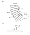
- a punching of a semi-ring plate material 101 from a plate material 100 is carried out (profile punching).
- profile punching a punching press can be applied.
- a machining for forming a slit 102 in the semi-ring plate material 101 is carried out (slit cutting).
- slit cutting a machining for forming a slit 102 in the semi-ring plate material 101 is carried out (slit cutting).
- the punching press can be also applied.
- the above slit 102 is made in two in and out in the circumferential direction of the semi-ring plate material 101 and in a large number in the radial direction of the semi-ring plate material 101, but a plate-material portion 103-1 between the large number of radial slits 102-1, 102-1 finally becomes the stator blade 31 shown in Figure 7B.
- the plate-material portion 103-2 inside the inner circumferential slit 102-2 and the plate-material portion 103-3 outside the outer circumferential slit 102-3 become, as shown in Figure 7B, the inner rim portion 32 and the outer rim portion 33 supporting the stator blade 31 (plate-material portion 103-1) Since the stator vane half 30 is constructed so that the stator blades 31 in the same shape are arranged repeatedly, only about one third of the stator vane half 30 is shown with the remaining two thirds omitted in Figure 4.
- press bending as shown in Figure 6 can be used, for example.
- the press bending in the figure is a bending in a method that opposed surfaces 200a, 201a of an upper and a lower punch 200, 201 are used as inclined press surfaces corresponding to an elevation angle ⁇ of the stator blade 31, and the plate-material portion 103-1 between the radial slits 102-1, 102-1 is pressed from both face sides by these press surfaces in the order of (a), (b) and (c) as shown in Figure 6.
- a plurality of the stator blades 31 are obtained as integrally arranged radial as shown in Figure 7B and an integral part of the plurality of stator blades 31, 31 becomes a stator vane half 30 in this embodiment.
- one end of the inner rim end 32a of the stator vane half 30 manufactured through the above processes is formed shorter in the circumferential direction with respect to the abutment line L.
- Figure 7 is a view showing processes by which the ring-shaped stator vane B is formed by abutting the two stator vane halves 30 to each other, as conventional, and Figure 8 is an enlarged view of A part and B portion in Figure 7, that is, an enlarged view of an abutted part of the stator vane half 30.
- each two of the stator vane halves 30 are arranged in the vacuum pump in the state where they are inserted from both sides, surrounding the rotor 9, between each pair of the rotor vanes 10 formed integrally in plural and many stages around the rotor 9.
- each of the stator vane halves 30 is positioned to be in the ring shape when being abutted, and it is carried out only by the abutment state of the outer rim end 33a which can be visually checked from outside.
- the gap S is formed by making cutout at the inner rim end 32a.
- This cutout may be preferably formed at a blade edge cut-and-raised side end 32a-1 of the inner rim portion 32 as shown in Figure 8 rather than the cutout terminal end 32a-2 of the inner rim portion 32.
- this gap S is preferably 0.3 to 0.7 mm or more preferably 0.5 mm.
Landscapes
- Engineering & Computer Science (AREA)
- Mechanical Engineering (AREA)
- General Engineering & Computer Science (AREA)
- Non-Positive Displacement Air Blowers (AREA)
- Structures Of Non-Positive Displacement Pumps (AREA)
Abstract
Description
- The present invention relates to a stator vane of a turbo molecular pump and particularly to reduction of breakage of the stator vane.
- Avacuumpump has, in general, a rotor rotatably installed inside a pump case and by high-speed rotation of this rotor, rotor vanes integrally cut out in a number of stages around the rotor are also rotated at a high speed. On the inner periphery of the pump case, stator vanes and the rotor vanes are alternately arranged in a number of stages.
- By interaction of the stator vanes and the rotor vanes arranged alternately in a number of stages, exhaust action of a gas molecule is carried out, and a process chamber or the like of a semiconductor device to which this vacuum pump is connected is brought into a vacuum state. That is, the rotor vane on the uppermost stage rotating at a high speed imparts a downward motion to a gas molecule having entered from a gas inlet, and the gas molecule having the downward motion is guided to the stator vane and fed into the rotor vane on the subsequent stage. By repeated operation of the above imparting of the motion to the gas molecule and feeding it in many stages, the gas molecule on the gas inlet side is sequentially transferred to the inside of a screw stator below a rotor and exhausted, by which the inside of the process chamber or the like of the semiconductor device is made vacuum.
- An interval between the stator vane and the rotor vane performing the above exhaust operation of the gas molecule is set extremely small so that the gas molecule can be exhausted efficiently.
- The stator vane is arranged radial in plural between an
inner rim portion 32 and anouter rim portion 33 as shown in Figure 7A, for example, and arranged in a vacuum pump as a stator vane B in the integrally connected state. Also, the stator vane B is generally positioned and fixed in many stages alternately with the rotor vane through a spacer on the inner circumference of the pump case by holding theouter rim portion 33. - As mentioned above, the stator vanes B are arranged alternately with the rotor vanes in many stages, and the stator vane shape is a ring and the rotor vanes are integrally cut out in many stages around the rotor. Thus, it is not possible to arrange them in the vacuum pump by placing the center hole portions of the ring-shaped stator vanes B over the rotors. Therefore, this stator vane B needs to be divided before being arranged in the vacuum pump.
- For example, this type of stator vane B is in a construction that two
stator vane halves 30, provided respectively with aninner rimportion 32, theouter rimportion 33, andaplurality ofstator blades inner rim portion 32 and theouter rim portion 33 as shown in Figure 7B, are abutted to each other by a method as shown in Figures 7A and 7B to have the ring state. And thestator vane halves 30 are inserted respectively from both sides with the rotor between them and arranged in the vacuum pump alternately with the rotor vane by being combined in the ring state in the above method. - When abutting to arrange the two
stator vane halves 30 between the rotor vanes, aninner rim end 32a and anouter rim end 33a are to be positioned in the ring shape. Since the rotor vane is integrally cut out as mentioned above and theouter rimportion 33 of thestator vane half 30 is positioned and stacked through the spacer, the abutted state of theinner rim end 32a can not be checked from the outside. - That is, when the stator vane
half 30 in the semi-ring shape is to be positioned and arranged inside the vacuum pump, the positioning is carried out only by theouter rim end 33a capable of being visually checked from the outside, while theinner rim end 32a is positioned and arranged without visual check in general. - This stator vane
half 30 in the same semi-ring shape is manufactured in plural from the viewpoint of cost reduction, work efficiency and the like using a punching press or the like (Patent Document 1). - Therefore, when the two
stator vane halves 30 are abutted to each other as in Figure 7A, theinner rim end 32 and theouter rim end 33a of each of thestator vane half 30 should be also abutted to each other and positioned on an abutment line L. However, there is a variation in manufacturedstator vane half 30 and theinner rim end 32a might be formed longer in the circumferential direction than a design dimension with respect to the abutment line L at the punching press. - If one or two of such defectively manufactured
stator vane halves 30 are abutted as above and positioned/arranged in the vacuum pump, since the abutted state of theinner rim ends 32a can not be checked, theinner rim ends 32a might collide with each other and overlap each other or be warped as shown in Figures 9A and 9B, which leads to the following problem. - That is, the interval between the
stator blade 31 and the rotor vane is set extremely small as mentioned above. Thus, if the overlap or warping as shown in Figures 9A and 9B occurs in theinner rim end 32a, the interval is further narrowed, and the overlapping or warped portion might contact the rotor vane and result in breakage of thestator blade 31 in the end. - Prevention of a cause of such breakage of the
stator blade 31 is particularly important in terms of ensuring of safety and avoidance of danger, but with such a construction as described inPatent Document 2 that the stator vane B formed by abutting the twostator vane halves 30, that is, a construction of the fixed vane B formed by abutting the twostator vane halves 30 manufactured so that the inner rim ends 32a and theouter rim ends 33a are located on the abutment line L, the breakage in thestator blade 31 caused by the overlap or warping of theinner rim end 32a can not be prevented and as a result, the breakage in thestator blade 31 can not be reduced. - Patent Document 1:
Japanese Patent Laid-Open No. 2003-269365 - Patent Document 2:
Japanese Patent Laid-OpenNo. 5-157090 - The present invention was made in order to solve the above problem and has an object to provide a stator vane of a turbo molecular pump suitable for reduction of breakage in a stator vane.
- In order to achieve the above obj ect, the present invention is a stator vane of a turbo molecular pump formed annular by abutting a pair of stator vane halves, each having a plurality of stator blades arranged radial and connected integrally by an inner rim portion and an outer rim portion, the stator vane having a gap at the abutment portion of the inner rim portion.
- This stator vane half is manufactured in plural as the same semi-ring shape through profile punching, slit cutting, and bending, for example, and the ring-shaped turbo molecular stator vane is constructed by abutting these two stator vane halves to each other.
- Also, since one end of an inner rim end of this stator vane half is formed shorter in the circumferential direction from an abutment line, the inner rim ends do not collide with each other when the two stator vane halves are abutted to each other, and a gap is formed in the inner rim portion of the ring-shaped stator vane formed by abutting these two stator vane halves.
- In the present invention, the gap may be 0.3 mm to 0.7 mm. This gap needs to be an interval to such an extent that the inner rim ends do not overlap or are warped at an abutment portion when the two stator vane halves are abutted and the gap is more preferably 0.5 mm.
- Also, this gap is formed by making one end of the inner rim end of the stator vane half shorter in the circumferential direction from the abutment line formed by abutting the two stator vane halves, and this inner rim end may be an end on the cut-and-raised side of the inner rim portion.
- If the end on the cut-out terminal end of the inner rim end is formed shorter, a portion for holding the stator blade by the inner rim portion is cut and there is a fear that holding strength of the stator blade is lowered, and thus the above method is preferable.
- In the present invention, the construction that the gap is formed in the inner rim portion in the state that the two stator vane halves are abutted together. Thus, since occurrence of the overlap or warping in the inner rim portion can be prevented when the stator vane is arranged in the vacuum pump, breakage of the stator vane can be prevented, and the stator vane which can reduce breakage of the stator vane can be obtained.
- A best mode for carrying out the present invention will be described below in detail referring to the attached drawings.
- A vacuum pump shown in Figure 1 is used as a part of a vacuum device in a semiconductor manufacturing apparatus or a liquid-crystal display panel manufacturing apparatus so as to bring a pressure in a vacuum chamber to a predetermined vacuum degree. Also, the vacuum pump in the same figure is a complex-type vacuum pump in which a turbo molecular pump and a screw groove pump are combined and constructed to have a
rotor 9 rotatably arranged in acylindrical pump case 1, in which a substantially upper half of therotor 9 functions as a turbo molecular pump, while the substantially lower half of therotor 9 functions as a screw groove pump. - This
pump case 1 is in a cylindrical case structure with a bottom having an opening on its upper face as agas inlet 2 and an exhaust pipe as agas outlet 3 is projected on one side at the lower part. Also, the bottom part of thepump case 1 is covered by anend plate 4 and at the center on the inner bottom face, astator column 5 is provided. - At the center part of this
stator column 5, arotor shaft 7 is rotatably provided, and thisrotor shaft 7 is supported by magnetic bearings made from a radial electromagnet 6-1 and an axial electromagnet 6-2 provided in thestator column 5 in the axial direction and the radial direction, respectively. - A driving
motor 8 is arranged inside thestator column 5, and this drivingmotor 8 is constructed to have a stator 8a in thestator column 5 and arotor 8b arranged at therotor shaft 7 so that therotor shaft 7 is rotated around the shaft. - Inside the
pump case 1, to an upper projecting end from thestator column 5 of therotor shaft 7, therotor 9 with a sectional shape covering the outer periphery of thestator column 5 is connected. - On the upper outer circumference of the
rotor 9,rotor vanes 10 are arranged and fixed in many stages, andstator blades 31 are arranged and fixed in many stages alternately with therotor vanes 10. - Also, a gap between the
stator blades 31 in each stage is set at a predetermined distance and positioned and fixed in the cylindrical radial direction of thepump case 1. - Gap setting and radial positioning of the
stator blade 31 in each stage are performed by a ring-shaped spacer 60 stacked in many stages on the inner circumference side of thepump case 1. - This
spacer 60 is constructed so that the upper and thelower spacers spacers 60 are stacked in stages in order to prevent lateral displacement of thespacer 60 in spacer stacking work in a pump assembling process and to enable positioning of the upper and thelower spacers pump case 1 in the same way. - Specifically, as shown in Figure 2, such a stacking/fitting structure is employed for this
spacer 60 that stepportions spacer 60, and thestep portion 61a on the upper inner circumferential face and thestep portion 61b on the lower outer circumferential face are fitted with each other. - Action of the above constructed vacuum pump will be described. First, an auxiliary pump, not shown, connected to the
gas outlet 3 is operated to bring the inside of thechamber 14 to a vacuum state to some degree, the drivingmotor 8 is operated and then, therotor shaft 7, therotor 9 connected to that and therotor vane 10 are rotated at a high speed. - And the
rotor vane 10 on the uppermost stage rotating at the high speed applies a downward motion to a gas molecule entering from thegas inlet 2, and the gas molecule having this downward motion is guided to thestator blade 31 and then, fed to therotor vane 10 side on the subsequent stage. By repeating the above application of the motion to the gas molecule and the feeding operation in many stages, the gas molecule on thegas inlet 2 side is sequentially transferred to the inside of the screw stator 12 below therotor 9 and exhausted. That is, an exhaust operation of the gas molecule is carried out by interaction between therotor vane 10 and thestator blade 31. - Moreover, the gas molecule which has reached the screw stator 12 below the
rotor 9 by the above molecular exhaust operation is compressed from a transit flow to a viscous flow and transferred to thegas outlet 3 side by the interaction between the rotatingrotor 9 and a screw groove 13 formed on the inside of the screw stator 12 and exhausted to the outside from thisgas outlet 3 through the auxiliary pump, not shown. - Next, one embodiment of the stator vane according to the present invention will be described using Figures 3 to 8.
- Since the stator vane B according to the present invention is constructed by abutting the two
stator vane halves 30 to each other, one embodiment of a manufacturing method of thisstator vane half 30 will be described first. - First, as shown by a dotted line in Figure 3 (process 1), a punching of a
semi-ring plate material 101 from aplate material 100 is carried out (profile punching). For this profile punching process, a punching press can be applied. - At this profile punching, a cutout is made at one end of an inner-rim end forming portion 101-1. By this, in the state where the two
stator vane halves 30 manufactured through the above and the followingprocesses are abutted to each other, a gap S is formed at theinner rim portion 32 as shown below. - After that, as shown by a dotted line in Figure 4 (process 2), a machining for forming a
slit 102 in thesemi-ring plate material 101 is carried out (slit cutting). For this slit cutting, the punching press can be also applied. - The
above slit 102 is made in two in and out in the circumferential direction of thesemi-ring plate material 101 and in a large number in the radial direction of thesemi-ring plate material 101, but a plate-material portion 103-1 between the large number of radial slits 102-1, 102-1 finally becomes thestator blade 31 shown in Figure 7B. - Also, in the above inner and outer two circumferential slits 102-2, 102-3, the plate-material portion 103-2 inside the inner circumferential slit 102-2 and the plate-material portion 103-3 outside the outer circumferential slit 102-3 become, as shown in Figure 7B, the
inner rim portion 32 and theouter rim portion 33 supporting the stator blade 31 (plate-material portion 103-1) Since thestator vane half 30 is constructed so that thestator blades 31 in the same shape are arranged repeatedly, only about one third of thestator vane half 30 is shown with the remaining two thirds omitted in Figure 4. - Next, bending (process 3) iscarriedout. Inthisbending, the above plate-material portion 103-1 between the radial slits 102-1, 102-1 is bent so as to be raised upward with a given elevation angle θ, that is, an optimal angle for exhaust of the gas molecule as shown in Figure 5.
- For this bending, press bending as shown in Figure 6 can be used, for example. The press bending in the figure is a bending in a method that opposed
surfaces lower punch stator blade 31, and the plate-material portion 103-1 between the radial slits 102-1, 102-1 is pressed from both face sides by these press surfaces in the order of (a), (b) and (c) as shown in Figure 6. - After the profile punching (process 1), the slit cutting (process 2) and the bending (process 3) are completed, a plurality of the
stator blades 31 are obtained as integrally arranged radial as shown in Figure 7B and an integral part of the plurality ofstator blades stator vane half 30 in this embodiment. - In this embodiment, one end of the
inner rim end 32a of thestator vane half 30 manufactured through the above processes is formed shorter in the circumferential direction with respect to the abutment line L. - By this construction, when the two stator vane halves 30 are abutted to each other, a gap S is formed at the
inner rim portion 32, which can prevent the above-mentioned overlap or warping at theinner rim portion 32 and reduce breakage of the stator vane B. - Next, one embodiment for arranging the
stator vane half 30 manufactured as above in the vacuum pump will be described using Figures 1, 7 and 8. Figure 7 is a view showing processes by which the ring-shaped stator vane B is formed by abutting the two stator vane halves 30 to each other, as conventional, and Figure 8 is an enlarged view of A part and B portion in Figure 7, that is, an enlarged view of an abutted part of thestator vane half 30. - Using two of the manufactured stator vane halves 30, each two of the stator vane halves 30 are arranged in the vacuum pump in the state where they are inserted from both sides, surrounding the
rotor 9, between each pair of therotor vanes 10 formed integrally in plural and many stages around therotor 9. - The way to abut each of the stator vane halves 30 to each other when they are inserted and arranged is similar to the conventional way as shown in Figures 7A and 7B. Moreover, it is also similar to the conventional way in the point that each of the stator vane halves 30 is positioned to be in the ring shape when being abutted, and it is carried out only by the abutment state of the
outer rim end 33a which can be visually checked from outside. - However, in the present invention, since a cutout is formed on each of the abutted stator vane halves 30 at one end of the inner-rim end forming portion 101-1 at the above-mentioned profile punching as shown in Figure 3, the one end of the
inner rim end 32a of each of the stator vane halves 30 is formed shorter in the circumferential direction with respect to the abutment line L as shown in Figure 8. - Therefore, in the present invention, as shown in Figure 7A, when the stator vane halves 30 are abutted to each other, the gap S is formed in the
inner rim portion 32 as shown in Figure 8 at the A part and the B part in Figure 7A, that is, the abutment portion of thestator vane half 30. - In this way, since the gap S is formed at the
inner rim portion 32 of the stator vane B in the present invention, even if the positioning of each of the stator vane halves 30 is carried out by visually checking only the abutted state of the outer rim ends 33a and not visually checking the abutted state of the inner rim ends 32a at all, the inner rim ends 32a of each of the stator vane halves 30 do not collide with each other, and overlap or warping between the inner rim ends 32a does not occur. - The gap S is formed by making cutout at the
inner rim end 32a. This cutout may be preferably formed at a blade edge cut-and-raisedside end 32a-1 of theinner rim portion 32 as shown in Figure 8 rather than the cutoutterminal end 32a-2 of theinner rim portion 32. - If a cutout is made at the cutout
terminal end 32a-2, a portion of theinner rim 32 for holding thestator blade 31 is cut, and there is a fear that the holding strength of thestator blade 31 is lowered. - Also, if this gap S is too large, that obstructs stability and causes rattling when the stator vane B is rotated. Thus, it may be an interval to such an extent that no overlap or warping is caused in the state where the two stator vane halves 30 are abutted to each other, and the inventor has confirmed in experiments that the gap S is preferably 0.3 to 0.7 mm or more preferably 0.5 mm.
-
- Figure 1 is a sectional view of a vacuum pump;
- Figure 2 is an enlarged view of a periphery of a spacer in the vacuum pump shown in Figure 1;
- Figure 3 is an explanatory view of a process for manufacturing a stator vane half (process 1);
- Figure 4 is an explanatory view of a process for manufacturing a stator vane half (process 2);
- Figure 5 is a view showing a state of a stator blade seen from the side after bending;
- Figure 6 is an explanatory view of a process for manufacturing a stator vane half (process view);
- Figure 7 is an assembled view of a stator vane;
- Figure 8 is an enlarged view at an abutment portion in
- Figure 7 of the stator vane according to the present invention; and
- Figure 9 is an enlarged view at an abutment portion in Figure 7 of a conventional stator vane.
-
- 1
- Pump case
- 2
- Gas inlet
- 3
- Gas outlet
- 4
- End plate
- 5
- Stator column
- 6-1
- Radial electromagnet
- 6-2
- Axial electromagnet
- 7
- Rotor shaft
- 8
- Driving motor
- 9
- Rotor
- 10
- Rotary vane
- 12
- Screw stator
- 13
- Screw groove
- 14
- Chamber
- 30
- Fixed vane aggregate
- 31
- Fixed vane
- 32
- Inner rim portion
- 32a
- Inner rim end
- 32a-1
- Cut-and-raised side end
- 32a-2
- Cutout terminal end
- 33
- Outer rim portion
- 33a
- Outer rim end
- 60
- Spacer
- 61
- Step portion
- 100
- Plate material
- 101
- Semi-ring state plate material
- 101-1
- Inner rim end forming portion
- 102
- Slit
- 200
- Punch
- B
- Stator vane
- L
- Abutment line
- S
- Gap
Claims (3)
- A stator vane of a turbo molecular pump formed annular by abutting a pair of stator vane halves, each having a plurality of stator blades arranged radial and connected integrally by an inner rim portion and an outer rim portion,
characterized in that the stator vane has a gap at the abutment portion of the inner rim portion. - A stator vane of a turbo molecular pump according to claim 1, wherein the gap is prefer ably 0 . 3 to 0.7 mm and more preferably 0.5 mm.
- A stator vane of a turbo molecular pump according to claim 1, wherein the gap is yielded by making a blade edge cut-and-raised side abutting end of the inner rim fall back from an abutment line of the two stator vane halves.
Applications Claiming Priority (2)
| Application Number | Priority Date | Filing Date | Title |
|---|---|---|---|
| JP2004264426A JP4676731B2 (en) | 2004-09-10 | 2004-09-10 | Turbo molecular pump fixed blade and vacuum pump |
| PCT/JP2005/015518 WO2006027961A1 (en) | 2004-09-10 | 2005-08-26 | Fixed vane of turbo molecular pump |
Publications (3)
| Publication Number | Publication Date |
|---|---|
| EP1795756A1 true EP1795756A1 (en) | 2007-06-13 |
| EP1795756A4 EP1795756A4 (en) | 2009-04-15 |
| EP1795756B1 EP1795756B1 (en) | 2012-01-25 |
Family
ID=36036249
Family Applications (1)
| Application Number | Title | Priority Date | Filing Date |
|---|---|---|---|
| EP05780851A Expired - Lifetime EP1795756B1 (en) | 2004-09-10 | 2005-08-26 | Fixed vane of turbo molecular pump |
Country Status (5)
| Country | Link |
|---|---|
| US (1) | US7824153B2 (en) |
| EP (1) | EP1795756B1 (en) |
| JP (1) | JP4676731B2 (en) |
| KR (1) | KR101257116B1 (en) |
| WO (1) | WO2006027961A1 (en) |
Cited By (5)
| Publication number | Priority date | Publication date | Assignee | Title |
|---|---|---|---|---|
| EP2620649A1 (en) * | 2012-01-27 | 2013-07-31 | Edwards Limited | Gas transfer vacuum pump |
| WO2013110936A3 (en) * | 2012-01-27 | 2013-10-10 | Edwards Ltd | Gas transfer vacuum pump |
| EP2913533A1 (en) * | 2014-02-28 | 2015-09-02 | Pfeiffer Vacuum Gmbh | Stator disc |
| CN107178508A (en) * | 2016-03-10 | 2017-09-19 | 埃地沃兹日本有限公司 | Vavuum pump and the quiet alar part for being used in the vavuum pump |
| WO2018029446A1 (en) * | 2016-08-08 | 2018-02-15 | Edwards Limited | Vacuum pump |
Families Citing this family (10)
| Publication number | Priority date | Publication date | Assignee | Title |
|---|---|---|---|---|
| KR20020062537A (en) * | 2001-01-22 | 2002-07-26 | 원인호 | Preparation of cold heat mint soap |
| JP2007309245A (en) | 2006-05-19 | 2007-11-29 | Boc Edwards Kk | Vacuum pump |
| KR101233849B1 (en) * | 2012-11-12 | 2013-02-15 | 김준규 | Put the fluid in the pipe spinning device manufacturing method, and how to install them |
| JP6241222B2 (en) * | 2013-01-22 | 2017-12-06 | 株式会社島津製作所 | Vacuum pump |
| JP6236806B2 (en) * | 2013-03-07 | 2017-11-29 | 株式会社島津製作所 | Vacuum pump |
| JP6241223B2 (en) | 2013-03-13 | 2017-12-06 | 株式会社島津製作所 | Vacuum pump |
| JP6660176B2 (en) * | 2015-12-25 | 2020-03-11 | エドワーズ株式会社 | Vacuum pump and split vane section used for it |
| JP7049052B2 (en) * | 2016-09-27 | 2022-04-06 | エドワーズ株式会社 | Vacuum pumps and fixed disks for vacuum pumps |
| GB2590955B (en) * | 2020-01-09 | 2022-06-15 | Edwards Ltd | Vacuum pump |
| CN114673671B (en) * | 2020-12-25 | 2024-04-02 | 广东美的白色家电技术创新中心有限公司 | Fans and vacuum cleaners |
Family Cites Families (9)
| Publication number | Priority date | Publication date | Assignee | Title |
|---|---|---|---|---|
| US2971333A (en) * | 1958-05-14 | 1961-02-14 | Gen Electric | Adjustable gas impingement turbine nozzles |
| JPS62173594U (en) * | 1986-03-22 | 1987-11-04 | ||
| IT1241177B (en) * | 1990-02-16 | 1993-12-29 | Varian Spa | STATOR FOR TURBOMOLECULAR PUMP. |
| FR2683277B1 (en) * | 1991-11-04 | 1995-01-13 | Cit Alcatel | ADJUSTABLE THICKNESS SPACER. |
| JP3013083B2 (en) * | 1998-06-23 | 2000-02-28 | セイコー精機株式会社 | Turbo molecular pump |
| DE19937393A1 (en) * | 1999-08-07 | 2001-02-08 | Leybold Vakuum Gmbh | Stator ring for a turbomolecular vacuum pump |
| DE10046766A1 (en) * | 2000-09-21 | 2002-04-11 | Leybold Vakuum Gmbh | Compound-friction vacuum pump |
| EP1249613B1 (en) * | 2001-03-15 | 2004-01-28 | VARIAN S.p.A. | Turbine pump with a stator stage integrated with a spacer ring |
| JP2003269365A (en) * | 2002-03-13 | 2003-09-25 | Boc Edwards Technologies Ltd | Vacuum pump |
-
2004
- 2004-09-10 JP JP2004264426A patent/JP4676731B2/en not_active Expired - Lifetime
-
2005
- 2005-08-26 WO PCT/JP2005/015518 patent/WO2006027961A1/en not_active Ceased
- 2005-08-26 EP EP05780851A patent/EP1795756B1/en not_active Expired - Lifetime
- 2005-08-26 US US11/662,229 patent/US7824153B2/en active Active
- 2005-08-26 KR KR1020077005376A patent/KR101257116B1/en not_active Expired - Lifetime
Cited By (9)
| Publication number | Priority date | Publication date | Assignee | Title |
|---|---|---|---|---|
| EP2620649A1 (en) * | 2012-01-27 | 2013-07-31 | Edwards Limited | Gas transfer vacuum pump |
| WO2013110936A3 (en) * | 2012-01-27 | 2013-10-10 | Edwards Ltd | Gas transfer vacuum pump |
| CN104066999A (en) * | 2012-01-27 | 2014-09-24 | 爱德华兹有限公司 | Gas transfer vacuum pump |
| US10337517B2 (en) | 2012-01-27 | 2019-07-02 | Edwards Limited | Gas transfer vacuum pump |
| EP2913533A1 (en) * | 2014-02-28 | 2015-09-02 | Pfeiffer Vacuum Gmbh | Stator disc |
| CN107178508A (en) * | 2016-03-10 | 2017-09-19 | 埃地沃兹日本有限公司 | Vavuum pump and the quiet alar part for being used in the vavuum pump |
| WO2018029446A1 (en) * | 2016-08-08 | 2018-02-15 | Edwards Limited | Vacuum pump |
| US10844864B2 (en) | 2016-08-08 | 2020-11-24 | Edwards Limited | Vacuum pump |
| EP3497337B1 (en) | 2016-08-08 | 2022-11-23 | Edwards Limited | Vacuum pump |
Also Published As
| Publication number | Publication date |
|---|---|
| JP4676731B2 (en) | 2011-04-27 |
| US20080118351A1 (en) | 2008-05-22 |
| KR101257116B1 (en) | 2013-04-22 |
| US7824153B2 (en) | 2010-11-02 |
| JP2006077713A (en) | 2006-03-23 |
| EP1795756A4 (en) | 2009-04-15 |
| KR20070050952A (en) | 2007-05-16 |
| EP1795756B1 (en) | 2012-01-25 |
| WO2006027961A1 (en) | 2006-03-16 |
Similar Documents
| Publication | Publication Date | Title |
|---|---|---|
| EP1795756B1 (en) | Fixed vane of turbo molecular pump | |
| EP2623791B1 (en) | Exhaust pump | |
| US20080317590A1 (en) | Production method of stator blade and turbo-molecular pump with the stator blade | |
| KR101277380B1 (en) | Vacuum pump | |
| KR20130114566A (en) | Exhaust pump | |
| WO2018066471A1 (en) | Vacuum pump, helical plate for vacuum pump, spacer, and rotating cylindrical body | |
| JPWO2009028099A1 (en) | Turbo molecular pump | |
| KR102519969B1 (en) | Adaptor and vaccum pump | |
| JP2003269365A (en) | Vacuum pump | |
| JP6834612B2 (en) | How to make a vacuum pump | |
| CN104033395B (en) | Vacuum pump | |
| JP4517724B2 (en) | Turbo molecular pump | |
| EP2653728B1 (en) | Fixed blade assembly usable in exhaust pump, and exhaust pump provided with same | |
| US6827550B2 (en) | Vacuum pump | |
| CN107178508B (en) | Vacuum pump and stationary blade used for the same | |
| JP2006090231A (en) | Method for manufacturing fixed blade of turbo molecular pump and vacuum pump | |
| CN107044430B (en) | Vacuum pumps and rotors and stators used therein | |
| JP2017137840A (en) | Vacuum pump and rotor and stator used therefor | |
| EP3252314A1 (en) | Vacuum pump |
Legal Events
| Date | Code | Title | Description |
|---|---|---|---|
| PUAI | Public reference made under article 153(3) epc to a published international application that has entered the european phase |
Free format text: ORIGINAL CODE: 0009012 |
|
| 17P | Request for examination filed |
Effective date: 20070305 |
|
| AK | Designated contracting states |
Kind code of ref document: A1 Designated state(s): AT BE BG CH CY CZ DE DK EE ES FI FR GB GR HU IE IS IT LI LT LU LV MC NL PL PT RO SE SI SK TR |
|
| RBV | Designated contracting states (corrected) |
Designated state(s): DE FR GB |
|
| DAX | Request for extension of the european patent (deleted) | ||
| RAP1 | Party data changed (applicant data changed or rights of an application transferred) |
Owner name: EDWARDS JAPAN LIMITED |
|
| RAP1 | Party data changed (applicant data changed or rights of an application transferred) |
Owner name: EDWARDS JAPAN LIMITED |
|
| A4 | Supplementary search report drawn up and despatched |
Effective date: 20090316 |
|
| 17Q | First examination report despatched |
Effective date: 20090826 |
|
| GRAP | Despatch of communication of intention to grant a patent |
Free format text: ORIGINAL CODE: EPIDOSNIGR1 |
|
| GRAS | Grant fee paid |
Free format text: ORIGINAL CODE: EPIDOSNIGR3 |
|
| GRAA | (expected) grant |
Free format text: ORIGINAL CODE: 0009210 |
|
| AK | Designated contracting states |
Kind code of ref document: B1 Designated state(s): DE FR GB |
|
| REG | Reference to a national code |
Ref country code: GB Ref legal event code: FG4D |
|
| REG | Reference to a national code |
Ref country code: DE Ref legal event code: R081 Ref document number: 602005032418 Country of ref document: DE Owner name: EDWARDS JAPAN LTD., YACHIYO, JP Free format text: FORMER OWNER: BOC EDWARDS JAPAN LTD., TOKIO/TOKYO, JP |
|
| REG | Reference to a national code |
Ref country code: DE Ref legal event code: R096 Ref document number: 602005032418 Country of ref document: DE Effective date: 20120322 |
|
| PLBE | No opposition filed within time limit |
Free format text: ORIGINAL CODE: 0009261 |
|
| STAA | Information on the status of an ep patent application or granted ep patent |
Free format text: STATUS: NO OPPOSITION FILED WITHIN TIME LIMIT |
|
| 26N | No opposition filed |
Effective date: 20121026 |
|
| REG | Reference to a national code |
Ref country code: DE Ref legal event code: R097 Ref document number: 602005032418 Country of ref document: DE Effective date: 20121026 |
|
| REG | Reference to a national code |
Ref country code: FR Ref legal event code: PLFP Year of fee payment: 12 |
|
| REG | Reference to a national code |
Ref country code: FR Ref legal event code: PLFP Year of fee payment: 13 |
|
| REG | Reference to a national code |
Ref country code: FR Ref legal event code: PLFP Year of fee payment: 14 |
|
| P01 | Opt-out of the competence of the unified patent court (upc) registered |
Effective date: 20230503 |
|
| PGFP | Annual fee paid to national office [announced via postgrant information from national office to epo] |
Ref country code: DE Payment date: 20240702 Year of fee payment: 20 |
|
| PGFP | Annual fee paid to national office [announced via postgrant information from national office to epo] |
Ref country code: GB Payment date: 20240701 Year of fee payment: 20 |
|
| PGFP | Annual fee paid to national office [announced via postgrant information from national office to epo] |
Ref country code: FR Payment date: 20240702 Year of fee payment: 20 |
|
| REG | Reference to a national code |
Ref country code: DE Ref legal event code: R071 Ref document number: 602005032418 Country of ref document: DE |
|
| REG | Reference to a national code |
Ref country code: GB Ref legal event code: PE20 Expiry date: 20250825 |