EP1795280A1 - Flanged housing member and apparatus and method for forming same - Google Patents
Flanged housing member and apparatus and method for forming same Download PDFInfo
- Publication number
- EP1795280A1 EP1795280A1 EP06125658A EP06125658A EP1795280A1 EP 1795280 A1 EP1795280 A1 EP 1795280A1 EP 06125658 A EP06125658 A EP 06125658A EP 06125658 A EP06125658 A EP 06125658A EP 1795280 A1 EP1795280 A1 EP 1795280A1
- Authority
- EP
- European Patent Office
- Prior art keywords
- forming
- die
- flange
- flanged
- trunk portion
- Prior art date
- Legal status (The legal status is an assumption and is not a legal conclusion. Google has not performed a legal analysis and makes no representation as to the accuracy of the status listed.)
- Granted
Links
Images


Classifications
-
- B—PERFORMING OPERATIONS; TRANSPORTING
- B21—MECHANICAL METAL-WORKING WITHOUT ESSENTIALLY REMOVING MATERIAL; PUNCHING METAL
- B21K—MAKING FORGED OR PRESSED METAL PRODUCTS, e.g. HORSE-SHOES, RIVETS, BOLTS OR WHEELS
- B21K1/00—Making machine elements
- B21K1/76—Making machine elements elements not mentioned in one of the preceding groups
- B21K1/762—Coupling members for conveying mechanical motion, e.g. universal joints
-
- B—PERFORMING OPERATIONS; TRANSPORTING
- B21—MECHANICAL METAL-WORKING WITHOUT ESSENTIALLY REMOVING MATERIAL; PUNCHING METAL
- B21K—MAKING FORGED OR PRESSED METAL PRODUCTS, e.g. HORSE-SHOES, RIVETS, BOLTS OR WHEELS
- B21K23/00—Making other articles
- B21K23/04—Making other articles flanged articles
Definitions
- the present invention generally relates to a flanged housing member and particularly, but not exclusively, to a flanged housing member in which a flange is disposed at one end of a trunk portion. More specifically, the present invention relates to an ironing process, which is a kind of cold working, used to form a flange portion on a tubular trunk portion in which the flange portion and the trunk portion are formed as a one-piece, unitary member. Aspects of the invention relate to a member, to an apparatus, to a device, to a method and to a vehicle.
- a vehicle power train includes a rotation torque transmitting device that often has a constant-velocity joint.
- the constant-velocity joint sometimes has an outer ring that is a flanged housing member having a trunk portion with a blind bore and a flange protruding outward from the closed end of the trunk portion.
- the blind bore of the trunk portion can be provided with a plurality of tracks or grooves formed in its internal surface such that a gauge guide surface is formed between the tracks or grooves.
- One conventional method for forming such a flanged housing member involves first forming the internal and external surfaces of the trunk portion and then thereafter welding a flange to one end of the trunk portion to close the end of the trunk portion.
- this is disadvantageous from the aspect of cost in that two components, i.e., a flange and a trunk portion, are required to be welded together.
- another conventional method involves a hot-forging process in which a flanged forged material is first formed with a through-hole. Thereafter, the external surface of the flanged forged material is machined to achieve a prescribed outside diameter and to obtain a prescribed flange and other components.
- the tracks or grooves and the gauge guide surfaces in the internal surface are formed by broaching and performing induction hardening. Then, in this method, a cover is attached to one end of the trunk portion.
- machining and broaching require processing time, with broaching itself being costly. Thus, this manufacturing process is inferior in terms of manufacturing costs.
- a method is disclosed in which the flanged cylindrical member is formed using a cold forming process.
- This cold forming process includes using a punch to finishing the internal surface of the trunk portion.
- the punch is inserted into the trunk portion from the opposite side of the flange, and a die is then thereafter inserted from the same direction as the punch to shape the external surface of the trunk portion.
- a conventional method of manufacturing a flanged cylindrical member that has a blind bore is disclosed in Japanese Laid-Open Patent Application No. 63-273523 .
- a method is disclosed in which the flanged cylindrical member is formed using a cold forming process.
- a forged workpiece is supported with its flange side facing downward.
- a punch for finishing the interior surface is inserted inside the trunk portion, and an ironing die divided into a plurality of parts along the axial center is disposed on the external surface to shape the external surface of the workpiece by moving the punch or the ironing die in the axial direction and passing the workpiece through the interior of the die.
- the internal surface of the workpiece is brought into close contact with the external surface of the punch, and the internal and external surfaces of the workpiece are finished.
- Embodiments of the invention may provide a flanged housing member, and a forming method and apparatus therefor, in which an entire external surface of the flanged housing member can be formed such that the number of components can be reduced, the lead time can be shortened, and the manufacturing process can be improved at least from the aspect of cost.
- a flanged component forming method for forming a flanged housing member comprising holding a forming material having a pre-flanged forming portion that is disposed at one end of a trunk portion, sizing at least an internal surface of the trunk portion using a first die having an external forming surface and a second die having an internal forming surface and sandwiching and pressing the pre-flanged forming portion between the first die and a flange-forming die to form a flange portion on the end of the trunk portion.
- the sandwiching and pressing of the pre-flanged forming portion are performed after the sizing of the internal surface of the trunk portion.
- the sandwiching and pressing of the pre-flanged forming portion are performed during relative movement between the second die and the forming material immediately after the sizing of the internal surface of the trunk portion.
- the sandwiching and pressing of the pre-flanged forming portion are performed during the sizing of the internal surface of the trunk portion.
- the sizing of the internal surface of the trunk portion includes initially sizing an initial portion of the internal surface of the trunk portion to a prescribed length, and then subsequently resizing a remainder portion of the internal surface of the trunk portion after performing the sandwiching and pressing of the pre-flanged forming portion to form the flange on the end of the trunk portion.
- the sandwiching and pressing of the pre-flanged forming portion with the flange-forming die is performed when a back surface of the second die that faces the flange-forming die is aligned with a distal end of the first die.
- the sandwiching and pressing of the pre-flanged forming portion is performed in a stopped state in which the second die is supported by a fixing device.
- the holding of the forming material includes providing the pre-flanged forming portion of the forming material with a size that is equal to or less than an outside diameter of the trunk portion.
- the holding of the forming material includes providing the pre-flanged forming portion of the forming material with excess material in positions that correspond to a shape of the flange after formation.
- a flanged component forming device for forming a flanged housing member comprising a first die including an external forming surface that is configured and arranged to form an internal surface of a trunk portion of a forming material having a pre-flanged forming portion that is disposed at one end of the trunk portion, a second die including an internal forming surface that is configured and arranged to cooperate with the first die to iron the trunk portion of the forming material against the external forming surface of the first die upon relative movement of the first and second dies and a flange-forming die configured and arranged to sandwich and press the pre-flanged forming portion of the forming material against the first die to form a flange portion on one end of the trunk portion.
- the flange-forming die is further configured and arranged to set, as a sandwiching and pressing position to sandwich and press the pre-flanged forming portion, a passage position at which one of the first and second dies has completed sizing the trunk portion of the forming material across an entire axial length.
- the flange-forming die is further configured and arranged to set, as a sandwiching and pressing position to sandwich and press the pre-flanged forming portion, a position at which one of the first and second dies has only partially sized the trunk portion of the forming material in an axial direction of the trunk portion.
- the second die is held by a fixing device in a fixed position when the flange portion is being formed by sandwiching and pressing the forming material with the flange-forming die.
- the flange-forming die includes a flange forming recess formed on a surface against which the forming material is pressed into by the first die to form the flange portion.
- the second die includes a flange forming recess formed on a surface against which the forming material is pressed into by the first die and the flange-forming die to form the flange portion.
- the first and second dies are further configured and arranged to accommodate the forming material in which the pre-flanged forming portion has a size that is equal to or less than the outside diameter of the trunk portion.
- the first and second dies are further configured and arranged to accommodate the forming material in which the pre-flanged forming portion is provided with excess material so as to correspond to a shape of the flange after formation.
- a flanged component forming device for forming a flanged housing member comprising first forming means for forming an internal surface of a trunk portion of a forming material having a pre-flanged forming portion that is disposed at one end of the trunk portion second forming means for cooperating with the first forming means to iron the trunk portion of the forming material against the first forming means upon relative movement of the first and second forming means and flange-forming means for sandwiching and pressing the pre-flanged forming portion of the forming material against the first forming means to form a flange portion on one end of the trunk portion.
- a flanged housing member comprising a trunk portion including a bore with an internal surface, a closure portion closing one end of the bore of the trunk portion and a flange portion protrudes outward from the trunk portion at the one end of the bore of the trunk portion, the trunk portion, the closure portion and the flange portion being integrally formed together as a one-piece, unitary component, with the trunk portion, the closure portion and the flange portion having a continuous grain flow from the flange portion to the trunk portion due to ironing and sizing the trunk portion.
- the continuous grain flow is at least partially defined by a continuous line that extends from one side surface of the flange portion into an interior of the flange portion toward a protruding direction of the flange portion, curves and returns inside the flange portion, and then arrives at the trunk portion.
- the continuous grain flow extends from inside the flange portion and ends at the internal surface of the trunk portion.
- a flanged component forming method is provided to form a flanged housing member.
- the flanged component forming method comprises holding a forming material having a pre-flanged forming portion that is disposed at one end of a trunk portion; sizing at least an internal surface of the trunk portion using a first die having an external forming surface and a second die having an internal forming surface; and sandwiching and pressing the pre-flanged forming portion between the first die and a flange-forming die to form a flange portion on the end of the trunk portion.
- the term “sizing” refers to applying pressure to a workpiece by using a die in order to improve dimensional precision.
- flange commonly refers to a portion that protrudes outwardly in a radial direction from an external surface of a trunk portion.
- closure refers solely to a portion that closes an end portion of a trunk portion. Unless otherwise described in the present specification, the term “flange” will refer to the portion that is integrally formed with the closure for closing the end portion of the trunk portion.
- the flanged component forming method of the first embodiment of the present invention includes providing a forming material W that is reshaped to a flanged housing member (formed article) Wa as explained below.
- the forming material W comprises a relatively hard metal material that is deformable using cold forming and/or warming forming processes as described herein to form the flanged housing member (formed article) Wa as explained below.
- the forming material W basically includes a cylindrical (i.e., tubular) trunk portion 1 with a blind internal bore and a pre-flanged forming portion 2 that is deformed to form a flange portion F.
- the trunk portion 1 and the flange portion F are formed as a one-piece, unitary member in the flanged housing member (formed article) Wa.
- the formed article Wa can be used for an outer ring of a constant-velocity joint that is used into a rotating torque transmitting mechanism of a vehicle engine. Therefore, the pre-flanged forming portion 2 is disposed so as to close the opening at one end of the trunk portion 1.
- trunk portions 1 of this embodiment and the following embodiments are used for the outer ring of a constant-velocity joint, and thus, the cross section of the trunk portion 1 is circular.
- the present invention can also be applied to other components, and the cross-section of the trunk portion 1 is therefore not necessarily required to be circular.
- a rectangular cross section or another irregular shape can be used.
- the flanged component forming device basically includes a punch 10 mounted on a base 11, a sizing die 15 mounted on a press ram 16 by a support member 17 so that the sizing die 15 can be lifted and lowered relative to the punch 10, and a flange-forming die 19 for sandwiching and pressing the pre-flanged forming portion 2.
- the punch 10 basically constitutes a "first die” that is configured and arranged to form an internal surface of the trunk portion 1 of the forming material W.
- the sizing die 15 basically constitutes a "second die” that is configured and arranged to form an external surface of the trunk portion 1 of the forming material W and squeeze the trunk portion 1 of the forming material W against the punch 10 ("first die") to form an internal surface of the trunk portion 1 of the forming material W.
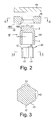
- Figure 3 is a simplified schematic cross-sectional view of the punch as viewed along section line 3-3 of Figure 2.
- Figure 4 is a simplified schematic cross-sectional view of the sizing die as viewed along section line 4-4 of Figure 2.
- the method for forming a flanged housing member is described first.
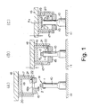
- the forming material W is held on the punch 10 ("first die"), as shown in diagram (A) of Figure 1.
- the forming material W is ironed in cooperation with the sizing die 15 ("second die"), as shown in diagram (B) of Figure 1.
- the internal and external surfaces of the trunk portion 1 are sized using the punch 10 and the sizing die 15.
- the pre-flanged forming portion 2 is deformed to form a flange portion F, as shown in diagram (C) of Figure 1.
- the flanged component forming device used in this case uses the punch 10 to hold the forming material W.
- the punch 10 has an external surface (also referred to as "external forming surface” for simplification of description) that constitutes a forming surface of the forming material W.
- the sizing die 15 is used to iron the forming material W held by the punch 10 for sizing the internal and external surfaces of the trunk portion 1 of the forming material W.
- the sizing die 15 has an internal surface (also referred to as "internal forming surface” for simplification of description) that constitutes a forming surface of the external surface of the trunk portion 1 of the forming material W.
- the flange-forming die 19 is configured and arranged for sandwiching and pressing the pre-flanged forming portion 2 against the punch 10, as shown in Figure 2, to form the flange portion F (see diagram (C) of Figure 1).
- the punch 10 is a pillar-shaped body disposed upright in a fixed position on the base 11, as shown in diagram (A) of Figure 1.
- the upper portion of the punch 10 is provided with an external forming surface having a plurality of protruding splines 12 and a plurality of concave grooves 13 disposed an alternately manner.
- the protruding splines 12 are used to form a plurality of tracks or grooves on the internal surface of the trunk portion 1.
- the concave grooves 13 are used to form a gauge guide surface between the tracks or grooves on the internal surface of the trunk portion 1, as shown in Figure 2 and 3.
- the sizing die 15 is mounted by way of the support member 17 on the press ram 16 so as to be lifted and lowered relative to the punch 10.
- the sizing die 15 is a ring-shaped member having a center-positioned opening 18 for ironing the trunk portion 1 of the forming material W whereby the forming material W is pressed against the external surface of the punch 10, as shown in Figure 2 and 4.
- the internal forming surface is not limited to an arcuate surface, and can be a surface having various shapes.
- the substantially lower half of the opening 18 in the present embodiment includes a tapered portion 18a, while the substantially upper half of the opening 18 in the present embodiment includes a cylindrical portion 18b.
- the tapered portion 18a is used in order to facilitate the ironing of the forming material W.
- the cylindrical portion 18b is used in order to size the forming material W to a prescribed outside diameter.
- the cylindrical portion 18b of the opening 18 of the sizing die 15 can essentially eliminated if needed and/or desired.
- tapered portion 18a can extend to an arcuate portion 18c such that the intersecting point has an internal size (diameter or width) and shape that corresponds to the size and shape of the formed article Wa.
- the arcuate portion 18c has a prescribed radius R, with the tapered portion 18a is rectilinearly sloped away from the arcuate portion 18c.
- the flange-forming die 19 is disposed on the press ram 16, and the lower surface thereof is a plate-shaped member which forms a flat pressing surface 20.
- the flange-forming die 19 is disposed on the press ram 16, and the lower surface thereof is a plate-shaped member which forms a flat pressing surface 20.
- the removal member 21 can be spring loaded and urged toward the center by a spring 22 disposed at the back end.
- the distal end of the removal member 21 comprises a tapered surface so as to facilitate the passage of the forming material W.
- the pre-flanged forming portion 2 is configured so that the outside diameter D1 of the pre-flanged forming portion 2 is equal to or less than the outside diameter D2 of the trunk portion 1, as shown in Figure 2.
- the outside diameter D1 of the pre-flanged forming portion 2 is advantageously less than the minimum inside diameter of the opening 18 with the outside diameter D2 of the trunk portion 1 being larger than the minimum inside diameter of the opening 18.
- the entry of the pre-flanged forming portion 2 into the opening 18 is thereby facilitated, sizing is more easily performed by ironing against the external periphery of the trunk portion 1 which has an outside diameter that is slightly greater than the inside diameter of the opening 18.
- reduced precision can be prevented in the formation of the formed article Wa when produced in accordance with the present invention.
- the flange-forming die 19 that forms the pre-flanged forming portion 2 performs the process of sandwiching and pressing the pre-flanged forming portion 2 immediately after the sizing die 15 has sized the entire length of the trunk portion 1, or while the sizing die 15 is moving with respect to the forming material W.
- the process of sandwiching and pressing by the flange-forming die 19 can also be performed midway during the sizing process performed by the sizing die 15.
- the flange-forming die 19 can be disposed directly below the press ram 16, as shown in Figure 1, so that the space between the flange-forming die 19 and the sizing die 15 provides a distance sufficient to allow the punch 10 that accompanies the forming material W to enter into the space.
- the flange-forming die 19 can also be disposed in a position underneath and at a distance from the press ram 16, and the formation of the pre-flanged forming portion 2 can begin immediately when the punch 10 that accompanies the forming material W enters the above-described space.
- the sandwiching and pressing position at which the flange-forming die 19 sandwiches and presses the forming material W can be a passage position in which the punch 10 has completed sizing across the entire axial length of the trunk portion 1 of the forming material W, or can be a midway position in the axial direction of the of the trunk portion 1.
- the term "passage position" refers a position that immediately follows sizing, or can be a position that occurs during the relative movement of the punch 10 and the sizing die 15.
- the forming material W is set on the upper portion of the punch 10, and the press ram 16 is lowered as shown in diagram (A) of Figure 1.
- the forming material W is ironed by the tapered portion 18a and the cylindrical portion 18b of the sizing die 15, as shown in diagram (B) of Figure 1, and is sized to a prescribed outside diameter.
- the shapes of the protruding splines 12 and the concave grooves 13 of the punch 10 are transferred, and the tracks or grooves and the gauge guide surface are formed on the trunk portion 1 of the forming material W.
- This ironing process is performed across the entire axial length of the trunk portion 1 of the forming material W, and thus the trunk portion 1 is formed with a high degree of precision across the entire body of the trunk portion 1 of the forming material W.
- the forming material W can thus be sized, the tracks or grooves and the gauge guide surface can be formed, and the flange portion F can all be produced in a single pressing process. Therefore, the formed article Wa can be obtained in a very simple manner. If the forming material W is temporarily detached from the punch 10 when the flange portion F is formed in another step, then the shape of the internal surface of the trunk portion 1 tends to deform after forming, and precision tends to be compromised. However, in the present embodiment, since the flange is formed without detaching the forming material W from the punch 10, a very high degree of precision is achieved across the entire length of trunk portion 1.
- the trunk portion 1 and the flange portion F can be integrated into the formed article Wa by carrying out the formation in a single press process that includes the flange portion as well, the flange portion does not need to be welded on afterward. Also since the heat of welding is not applied, the formed article Wa with excellent strength can be formed that is thinner and more lightweight then with other types of processes that use welding. Also, not only can costs be thereby reduced, but because heat deformation does not occur, precision is improved, acoustic vibration characteristics are improved, the occurrence of joint knockings is prevented, and joint characteristics are improved in comparison to other types of processes that use welding. The number of components and steps can also be reduced.
- the so-called draft angle when a formed article is obtained by hot forging in a conventional manner, the so-called draft angle must be increased and internal burrs generated within the trunk portion 1 must be removed. Therefore, the precision of the formed article is reduced and the inner surface of the trunk portion tends to be damaged.
- the draft angle does not need to be increased, the inside of the trunk portion 1 can be easily sized, high sizing precision is obtained, and a decarburized layer is not formed.
- the distal end of the removal member 21 can engage the formed article Wa and be removed from the upper portion of the punch 10.
- the formed article Wa is removed from the die by an ejection mechanism (not shown).
- the flange portion F is integrally formed with the closure Fa, as shown in diagram (C) of Figure 1, but in some cases, the flange does not have a closure Fa, i.e., the flange can be formed having only the portion protruding in the radial direction from the external surface of the trunk portion.
- a forming material W must be used in which the pre-flanged forming portion 2 is cylindrically shaped.
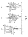
- FIG. 6 a flanged component forming method in accordance with a second embodiment will now be explained.
- the parts of the second embodiment that are identical to the parts of the first embodiment will be given the same reference numerals as the parts of the first embodiment.
- the descriptions of the parts and steps of the second embodiment that are identical to the parts and steps of the first embodiment may be omitted for the sake of brevity.
- Diagrams (A) to (C) of Figure 6 schematically illustrate the flanged component forming method according to the second embodiment of the present invention in cross-section.
- the flange-forming die 19 is operated by an independent lifting mechanism (not shown), which is different than the first embodiment.
- the forming material W is first set on the upper portion of the punch 10, as shown in diagram (A) of Figure 6, and the flange-forming die 19 is lowered to the vicinity of the sizing die 15 using the lifting mechanism.
- the forming material W is ironed by the sizing die 15 in the same manner as in the first embodiment described above.
- the forming material W is sized to a prescribed outside diameter, and tracks or grooves and the gauge guide surface are formed on the trunk portion 1.
- the ironing is also performed over the entire axial length of the trunk portion 1 of the forming material W. Therefore, the formed trunk portion 1 is provided with a high degree of precision over the entire length.
- the flange-forming die 19 is lowered to the vicinity of the sizing die 15, and pressure is applied by the lifting mechanism.
- the forming material W ironed by the sizing die 15 that is held on the punch 10. Therefore, the pre-flanged forming portion 2 deformed by the pressing surface 20, which is the lower surface of the flange-forming die 19, such that the pre-flanged forming portion 2 is pressed, and the flange portion F is formed to a prescribed thickness.
- the position in which the pre-flanged forming portion 2 is sandwiched and pressed in the present embodiment is different from that of the first embodiment.
- the pre-flanged forming portion 2 is sandwiched and pressed by the flange-forming die 19 when a distal end of the punch 10 and a back surface of the sizing die 15 are aligned at substantially the same time as sizing.
- the term "align” refers to a situation in which the distal end (upper free end surface) of the punch 10 and the back surface (upper surface facing the flange-forming die 19) of the sizing die 15 are in a matching arrangement in the movement directions of these two components.
- the flange-forming die 19 is raised by the lifting mechanism at the same time the press ram 16 is raised or after formation is completed.
- the forming material W is removed by engaging the formed article Wa with the aid of the removal member 21 disposed in a position that does not interfere with the flange-forming die 19, and detaching the article from the punch 10.
- the article is removed from the die by an ejection mechanism (not shown).
- the forming material W can be sized, tracks or grooves and the gauge guide surface can be formed, and various other effects can be achieved in a single press operation in the same manner as in the first embodiment described above.
- the flanged component forming method according to the third embodiment is designed to finish the flange portion F in the flange-forming die 19 into a prescribed shape.
- the flange-forming die 19 of this third embodiment of the present invention has a forming recess or surface 23.
- the forming recess 23 for forming a flange is formed, for example, on the pressure application surface of the flange-forming die 19, as shown in diagram (A) of Figure 7, the pre-flanged forming portion 2 of the forming material W can be sandwiched and pressed against the punch 10.
- the pre-flanged forming portion 2 can be formed into a prescribed shape that corresponds to the forming recess 23. Therefore, if a concavity 24 for forming a guide portion 25 that connects the constant-velocity joint and other components of the rotation torque transmission mechanism is provided, for example, to the forming recess 23, the formed article Wa after formation will have the guide portion 25, and the ease of assembly and processability will be improved.
- the forming recess 23 is disposed in such a flange-forming die 19, and the forming recess 23 is used to form the pre-flanged forming portion 2.
- Figure 8 is a simplified schematic diagram, in cross-section, showing the main parts of the flanged component forming device in accordance with a first modification of the third embodiment of the present invention.
- Figure 9 is a pair of simplified schematic views of a workpiece material produced by warm forging, with view (A) of Figure 9 being a cross-sectional view of the workpiece material as viewed along section line 9A-9A of view (B) of Figure 9, and with view (B) of Figure 9 being a cross-sectional view of the workpiece material as viewed along section line 9B-9B of view (A) of Figure 9.
- Figure 10 is a pair of simplified schematic views of a formed article in a state following flange portion formation, with view (A) of Figure 10 being a cross-sectional view of the formed article as viewed along section line 10A-10A of view (B) of Figure 10, and with view (B) of Figure 10 being a cross-sectional view of the formed article as viewed along section line 10B-10B of view (A) of Figure 10.
- the formed article Wa of the present modification has the flange portion F uniformly extending in the outward radial direction from the trunk portion 1, as shown in the views (A) and (B) of Figure 10.
- the forming material W is a material in which the pre-flanged forming portion 2 has a uniform prescribed thickness t 1 as shown in the view (A) of Figure 9.
- the pre-flanged forming portion 2 is disposed on the upper portion of the trunk portion 1, as shown in the views (A) and (B) of Figure 9.
- the flange portion F is formed with a flat and circular, disc-like shape (discoid) as seen in Figure 10.
- Figure 11 is a simplified schematic diagram, in cross-section, showing the main parts of the flanged component forming device in accordance with a second modification of the third embodiment of the present invention.
- Figure 12 is a pair of simplified schematic views of a workpiece material produced by warm forging, with view (A) of Figure 12 being a cross-sectional view of the workpiece material as viewed along section line 12-12 of view (B) of Figure 12, and with view (B) of Figure 12 being a top plan view of the workpiece material illustrated in view (A) of Figure 12.
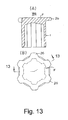
- Figure 13 is a pair of simplified schematic views of a formed article in a state following flange portion formation, with view (A) of Figure 13 being a cross-sectional view of the formed article as viewed along section line 13-13 of view (B) of Figure 13, and with view (B) of Figure 13 being a top plan view of the formed article illustrated in view (A) of Figure 13.
- the formed article Wa of the present modification has the flange portion F with a plurality of radial protrusions 26, as shown in Figure 13.
- the protrusions 26 protrude from the trunk portion 1 in the radial direction.
- the forming material W is a material in which the pre-flanged forming portion 2 has a uniform prescribed thickness t 2 , as shown in the views (A) and (B) of Figure 13.
- the pre-flanged forming portion 2 is disposed on the upper portion of the trunk portion 1, as shown in the views (A) and (B) of Figure 13.
- the flange-forming die 19 is uses the forming recess 23 in which a plurality of concavities corresponding to the protrusions 26 are formed in the internal surface of the die.
- the flange portion F is formed having the protrusions 26 corresponding to the shape of the forming recess 23.
- Figure 14 is a pair of simplified schematic views of a workpiece material produced by warm forging, with view (A) of Figure 14 being a cross-sectional view of the workpiece material as viewed along section line 14-14 of view (B) of Figure 14, and with view (B) of Figure 14 being a top plan view of the workpiece material illustrated in view (A) of Figure 14.
- Figure 15 is a pair of simplified schematic views of a formed article in a state following flange portion formation, with view (A) of Figure 15 being a cross-sectional view of the formed article as viewed along section line 15-15 of view (B) of Figure 15, and with view (B) of Figure 15 being a top plan view of the formed article illustrated in view (A) of Figure 15.
- the formed article Wa of the present modification is one in which the flange-forming die 19 is used that is substantially the same as the flange-forming die used in the second modification described above.
- the flange portion F is formed a shape in which three protrusions 27 protrude from the trunk portion 1.
- the forming material W is a material in which the pre-flanged forming portion 2 has excess material, as shown in diagrams (A) and (B) of Figure 14 that is in a portion that is used to form the flange portion F on the upper portion of the trunk portion 1 as shown in diagrams (A) and (B) of Figure 15.
- a relatively large flange portion F is formed from the excess material, and the machining allowance can therefore be reduced when the formed article is to be machined.
- the portion having excess material disposed in the pre-flanged forming portion 2 is not necessarily required to be disposed in uniform positions in the peripheral direction, and an irregularly shaped flange portion F can be formed by disposing the excess material in a nonuniform manner.
- an irregularly shaped flange portion F is formed by disposing excess material in the pre-flanged forming portion 2, but an irregularly shaped flange portion F can also be formed by ironing the pre-flanged forming portion 2, forming the flange portion F using the flange-forming die 19, and trimming the external periphery of the flange portion F. Machining, plastic working, and other methods can be used as the trimming method.
- Such a configuration allows an irregularly shaped flange portion F to be rapidly formed in a simple manner.
- the forming material W is held by the punch 10, and the forming material W held on the punch 10 is ironed by the sizing die 15, but a reverse arrangement is also possible.
- the forming material W can be held by the die 15 and the forming material can be ironed by the cooperative work of the die 15 and punch 10.
- the first and second dies of the embodiment described above can be used in reverse to carry out the forming procedure.
- the flanged component forming device of this present embodiment has the sizing die 15 holding the forming material W, as shown in diagram (A) of Figure 16.
- the punch 10 irons the forming material W by cooperatively working with the sizing die 15 to size the internal and external surfaces of the trunk portion 1, as shown in diagram (B) of Figure 16..
- the flange-forming die 19 forms the flange portion F by sandwiching and pressing the pre-flanged forming portion 2 between the punch 10 the surface 20 of the flange-forming die 19, as shown in diagram (C) of Figure 16.
- the punch 10 is a columnar body that is mounted on the press ram 16, while the sizing die 15 is disposed in a fixed position.
- the forming material W is held in the central opening 18 of the sizing die 15.
- the opening 18 has a configuration in which the substantially lower half has the tapered portion 18a, and the substantially upper half has the cylindrical portion 18b.
- the forming material W is held by the tapered portion 18a, which is the upper half of the opening 18.
- the forming material W is set in the lower portion of the sizing die 15, as shown in diagram (A) of Figure 16.
- the forming material W is ironed by the tapered portion 18a and the cylindrical portion 18b of the sizing die 15 and the punch 10, as shown in diagram (B) of Figure 16.
- the trunk portion 1 of the forming material W is sized to a prescribed outside diameter.
- the sizing of the forming material W, the forming of tracks or grooves and the gauge guide surface, and the forming of a flange can be performed in a single press operation in the same manner as in the prior embodiment described above.
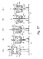
- Diagram (A) of Figure 17 shows a set state of the forming material
- diagram (B) of Figure 17 shows a temporarily stopped state in the early stage of the sizing step.
- Diagram (C) of Figure 17 shows a flange-forming state in a temporarily stopped state.
- Diagram (D) of Figure 17 shows a state in which sizing has been completed.
- Diagram (E) of Figure 17 shows a state in which the formed article can be ejected.
- the pre-flanged forming portion 2 of the forming material W is sandwiched and pressed while supported only by the punch 10. For this reason, the corners that reach from the internal surface of the pre-flanged forming portion 2 to the internal surface of the trunk portion 1 bulge outward. Thus, cavities due to so-called shrink marks are produced, the entire forming material W moves in the forming direction from a midway point in the process in which the flange portion F is being formed, and the forming precision is reduced. Furthermore, the forming material W cannot be finished into a flat, well-formed flange portion F having a surface orthogonal to the axis, and the pre-flanged forming portion 2 having considerable volume may be required in order to obtain the desired outside diameter.
- the sizing die 15 is temporarily stopped in a state in which the upper portion of the trunk portion 1 of the forming material W has been sized, the upper portion of the trunk portion 1 of the forming material W is held by the sizing die 15 from the external periphery, the movement of the forming material W is restricted, and the pre-flanged forming portion 2 is sandwiched and pressed by the flange-forming die 19 in this state and compressed to form a flange portion F.
- the forming material W is set on the upper portion of the punch 10, the press ram 16 is lowered, a first sizing is performed to a prescribed length in the axial direction, and the process is then stopped, as shown in diagram (A) of Figure 17.
- the forming material W is ironed by the tapered portion 18a and the cylindrical portion 18b of the sizing die 15, as shown in diagram (B) of Figure 17, and a prescribed length in the axial direction is sized to a prescribed outside diameter.
- the stop position of the sizing die 15 is a position at which the distal end of the punch 10 and the back surface of the sizing die 15 are aligned. In this position, the flange portion F can be received by the punch 10, and also by the sizing die 15 during flange portion formation, and the flange portion F can be formed using the flat back surface 15a of the sizing die 15. Therefore, the occurrence of cavities produced by shrinkage can be prevented, the flange portion F can be made flatter, and the precision of the formed article Wa can be further improved.
- the press ram 16 is then lowered further, as shown in diagram (D) of Figure 17, and the remaining portion of the forming material W is subjected to a second sizing.
- the second sizing transfers the shape of the concave grooves 13 and the protruding splines 12 of the punch 10 to the internal surface of the trunk portion 1.
- the formed article Wa is obtained in which the tracks or grooves and the gauge guide surface are formed. Ironing is thereby performed in the axial direction across the entire length of the trunk portion 1 of the forming material W, and very high degree of precision can be achieved across the entire trunk portion 1.
- the present embodiment allows the shape of the internal surface of the formed trunk portion 1 to remain unchanged, the required precision to be preserved, and very high degree of precision to be achieved across the entire trunk portion 1. This is because the process is stopped after the first sizing, and the second sizing is performed to thereby size the forming material W, form the tracks or grooves and the gauge guide surface, and form the flange portion in a single press operation.
- the formed article Wa can be removed from the die by using an ejection mechanism (not shown) or the like.
- the flange-forming die 19 can be raised immediately after the formation of the flange portion F or simultaneous to the second sizing.
- the forming material W is held only by the sizing die 15 from the external periphery during flange portion formation. Therefore, when pressing force is applied by the flange-forming die 19 to the forming material W, the sizing die 15 may occasionally cause positional displacement. Since this positional displacement tends to negatively affect the formation of the flange portion F, the position of the sizing die 15 is fixed in the present embodiment by using a fixing device K.
- the fixing device K can be any type of fixing device as long as the sizing die 15 can be supported in a fixed position.
- the fixing device K includes a die cushion 30.
- the die cushion 30 comprises a cushion pad 31 that is coaxially disposed about the periphery of the punch 10, and a plurality of cushion pins 32 for supporting the cushion pad 31 while the cushion pad 31 can move up and down.
- the cushion pad 31 moves upward to support the sizing die 15 from below, as shown in diagram (C) of Figure 18.
- the sizing die 15 holds the initial stop position horizontally even if the forming material W is pressed by the flange-forming die 19.
- the fixing device K can further include a hydraulic mechanism, a spring, a gas cushion, or other device used in closed die sets. Also, a stopper member (not shown) can be disposed laterally of the punch 10, assume a protruding position when the sizing die 15 is stopped, and support the sizing die 15 from below.
- the forming material W is set on the upper portion of the punch 10, as shown in diagram (A) of Figure 18, in the same manner as in the sixth embodiment described above.
- the press ram 16 is lowered, as shown in diagram (B) of Figure 18.
- a portion of the trunk portion 1 of the forming material W is ironed by the sizing die 15. The first sizing is performed and the process is then stopped. The external surface of a portion of the trunk portion 1 of the forming material W is thereby sized to a prescribed outside diameter.
- the cushion pad 31 is raised by the cushion pins 32 toward the stopped sizing die 15 to support the sizing die 15 from below, as shown in diagram (C) of Figure 18.
- the flange-forming die 19 is lowered, the forming material W is pressed, and the flange portion F is formed.
- the sizing die 15 is constantly held by the die cushion 30 during the processing performed by the flange-forming die 19, and the sizing die 15, which supports the periphery of the trunk portion of the forming material W, does not become displaced. Forming can therefore be smoothly performed and the precision of the formed article Wa can be improved.
- the pressing surface 20 which is the lower surface of the flange-forming die 19
- the material is pressed and deformed using the back surface 15a (see diagram (C) of Figure 18) of the sizing die 15, and a flat flange portion F can be formed to a prescribed thickness.
- the press ram 16 is lowered again and the trunk portion of the forming material W is subjected to a second sizing by ironing using the sizing die 15, as shown in diagram (D) of Figure 18.
- the entire trunk portion of the forming material W is thereby sized and finished to a prescribed outside diameter, and the tracks or grooves and the gauge guide surface are formed on the internal surface.
- the forming material W can be sized, and tracks or grooves and a gauge guide surface can be formed in a single press operation in the same manner as in the first embodiment described above.
- FIG. 19 a flanged component forming device in accordance with an eighth embodiment will now be explained.
- the parts of the eighth embodiment that are similar to the parts of the prior embodiments will be given the same reference numerals as the parts of the prior embodiments.
- the descriptions of the parts and steps of the eighth embodiment that are similar to the parts and steps of the prior embodiments may be omitted for the sake of brevity.
- the sizing die 15 is provided with a concavity 33 for forming the flange portion F.
- the concavity 33 is formed in a back surface 15a of the sizing die 15 where the pressure is applied by the press ram 16 to the forming material W.
- the flange portion F is finished into a prescribed shape inside the concavity 33.
- the pre-flanged forming portion 2 is sandwiched and pressed between the flange-forming die 19 and the punch 10 by using the sizing die 15 that has the concavity 33, as shown in Figure 19.
- the pre-flanged forming portion 2 is pressed and formed in the closed area. Therefore, the elongation of the pre-flanged forming portion 2 is restricted by the concavity 33, the pre-flanged forming portion 2 is formed into a specifically shaped flange portion F that corresponds to the concavity 33, and a very high degree of precision flange portion F can be formed.
- the forming material W is held on the punch 10, and first and second sizing processes are performed on the forming material W while being held on the punch 10 by the sizing die 15.
- a reverse arrangement is also possible; namely, the forming material W can be held by the sizing die 15, and the forming material W can be ironed by the cooperative work of the sizing die 15 and the punch 10.
- This sizing is a first sizing whereby only a portion along the axial direction of the internal and external surfaces of the trunk portion 1 is ironed along the axial direction of the forming material W, and the forming material W is in a state in which the pre-flanged forming portion 2 is protruding from the back surface 15a of the sizing die 15.
- the processing operation of the punch 10 is temporarily stopped; the flange-forming die 19 is raised by driving means (not shown) during the stoppage, as shown in diagram (C) of Figure 20; the pre-flanged forming portion 2 is sandwiched and pressed against the punch 10; and the pressing surface 20, which is the back surface of the flange-forming die 19, forms the pre-flanged forming portion 2 of the forming material W into a flange portion F having a prescribed thickness.
- the flange-forming die 19 is lowered by the driving device (not shown), as shown in diagram (D) of Figure 20, and the punch 10 is lowered by the press ram 16 to perform a second sizing.
- the forming material W can be sized, the tracks or grooves and the gauge guide surface can be formed, and the flange portion can be formed in a single press operation in the same manner as in the first embodiment described above.
- the formed article Wa obtained in the first to ninth embodiments described above is produced substantially without the use of mechanical machining and welding such that a continuous grain flow G is formed in the metal material of the formed article Wa.
- the formed article Wa is formed by ironing, sizing, and sandwiching and pressing, and a flanged housing member having a continuous grain flow from the flange portion F to the trunk portion 1 can be obtained.
- the internal and external surfaces of the forming material W, in which the pre-flanged forming portion 2 is disposed at one end of the trunk portion 2, are sized by ironing to produce a high-strength formed article in which the grain flow G is continuous from the trunk portion 1 to the flange portion F with the closure being formed by sandwiching and pressing the pre-flanged forming portion 2.
- the term "grain flow” is a continuous line that extends from one side surface of the flange portion F into the interior of the flange portion F toward the protruding direction of the flange portion F, curves and returns inside the flange portion F, and then arrives at the trunk portion 1, as shown in Figure 21.
- the continuous grain flow G is at least partially defined by a continuous line that extends outwardly from a first side surface of the flange portion F at the trunk portion 1 into the flange portion F, curves back inwardly in the flange portion F.
- the continuous grain flow G further extends from inside the flange portion F and ends at the internal surface of the trunk portion 1 as shown in Figure 21.
- the formed article Wa has the continuous grain flow G that is not severed at a midway point and has excellent strength with respect to transmitting torque. Therefore, the formed article Wa can be made thinner and more lightweight, and costs can also be reduced. In particular, since the grain flow is continuous from the flange portion F to the trunk portion 1, the strength of the flange portion F in which stress is most likely concentrated can be increased.
- sufficient precision can be achieved overall without machining the formed article Wa (flanged housing member) because the trunk portion 1 of the forming material W is ironed by the first and second dies, at least the internal surface is sized, and the pre-flanged forming portion is sandwiched and pressed between the first die and the flange-forming die to form the flange portion.
- the formed article Wa (flanged housing member) can be formed by cold and warm forging without the use of hot forging, the formation of a decarburized layer can be reduced and a formed article can be obtained that has high degree of precision and does not tend to have reduced strength.
- a flange or cover member does not need to be mounted after forming, the number of components can be reduced, lead time can be shortened, and manufacturability can be made advantageous from the aspect of costs.
- a flange can be formed in a state in which the forming material is held in the second die, the back surface of the second die can be used to form the flange, and a flange can be formed in a simple manner with very good precision and no shrinkage in the forming material.
- the forming material W of the embodiments is used to form the outer ring of a constant-velocity joint, but no limit is imposed thereby, and any material can be used as long as the forming material W is one having the trunk portion 1 and the pre-flanged forming portion 2 that is disposed so as to close one end of the trunk portion 1.
Abstract
Description
- The present invention generally relates to a flanged housing member and particularly, but not exclusively, to a flanged housing member in which a flange is disposed at one end of a trunk portion. More specifically, the present invention relates to an ironing process, which is a kind of cold working, used to form a flange portion on a tubular trunk portion in which the flange portion and the trunk portion are formed as a one-piece, unitary member. Aspects of the invention relate to a member, to an apparatus, to a device, to a method and to a vehicle.
- A vehicle power train includes a rotation torque transmitting device that often has a constant-velocity joint. The constant-velocity joint sometimes has an outer ring that is a flanged housing member having a trunk portion with a blind bore and a flange protruding outward from the closed end of the trunk portion. The blind bore of the trunk portion can be provided with a plurality of tracks or grooves formed in its internal surface such that a gauge guide surface is formed between the tracks or grooves.
- One conventional method for forming such a flanged housing member involves first forming the internal and external surfaces of the trunk portion and then thereafter welding a flange to one end of the trunk portion to close the end of the trunk portion. However, this is disadvantageous from the aspect of cost in that two components, i.e., a flange and a trunk portion, are required to be welded together.
- Also, another conventional method involves a hot-forging process in which a flanged forged material is first formed with a through-hole. Thereafter, the external surface of the flanged forged material is machined to achieve a prescribed outside diameter and to obtain a prescribed flange and other components. In this method, the tracks or grooves and the gauge guide surfaces in the internal surface are formed by broaching and performing induction hardening. Then, in this method, a cover is attached to one end of the trunk portion. In this method, however, machining and broaching require processing time, with broaching itself being costly. Thus, this manufacturing process is inferior in terms of manufacturing costs.
- Another conventional method of manufacturing a flanged cylindrical member that has a through-hole is disclosed in
Japanese Laid-Open Patent Application No. 02-025223 Japanese Patent No. 2661669 - A conventional method of manufacturing a flanged cylindrical member that has a blind bore is disclosed in
Japanese Laid-Open Patent Application No. 63-273523 - It has been discovered that the above mentioned processes, have certain drawbacks. In the process disclosed in
Japanese Laid-Open Patent Application No. 02-025223 Japanese Patent No. 2661669 - In the process disclosed in
Japanese Laid-Open Patent Application No. 63-273523 Japanese Laid-Open Patent Application No. 02-025223 Japanese Patent No. 2661669 - It is an aim of the invention to address these issues and to improve upon known technology. Embodiments of the invention may provide a flanged housing member, and a forming method and apparatus therefor, in which an entire external surface of the flanged housing member can be formed such that the number of components can be reduced, the lead time can be shortened, and the manufacturing process can be improved at least from the aspect of cost. Other aims and advantages of the invention will become apparent from the following description, claims and drawings.
- Aspects of the invention therefore provide an apparatus, a method and a member as claimed in the appended claims.
- According to another aspect of the present invention there is provided a flanged component forming method for forming a flanged housing member comprising holding a forming material having a pre-flanged forming portion that is disposed at one end of a trunk portion, sizing at least an internal surface of the trunk portion using a first die having an external forming surface and a second die having an internal forming surface and sandwiching and pressing the pre-flanged forming portion between the first die and a flange-forming die to form a flange portion on the end of the trunk portion.
- In an embodiment, the sandwiching and pressing of the pre-flanged forming portion are performed after the sizing of the internal surface of the trunk portion.
- In an embodiment, the sandwiching and pressing of the pre-flanged forming portion are performed during relative movement between the second die and the forming material immediately after the sizing of the internal surface of the trunk portion.
- In an embodiment, the sandwiching and pressing of the pre-flanged forming portion are performed during the sizing of the internal surface of the trunk portion.
- In an embodiment, the sizing of the internal surface of the trunk portion includes initially sizing an initial portion of the internal surface of the trunk portion to a prescribed length, and then subsequently resizing a remainder portion of the internal surface of the trunk portion after performing the sandwiching and pressing of the pre-flanged forming portion to form the flange on the end of the trunk portion.
- In an embodiment, the sandwiching and pressing of the pre-flanged forming portion with the flange-forming die is performed when a back surface of the second die that faces the flange-forming die is aligned with a distal end of the first die.
- In an embodiment, the sandwiching and pressing of the pre-flanged forming portion is performed in a stopped state in which the second die is supported by a fixing device.
- In an embodiment, the holding of the forming material includes providing the pre-flanged forming portion of the forming material with a size that is equal to or less than an outside diameter of the trunk portion.
- In an embodiment, the holding of the forming material includes providing the pre-flanged forming portion of the forming material with excess material in positions that correspond to a shape of the flange after formation.
- According to a further aspect of the invention there is provided a flanged component forming device for forming a flanged housing member comprising a first die including an external forming surface that is configured and arranged to form an internal surface of a trunk portion of a forming material having a pre-flanged forming portion that is disposed at one end of the trunk portion, a second die including an internal forming surface that is configured and arranged to cooperate with the first die to iron the trunk portion of the forming material against the external forming surface of the first die upon relative movement of the first and second dies and a flange-forming die configured and arranged to sandwich and press the pre-flanged forming portion of the forming material against the first die to form a flange portion on one end of the trunk portion.
- In an embodiment, the flange-forming die is further configured and arranged to set, as a sandwiching and pressing position to sandwich and press the pre-flanged forming portion, a passage position at which one of the first and second dies has completed sizing the trunk portion of the forming material across an entire axial length.
- In an embodiment, the flange-forming die is further configured and arranged to set, as a sandwiching and pressing position to sandwich and press the pre-flanged forming portion, a position at which one of the first and second dies has only partially sized the trunk portion of the forming material in an axial direction of the trunk portion.
- In an embodiment, the second die is held by a fixing device in a fixed position when the flange portion is being formed by sandwiching and pressing the forming material with the flange-forming die.
- In an embodiment, the flange-forming die includes a flange forming recess formed on a surface against which the forming material is pressed into by the first die to form the flange portion.
- In an embodiment, the second die includes a flange forming recess formed on a surface against which the forming material is pressed into by the first die and the flange-forming die to form the flange portion.
- In an embodiment, the first and second dies are further configured and arranged to accommodate the forming material in which the pre-flanged forming portion has a size that is equal to or less than the outside diameter of the trunk portion.
- In an embodiment, the first and second dies are further configured and arranged to accommodate the forming material in which the pre-flanged forming portion is provided with excess material so as to correspond to a shape of the flange after formation.
- According to a still further aspect of the invention there is provided a flanged component forming device for forming a flanged housing member comprising first forming means for forming an internal surface of a trunk portion of a forming material having a pre-flanged forming portion that is disposed at one end of the trunk portion second forming means for cooperating with the first forming means to iron the trunk portion of the forming material against the first forming means upon relative movement of the first and second forming means and flange-forming means for sandwiching and pressing the pre-flanged forming portion of the forming material against the first forming means to form a flange portion on one end of the trunk portion.
- According to another aspect of the invention there is provided a flanged housing member comprising a trunk portion including a bore with an internal surface, a closure portion closing one end of the bore of the trunk portion and a flange portion protrudes outward from the trunk portion at the one end of the bore of the trunk portion, the trunk portion, the closure portion and the flange portion being integrally formed together as a one-piece, unitary component, with the trunk portion, the closure portion and the flange portion having a continuous grain flow from the flange portion to the trunk portion due to ironing and sizing the trunk portion.
- In an embodiment, the continuous grain flow is at least partially defined by a continuous line that extends from one side surface of the flange portion into an interior of the flange portion toward a protruding direction of the flange portion, curves and returns inside the flange portion, and then arrives at the trunk portion.
- In an embodiment, the continuous grain flow extends from inside the flange portion and ends at the internal surface of the trunk portion.
- For example, in accordance with one aspect of the present invention, a flanged component forming method is provided to form a flanged housing member. The flanged component forming method comprises holding a forming material having a pre-flanged forming portion that is disposed at one end of a trunk portion; sizing at least an internal surface of the trunk portion using a first die having an external forming surface and a second die having an internal forming surface; and sandwiching and pressing the pre-flanged forming portion between the first die and a flange-forming die to form a flange portion on the end of the trunk portion.
- According to yet another aspect of the invention there is provided a vehicle having a flanged component as described herein.
- Within the scope of this application it is envisaged that the various aspects, embodiments and alternatives set out in the preceding paragraph, in the claims and in the following description may be taken individually or in any combination thereof.
- The present invention will now be described, by way of example only, with reference to the accompanying drawings in which:
- Figure 1 is a series of simplified schematic diagrams (A) to (C), in cross-section, showing a sequence of steps in a flanged component forming method in accordance with a first embodiment of the present invention;
- Figure 2 is an exploded cross-sectional view showing the main parts of the flanged component forming device used in the flanged component forming method in accordance with the first embodiment of the present invention;
- Figure 3 is a simplified schematic cross-sectional view of the punch as viewed along section line 3-3 of Figure 2;
- Figure 4 is a simplified schematic cross-sectional view of the sizing die as viewed along section line 4-4 of Figure 2;
- Figure 5 is a simplified schematic cross-sectional view of a modified sizing die showing a modification of the previously illustrated sizing die;
- Figure 6 is a series of simplified schematic diagrams (A) to (C), in cross-section, showing a sequence of steps in a flanged component forming method in accordance with a second embodiment of the present invention;
- Figure 7 is a pair of simplified schematic diagrams (A) and (B), in cross-section, showing a sequence of steps in a flanged component forming method in accordance with a third embodiment of the present invention;
- Figure 8 is a simplified schematic diagram, in cross-section, showing the main parts of the flanged component forming device in accordance with a first modification of the third embodiment of the present invention;
- Figure 9 is a pair of simplified schematic views of a workpiece material produced by warm forging, with view (A) of Figure 9 being a cross-sectional view of the workpiece material as viewed along
section line 9A-9A of view (B) of Figure 9, and with view (B) of Figure 9 being a cross-sectional view of the workpiece material as viewed alongsection line 9B-9B of view (A) of Figure 9; - Figure 10 is a pair of simplified schematic views of a formed article in a state following flange portion formation, with view (A) of Figure 10 being a cross-sectional view of the formed article as viewed along
section line 10A-10A of view (B) of Figure 10, and with view (B) of Figure 10 being a cross-sectional view of the formed article as viewed alongsection line 10B-10B of view (A) of Figure 10; - Figure 11 is a simplified schematic diagram, in cross-section, showing the main parts of the flanged component forming device in accordance with a second modification of the third embodiment of the present invention;
- Figure 12 is a pair of simplified schematic views of a workpiece material produced by warm forging, with view (A) of Figure 12 being a cross-sectional view of the workpiece material as viewed along section line 12-12 of view (B) of Figure 12, and with view (B) of Figure 12 being a bottom plan view of the workpiece material illustrated in view (A) of Figure 12;
- Figure 13 is a pair of simplified schematic views of a formed article in a state following flange portion formation, with view (A) of Figure 13 being a cross-sectional view of the formed article as viewed along section line 13-13 of view (B) of Figure 13, and with view (B) of Figure 13 being a top plan view of the formed article illustrated in view (A) of Figure 13;
- Figure 14 is a pair of simplified schematic views of a workpiece material produced by warm forging, with view (A) of Figure 14 being a cross-sectional view of the workpiece material as viewed along section line 14-14 of view (B) of Figure 14, and with view (B) of Figure 14 being a top plan view of the workpiece material illustrated in view (A) of Figure 14;
- Figure 15 is a pair of simplified schematic views of a formed article in a state following flange portion formation, with view (A) of Figure 15 being a cross-sectional view of the formed article as viewed along section line 15-15 of view (B) of Figure 15, and with view (B) of Figure 15 being a top plan view of the formed article illustrated in view (A) of Figure 15;
- Figure 16 is a series of simplified schematic diagrams (A) to (C), in cross-section, showing a sequence of steps in a flanged component forming method in accordance with a fifth embodiment of the present invention;
- Figure 17 is a series of simplified schematic diagrams (A) to (E), in cross-section, showing a sequence of steps in a flanged component forming method in accordance with a sixth embodiment of the present invention, wherein diagram (A) of Figure 17 shows a set state of the forming material, diagram (B) of Figure 17 shows a temporarily stopped state in the early stage of the sizing step, diagram (C) of Figure 17 shows a flange-forming state in a temporarily stopped state, diagram (D) of Figure 17 shows a state in which sizing has been completed, and diagram (E) of Figure 17 shows a state in which the formed article can be ejected;
- Figure 18 is a series of simplified schematic diagrams (A) to (E), in cross-section, showing a sequence of steps in a flanged component forming method in accordance with a seventh embodiment of the present invention;
- Figure 19 is a simplified schematic diagram, in cross-section, showing the main parts of a forming device in accordance with an eighth embodiment of the present invention;
- Figure 20 is a series of simplified schematic diagrams (A) to (D), in cross-section, showing a sequence of steps in a flanged component forming method in accordance with a ninth embodiment of the present invention; and
- Figure 21 is a simplified schematic cross-sectional view of a formed article showing the grain flow of the formed article that was formed in accordance with any one of the first to ninth embodiments of the present invention.
- Selected embodiments of the present invention will now be explained with reference to the drawings. It will be apparent to those skilled in the art from this disclosure that the following descriptions of the embodiments of the present invention are provided for illustration only and not for the purpose of limiting the invention as defined by the appended claims and their equivalents.
- As used herein, the term "sizing" refers to applying pressure to a workpiece by using a die in order to improve dimensional precision. Also as used herein, the term "flange" commonly refers to a portion that protrudes outwardly in a radial direction from an external surface of a trunk portion. The term "closure" refers solely to a portion that closes an end portion of a trunk portion. Unless otherwise described in the present specification, the term "flange" will refer to the portion that is integrally formed with the closure for closing the end portion of the trunk portion.
- Referring initially to Figure 1, a series of simplified schematic diagrams (A) to (C) are illustrated to show a flanged component forming method in accordance with a first embodiment of the present invention. Basically, the flanged component forming method of the first embodiment of the present invention includes providing a forming material W that is reshaped to a flanged housing member (formed article) Wa as explained below. The forming material W comprises a relatively hard metal material that is deformable using cold forming and/or warming forming processes as described herein to form the flanged housing member (formed article) Wa as explained below.
- The forming material W basically includes a cylindrical (i.e., tubular)
trunk portion 1 with a blind internal bore and a pre-flanged formingportion 2 that is deformed to form a flange portion F. Thetrunk portion 1 and the flange portion F are formed as a one-piece, unitary member in the flanged housing member (formed article) Wa. By way of example, the formed article Wa can be used for an outer ring of a constant-velocity joint that is used into a rotating torque transmitting mechanism of a vehicle engine. Therefore, the pre-flanged formingportion 2 is disposed so as to close the opening at one end of thetrunk portion 1. Thetrunk portions 1 of this embodiment and the following embodiments are used for the outer ring of a constant-velocity joint, and thus, the cross section of thetrunk portion 1 is circular. However, the present invention can also be applied to other components, and the cross-section of thetrunk portion 1 is therefore not necessarily required to be circular. A rectangular cross section or another irregular shape can be used. - As seen in Figures 1 and 2, the main parts of a flanged component forming device are in cross-section in accordance with the first embodiment of the present invention. The flanged component forming device basically includes a
punch 10 mounted on abase 11, a sizingdie 15 mounted on apress ram 16 by asupport member 17 so that the sizing die 15 can be lifted and lowered relative to thepunch 10, and a flange-formingdie 19 for sandwiching and pressing the pre-flanged formingportion 2. Thepunch 10 basically constitutes a "first die" that is configured and arranged to form an internal surface of thetrunk portion 1 of the forming material W. The sizing die 15 basically constitutes a "second die" that is configured and arranged to form an external surface of thetrunk portion 1 of the forming material W and squeeze thetrunk portion 1 of the forming material W against the punch 10 ("first die") to form an internal surface of thetrunk portion 1 of the forming material W. - Figure 3 is a simplified schematic cross-sectional view of the punch as viewed along section line 3-3 of Figure 2. Figure 4 is a simplified schematic cross-sectional view of the sizing die as viewed along section line 4-4 of Figure 2.
- The method for forming a flanged housing member is described first. The forming material W is held on the punch 10 ("first die"), as shown in diagram (A) of Figure 1. The forming material W is ironed in cooperation with the sizing die 15 ("second die"), as shown in diagram (B) of Figure 1. Thus, the internal and external surfaces of the
trunk portion 1 are sized using thepunch 10 and the sizing die 15. The pre-flanged formingportion 2 is deformed to form a flange portion F, as shown in diagram (C) of Figure 1. - Following is a more detailed description. The flanged component forming device used in this case uses the
punch 10 to hold the forming material W. Thepunch 10 has an external surface (also referred to as "external forming surface" for simplification of description) that constitutes a forming surface of the forming material W. The sizing die 15 is used to iron the forming material W held by thepunch 10 for sizing the internal and external surfaces of thetrunk portion 1 of the forming material W. Thus, the sizing die 15 has an internal surface (also referred to as "internal forming surface" for simplification of description) that constitutes a forming surface of the external surface of thetrunk portion 1 of the forming material W. The flange-formingdie 19 is configured and arranged for sandwiching and pressing the pre-flanged formingportion 2 against thepunch 10, as shown in Figure 2, to form the flange portion F (see diagram (C) of Figure 1). - The
punch 10 is a pillar-shaped body disposed upright in a fixed position on thebase 11, as shown in diagram (A) of Figure 1. The upper portion of thepunch 10 is provided with an external forming surface having a plurality of protrudingsplines 12 and a plurality ofconcave grooves 13 disposed an alternately manner. The protruding splines 12 are used to form a plurality of tracks or grooves on the internal surface of thetrunk portion 1. Theconcave grooves 13 are used to form a gauge guide surface between the tracks or grooves on the internal surface of thetrunk portion 1, as shown in Figure 2 and 3. - The sizing die 15 is mounted by way of the
support member 17 on thepress ram 16 so as to be lifted and lowered relative to thepunch 10. The sizing die 15 is a ring-shaped member having a center-positionedopening 18 for ironing thetrunk portion 1 of the forming material W whereby the forming material W is pressed against the external surface of thepunch 10, as shown in Figure 2 and 4. However, the internal forming surface is not limited to an arcuate surface, and can be a surface having various shapes. The substantially lower half of theopening 18 in the present embodiment includes a taperedportion 18a, while the substantially upper half of theopening 18 in the present embodiment includes acylindrical portion 18b. The taperedportion 18a is used in order to facilitate the ironing of the forming material W. Thecylindrical portion 18b is used in order to size the forming material W to a prescribed outside diameter. - Alternatively, as shown in Figure 5, the
cylindrical portion 18b of theopening 18 of the sizing die 15 can essentially eliminated if needed and/or desired. In particular, taperedportion 18a can extend to anarcuate portion 18c such that the intersecting point has an internal size (diameter or width) and shape that corresponds to the size and shape of the formed article Wa. Thus, thearcuate portion 18c has a prescribed radius R, with the taperedportion 18a is rectilinearly sloped away from thearcuate portion 18c. - In the present embodiment, the flange-forming
die 19 is disposed on thepress ram 16, and the lower surface thereof is a plate-shaped member which forms a flatpressing surface 20. However, it will be apparent to those skilled in the art from this disclosure that other configurations are possible. - A
removal member 21, such as that shown by the dotted line in Figure 1, is disposed in the flanged component forming device on an upper portion of the sizing die 15, for example, in order to remove the forming material W from thepunch 10 after forming. Theremoval member 21 can be spring loaded and urged toward the center by aspring 22 disposed at the back end. The distal end of theremoval member 21 comprises a tapered surface so as to facilitate the passage of the forming material W. - The pre-flanged forming
portion 2 is configured so that the outside diameter D1 of the pre-flanged formingportion 2 is equal to or less than the outside diameter D2 of thetrunk portion 1, as shown in Figure 2. The outside diameter D1 of the pre-flanged formingportion 2 is advantageously less than the minimum inside diameter of theopening 18 with the outside diameter D2 of thetrunk portion 1 being larger than the minimum inside diameter of theopening 18. The entry of the pre-flanged formingportion 2 into theopening 18 is thereby facilitated, sizing is more easily performed by ironing against the external periphery of thetrunk portion 1 which has an outside diameter that is slightly greater than the inside diameter of theopening 18. Thus, reduced precision can be prevented in the formation of the formed article Wa when produced in accordance with the present invention. - In the present embodiment, the flange-forming
die 19 that forms the pre-flanged formingportion 2 performs the process of sandwiching and pressing the pre-flanged formingportion 2 immediately after the sizing die 15 has sized the entire length of thetrunk portion 1, or while the sizing die 15 is moving with respect to the forming material W. The process of sandwiching and pressing by the flange-formingdie 19 can also be performed midway during the sizing process performed by the sizing die 15. - Therefore, the flange-forming
die 19 can be disposed directly below thepress ram 16, as shown in Figure 1, so that the space between the flange-formingdie 19 and the sizing die 15 provides a distance sufficient to allow thepunch 10 that accompanies the forming material W to enter into the space. Although not depicted, the flange-formingdie 19 can also be disposed in a position underneath and at a distance from thepress ram 16, and the formation of the pre-flanged formingportion 2 can begin immediately when thepunch 10 that accompanies the forming material W enters the above-described space. - In other words, the sandwiching and pressing position at which the flange-forming
die 19 sandwiches and presses the forming material W can be a passage position in which thepunch 10 has completed sizing across the entire axial length of thetrunk portion 1 of the forming material W, or can be a midway position in the axial direction of the of thetrunk portion 1. As used herein, the term "passage position" refers a position that immediately follows sizing, or can be a position that occurs during the relative movement of thepunch 10 and the sizing die 15. - Following is a description of the flanged component forming method will be presented in more detail.
- First, the forming material W is set on the upper portion of the
punch 10, and thepress ram 16 is lowered as shown in diagram (A) of Figure 1. The forming material W is ironed by the taperedportion 18a and thecylindrical portion 18b of the sizing die 15, as shown in diagram (B) of Figure 1, and is sized to a prescribed outside diameter. As a result, the shapes of the protruding splines 12 and theconcave grooves 13 of thepunch 10 are transferred, and the tracks or grooves and the gauge guide surface are formed on thetrunk portion 1 of the forming material W. This ironing process is performed across the entire axial length of thetrunk portion 1 of the forming material W, and thus thetrunk portion 1 is formed with a high degree of precision across the entire body of thetrunk portion 1 of the forming material W. - Furthermore, when the
press ram 16 is lowered, thepressing surface 20, which is the lower surface of the flange-formingdie 19, fashions the pre-flanged formingportion 2 of the forming material W on thepunch 10 to a prescribed thickness. This results in the pre-flanged formingportion 2 of the forming material W on thepunch 10 to produce the formed article Wa having the flange portion F, as shown in diagram (C) of Figure 1. - In the present embodiment, the forming material W can thus be sized, the tracks or grooves and the gauge guide surface can be formed, and the flange portion F can all be produced in a single pressing process. Therefore, the formed article Wa can be obtained in a very simple manner. If the forming material W is temporarily detached from the
punch 10 when the flange portion F is formed in another step, then the shape of the internal surface of thetrunk portion 1 tends to deform after forming, and precision tends to be compromised. However, in the present embodiment, since the flange is formed without detaching the forming material W from thepunch 10, a very high degree of precision is achieved across the entire length oftrunk portion 1. - Since the
trunk portion 1 and the flange portion F can be integrated into the formed article Wa by carrying out the formation in a single press process that includes the flange portion as well, the flange portion does not need to be welded on afterward. Also since the heat of welding is not applied, the formed article Wa with excellent strength can be formed that is thinner and more lightweight then with other types of processes that use welding. Also, not only can costs be thereby reduced, but because heat deformation does not occur, precision is improved, acoustic vibration characteristics are improved, the occurrence of joint knockings is prevented, and joint characteristics are improved in comparison to other types of processes that use welding. The number of components and steps can also be reduced. - More specifically, when a formed article is obtained by hot forging in a conventional manner, the so-called draft angle must be increased and internal burrs generated within the
trunk portion 1 must be removed. Therefore, the precision of the formed article is reduced and the inner surface of the trunk portion tends to be damaged. However, since hot forging is not required to be used in the present embodiment, the draft angle does not need to be increased, the inside of thetrunk portion 1 can be easily sized, high sizing precision is obtained, and a decarburized layer is not formed. - When the
press ram 16 is moved upward, the distal end of theremoval member 21 can engage the formed article Wa and be removed from the upper portion of thepunch 10. The formed article Wa is removed from the die by an ejection mechanism (not shown). - In the present embodiment, the flange portion F is integrally formed with the closure Fa, as shown in diagram (C) of Figure 1, but in some cases, the flange does not have a closure Fa, i.e., the flange can be formed having only the portion protruding in the radial direction from the external surface of the trunk portion. In order to obtain such a formed article, a forming material W must be used in which the pre-flanged forming
portion 2 is cylindrically shaped. - Referring now to Figure 6, a flanged component forming method in accordance with a second embodiment will now be explained. In view of the similarity between the first and second embodiments, the parts of the second embodiment that are identical to the parts of the first embodiment will be given the same reference numerals as the parts of the first embodiment. Moreover, the descriptions of the parts and steps of the second embodiment that are identical to the parts and steps of the first embodiment may be omitted for the sake of brevity. Diagrams (A) to (C) of Figure 6 schematically illustrate the flanged component forming method according to the second embodiment of the present invention in cross-section. In the flanged component forming method according to the second embodiment of the present embodiment, the flange-forming
die 19 is operated by an independent lifting mechanism (not shown), which is different than the first embodiment. - In this forming method, the forming material W is first set on the upper portion of the
punch 10, as shown in diagram (A) of Figure 6, and the flange-formingdie 19 is lowered to the vicinity of the sizing die 15 using the lifting mechanism. - Next, when the
press ram 16 is lowered, as shown in diagram (B) of Figure 6, the forming material W is ironed by the sizing die 15 in the same manner as in the first embodiment described above. Thus, the forming material W is sized to a prescribed outside diameter, and tracks or grooves and the gauge guide surface are formed on thetrunk portion 1. The ironing is also performed over the entire axial length of thetrunk portion 1 of the forming material W. Therefore, the formedtrunk portion 1 is provided with a high degree of precision over the entire length. - In the present embodiment, the flange-forming
die 19 is lowered to the vicinity of the sizing die 15, and pressure is applied by the lifting mechanism. The forming material W ironed by the sizing die 15 that is held on thepunch 10. Therefore, the pre-flanged formingportion 2 deformed by thepressing surface 20, which is the lower surface of the flange-formingdie 19, such that the pre-flanged formingportion 2 is pressed, and the flange portion F is formed to a prescribed thickness. Specifically, the position in which the pre-flanged formingportion 2 is sandwiched and pressed in the present embodiment is different from that of the first embodiment. The pre-flanged formingportion 2 is sandwiched and pressed by the flange-formingdie 19 when a distal end of thepunch 10 and a back surface of the sizing die 15 are aligned at substantially the same time as sizing. In the present specification, the term "align" refers to a situation in which the distal end (upper free end surface) of thepunch 10 and the back surface (upper surface facing the flange-forming die 19) of the sizing die 15 are in a matching arrangement in the movement directions of these two components. - After the flange portion F is formed, the flange-forming
die 19 is raised by the lifting mechanism at the same time thepress ram 16 is raised or after formation is completed. The forming material W is removed by engaging the formed article Wa with the aid of theremoval member 21 disposed in a position that does not interfere with the flange-formingdie 19, and detaching the article from thepunch 10. The article is removed from the die by an ejection mechanism (not shown). - In the present embodiment as well, the forming material W can be sized, tracks or grooves and the gauge guide surface can be formed, and various other effects can be achieved in a single press operation in the same manner as in the first embodiment described above.
- Referring now to Figure 7, a flanged component forming method in accordance with a third embodiment will now be explained. In view of the similarity between the prior embodiments and the third embodiment, the parts of the third embodiment that are similar to the parts of the prior embodiment will be given the same reference numerals as the parts of the prior embodiments. Moreover, the descriptions of the parts and steps of the third embodiment that are similar to the parts and steps of the prior embodiments may be omitted for the sake of brevity. Diagrams (A) and (B) of Figure 7 schematically illustrate the flanged component forming method according to the third embodiment of the present invention in cross-section. The flanged component forming method according to the third embodiment is designed to finish the flange portion F in the flange-forming
die 19 into a prescribed shape. Thus, the flange-formingdie 19 of this third embodiment of the present invention has a forming recess orsurface 23. - If the forming
recess 23 for forming a flange is formed, for example, on the pressure application surface of the flange-formingdie 19, as shown in diagram (A) of Figure 7, the pre-flanged formingportion 2 of the forming material W can be sandwiched and pressed against thepunch 10. Thus, the pre-flanged formingportion 2 can be formed into a prescribed shape that corresponds to the formingrecess 23. Therefore, if aconcavity 24 for forming aguide portion 25 that connects the constant-velocity joint and other components of the rotation torque transmission mechanism is provided, for example, to the formingrecess 23, the formed article Wa after formation will have theguide portion 25, and the ease of assembly and processability will be improved. - Various modified examples such as those described below can be used with this embodiment. In these examples, the forming
recess 23 is disposed in such a flange-formingdie 19, and the formingrecess 23 is used to form the pre-flanged formingportion 2. - Referring now to Figures 8 to 10, a flanged component forming method in accordance with a first modification of the third embodiment will now be explained. In view of the similarity between the prior embodiments and this modification of the third embodiment, the similar parts will be given the same reference numerals as the parts of the prior embodiments. Moreover, the descriptions of the parts and steps of this modification that are similar to the parts and steps of the prior embodiments may be omitted for the sake of brevity.
- Figure 8 is a simplified schematic diagram, in cross-section, showing the main parts of the flanged component forming device in accordance with a first modification of the third embodiment of the present invention. Figure 9 is a pair of simplified schematic views of a workpiece material produced by warm forging, with view (A) of Figure 9 being a cross-sectional view of the workpiece material as viewed along
section line 9A-9A of view (B) of Figure 9, and with view (B) of Figure 9 being a cross-sectional view of the workpiece material as viewed alongsection line 9B-9B of view (A) of Figure 9. Figure 10 is a pair of simplified schematic views of a formed article in a state following flange portion formation, with view (A) of Figure 10 being a cross-sectional view of the formed article as viewed alongsection line 10A-10A of view (B) of Figure 10, and with view (B) of Figure 10 being a cross-sectional view of the formed article as viewed alongsection line 10B-10B of view (A) of Figure 10. - The formed article Wa of the present modification has the flange portion F uniformly extending in the outward radial direction from the
trunk portion 1, as shown in the views (A) and (B) of Figure 10. The forming material W is a material in which the pre-flanged formingportion 2 has a uniform prescribed thickness t1 as shown in the view (A) of Figure 9. As in the prior embodiments, the pre-flanged formingportion 2 is disposed on the upper portion of thetrunk portion 1, as shown in the views (A) and (B) of Figure 9. - When the pre-flanged forming
portion 2 enters the formingrecess 23 of the flange-formingdie 19 after the forming material W has been or is being ironed by the sizing die 15, the outwardly protruding portion in the radial direction of the pre-flanged formingportion 2 is restricted by the formingrecess 23, and the flange portion F is formed with a flat and circular, disc-like shape (discoid) as seen in Figure 10. - Referring now to Figures 11 to 13, a flanged component forming method in accordance with a second modification of the third embodiment will now be explained. In view of the similarity between the prior embodiments and this modification of the third embodiment, the similar parts will be given the same reference numerals as the parts of the prior embodiments. Moreover, the descriptions of the parts and steps of this modification that are similar to the parts and steps of the prior embodiments may be omitted for the sake of brevity.
- Figure 11 is a simplified schematic diagram, in cross-section, showing the main parts of the flanged component forming device in accordance with a second modification of the third embodiment of the present invention. Figure 12 is a pair of simplified schematic views of a workpiece material produced by warm forging, with view (A) of Figure 12 being a cross-sectional view of the workpiece material as viewed along section line 12-12 of view (B) of Figure 12, and with view (B) of Figure 12 being a top plan view of the workpiece material illustrated in view (A) of Figure 12. Figure 13 is a pair of simplified schematic views of a formed article in a state following flange portion formation, with view (A) of Figure 13 being a cross-sectional view of the formed article as viewed along section line 13-13 of view (B) of Figure 13, and with view (B) of Figure 13 being a top plan view of the formed article illustrated in view (A) of Figure 13.
- The formed article Wa of the present modification has the flange portion F with a plurality of
radial protrusions 26, as shown in Figure 13. In particular, theprotrusions 26 protrude from thetrunk portion 1 in the radial direction. The forming material W is a material in which the pre-flanged formingportion 2 has a uniform prescribed thickness t2, as shown in the views (A) and (B) of Figure 13. As in the prior embodiments, the pre-flanged formingportion 2 is disposed on the upper portion of thetrunk portion 1, as shown in the views (A) and (B) of Figure 13. - Thus, the flange-forming
die 19 is uses the formingrecess 23 in which a plurality of concavities corresponding to theprotrusions 26 are formed in the internal surface of the die. When the pre-flanged formingportion 2 is pressed inside the flange-formingdie 19, the flange portion F is formed having theprotrusions 26 corresponding to the shape of the formingrecess 23. - Referring now to Figures 14 to 15, a flanged component forming method in accordance with a third modification of the third embodiment will now be explained. In view of the similarity between the prior embodiments and this modification of the third embodiment, the similar parts will be given the same reference numerals as the parts of the prior embodiments. Moreover, the descriptions of the parts and steps of this modification that are similar to the parts and steps of the prior embodiments may be omitted for the sake of brevity.
- Figure 14 is a pair of simplified schematic views of a workpiece material produced by warm forging, with view (A) of Figure 14 being a cross-sectional view of the workpiece material as viewed along section line 14-14 of view (B) of Figure 14, and with view (B) of Figure 14 being a top plan view of the workpiece material illustrated in view (A) of Figure 14. Figure 15 is a pair of simplified schematic views of a formed article in a state following flange portion formation, with view (A) of Figure 15 being a cross-sectional view of the formed article as viewed along section line 15-15 of view (B) of Figure 15, and with view (B) of Figure 15 being a top plan view of the formed article illustrated in view (A) of Figure 15.
- The formed article Wa of the present modification is one in which the flange-forming
die 19 is used that is substantially the same as the flange-forming die used in the second modification described above. Thus, the flange portion F is formed a shape in which threeprotrusions 27 protrude from thetrunk portion 1. The forming material W is a material in which the pre-flanged formingportion 2 has excess material, as shown in diagrams (A) and (B) of Figure 14 that is in a portion that is used to form the flange portion F on the upper portion of thetrunk portion 1 as shown in diagrams (A) and (B) of Figure 15. - When the pre-flanged forming
portion 2 is pressed inside the flange-formingdie 19 in such a configuration, a relatively large flange portion F is formed from the excess material, and the machining allowance can therefore be reduced when the formed article is to be machined. The portion having excess material disposed in the pre-flanged formingportion 2 is not necessarily required to be disposed in uniform positions in the peripheral direction, and an irregularly shaped flange portion F can be formed by disposing the excess material in a nonuniform manner. - In the embodiment described above, an irregularly shaped flange portion F is formed by disposing excess material in the pre-flanged forming
portion 2, but an irregularly shaped flange portion F can also be formed by ironing the pre-flanged formingportion 2, forming the flange portion F using the flange-formingdie 19, and trimming the external periphery of the flange portion F. Machining, plastic working, and other methods can be used as the trimming method. - Such a configuration allows an irregularly shaped flange portion F to be rapidly formed in a simple manner.
- Referring now to Figure 16, a flanged component forming method in accordance with a fifth embodiment will now be explained. In view of the similarity between the fifth embodiment and the prior embodiments, the parts of the fifth embodiment that are similar to the parts of the prior embodiments will be given the same reference numerals as the parts of the prior embodiments. Moreover, the descriptions of the parts and steps of the fifth embodiment that are similar to the parts and steps of the prior embodiments may be omitted for the sake of brevity. Diagrams (A) to (C) of Figure 16 schematically illustrate the flanged component forming method according to the fifth embodiment of the present invention in cross-section.
- In the prior embodiments described above, the forming material W is held by the
punch 10, and the forming material W held on thepunch 10 is ironed by the sizing die 15, but a reverse arrangement is also possible. In particular, the forming material W can be held by thedie 15 and the forming material can be ironed by the cooperative work of thedie 15 and punch 10. In other words, the first and second dies of the embodiment described above can be used in reverse to carry out the forming procedure. - The flanged component forming device of this present embodiment has the sizing die 15 holding the forming material W, as shown in diagram (A) of Figure 16. The
punch 10 irons the forming material W by cooperatively working with the sizing die 15 to size the internal and external surfaces of thetrunk portion 1, as shown in diagram (B) of Figure 16.. The flange-formingdie 19 forms the flange portion F by sandwiching and pressing the pre-flanged formingportion 2 between thepunch 10 thesurface 20 of the flange-formingdie 19, as shown in diagram (C) of Figure 16. - The
punch 10 is a columnar body that is mounted on thepress ram 16, while the sizing die 15 is disposed in a fixed position. The forming material W is held in thecentral opening 18 of the sizing die 15. As in the first embodiment, theopening 18 has a configuration in which the substantially lower half has the taperedportion 18a, and the substantially upper half has thecylindrical portion 18b. The forming material W is held by the taperedportion 18a, which is the upper half of theopening 18. - Therefore, the forming material W is set in the lower portion of the sizing die 15, as shown in diagram (A) of Figure 16. When the
press ram 16 is lowered, the forming material W is ironed by the taperedportion 18a and thecylindrical portion 18b of the sizing die 15 and thepunch 10, as shown in diagram (B) of Figure 16. Thus, thetrunk portion 1 of the forming material W is sized to a prescribed outside diameter. - Furthermore, when the
press ram 16 is lowered, thepressing surface 20, which is the upper surface of the flange-formingdie 19, forms the pre-flanged formingportion 2 of the forming material W into a flange portion F having a prescribed thickness, as shown in diagram (C) of Figure 16. - In the present embodiment as well, the sizing of the forming material W, the forming of tracks or grooves and the gauge guide surface, and the forming of a flange can be performed in a single press operation in the same manner as in the prior embodiment described above.
- Referring now to Figure 17, a flanged component forming method in accordance with a sixth embodiment will now be explained. In view of the similarity between the sixth embodiment and the prior embodiments, the parts of the sixth embodiment that are similar to the parts of the prior embodiments will be given the same reference numerals as the parts of the prior embodiments. Moreover, the descriptions of the parts and steps of the sixth embodiment that are similar to the parts and steps of the prior embodiments may be omitted for the sake of brevity. Diagrams (A) to (C) of Figure 17 schematically illustrate the flanged component forming method according to the sixth embodiment of the present invention in cross-section.
- Diagram (A) of Figure 17 shows a set state of the forming material, diagram (B) of Figure 17 shows a temporarily stopped state in the early stage of the sizing step. Diagram (C) of Figure 17 shows a flange-forming state in a temporarily stopped state. Diagram (D) of Figure 17 shows a state in which sizing has been completed. Diagram (E) of Figure 17 shows a state in which the formed article can be ejected.
- In the embodiments described above, since the entire forming material W is sized and the pre-flanged forming
portion 2 is thereafter simply sandwiched and pressed against thepunch 10 and compressed using the flange-formingdie 19 to form the flange portion F, the pre-flanged formingportion 2 of the forming material W is sandwiched and pressed while supported only by thepunch 10. For this reason, the corners that reach from the internal surface of the pre-flanged formingportion 2 to the internal surface of thetrunk portion 1 bulge outward. Thus, cavities due to so-called shrink marks are produced, the entire forming material W moves in the forming direction from a midway point in the process in which the flange portion F is being formed, and the forming precision is reduced. Furthermore, the forming material W cannot be finished into a flat, well-formed flange portion F having a surface orthogonal to the axis, and the pre-flanged formingportion 2 having considerable volume may be required in order to obtain the desired outside diameter. - For this reason, in the present embodiment, the sizing die 15 is temporarily stopped in a state in which the upper portion of the
trunk portion 1 of the forming material W has been sized, the upper portion of thetrunk portion 1 of the forming material W is held by the sizing die 15 from the external periphery, the movement of the forming material W is restricted, and the pre-flanged formingportion 2 is sandwiched and pressed by the flange-formingdie 19 in this state and compressed to form a flange portion F. - Following is a more detailed description. First, the forming material W is set on the upper portion of the
punch 10, thepress ram 16 is lowered, a first sizing is performed to a prescribed length in the axial direction, and the process is then stopped, as shown in diagram (A) of Figure 17. The forming material W is ironed by the taperedportion 18a and thecylindrical portion 18b of the sizing die 15, as shown in diagram (B) of Figure 17, and a prescribed length in the axial direction is sized to a prescribed outside diameter. - The stop position of the sizing die 15 is a position at which the distal end of the
punch 10 and the back surface of the sizing die 15 are aligned. In this position, the flange portion F can be received by thepunch 10, and also by the sizing die 15 during flange portion formation, and the flange portion F can be formed using theflat back surface 15a of the sizing die 15. Therefore, the occurrence of cavities produced by shrinkage can be prevented, the flange portion F can be made flatter, and the precision of the formed article Wa can be further improved. - The
press ram 16 is then lowered further, as shown in diagram (D) of Figure 17, and the remaining portion of the forming material W is subjected to a second sizing. The second sizing transfers the shape of theconcave grooves 13 and the protruding splines 12 of thepunch 10 to the internal surface of thetrunk portion 1. Thus, the formed article Wa is obtained in which the tracks or grooves and the gauge guide surface are formed. Ironing is thereby performed in the axial direction across the entire length of thetrunk portion 1 of the forming material W, and very high degree of precision can be achieved across theentire trunk portion 1. - In addition to the effects achieved in the embodiments described above, the present embodiment allows the shape of the internal surface of the formed
trunk portion 1 to remain unchanged, the required precision to be preserved, and very high degree of precision to be achieved across theentire trunk portion 1. This is because the process is stopped after the first sizing, and the second sizing is performed to thereby size the forming material W, form the tracks or grooves and the gauge guide surface, and form the flange portion in a single press operation. - Lastly, when the flange-forming
die 19 is raised and the flange-formingdie 19 is separated from the formed article Wa on thepunch 10, as shown in diagram (E) of Figure 17, the formed article Wa can be removed from the die by using an ejection mechanism (not shown) or the like. The flange-formingdie 19 can be raised immediately after the formation of the flange portion F or simultaneous to the second sizing. - Referring now to Figure 18, a flanged component forming method in accordance with a seventh embodiment will now be explained. In view of the similarity between the seventh embodiment and the prior embodiments, the parts of the seventh embodiment that are similar to the parts of the prior embodiments will be given the same reference numerals as the parts of the prior embodiments. Moreover, the descriptions of the parts and steps of the seventh embodiment that are similar to the parts and steps of the prior embodiments may be omitted for the sake of brevity. Diagrams (A) to (E) of Figure 18 schematically illustrate the flanged component forming method according to the seventh embodiment of the present invention in cross-section.
- In the flanged component forming method described above, the forming material W is held only by the sizing die 15 from the external periphery during flange portion formation. Therefore, when pressing force is applied by the flange-forming
die 19 to the forming material W, the sizing die 15 may occasionally cause positional displacement. Since this positional displacement tends to negatively affect the formation of the flange portion F, the position of the sizing die 15 is fixed in the present embodiment by using a fixing device K. - The fixing device K can be any type of fixing device as long as the sizing die 15 can be supported in a fixed position. The fixing device K includes a
die cushion 30. - The
die cushion 30 comprises a cushion pad 31 that is coaxially disposed about the periphery of thepunch 10, and a plurality of cushion pins 32 for supporting the cushion pad 31 while the cushion pad 31 can move up and down. When the sizing die 15 is at the stop position described above, the cushion pad 31 moves upward to support the sizing die 15 from below, as shown in diagram (C) of Figure 18. The sizing die 15 holds the initial stop position horizontally even if the forming material W is pressed by the flange-formingdie 19. - The fixing device K can further include a hydraulic mechanism, a spring, a gas cushion, or other device used in closed die sets. Also, a stopper member (not shown) can be disposed laterally of the
punch 10, assume a protruding position when the sizing die 15 is stopped, and support the sizing die 15 from below. - In this forming method as well, the forming material W is set on the upper portion of the
punch 10, as shown in diagram (A) of Figure 18, in the same manner as in the sixth embodiment described above. Thus, thepress ram 16 is lowered, as shown in diagram (B) of Figure 18. A portion of thetrunk portion 1 of the forming material W is ironed by the sizing die 15. The first sizing is performed and the process is then stopped. The external surface of a portion of thetrunk portion 1 of the forming material W is thereby sized to a prescribed outside diameter. - Next, the cushion pad 31 is raised by the cushion pins 32 toward the stopped sizing
die 15 to support the sizing die 15 from below, as shown in diagram (C) of Figure 18. In the supported state, the flange-formingdie 19 is lowered, the forming material W is pressed, and the flange portion F is formed. In this configuration, the sizing die 15 is constantly held by thedie cushion 30 during the processing performed by the flange-formingdie 19, and the sizing die 15, which supports the periphery of the trunk portion of the forming material W, does not become displaced. Forming can therefore be smoothly performed and the precision of the formed article Wa can be improved. When the pre-flanged formingportion 2 of the forming material W is pressed by thepressing surface 20, which is the lower surface of the flange-formingdie 19, the material is pressed and deformed using theback surface 15a (see diagram (C) of Figure 18) of the sizing die 15, and a flat flange portion F can be formed to a prescribed thickness. - After the flange portion F has been formed, the
press ram 16 is lowered again and the trunk portion of the forming material W is subjected to a second sizing by ironing using the sizing die 15, as shown in diagram (D) of Figure 18. The entire trunk portion of the forming material W is thereby sized and finished to a prescribed outside diameter, and the tracks or grooves and the gauge guide surface are formed on the internal surface. - Lastly, the flange-forming
die 19 is raised and the formed article Wa is removed from the die by using an ejection mechanism (not shown), as shown in diagram (E) of Figure 18. - In the present embodiment as well, the forming material W can be sized, and tracks or grooves and a gauge guide surface can be formed in a single press operation in the same manner as in the first embodiment described above.
- Referring now to Figure 19, a flanged component forming device in accordance with an eighth embodiment will now be explained. In view of the similarity between the eighth embodiment and the prior embodiments, the parts of the eighth embodiment that are similar to the parts of the prior embodiments will be given the same reference numerals as the parts of the prior embodiments. Moreover, the descriptions of the parts and steps of the eighth embodiment that are similar to the parts and steps of the prior embodiments may be omitted for the sake of brevity.
- In this flanged component forming device, the sizing die 15 is provided with a
concavity 33 for forming the flange portion F. In particular, theconcavity 33 is formed in aback surface 15a of the sizing die 15 where the pressure is applied by thepress ram 16 to the forming material W. Thus, the flange portion F is finished into a prescribed shape inside theconcavity 33. - If the pre-flanged forming
portion 2 is sandwiched and pressed between the flange-formingdie 19 and thepunch 10 by using the sizing die 15 that has theconcavity 33, as shown in Figure 19. The pre-flanged formingportion 2 is pressed and formed in the closed area. Therefore, the elongation of the pre-flanged formingportion 2 is restricted by theconcavity 33, the pre-flanged formingportion 2 is formed into a specifically shaped flange portion F that corresponds to theconcavity 33, and a very high degree of precision flange portion F can be formed. - When the
concavity 33 is disposed in the sizing die 15 and the pre-flanged formingportion 2 is formed, various modified examples such as those shown in Figure 13 to 15 described above can be formed depending on theconcavity 33. - Referring now to Figure 20, a flanged component forming method in accordance with a ninth embodiment will now be explained. In view of the similarity between the ninth embodiment and the prior embodiments, the parts of the ninth embodiment that are similar to the parts of the prior embodiments will be given the same reference numerals as the parts of the prior embodiments. Moreover, the descriptions of the parts and steps of the ninth embodiment that are similar to the parts and steps of the prior embodiments may be omitted for the sake of brevity. Diagrams (A) to (E) of Figure 20 schematically illustrate the flanged component forming method according to the seventh embodiment of the present invention in cross-section.
- In the sixth to eighth embodiments described above, the forming material W is held on the
punch 10, and first and second sizing processes are performed on the forming material W while being held on thepunch 10 by the sizing die 15. However, a reverse arrangement is also possible; namely, the forming material W can be held by the sizing die 15, and the forming material W can be ironed by the cooperative work of the sizing die 15 and thepunch 10. - When the forming material W is set on the lower portion of the sizing die 15 and the
press ram 16 is lowered, as shown in diagram (A) of Figure 20, the forming material W is ironed by the taperedportion 18a and thecylindrical portion 18b of the sizing die 15 and thepunch 10 to be sized to a prescribed outside diameter, as shown in diagram (B) of Figure 20. This sizing is a first sizing whereby only a portion along the axial direction of the internal and external surfaces of thetrunk portion 1 is ironed along the axial direction of the forming material W, and the forming material W is in a state in which the pre-flanged formingportion 2 is protruding from theback surface 15a of the sizing die 15. - After the first sizing is completed, the processing operation of the
punch 10 is temporarily stopped; the flange-formingdie 19 is raised by driving means (not shown) during the stoppage, as shown in diagram (C) of Figure 20; the pre-flanged formingportion 2 is sandwiched and pressed against thepunch 10; and thepressing surface 20, which is the back surface of the flange-formingdie 19, forms the pre-flanged formingportion 2 of the forming material W into a flange portion F having a prescribed thickness. - When the formation of the flange portion F is completed, the flange-forming
die 19 is lowered by the driving device (not shown), as shown in diagram (D) of Figure 20, and thepunch 10 is lowered by thepress ram 16 to perform a second sizing. - In the present embodiment as well, the forming material W can be sized, the tracks or grooves and the gauge guide surface can be formed, and the flange portion can be formed in a single press operation in the same manner as in the first embodiment described above.
- As seen in figure 21, the formed article Wa obtained in the first to ninth embodiments described above is produced substantially without the use of mechanical machining and welding such that a continuous grain flow G is formed in the metal material of the formed article Wa. The formed article Wa is formed by ironing, sizing, and sandwiching and pressing, and a flanged housing member having a continuous grain flow from the flange portion F to the
trunk portion 1 can be obtained. In other words, the internal and external surfaces of the forming material W, in which the pre-flanged formingportion 2 is disposed at one end of thetrunk portion 2, are sized by ironing to produce a high-strength formed article in which the grain flow G is continuous from thetrunk portion 1 to the flange portion F with the closure being formed by sandwiching and pressing the pre-flanged formingportion 2. - As used herein, the term "grain flow" is a continuous line that extends from one side surface of the flange portion F into the interior of the flange portion F toward the protruding direction of the flange portion F, curves and returns inside the flange portion F, and then arrives at the
trunk portion 1, as shown in Figure 21. In other words, the continuous grain flow G is at least partially defined by a continuous line that extends outwardly from a first side surface of the flange portion F at thetrunk portion 1 into the flange portion F, curves back inwardly in the flange portion F. The continuous grain flow G further extends from inside the flange portion F and ends at the internal surface of thetrunk portion 1 as shown in Figure 21. - Therefore, the formed article Wa has the continuous grain flow G that is not severed at a midway point and has excellent strength with respect to transmitting torque. Therefore, the formed article Wa can be made thinner and more lightweight, and costs can also be reduced. In particular, since the grain flow is continuous from the flange portion F to the
trunk portion 1, the strength of the flange portion F in which stress is most likely concentrated can be increased. - In accordance with the above embodiments of the present invention, sufficient precision can be achieved overall without machining the formed article Wa (flanged housing member) because the
trunk portion 1 of the forming material W is ironed by the first and second dies, at least the internal surface is sized, and the pre-flanged forming portion is sandwiched and pressed between the first die and the flange-forming die to form the flange portion. Also, since the formed article Wa (flanged housing member) can be formed by cold and warm forging without the use of hot forging, the formation of a decarburized layer can be reduced and a formed article can be obtained that has high degree of precision and does not tend to have reduced strength. Furthermore, since a flange or cover member does not need to be mounted after forming, the number of components can be reduced, lead time can be shortened, and manufacturability can be made advantageous from the aspect of costs. - Moreover, as described above, if the process is temporarily stopped in a state in which the trunk portion of the forming material has been sized to a prescribed length and the formation of the flange is started during this stoppage, a flange can be formed in a state in which the forming material is held in the second die, the back surface of the second die can be used to form the flange, and a flange can be formed in a simple manner with very good precision and no shrinkage in the forming material.
- While only selected embodiments have been chosen to illustrate the present invention, it will be apparent to those skilled in the art from this disclosure that various changes and modifications can be made herein without departing from the scope of the invention as defined in the appended claims. For example, the size, shape, location or orientation of the various components can be changed as needed and/or desired. Components that are shown directly connected or contacting each other can have intermediate structures disposed between them. In the embodiments described above, for example, a substantially flat flange portion F is formed at the end of the
trunk portion 1, but other possible options include those in which a shaft protrudes from the flange portion F as an outer ring of a constant-velocity joint. This type of formed article Wa can be obtained even in the case of a so-called housing with a shaft. However, in such a case, the shaft must be prevented from being pressed by the flange-forming die. The forming material W of the embodiments is used to form the outer ring of a constant-velocity joint, but no limit is imposed thereby, and any material can be used as long as the forming material W is one having thetrunk portion 1 and the pre-flanged formingportion 2 that is disposed so as to close one end of thetrunk portion 1. - Thus, the foregoing descriptions of the embodiments according to the present invention are provided for illustration only, and not for the purpose of limiting the invention as defined by the appended claims and their equivalents.
- This application claims priority from
Japanese Patent Application Nos. 2005-356972, filed 9th December 2005 2005-356978, filed 9th December 2005 2006-219741, filed 11th August 2006
Claims (15)
- An apparatus for forming a flanged housing member comprising:first forming means for forming an internal surface of a trunk portion of a forming material having a pre-flanged forming portion that is disposed at one end of the trunk portion;second forming means for cooperating with the first forming means to iron the trunk portion of the forming material against the first forming means upon relative movement of the first and second forming means; andflange-forming means for sandwiching and pressing the pre-flanged forming portion of the forming material against the first forming means to form a flange portion on one end of the trunk portion.
- An apparatus as claimed in claim 1 comprising:a first die including an external forming surface that is configured and arranged to form an internal surface of a trunk portion of a forming material having a pre-flanged forming portion that is disposed at one end of the trunk portion;a second die including an internal forming surface that is configured and arranged to cooperate with the first die to iron the trunk portion of the forming material against the external forming surface of the first die upon relative movement of the first and second dies; anda flange-forming die configured and arranged to sandwich and press the pre-flanged forming portion of the forming material against the first die to form a flange portion on one end of the trunk portion.
- An apparatus as claimed in claim 2 wherein the flange-forming die is arranged to set, as a sandwiching and pressing position to sandwich and press the pre-flanged forming portion, a passage position at which one of the first and second dies:has completed sizing the trunk portion of the forming material across an entire axial length; orhas only partially sized the trunk portion of the forming material in an axial direction of the trunk portion.
- An apparatus as claimed in claim 2 or claim 3 wherein the second die is held by a fixing device in a fixed position when the flange portion is being formed by sandwiching and pressing the forming material with the flange-forming die.
- An apparatus as claimed in any of claims 2 to 4 wherein the flange-forming die includes a flange forming recess formed on a surface against which the forming material is pressed into by the first die to form the flange portion.
- An apparatus as claimed in any of claims 2 to 5 wherein the second die includes a flange forming recess formed on a surface against which the forming material is pressed into by the first die and the flange-forming die to form the flange portion.
- An apparatus as claimed in any of claims 2 to 6 wherein the first and second dies are arranged to accommodate the forming material in which the pre-flanged forming portion has a size that is equal to or less than the outside diameter of the trunk portion.
- A method of forming a flanged housing member comprising:holding a forming material having a pre-flanged forming portion that is disposed at one end of a trunk portion;sizing at least an internal surface of the trunk portion using a first die having an external forming surface and a second die having an internal forming surface; andsandwiching and pressing the pre-flanged forming portion between the first die and a flange-forming die to form a flange portion on the end of the trunk portion.
- A method as claimed in claim 8 wherein the sandwiching and pressing of the pre-flanged forming portion are performed:during the sizing of the internal surface of the trunk portion; and/orafter the sizing of the internal surface of the trunk portion.
- A method as claimed in claim 9 wherein the sandwiching and pressing of the pre-flanged forming portion are performed during relative movement between the second die and the forming material immediately after the sizing of the internal surface of the trunk portion.
- A method as claimed in any of claims 8 to 10 wherein the sizing of the internal surface of the trunk portion includes initially sizing an initial portion of the internal surface of the trunk portion to a prescribed length, and then subsequently resizing a remainder portion of the internal surface of the trunk portion after performing the sandwiching and pressing of the pre-flanged forming portion to form the flange on the end of the trunk portion.
- A method as claimed in claim 11 wherein the sandwiching and pressing of the pre-flanged forming portion with the flange-forming die is performed when a back surface of the second die that faces the flange-forming die is aligned with a distal end of the first die.
- A method as claimed in claim 12 wherein the sandwiching and pressing of the pre-flanged forming portion is performed in a stopped state in which the second die is supported by a fixing device.
- A member formed using the apparatus claimed in any of claims 1 to 7 and/or the method claimed in any of claims 8 to 13, the member comprising:a trunk portion including a bore with an internal surface;a closure portion closing one end of the bore of the trunk portion; anda flange portion protrudes outward from the trunk portion at the one end of the bore of the trunk portion;wherein the trunk portion, the closure portion and the flange portion being integrally formed together as a one-piece, unitary component, with the trunk portion, the closure portion and the flange portion having a continuous grain flow from the flange portion to the trunk portion due to ironing and sizing the trunk portion.
- A member as claimed in claim 14 wherein the continuous grain flow is at least partially defined by a continuous line that extends from one side surface of the flange portion into an interior of the flange portion toward a protruding direction of the flange portion, curves and returns inside the flange portion, and then arrives at the trunk portion.
Applications Claiming Priority (3)
| Application Number | Priority Date | Filing Date | Title |
|---|---|---|---|
| JP2005356978 | 2005-12-09 | ||
| JP2005356972 | 2005-12-09 | ||
| JP2006219741A JP4770637B2 (en) | 2005-12-09 | 2006-08-11 | Method and apparatus for forming housing member with flange |
Publications (2)
| Publication Number | Publication Date |
|---|---|
| EP1795280A1 true EP1795280A1 (en) | 2007-06-13 |
| EP1795280B1 EP1795280B1 (en) | 2010-04-21 |
Family
ID=37831521
Family Applications (1)
| Application Number | Title | Priority Date | Filing Date |
|---|---|---|---|
| EP06125658A Expired - Fee Related EP1795280B1 (en) | 2005-12-09 | 2006-12-07 | Apparatus and method for forming a flanged housing member |
Country Status (4)
| Country | Link |
|---|---|
| US (1) | US8006533B2 (en) |
| EP (1) | EP1795280B1 (en) |
| JP (1) | JP4770637B2 (en) |
| DE (1) | DE602006013771D1 (en) |
Families Citing this family (4)
| Publication number | Priority date | Publication date | Assignee | Title |
|---|---|---|---|---|
| US7958764B2 (en) * | 2008-02-15 | 2011-06-14 | Indimet Inc. | Method for providing an armature housing |
| JP5152288B2 (en) * | 2010-08-27 | 2013-02-27 | 株式会社飯塚製作所 | Manufacturing method of diffuser |
| RU2540026C1 (en) * | 2013-06-28 | 2015-01-27 | Открытое акционерное общество "Завод им. В.А. Дегтярева" | Method of manufacturing of hollow forgings with flange |
| CN109454162B (en) * | 2018-12-29 | 2024-04-16 | 四川川锅锅炉有限责任公司 | Self-locking pressure plate continuous stamping die |
Citations (8)
| Publication number | Priority date | Publication date | Assignee | Title |
|---|---|---|---|---|
| JPS5756124A (en) | 1980-09-18 | 1982-04-03 | Ntn Toyo Bearing Co Ltd | Forming methof for flanged outer ring in uniform-speed universal joint |
| JPS63273523A (en) | 1987-05-01 | 1988-11-10 | Ntn Toyo Bearing Co Ltd | Forming method for flanged cylinder member |
| JPH0225223A (en) | 1988-07-14 | 1990-01-26 | Ntn Corp | Forming of cylindrical member with flange |
| JPH0381043A (en) * | 1989-08-25 | 1991-04-05 | Nissan Motor Co Ltd | Manufacture of outer ring for universal joint |
| US5374219A (en) * | 1991-05-31 | 1994-12-20 | Ntn Corporation | Outer ring for vibration proof type homokinetic joint |
| DE4411515C1 (en) * | 1994-04-02 | 1995-08-03 | Gkn Automotive Ag | Outer joint section for hemokinetic joint |
| DE19858324C1 (en) * | 1998-12-17 | 2000-03-16 | Gkn Loebro Gmbh | Method of production of motor vehicle drive homokinetic coupling outer shell involves reshaping outer sleeve and separating base section |
| JP2006219741A (en) | 2005-02-14 | 2006-08-24 | Nippon Steel Corp | High strength automobile member having excellent uniformity of hardness in the member and its production method |
Family Cites Families (3)
| Publication number | Priority date | Publication date | Assignee | Title |
|---|---|---|---|---|
| JPS5935846A (en) * | 1982-08-20 | 1984-02-27 | Toyota Motor Corp | Method and device for manufacturing ring-like parts |
| JP3540829B2 (en) * | 1993-12-28 | 2004-07-07 | Ntn株式会社 | Forging of flanged cup parts |
| JPH10146638A (en) * | 1996-11-19 | 1998-06-02 | Nissan Motor Co Ltd | Press device for ironing work |
-
2006
- 2006-08-11 JP JP2006219741A patent/JP4770637B2/en not_active Expired - Fee Related
- 2006-12-01 US US11/606,906 patent/US8006533B2/en not_active Expired - Fee Related
- 2006-12-07 EP EP06125658A patent/EP1795280B1/en not_active Expired - Fee Related
- 2006-12-07 DE DE602006013771T patent/DE602006013771D1/en active Active
Patent Citations (9)
| Publication number | Priority date | Publication date | Assignee | Title |
|---|---|---|---|---|
| JPS5756124A (en) | 1980-09-18 | 1982-04-03 | Ntn Toyo Bearing Co Ltd | Forming methof for flanged outer ring in uniform-speed universal joint |
| JPS63273523A (en) | 1987-05-01 | 1988-11-10 | Ntn Toyo Bearing Co Ltd | Forming method for flanged cylinder member |
| JPH0225223A (en) | 1988-07-14 | 1990-01-26 | Ntn Corp | Forming of cylindrical member with flange |
| JP2661669B2 (en) | 1988-07-14 | 1997-10-08 | エヌティエヌ株式会社 | Forming method of cylindrical member with flange |
| JPH0381043A (en) * | 1989-08-25 | 1991-04-05 | Nissan Motor Co Ltd | Manufacture of outer ring for universal joint |
| US5374219A (en) * | 1991-05-31 | 1994-12-20 | Ntn Corporation | Outer ring for vibration proof type homokinetic joint |
| DE4411515C1 (en) * | 1994-04-02 | 1995-08-03 | Gkn Automotive Ag | Outer joint section for hemokinetic joint |
| DE19858324C1 (en) * | 1998-12-17 | 2000-03-16 | Gkn Loebro Gmbh | Method of production of motor vehicle drive homokinetic coupling outer shell involves reshaping outer sleeve and separating base section |
| JP2006219741A (en) | 2005-02-14 | 2006-08-24 | Nippon Steel Corp | High strength automobile member having excellent uniformity of hardness in the member and its production method |
Also Published As
| Publication number | Publication date |
|---|---|
| JP4770637B2 (en) | 2011-09-14 |
| DE602006013771D1 (en) | 2010-06-02 |
| EP1795280B1 (en) | 2010-04-21 |
| US20070131014A1 (en) | 2007-06-14 |
| JP2007181878A (en) | 2007-07-19 |
| US8006533B2 (en) | 2011-08-30 |
Similar Documents
| Publication | Publication Date | Title |
|---|---|---|
| WO2012127726A1 (en) | Method for producing tooth profile component, device for producing tooth profile component, and tooth profile component | |
| US10213825B2 (en) | Method for manufacturing cylindrical ring member, bearing, clutch, vehicle, and machine | |
| EP1795280B1 (en) | Apparatus and method for forming a flanged housing member | |
| KR102084465B1 (en) | Method of manufacturing hollow tube | |
| JP3719739B2 (en) | Method for manufacturing elastic universal joint yoke | |
| JP2008238213A (en) | Die apparatus for forging, and method for manufacturing flange structure | |
| CN100512995C (en) | Apparatus and method for forming flanged housing member | |
| US6071205A (en) | Multi-stepped pulley, method of manufacturing same, and apparatus for manufacturing same | |
| WO2010073878A1 (en) | Forging method, molding device for forgings, and tripod uniform motion universal joint | |
| WO2013008892A1 (en) | Press formed article, and manufacturing method and manufacturing device for same | |
| JP2008111469A (en) | Method of manufacturing constant velocity joint outer ring member | |
| EP2388083A1 (en) | Forging method, closed forging mold and tripod uniform motion universal joint | |
| KR102024219B1 (en) | Method for producing machine part, and machine part | |
| US20230039866A1 (en) | Method of forming a splined component | |
| JP4594970B2 (en) | Manufacturing method of spring retainer for internal combustion engine | |
| JP3781092B2 (en) | Flange forming method and apparatus | |
| JP3709786B2 (en) | Manufacturing method of hollow shaft with protrusion | |
| JP7334749B2 (en) | METHOD FOR JOINING METAL PARTS, METHOD FOR MANUFACTURING JOINTED PARTS, AND JOINT STRUCTURE FOR METAL PARTS | |
| JPH10166102A (en) | Forging method and forging apparatus | |
| JP2008302390A (en) | Method and apparatus for forming housing member provided with flange | |
| JP2005246400A (en) | Die apparatus for forging and forging method | |
| KR100474408B1 (en) | Primary drive gear for oneway clutch and method for manufacturing the same | |
| JPH0360839A (en) | Manufacture of outer race of constant velocity joint | |
| JP4944293B2 (en) | Method for forging and rolling cylindrical members | |
| JP2008302389A (en) | Method and apparatus for forming housing member having flange |
Legal Events
| Date | Code | Title | Description |
|---|---|---|---|
| PUAI | Public reference made under article 153(3) epc to a published international application that has entered the european phase |
Free format text: ORIGINAL CODE: 0009012 |
|
| AK | Designated contracting states |
Kind code of ref document: A1 Designated state(s): AT BE BG CH CY CZ DE DK EE ES FI FR GB GR HU IE IS IT LI LT LU LV MC NL PL PT RO SE SI SK TR |
|
| AX | Request for extension of the european patent |
Extension state: AL BA HR MK YU |
|
| 17P | Request for examination filed |
Effective date: 20071213 |
|
| 17Q | First examination report despatched |
Effective date: 20080114 |
|
| AKX | Designation fees paid |
Designated state(s): DE FR GB |
|
| GRAP | Despatch of communication of intention to grant a patent |
Free format text: ORIGINAL CODE: EPIDOSNIGR1 |
|
| RTI1 | Title (correction) |
Free format text: APPARATUS AND METHOD FOR FORMING A FLANGED HOUSING MEMBER |
|
| GRAS | Grant fee paid |
Free format text: ORIGINAL CODE: EPIDOSNIGR3 |
|
| GRAA | (expected) grant |
Free format text: ORIGINAL CODE: 0009210 |
|
| AK | Designated contracting states |
Kind code of ref document: B1 Designated state(s): DE FR GB |
|
| REG | Reference to a national code |
Ref country code: GB Ref legal event code: FG4D |
|
| REF | Corresponds to: |
Ref document number: 602006013771 Country of ref document: DE Date of ref document: 20100602 Kind code of ref document: P |
|
| PLBE | No opposition filed within time limit |
Free format text: ORIGINAL CODE: 0009261 |
|
| STAA | Information on the status of an ep patent application or granted ep patent |
Free format text: STATUS: NO OPPOSITION FILED WITHIN TIME LIMIT |
|
| 26N | No opposition filed |
Effective date: 20110124 |
|
| REG | Reference to a national code |
Ref country code: FR Ref legal event code: PLFP Year of fee payment: 10 |
|
| REG | Reference to a national code |
Ref country code: FR Ref legal event code: PLFP Year of fee payment: 11 |
|
| PGFP | Annual fee paid to national office [announced via postgrant information from national office to epo] |
Ref country code: FR Payment date: 20161111 Year of fee payment: 11 Ref country code: DE Payment date: 20161129 Year of fee payment: 11 Ref country code: GB Payment date: 20161207 Year of fee payment: 11 |
|
| REG | Reference to a national code |
Ref country code: DE Ref legal event code: R119 Ref document number: 602006013771 Country of ref document: DE |
|
| GBPC | Gb: european patent ceased through non-payment of renewal fee |
Effective date: 20171207 |
|
| REG | Reference to a national code |
Ref country code: FR Ref legal event code: ST Effective date: 20180831 |
|
| PG25 | Lapsed in a contracting state [announced via postgrant information from national office to epo] |
Ref country code: FR Free format text: LAPSE BECAUSE OF NON-PAYMENT OF DUE FEES Effective date: 20180102 Ref country code: DE Free format text: LAPSE BECAUSE OF NON-PAYMENT OF DUE FEES Effective date: 20180703 |
|
| PG25 | Lapsed in a contracting state [announced via postgrant information from national office to epo] |
Ref country code: GB Free format text: LAPSE BECAUSE OF NON-PAYMENT OF DUE FEES Effective date: 20171207 |