EP1795269A2 - Spray coating apparatus and method - Google Patents
Spray coating apparatus and method Download PDFInfo
- Publication number
- EP1795269A2 EP1795269A2 EP06125659A EP06125659A EP1795269A2 EP 1795269 A2 EP1795269 A2 EP 1795269A2 EP 06125659 A EP06125659 A EP 06125659A EP 06125659 A EP06125659 A EP 06125659A EP 1795269 A2 EP1795269 A2 EP 1795269A2
- Authority
- EP
- European Patent Office
- Prior art keywords
- rotator
- cylinder
- cylinder bores
- cylinder block
- base
- Prior art date
- Legal status (The legal status is an assumption and is not a legal conclusion. Google has not performed a legal analysis and makes no representation as to the accuracy of the status listed.)
- Granted
Links
Images


Classifications
-
- B—PERFORMING OPERATIONS; TRANSPORTING
- B05—SPRAYING OR ATOMISING IN GENERAL; APPLYING FLUENT MATERIALS TO SURFACES, IN GENERAL
- B05B—SPRAYING APPARATUS; ATOMISING APPARATUS; NOZZLES
- B05B13/00—Machines or plants for applying liquids or other fluent materials to surfaces of objects or other work by spraying, not covered by groups B05B1/00 - B05B11/00
- B05B13/06—Machines or plants for applying liquids or other fluent materials to surfaces of objects or other work by spraying, not covered by groups B05B1/00 - B05B11/00 specially designed for treating the inside of hollow bodies
-
- B—PERFORMING OPERATIONS; TRANSPORTING
- B05—SPRAYING OR ATOMISING IN GENERAL; APPLYING FLUENT MATERIALS TO SURFACES, IN GENERAL
- B05B—SPRAYING APPARATUS; ATOMISING APPARATUS; NOZZLES
- B05B13/00—Machines or plants for applying liquids or other fluent materials to surfaces of objects or other work by spraying, not covered by groups B05B1/00 - B05B11/00
- B05B13/02—Means for supporting work; Arrangement or mounting of spray heads; Adaptation or arrangement of means for feeding work
- B05B13/0285—Stands for supporting individual articles to be sprayed, e.g. doors, vehicle body parts
-
- B—PERFORMING OPERATIONS; TRANSPORTING
- B05—SPRAYING OR ATOMISING IN GENERAL; APPLYING FLUENT MATERIALS TO SURFACES, IN GENERAL
- B05B—SPRAYING APPARATUS; ATOMISING APPARATUS; NOZZLES
- B05B14/00—Arrangements for collecting, re-using or eliminating excess spraying material
-
- Y—GENERAL TAGGING OF NEW TECHNOLOGICAL DEVELOPMENTS; GENERAL TAGGING OF CROSS-SECTIONAL TECHNOLOGIES SPANNING OVER SEVERAL SECTIONS OF THE IPC; TECHNICAL SUBJECTS COVERED BY FORMER USPC CROSS-REFERENCE ART COLLECTIONS [XRACs] AND DIGESTS
- Y10—TECHNICAL SUBJECTS COVERED BY FORMER USPC
- Y10T—TECHNICAL SUBJECTS COVERED BY FORMER US CLASSIFICATION
- Y10T29/00—Metal working
- Y10T29/49—Method of mechanical manufacture
- Y10T29/49229—Prime mover or fluid pump making
- Y10T29/49231—I.C. [internal combustion] engine making
-
- Y—GENERAL TAGGING OF NEW TECHNOLOGICAL DEVELOPMENTS; GENERAL TAGGING OF CROSS-SECTIONAL TECHNOLOGIES SPANNING OVER SEVERAL SECTIONS OF THE IPC; TECHNICAL SUBJECTS COVERED BY FORMER USPC CROSS-REFERENCE ART COLLECTIONS [XRACs] AND DIGESTS
- Y10—TECHNICAL SUBJECTS COVERED BY FORMER USPC
- Y10T—TECHNICAL SUBJECTS COVERED BY FORMER US CLASSIFICATION
- Y10T29/00—Metal working
- Y10T29/49—Method of mechanical manufacture
- Y10T29/49229—Prime mover or fluid pump making
- Y10T29/4927—Cylinder, cylinder head or engine valve sleeve making
-
- Y—GENERAL TAGGING OF NEW TECHNOLOGICAL DEVELOPMENTS; GENERAL TAGGING OF CROSS-SECTIONAL TECHNOLOGIES SPANNING OVER SEVERAL SECTIONS OF THE IPC; TECHNICAL SUBJECTS COVERED BY FORMER USPC CROSS-REFERENCE ART COLLECTIONS [XRACs] AND DIGESTS
- Y10—TECHNICAL SUBJECTS COVERED BY FORMER USPC
- Y10T—TECHNICAL SUBJECTS COVERED BY FORMER US CLASSIFICATION
- Y10T29/00—Metal working
- Y10T29/49—Method of mechanical manufacture
- Y10T29/49229—Prime mover or fluid pump making
- Y10T29/4927—Cylinder, cylinder head or engine valve sleeve making
- Y10T29/49272—Cylinder, cylinder head or engine valve sleeve making with liner, coating, or sleeve
-
- Y—GENERAL TAGGING OF NEW TECHNOLOGICAL DEVELOPMENTS; GENERAL TAGGING OF CROSS-SECTIONAL TECHNOLOGIES SPANNING OVER SEVERAL SECTIONS OF THE IPC; TECHNICAL SUBJECTS COVERED BY FORMER USPC CROSS-REFERENCE ART COLLECTIONS [XRACs] AND DIGESTS
- Y10—TECHNICAL SUBJECTS COVERED BY FORMER USPC
- Y10T—TECHNICAL SUBJECTS COVERED BY FORMER US CLASSIFICATION
- Y10T29/00—Metal working
- Y10T29/49—Method of mechanical manufacture
- Y10T29/49826—Assembling or joining
- Y10T29/49885—Assembling or joining with coating before or during assembling
-
- Y—GENERAL TAGGING OF NEW TECHNOLOGICAL DEVELOPMENTS; GENERAL TAGGING OF CROSS-SECTIONAL TECHNOLOGIES SPANNING OVER SEVERAL SECTIONS OF THE IPC; TECHNICAL SUBJECTS COVERED BY FORMER USPC CROSS-REFERENCE ART COLLECTIONS [XRACs] AND DIGESTS
- Y10—TECHNICAL SUBJECTS COVERED BY FORMER USPC
- Y10T—TECHNICAL SUBJECTS COVERED BY FORMER US CLASSIFICATION
- Y10T29/00—Metal working
- Y10T29/49—Method of mechanical manufacture
- Y10T29/4998—Combined manufacture including applying or shaping of fluent material
- Y10T29/49982—Coating
-
- Y—GENERAL TAGGING OF NEW TECHNOLOGICAL DEVELOPMENTS; GENERAL TAGGING OF CROSS-SECTIONAL TECHNOLOGIES SPANNING OVER SEVERAL SECTIONS OF THE IPC; TECHNICAL SUBJECTS COVERED BY FORMER USPC CROSS-REFERENCE ART COLLECTIONS [XRACs] AND DIGESTS
- Y10—TECHNICAL SUBJECTS COVERED BY FORMER USPC
- Y10T—TECHNICAL SUBJECTS COVERED BY FORMER US CLASSIFICATION
- Y10T29/00—Metal working
- Y10T29/53—Means to assemble or disassemble
- Y10T29/53961—Means to assemble or disassemble with work-holder for assembly
Definitions
- the present invention relates to a spray coating apparatus and method and particularly, but not exclusively, to an apparatus and method for forming sprayed coatings on inner surfaces of cylinder bores. Aspects of the invention also relate to a spray coating device, to an engine and to a vehicle.
- Japanese Unexamined Patent Application Publication No. 8-246944 discusses a technique for achieving high hardness in the cylinder bores by discharging a spray material from a spray gun towards the inner surfaces of cylinder bores in a cylinder block of an engine to provide sprayed coatings on the inner surfaces of the cylinder bores.
- a typical spray coating device equipped with a spray gun a cylinder block is generally secured to a base of the device.
- a vertically movable spray gun that can enter each of cylinder bores is used. The spray gun is shifted linearly in the direction of a cylinder bank with respect to a cylinder block so that sprayed coatings can be formed readily for a plurality of cylinder bores using a single spray gun.
- a spray coating device for forming sprayed coatings on inner surfaces of at least two cylinder bores included in an engine having a cylinder block, the at least two cylinder bores orientated in different directions with respect to an axis for a crankshaft, the device comprising a spray gun operable to enter respective ones of the at least two cylinder bores, a rotator supporting the cylinder block in a rotatable fashion around the axis for the crankshaft and a driving device operable to rotate the rotator and the cylinder block supported by the rotator about the axis for the crankshaft and between a first spraying position and a second spraying position, the first spraying position corresponding to a first one of the different directions and the second spraying position corresponding to a second one of the different directions.
- the engine is one of a V-type engine and a horizontally-opposed engine having two banks with at least one cylinder bore in each bank.
- the rotator has a convex rounded surface facing a rotator-holding base and the rotator-holding base has a concave rounded surface corresponding to the convex rounded surface of the rotator; and wherein a clearance gap is defined between the convex and concave rounded surfaces.
- the device may comprise a rotator through hole in the rotator, a base through hole in a rotator-holding base disposed opposite to the cylinder block from the rotator, an exhaust channel located in the rotator-holding base wherein the rotator through hole and the base through hole form a path for air to the exhaust channel when the cylinder block is positioned in each of the first spraying position and the second spraying position and an exhaust device coupled to an end of the exhaust channel, the exhaust device operable to suction air from a cylinder bore being sprayed through the path and the exhaust channel.
- the device may comprise a rotator opening in the rotator through hole of the rotator and a base opening in the base through hole of the rotator-holding base facing the rotator opening; and wherein one of the rotator opening and the base opening is wider than the other of the rotator opening and the base opening in a rotational direction of the rotator.
- the device comprises a clearance gap between the rotator and the rotator-holding base, the clearance gap in communication with the base through hole.
- the rotator may have a convex rounded surface facing the rotator-holding base.
- the rotator-holding base may have a concave rounded surface corresponding to the convex rounded surface of the rotator; and wherein the clearance gap is between the convex and concave rounded surfaces.
- the convex and concave rounded surfaces each form a round shape around the rotational axis.
- the device may comprise a receiving plate disposed in the exhaust channel for receiving scattered waste material.
- the device comprises a dropping plate mounted above the receiving plate and extending in an angular direction toward the receiving plate for directing the scattered waste material to the receiving plate.
- a spray coating device for forming sprayed coatings on inner surface of at least two cylinder bores included in an engine having a cylinder block, the at least two cylinder bores orientated in different directions with respect to a rotational axis for a crankshaft, the device comprising means for discharging spray material in a predetermined direction for entering each of the cylinder bores, means for rotatably supporting the cylinder block about the rotational axis for the crankshaft and means for rotating the cylinder block around the rotational axis between a first spraying position and a second spraying position.
- a method of forming sprayed coatings on inner surfaces of at least two cylinder bores included in an engine having a cylinder block, the at least two cylinder bores orientated in different directions with respect to a crankshaft comprising discharging a spray material from a spray gun toward an inner surface of a first of the at least two cylinder bores so as to form a sprayed coating on the inner surface of the first of the at least two cylinder bores, rotating the cylinder block around a rotational axis through the cylinder block, the rotational axis associated with the crankshaft and discharging the spray material from the spray gun toward an inner surface of a second of the at least two cylinder bores so as to form the sprayed coating on the inner surface of the second of the at least two cylinder bores.
- the engine is one of a V-type engine and a horizontally-opposed engine having at least two banks, the at least two cylinder bores split between the at least two banks.
- the method may comprise shifting one of the cylinder block and the spray gun in an axial direction of the rotational axis after discharging the spray material toward the inner surface of the first of the at least two cylinder bores.
- the method may comprise discharging the spray material from the spray gun toward an inner surface of a third of the at least two cylinder bores after the shifting step for forming a sprayed coating on the inner surface of the third of the at least two cylinder bores.
- rotating the cylinder block around the rotational axis occurs after discharging the spray material from the spray gun toward the inner surface of the third of the at least two cylinder bores.
- the method comprises exhausting air contained in the cylinder bores through a rotator through hole in the rotator and a base through hole in a rotator-holding base disposed opposite to the cylinder block, the rotator through hole and the base through hole forming a path, receiving the air in an exhaust channel from the path and discharging the air from the exhaust channel.
- the method comprises receiving scattered waste material from the spray material into a receiving plate disposed in the exhaust channel.
- the method may comprise directing the scattered waste material to the receiving plate via a dropping plate extending angularly above the receiving plate.
- a spray coating device for forming sprayed coatings on inner surfaces of at least two cylinder bores included in an engine having a cylinder block.
- the at least two cylinder bores are orientated in different directions with respect to an axis for a crankshaft.
- the device comprises a spray gun operable to enter respective ones of the at least two cylinder bores, a rotator supporting the cylinder block in a rotatable fashion around the axis for the crankshaft and a driving device operable to rotate the rotator and the cylinder block supported by the rotator about the axis for the crankshaft and between a first spraying position and a second spraying position.
- the first spraying position corresponds to a first one of the different directions
- the second spraying position corresponds to a second one of the different directions.
- One such method comprises discharging a spray material from a spray gun toward an inner surface of a first of the at least two cylinder bores so as to form a sprayed coating on the inner surface of the first of the at least two cylinder bores, rotating the cylinder block around a rotational axis through the cylinder block, the rotational axis associated with the crankshaft, and discharging the spray material from the spray gun toward an inner surface of a second of the at least two cylinder bores so as to form the sprayed coating on the inner surface of the second of the at least two cylinder bores.
- a vehicle having an engine comprising at least two cylinders spray coated using the device or method set out in the preceding paragraphs.
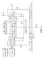
- Fig. 1 is a front view of a spray coating device according to an example disclosed hereinafter.
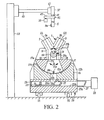
- Fig. 2 is a cross-sectional view taken along line A-A in Fig. 1.
- the spray coating device has a spray gun 5 from which a spray material is discharged for forming sprayed coatings on inner surfaces of cylinder bores 3a, 3b included in a cylinder block 1 of a V-type engine for a vehicle.
- the spray gun 5 and components for supporting the spray gun 5 are shown in Fig. 2.
- the cylinder block 1 of a V-type engine has a first bank 7 and a second bank 9.
- the first bank 7 is a cylinder bank having a plurality of the cylinder bores 3a arranged in a direction perpendicular to the page in Fig. 2 (i.e., an axial direction of a crankshaft).
- the second bank 9 is another cylinder bank having a plurality of the cylinder bores 3b arranged in the direction perpendicular to the page in Fig. 2 (i.e., the axial direction of the crankshaft).
- the cylinder bores 3a, 3b of the cylinder block 1 have respective axis lines SL, SR that intersect with each other when viewed in the axial direction of the crankshaft.
- the cylinder block 1 has a skirt portion 11 at a lower section thereof, which is fixedly joined to a crank casing 13 disposed therebelow.
- the skirt portion 11 and the crank casing 13 have a shaft bearing 15 therebetween for rotatably supporting the crankshaft.
- the crankshaft is not installed in the cylinder block 1.
- the rotator 17 has a flat upper surface 17a on which the crank casing 13 is secured and a rounded surface 17b that is convex downward.
- the rotator 17 is disposed on a rotator-holding base 19 whose upper side is provided with a concave rounded surface 19a that corresponds to the convex rounded surface 17b.
- the convex rounded surface 17b and the concave rounded surface 19a form a circular arc around a rotational axis X of the crankshaft disposed in the shaft bearing 15.
- the rotator 17 rotates around the rotational axis X in directions indicated by a double-headed arrow B in Fig. 2, thus tilting the cylinder block 1 above the rotator 17 in the same manner.
- left and right end portions of the rotator 17 are projected respectively in the left and right directions with respect to the cylinder block 1.
- Sections of the upper surface 17a that correspond to these projected portions have tilt shafts 21 connected thereto.
- Each tilt shaft 21 has a vertical segment 21 a extending upward from the upper surface 17a in Fig. 1 and a horizontal segment 21b extending horizontally away from the cylinder block 1 from an upper end of the vertical portion 21a.
- a central axis of the horizontal segment 21b is aligned with the rotational axis X.
- the rotator-holding base 19 is fixed on a bottom surface 23a of a table 23.
- the bottom surface 23a has side walls 23b extending upward from left and right sides thereof as shown in Fig. 1.
- the ends of the horizontal segments 21b of the tilt shafts 21 are rotatably connected to upper sections of the corresponding side walls 23b.
- a clearance gap 24 which is shown in an enlarged view in Fig. 3, is formed entirely between the convex rounded surface 17b of the rotator 17 and the concave rounded surface 19a of the rotator-holding base 19.
- the clearance gap 24 may be a narrow gap that allows air to flow through so that a rotator-holding-base communication hole 19b can communicate with the outside.
- the left tilt shaft 21 has its horizontal segment 21b extending rotatably through a rotational supporting hole 23c provided in the corresponding side wall 23b such that an end of the horizontal segment 21b protrudes outward.
- This protruding end is connected to a motor M serving as driving means.
- the motor M when the motor M is driven, the cylinder block 1 is tilted together with the rotator 17 around the rotational axis X within the shaft bearing 15 in one of the directions of the double-headed arrow B in Fig. 2.
- the motor M is connected to a controller C serving as controlling means for controlling the driving operation of the motor M.
- the controller C drives the motor M
- the cylinder block 1 can be rotated clockwise from the position in Fig. 2 so that the cylinder bores 3a of the first bank 7 face upward in the vertical direction as in Fig. 4A.
- the cylinder block 1 can be rotated counterclockwise from the position in Fig. 2 so that the cylinder bores 3b of the second bank 9 face upward in the vertical direction as in Fig. 4B.
- a central portion of the rotator-holding base 19 in the horizontal direction in Fig. 2 has the rotator-holding-base communication hole 19b, which serves as a through hole extending in the vertical direction.
- the rotator-holding-base communication hole 19b has an upper opening 19c, which is adjacent to the rounded surface 19a and communicates with a rotator communication hole 17c serving as a through hole of the rotator 17.
- the rotator communication hole 17c increases in width in the downward direction as shown in Fig. 2 so that even when the cylinder block 1 is tilted to the positions shown in Figs. 4A and 4B, a lower opening 17d of the rotator communication hole 17c is constantly in partial communication with the upper opening 19c of the rotator-holding-base communication hole 19b.
- the upper opening 19c of the rotator-holding-base communication hole 19b may be given a width larger than that of the lower opening 17d of the rotator communication hole 17c in the horizontal direction in Fig. 2. Consequently, the rotator communication hole 17c and the rotator-holding-base communication hole 19b are maintained in communication with each other even when the cylinder block 1 is tilted to the positions shown in Figs. 4A and 4B.
- one of the openings is wider than the other opening in the rotational direction of the rotator 17.
- the widths of the rotator communication hole 17c and the rotator-holding-base communication hole 19b in the horizontal direction in Fig. 1 are set smaller than the length of the cylinder block 1 in the same horizontal direction, such that the left and right internal sides of each hole are positioned within left and right external sides of the cylinder block 1.
- the rotator-holding-base communication hole 19b has a lower opening 19d that communicates with an exhaust channel 25 provided inside the table 23.
- the exhaust channel 25 has a communication portion 25a that directly communicates with the lower opening 19d of the rotator-holding-base communication hole 19b.
- the exhaust channel 25 also has an exhaust-channel portion 25b that communicates with a lower end of the communication portion 25a and extends in the horizontal direction as shown in Fig. 2.
- the exhaust-channel portion 25b has an external opening at the right end thereof in Fig. 2. This external opening is connected to an exhaust pipe 27.
- the exhaust pipe 27 is connected to an exhaust device 28 serving as exhaust means including, for example, a fan.
- the left end of the exhaust-channel portion 25b in Fig. 2 is covered with a lid 29, which can be opened and closed.
- a foreign-matter dropping plate 31 On the right side of the communication portion 25a of the exhaust channel 25 in Fig. 2 is provided a foreign-matter dropping plate 31 that is disposed at an angle.
- a foreign-matter receiving plate 33 is disposed on a bottom surface of the exhaust-channel portion 25b below the foreign-matter dropping plate 31. Together, the foreign-matter dropping plate 31 and the foreign-matter receiving plate 33 are used to remove foreign matter, such as scattered waste material from the exhaust channel 25. The foreign-matter receiving plate 33, and its contents, can be ejected outward by opening the lid 29.
- the table 23 is movable along one or more guide rails 35 in the horizontal direction with respect to Fig. 1 (i.e., in the longitudinal direction of the rotational axis X).
- the spray gun 5 has its upper portion connected to and is rotatably supported by a gun supporter 37 as shown in Fig. 2.
- the spray gun 5 is rotatable by means of a rotary driving motor 39.
- the gun supporter 37 for the spray gun 5 has a driven pulley 41 disposed around the periphery thereof.
- the rotary driving motor 39 is connected to a driving pulley 43.
- the pulleys 41 and 43 are connected to each other with a connector belt 45. In other words, when the rotary driving motor 39 is driven the spray gun 5 is rotated with respect to the gun supporter 37.
- the gun supporter 37 is provided with a lifting-lowering device 47 for moving the gun supporter 37 together with the spray gun 5 and the rotary driving motor 39 in the vertical direction in Fig. 2.
- the lifting-lowering device 47 may be, for example, a pinion and a rack.
- the lifting-lowering device 47 is connected to an end of a connector arm 49 that extends in the horizontal direction.
- the connector arm 49 has a base end that is attached to an upper section of a supporting post 53 extending vertically along a side of the table 23 as shown in Fig. 2.
- the gun supporter 37 and the rotary driving motor 39 for rotating the spray gun 5 are fixedly connected to each other with a fixing member, not shown, and are movable together in the vertical direction.
- the rotary driving motor 39 and the lifting-lowering device 47 are also driven by the controller C.
- Figs. 1 and 2 in a state where the upper surface 17a of the rotator 17 is set horizontally, the cylinder block 1 is set on the upper surface 17a and is secured thereon with the securing member 18 in step S1.
- step S2 the controller C drives the motor M so that the tilt shafts 21 are rotated clockwise with reference to Fig. 2 about the horizontal segments 21b thereof.
- the rotator 17 is rotated such that the convex rounded surface 17b thereof moves along the concave rounded surface 19a of the rotator-holding base 19. Consequently, referring to Fig. 4A, the cylinder block 1 rotates together with the rotator 17, whereby the cylinder bores 3a of the first bank 7 faces upward in the vertical direction.
- the spray gun 5 is rotated in step S3 by driving the rotary driving motor 39 and is simultaneously lowered by driving the lifting-lowering device 47 so that the spray gun 5 enters the cylinder bore 3a in the first bank 7.
- the spray gun 5 then discharges a spray material from a nozzle 5a thereof so as to form a sprayed coating on the inner surface of the cylinder bore 3a.
- the spray gun 5 is lifted for movement to the next cylinder bore 3a in the first bank 7 in step S4. If the plurality of cylinder bores 3a have been spray coated in response to the query of step S5, the procedure continues to step S7.
- the table 23 may be shifted together with the cylinder block 1 in the horizontal direction in Fig. 1 to position the spray gun 5 sequentially above each one of the cylinder bores 3a in step S6.
- the spray gun 5 may be shifted in the horizontal direction in Fig. 1 instead of the table 23. Steps S4, S5 and S6 are repeated until the discharge processes for each of the cylinder bores 3a are completed as indicated by the response to the query of step S5.
- the spray gun 5 is pulled out from the last cylinder bore 3a having the sprayed coating formed thereon and is lifted upward to the position shown in Fig. 4A.
- the controller C shown in Fig. 1 drives the motor M so that the tilt shafts 21 are rotated counterclockwise in Fig. 4A about the horizontal segments 21b thereof in step S7.
- the rotation angle corresponds to an intersection angle ⁇ formed between the axis lines SL, SR of the cylinder bores 3a, 3b as shown in Fig. 2.
- step S8 the spray gun 5 is positioned vertically above one of the cylinder bores 3b. In this state, shown in Fig. 4B, the center of rotation of the spray gun 5 is aligned with the axis line SR of the cylinder bore 3b.
- step S9 the spray gun 5 is rotated and simultaneously lowered in the same manner as above so that the spray gun 5 enters the cylinder bore 3b in the second bank 9.
- the spray gun 5 then discharges a spray material from the nozzle 5a thereof so as to form a sprayed coating on the inner surface of the cylinder bore 3b in step S10.
- the spray gun 5 is lifted for movement to the next cylinder bore 3b in the second bank 9. If the plurality of cylinder bores 3b has been spray coated, indicated by a "yes" response to the query of step S11, the procedure is completed in step S13.
- the table may be shifted together with the cylinder block in the horizontal direction shown in Figure 1 to position the spray gun 5 sequentially above each one of the cylinder bores 3b in step S12 to repeat steps S10 and S11 for each bore 3b.
- the motor M switches the position of the cylinder block 1 in the rotational direction, which is supported by the rotator 17, between a first spraying position and a second spraying position.
- the first spraying position corresponds to a position at which the spray gun 5 enters each of the cylinder bores included in one of at least two cylinder banks and discharges a spray material to form a sprayed coating for the cylinder bore.
- the second spraying position corresponds to a position at which the spray gun 5 enters each of the cylinder bores included in the other cylinder bank and discharges a spray material to form a sprayed coating for the cylinder bore.
- the spray coating process for forming sprayed coatings on the inner surfaces of the cylinder bores 3a, 3b simply involves rotating the cylinder block 1 by the intersection angle ⁇ and discharging a spray material towards the cylinder bores 3a, 3b using a single spray gun 5.
- the previously-known re-setup step for changing the mounting position of the cylinder block 1 is not required.
- the exhaust device 28 when forming sprayed coatings for the cylinder bores 3a, 3b, the exhaust device 28 is actuated so that the air in the cylinder bores 3a, 3b is drawn towards the exhaust pipe 27 by suction for ventilation. Ventilation air enters the cylinder bores 3a, 3b from the outside, travels through the rotator communication hole 17c and the rotator-holding-base communication hole 19b, and then passes through the exhaust channel 25 inside the table 23 so as to reach the exhaust pipe 27.
- a portion of the spray material discharged from the nozzle 5a may scatter without adhering to the cylinder bores 3a, 3b. However, this scattering portion of the spray material travels downward with the ventilation air, hits against the foreign-matter dropping plate 31, and then falls on the foreign-matter receiving plate 33.
- the foreign matter on the foreign-matter receiving plate 33 is discarded as a waste material by opening the lid 29 and ejecting the foreign-matter receiving plate 33.
- the clearance gap 24 between the rotator 17 and the rotator-holding base 19 draws in ambient air as shown in Fig. 3.
- the ambient air then travels through the rotator-holding-base communication hole 19b so as to flow into the exhaust channel 25.
- the clearance gap 24 is disposed between the convex rounded surface 17b of the rotator 17 and the concave rounded surface 19a of the rotator-holding base 19, the clearance gap 24 can be constantly maintained even during the rotation of the rotator 17.
- the clearance gap 24 can be made narrower so that foreign matter can be further prevented from entering the gap.
- the rotator communication hole 17c and the rotator-holding-base communication hole 19b are kept in communication with each other whether the cylinder block 1 is positioned at the first spraying position for spraying against the cylinder bores 3a of the first bank 7 or at the second spraying position for spraying against the cylinder bores 3b of the second bank 9. Therefore, the flow of exhaust air can be constantly maintained during a spray coating process.
- one of the openings is wider than the other opening in the rotational direction of the rotator 17 so that the rotator communication hole 17c and the rotator-holding-base communication hole 19b are constantly in communication with each other. Accordingly, by simply increasing the size of one of the through holes, the flow of exhaust air can be constantly maintained during a spray coating process.
- An angle formed between the first bank 7 and the second bank 9 constituting a V-type engine that is, the angle ⁇ formed between the axis lines SL, SR of the cylinder bores 3a, 3b, may be between 60° or 90° by example, but it could be smaller or larger, up to 180° in the case of a horizontally-opposed engine.
Landscapes
- Cylinder Crankcases Of Internal Combustion Engines (AREA)
- Pistons, Piston Rings, And Cylinders (AREA)
- Spray Control Apparatus (AREA)
- Coating By Spraying Or Casting (AREA)
Abstract
Description
- The present invention relates to a spray coating apparatus and method and particularly, but not exclusively, to an apparatus and method for forming sprayed coatings on inner surfaces of cylinder bores. Aspects of the invention also relate to a spray coating device, to an engine and to a vehicle.
-
Japanese Unexamined Patent Application Publication No. 8-246944 - It is an aim of the invention to improve upon known technology. Other aims and advantages of the invention will become apparent from the following description, claims and drawings.
- Aspects of the invention therefore provide an apparatus, a method and an engine as claimed in the appended claims.
- According to another aspect of the invention there is provided a spray coating device for forming sprayed coatings on inner surfaces of at least two cylinder bores included in an engine having a cylinder block, the at least two cylinder bores orientated in different directions with respect to an axis for a crankshaft, the device comprising a spray gun operable to enter respective ones of the at least two cylinder bores, a rotator supporting the cylinder block in a rotatable fashion around the axis for the crankshaft and a driving device operable to rotate the rotator and the cylinder block supported by the rotator about the axis for the crankshaft and between a first spraying position and a second spraying position, the first spraying position corresponding to a first one of the different directions and the second spraying position corresponding to a second one of the different directions.
- In an embodiment, the engine is one of a V-type engine and a horizontally-opposed engine having two banks with at least one cylinder bore in each bank.
- In an embodiment, the rotator has a convex rounded surface facing a rotator-holding base and the rotator-holding base has a concave rounded surface corresponding to the convex rounded surface of the rotator; and wherein a clearance gap is defined between the convex and concave rounded surfaces.
- The device may comprise a rotator through hole in the rotator, a base through hole in a rotator-holding base disposed opposite to the cylinder block from the rotator, an exhaust channel located in the rotator-holding base wherein the rotator through hole and the base through hole form a path for air to the exhaust channel when the cylinder block is positioned in each of the first spraying position and the second spraying position and an exhaust device coupled to an end of the exhaust channel, the exhaust device operable to suction air from a cylinder bore being sprayed through the path and the exhaust channel.
- The device may comprise a rotator opening in the rotator through hole of the rotator and a base opening in the base through hole of the rotator-holding base facing the rotator opening; and wherein one of the rotator opening and the base opening is wider than the other of the rotator opening and the base opening in a rotational direction of the rotator.
- In an embodiment, the device comprises a clearance gap between the rotator and the rotator-holding base, the clearance gap in communication with the base through hole.
- The rotator may have a convex rounded surface facing the rotator-holding base. The rotator-holding base may have a concave rounded surface corresponding to the convex rounded surface of the rotator; and wherein the clearance gap is between the convex and concave rounded surfaces.
- In an embodiment, the convex and concave rounded surfaces each form a round shape around the rotational axis.
- The device may comprise a receiving plate disposed in the exhaust channel for receiving scattered waste material.
- In an embodiment, the device comprises a dropping plate mounted above the receiving plate and extending in an angular direction toward the receiving plate for directing the scattered waste material to the receiving plate.
- According to another aspect of the invention there is provided a spray coating device for forming sprayed coatings on inner surface of at least two cylinder bores included in an engine having a cylinder block, the at least two cylinder bores orientated in different directions with respect to a rotational axis for a crankshaft, the device comprising means for discharging spray material in a predetermined direction for entering each of the cylinder bores, means for rotatably supporting the cylinder block about the rotational axis for the crankshaft and means for rotating the cylinder block around the rotational axis between a first spraying position and a second spraying position.
- According to a further aspect of the invention there is provided a method of forming sprayed coatings on inner surfaces of at least two cylinder bores included in an engine having a cylinder block, the at least two cylinder bores orientated in different directions with respect to a crankshaft, the method comprising discharging a spray material from a spray gun toward an inner surface of a first of the at least two cylinder bores so as to form a sprayed coating on the inner surface of the first of the at least two cylinder bores, rotating the cylinder block around a rotational axis through the cylinder block, the rotational axis associated with the crankshaft and discharging the spray material from the spray gun toward an inner surface of a second of the at least two cylinder bores so as to form the sprayed coating on the inner surface of the second of the at least two cylinder bores.
- In an embodiment, the engine is one of a V-type engine and a horizontally-opposed engine having at least two banks, the at least two cylinder bores split between the at least two banks.
- The method may comprise shifting one of the cylinder block and the spray gun in an axial direction of the rotational axis after discharging the spray material toward the inner surface of the first of the at least two cylinder bores.
- The method may comprise discharging the spray material from the spray gun toward an inner surface of a third of the at least two cylinder bores after the shifting step for forming a sprayed coating on the inner surface of the third of the at least two cylinder bores.
- In an embodiment, rotating the cylinder block around the rotational axis occurs after discharging the spray material from the spray gun toward the inner surface of the third of the at least two cylinder bores.
- In an embodiment, the method comprises exhausting air contained in the cylinder bores through a rotator through hole in the rotator and a base through hole in a rotator-holding base disposed opposite to the cylinder block, the rotator through hole and the base through hole forming a path, receiving the air in an exhaust channel from the path and discharging the air from the exhaust channel.
- In an embodiment, the method comprises receiving scattered waste material from the spray material into a receiving plate disposed in the exhaust channel.
- The method may comprise directing the scattered waste material to the receiving plate via a dropping plate extending angularly above the receiving plate.
- For example, a spray coating device for forming sprayed coatings on inner surfaces of at least two cylinder bores included in an engine having a cylinder block is taught herein. The at least two cylinder bores are orientated in different directions with respect to an axis for a crankshaft. The device comprises a spray gun operable to enter respective ones of the at least two cylinder bores, a rotator supporting the cylinder block in a rotatable fashion around the axis for the crankshaft and a driving device operable to rotate the rotator and the cylinder block supported by the rotator about the axis for the crankshaft and between a first spraying position and a second spraying position. The first spraying position corresponds to a first one of the different directions, and the second spraying position corresponds to a second one of the different directions.
- Methods for forming sprayed coatings on inner surfaces of at least two cylinder bores included in an engine having a cylinder block where the at least two cylinder bores are orientated in different directions with respect to a crankshaft are also taught herein. One such method comprises discharging a spray material from a spray gun toward an inner surface of a first of the at least two cylinder bores so as to form a sprayed coating on the inner surface of the first of the at least two cylinder bores, rotating the cylinder block around a rotational axis through the cylinder block, the rotational axis associated with the crankshaft, and discharging the spray material from the spray gun toward an inner surface of a second of the at least two cylinder bores so as to form the sprayed coating on the inner surface of the second of the at least two cylinder bores.
- According to another aspect of the invention there is provided a vehicle having an engine comprising at least two cylinders spray coated using the device or method set out in the preceding paragraphs.
- Within the scope of this application it is envisaged that the various aspects, embodiments and alternatives set out in the preceding paragraphs, in the claims and in the following description may be taken individually or in any combination thereof.
- The present invention will now be described, by way of example only, with reference to the accompanying drawings in which:
- Fig. 1 is a front view of a spray coating device according to an embodiment of the invention;
- Fig. 2 is a cross-sectional view taken along line A-A in Fig. 1;
- Fig. 3 illustrates air flowing through a clearance gap between a rotator and a rotator-holding base;
- Figs. 4A and 4B are cross-sectional views corresponding to Fig. 2 wherein Fig. 4A shows a state where a spray coating process is performed on one of cylinder bores included in a first bank, and Fig. 4B shows a state where a spray coating process is performed on one of cylinder bores included in a second bank; and
- Fig. 5 is a flow chart showing the procedure for spray coating the cylinder bores located in at least two separate banks.
- For certain engines, such as a V-type engine for example, performing a spray coating process (a thermal splay coating process) on cylinder bores in each of cylinder banks using a single conventional spray gun requires a re-setup step for changing the mounting position of a cylinder block on the base of the device in order to correspond to the vertically movable spray gun. This results in low workability.
- Referring now to the drawings of Figs. 1-5, shown are a spray coating device and method that increases workability. Fig. 1 is a front view of a spray coating device according to an example disclosed hereinafter. Fig. 2 is a cross-sectional view taken along line A-A in Fig. 1. The spray coating device has a
spray gun 5 from which a spray material is discharged for forming sprayed coatings on inner surfaces of cylinder bores 3a, 3b included in acylinder block 1 of a V-type engine for a vehicle. Thespray gun 5 and components for supporting thespray gun 5 are shown in Fig. 2. - Referring now to Fig. 2, the
cylinder block 1 of a V-type engine has afirst bank 7 and asecond bank 9. Thefirst bank 7 is a cylinder bank having a plurality of the cylinder bores 3a arranged in a direction perpendicular to the page in Fig. 2 (i.e., an axial direction of a crankshaft). Thesecond bank 9 is another cylinder bank having a plurality of the cylinder bores 3b arranged in the direction perpendicular to the page in Fig. 2 (i.e., the axial direction of the crankshaft). - Specifically, the cylinder bores 3a, 3b of the
cylinder block 1 have respective axis lines SL, SR that intersect with each other when viewed in the axial direction of the crankshaft. - The
cylinder block 1 has askirt portion 11 at a lower section thereof, which is fixedly joined to a crankcasing 13 disposed therebelow. Theskirt portion 11 and thecrank casing 13 have a shaft bearing 15 therebetween for rotatably supporting the crankshaft. When performing a spray coating process, the crankshaft is not installed in thecylinder block 1. - With the
crank casing 13 disposed on the bottom side, thecylinder block 1 is secured above arotator 17 by means of asecuring member 18. Therotator 17 has a flatupper surface 17a on which thecrank casing 13 is secured and arounded surface 17b that is convex downward. Therotator 17 is disposed on a rotator-holding base 19 whose upper side is provided with a concaverounded surface 19a that corresponds to the convexrounded surface 17b. - The convex
rounded surface 17b and the concaverounded surface 19a form a circular arc around a rotational axis X of the crankshaft disposed in the shaft bearing 15. Therotator 17 rotates around the rotational axis X in directions indicated by a double-headed arrow B in Fig. 2, thus tilting thecylinder block 1 above therotator 17 in the same manner. - Referring again to Fig. 1, left and right end portions of the
rotator 17 are projected respectively in the left and right directions with respect to thecylinder block 1. Sections of theupper surface 17a that correspond to these projected portions havetilt shafts 21 connected thereto. Eachtilt shaft 21 has avertical segment 21 a extending upward from theupper surface 17a in Fig. 1 and a horizontal segment 21b extending horizontally away from thecylinder block 1 from an upper end of thevertical portion 21a. A central axis of the horizontal segment 21b is aligned with the rotational axis X. - On the other hand, the rotator-holding
base 19 is fixed on abottom surface 23a of a table 23. Thebottom surface 23a has side walls 23b extending upward from left and right sides thereof as shown in Fig. 1. The ends of the horizontal segments 21b of thetilt shafts 21 are rotatably connected to upper sections of the corresponding side walls 23b. - When the horizontal segments 21b of the
tilt shafts 21 are rotatably connected to the side walls 23b of the table 23, aclearance gap 24, which is shown in an enlarged view in Fig. 3, is formed entirely between the convexrounded surface 17b of therotator 17 and the concaverounded surface 19a of the rotator-holdingbase 19. Theclearance gap 24 may be a narrow gap that allows air to flow through so that a rotator-holding-base communication hole 19b can communicate with the outside. - Regarding the left and
right tilt shafts 21 in Fig. 1, theleft tilt shaft 21 has its horizontal segment 21b extending rotatably through a rotational supportinghole 23c provided in the corresponding side wall 23b such that an end of the horizontal segment 21b protrudes outward. This protruding end is connected to a motor M serving as driving means. In other words, when the motor M is driven, thecylinder block 1 is tilted together with therotator 17 around the rotational axis X within the shaft bearing 15 in one of the directions of the double-headed arrow B in Fig. 2. - Furthermore, the motor M is connected to a controller C serving as controlling means for controlling the driving operation of the motor M. When the controller C drives the motor M, the
cylinder block 1 can be rotated clockwise from the position in Fig. 2 so that the cylinder bores 3a of thefirst bank 7 face upward in the vertical direction as in Fig. 4A. Alternately, thecylinder block 1 can be rotated counterclockwise from the position in Fig. 2 so that the cylinder bores 3b of thesecond bank 9 face upward in the vertical direction as in Fig. 4B. - A central portion of the rotator-holding
base 19 in the horizontal direction in Fig. 2 has the rotator-holding-base communication hole 19b, which serves as a through hole extending in the vertical direction. The rotator-holding-base communication hole 19b has anupper opening 19c, which is adjacent to therounded surface 19a and communicates with arotator communication hole 17c serving as a through hole of therotator 17. Therotator communication hole 17c increases in width in the downward direction as shown in Fig. 2 so that even when thecylinder block 1 is tilted to the positions shown in Figs. 4A and 4B, alower opening 17d of therotator communication hole 17c is constantly in partial communication with theupper opening 19c of the rotator-holding-base communication hole 19b. - Alternatively, the
upper opening 19c of the rotator-holding-base communication hole 19b may be given a width larger than that of thelower opening 17d of therotator communication hole 17c in the horizontal direction in Fig. 2. Consequently, therotator communication hole 17c and the rotator-holding-base communication hole 19b are maintained in communication with each other even when thecylinder block 1 is tilted to the positions shown in Figs. 4A and 4B. - In other words, of the two facing openings of the
rotator communication hole 17c and the rotator-holding-base communication hole 19b both serving as through holes, one of the openings is wider than the other opening in the rotational direction of therotator 17. - The widths of the
rotator communication hole 17c and the rotator-holding-base communication hole 19b in the horizontal direction in Fig. 1 are set smaller than the length of thecylinder block 1 in the same horizontal direction, such that the left and right internal sides of each hole are positioned within left and right external sides of thecylinder block 1. - The rotator-holding-
base communication hole 19b has alower opening 19d that communicates with anexhaust channel 25 provided inside the table 23. Theexhaust channel 25 has acommunication portion 25a that directly communicates with thelower opening 19d of the rotator-holding-base communication hole 19b. - The
exhaust channel 25 also has an exhaust-channel portion 25b that communicates with a lower end of thecommunication portion 25a and extends in the horizontal direction as shown in Fig. 2. The exhaust-channel portion 25b has an external opening at the right end thereof in Fig. 2. This external opening is connected to an exhaust pipe 27. The exhaust pipe 27 is connected to anexhaust device 28 serving as exhaust means including, for example, a fan. Thus, when a spray coating process is performed, the air in the cylinder bores 3a, 3b is drawn towards the exhaust pipe 27 by suction for ventilation. - The left end of the exhaust-
channel portion 25b in Fig. 2 is covered with alid 29, which can be opened and closed. - On the right side of the
communication portion 25a of theexhaust channel 25 in Fig. 2 is provided a foreign-matter dropping plate 31 that is disposed at an angle. - Furthermore, a foreign-
matter receiving plate 33 is disposed on a bottom surface of the exhaust-channel portion 25b below the foreign-matter dropping plate 31. Together, the foreign-matter dropping plate 31 and the foreign-matter receiving plate 33 are used to remove foreign matter, such as scattered waste material from theexhaust channel 25. The foreign-matter receiving plate 33, and its contents, can be ejected outward by opening thelid 29. - The table 23 is movable along one or
more guide rails 35 in the horizontal direction with respect to Fig. 1 (i.e., in the longitudinal direction of the rotational axis X). - The
spray gun 5 has its upper portion connected to and is rotatably supported by agun supporter 37 as shown in Fig. 2. Thespray gun 5 is rotatable by means of arotary driving motor 39. Thegun supporter 37 for thespray gun 5 has a drivenpulley 41 disposed around the periphery thereof. On the other hand, therotary driving motor 39 is connected to a drivingpulley 43. Thepulleys connector belt 45. In other words, when therotary driving motor 39 is driven thespray gun 5 is rotated with respect to thegun supporter 37. - The
gun supporter 37 is provided with a lifting-loweringdevice 47 for moving thegun supporter 37 together with thespray gun 5 and therotary driving motor 39 in the vertical direction in Fig. 2. The lifting-loweringdevice 47 may be, for example, a pinion and a rack. The lifting-loweringdevice 47 is connected to an end of aconnector arm 49 that extends in the horizontal direction. Theconnector arm 49 has a base end that is attached to an upper section of a supportingpost 53 extending vertically along a side of the table 23 as shown in Fig. 2. - The
gun supporter 37 and therotary driving motor 39 for rotating thespray gun 5 are fixedly connected to each other with a fixing member, not shown, and are movable together in the vertical direction. - Furthermore, the
rotary driving motor 39 and the lifting-loweringdevice 47 are also driven by the controller C. - The operation of the spray coating device is now described with reference to the flow chart of Fig. 5. Referring to Figs. 1 and 2, in a state where the
upper surface 17a of therotator 17 is set horizontally, thecylinder block 1 is set on theupper surface 17a and is secured thereon with the securingmember 18 in step S1. - Then, in step S2 the controller C drives the motor M so that the
tilt shafts 21 are rotated clockwise with reference to Fig. 2 about the horizontal segments 21b thereof. Thusly, therotator 17 is rotated such that the convexrounded surface 17b thereof moves along the concaverounded surface 19a of the rotator-holdingbase 19. Consequently, referring to Fig. 4A, thecylinder block 1 rotates together with therotator 17, whereby the cylinder bores 3a of thefirst bank 7 faces upward in the vertical direction. - In the state shown in Fig. 4A, the
spray gun 5 is positioned vertically above one of the cylinder bores 3a. In this state, the center of rotation of thespray gun 5 is aligned with the axis line SL of thecylinder bore 3a. - From this state in Fig. 4A, the
spray gun 5 is rotated in step S3 by driving therotary driving motor 39 and is simultaneously lowered by driving the lifting-loweringdevice 47 so that thespray gun 5 enters the cylinder bore 3a in thefirst bank 7. Thespray gun 5 then discharges a spray material from anozzle 5a thereof so as to form a sprayed coating on the inner surface of thecylinder bore 3a. After eachcylinder bore 3a is spray coated, thespray gun 5 is lifted for movement to the next cylinder bore 3a in thefirst bank 7 in step S4. If the plurality of cylinder bores 3a have been spray coated in response to the query of step S5, the procedure continues to step S7. - Otherwise, in order to form sprayed coatings sequentially for the plurality of cylinder bores 3a (in this case, three
cylinder bores 3a) in thefirst bank 7, the table 23 may be shifted together with thecylinder block 1 in the horizontal direction in Fig. 1 to position thespray gun 5 sequentially above each one of the cylinder bores 3a in step S6. Thespray gun 5 may be shifted in the horizontal direction in Fig. 1 instead of the table 23. Steps S4, S5 and S6 are repeated until the discharge processes for each of the cylinder bores 3a are completed as indicated by the response to the query of step S5. - The
spray gun 5 is pulled out from the last cylinder bore 3a having the sprayed coating formed thereon and is lifted upward to the position shown in Fig. 4A. In this state, the controller C shown in Fig. 1 drives the motor M so that thetilt shafts 21 are rotated counterclockwise in Fig. 4A about the horizontal segments 21b thereof in step S7. - In this case, the rotation angle corresponds to an intersection angle α formed between the axis lines SL, SR of the cylinder bores 3a, 3b as shown in Fig. 2.
- Thus, the
rotator 17 is rotated such that the convexrounded surface 17b thereof moves along the concaverounded surface 19a of the rotator-holdingbase 19. Consequently, referring to Fig. 4B, thecylinder block 1 rotates together with therotator 17, whereby the cylinder bores 3b of thesecond bank 9 faces upward in the vertical direction. In the next step, step S8, thespray gun 5 is positioned vertically above one of the cylinder bores 3b. In this state, shown in Fig. 4B, the center of rotation of thespray gun 5 is aligned with the axis line SR of thecylinder bore 3b. - From this state in Fig. 4B, in step S9 the
spray gun 5 is rotated and simultaneously lowered in the same manner as above so that thespray gun 5 enters the cylinder bore 3b in thesecond bank 9. Thespray gun 5 then discharges a spray material from thenozzle 5a thereof so as to form a sprayed coating on the inner surface of the cylinder bore 3b in step S10. After eachcylinder bore 3b is spray coated, thespray gun 5 is lifted for movement to the next cylinder bore 3b in thesecond bank 9. If the plurality ofcylinder bores 3b has been spray coated, indicated by a "yes" response to the query of step S11, the procedure is completed in step S13. - Otherwise, that is when the response to the query of step S11 is "no," in order to spray coating sequentially for the plurality of cylinder bores 3b (in this case, three
cylinder bores 3b) in thesecond bank 9, the table may be shifted together with the cylinder block in the horizontal direction shown in Figure 1 to position thespray gun 5 sequentially above each one of the cylinder bores 3b in step S12 to repeat steps S10 and S11 for eachbore 3b. - In other words, in response to a command from the controller C, the motor M switches the position of the
cylinder block 1 in the rotational direction, which is supported by therotator 17, between a first spraying position and a second spraying position. In this case, the first spraying position corresponds to a position at which thespray gun 5 enters each of the cylinder bores included in one of at least two cylinder banks and discharges a spray material to form a sprayed coating for the cylinder bore. The second spraying position corresponds to a position at which thespray gun 5 enters each of the cylinder bores included in the other cylinder bank and discharges a spray material to form a sprayed coating for the cylinder bore. - Accordingly, the spray coating process for forming sprayed coatings on the inner surfaces of the cylinder bores 3a, 3b simply involves rotating the
cylinder block 1 by the intersection angle α and discharging a spray material towards the cylinder bores 3a, 3b using asingle spray gun 5. By using this method, the previously-known re-setup step for changing the mounting position of thecylinder block 1 is not required. - As mentioned above, when forming sprayed coatings for the cylinder bores 3a, 3b, the
exhaust device 28 is actuated so that the air in the cylinder bores 3a, 3b is drawn towards the exhaust pipe 27 by suction for ventilation. Ventilation air enters the cylinder bores 3a, 3b from the outside, travels through therotator communication hole 17c and the rotator-holding-base communication hole 19b, and then passes through theexhaust channel 25 inside the table 23 so as to reach the exhaust pipe 27. - In this case, a portion of the spray material discharged from the
nozzle 5a may scatter without adhering to the cylinder bores 3a, 3b. However, this scattering portion of the spray material travels downward with the ventilation air, hits against the foreign-matter dropping plate 31, and then falls on the foreign-matter receiving plate 33. - The foreign matter on the foreign-
matter receiving plate 33, such as this portion of the spray material, is discarded as a waste material by opening thelid 29 and ejecting the foreign-matter receiving plate 33. - Furthermore, since the air in the cylinder bores 3a, 3b is drawn towards the exhaust pipe 27 by suction for ventilation, the
clearance gap 24 between therotator 17 and the rotator-holdingbase 19 draws in ambient air as shown in Fig. 3. The ambient air then travels through the rotator-holding-base communication hole 19b so as to flow into theexhaust channel 25. - Consequently, this prevents foreign matter such as the spray material from entering the space between the
rotator 17 and the rotator-holdingbase 19, thereby contributing to a stable rotation of therotator 17. - Also, since the
clearance gap 24 is disposed between the convexrounded surface 17b of therotator 17 and the concaverounded surface 19a of the rotator-holdingbase 19, theclearance gap 24 can be constantly maintained even during the rotation of therotator 17. Theclearance gap 24 can be made narrower so that foreign matter can be further prevented from entering the gap. - The
rotator communication hole 17c and the rotator-holding-base communication hole 19b are kept in communication with each other whether thecylinder block 1 is positioned at the first spraying position for spraying against the cylinder bores 3a of thefirst bank 7 or at the second spraying position for spraying against the cylinder bores 3b of thesecond bank 9. Therefore, the flow of exhaust air can be constantly maintained during a spray coating process. - Of the two facing openings, i.e., through holes, of the
rotator communication hole 17c and the rotator-holding-base communication hole 19b, one of the openings is wider than the other opening in the rotational direction of therotator 17 so that therotator communication hole 17c and the rotator-holding-base communication hole 19b are constantly in communication with each other. Accordingly, by simply increasing the size of one of the through holes, the flow of exhaust air can be constantly maintained during a spray coating process. - An angle formed between the
first bank 7 and thesecond bank 9 constituting a V-type engine, that is, the angle α formed between the axis lines SL, SR of the cylinder bores 3a, 3b, may be between 60° or 90° by example, but it could be smaller or larger, up to 180° in the case of a horizontally-opposed engine. - Also, the above-described embodiments have been described in order to allow easy understanding of the present invention and do not limit the present invention. On the contrary, the invention is intended to cover various modifications and equivalent arrangements included within the scope of the appended claims, which scope is to be accorded the broadest interpretation so as to encompass all such modifications and equivalent structure as is permitted under the law.
- This application claims priority from
Japanese Patent Application Serial No. 2005- 356779, filed 9th December 2005 2006-218380, filed 10th August 2006
Claims (15)
- An apparatus for forming sprayed coatings on inner surface of at least two cylinder bores included in an engine having a cylinder block wherein the at least two cylinder bores are orientated in different directions with respect to a rotational axis for a crankshaft, the device comprising:means for discharging spray material in a predetermined direction for entering each of the cylinder bores;means for rotatably supporting the cylinder block about the rotational axis for the crankshaft; andmeans for rotating the cylinder block around the rotational axis between a first spraying position and a second spraying position.
- An apparatus as claimed in claim 1 comprising:a spray gun operable to enter respective ones of the at least two cylinder bores;a rotator supporting the cylinder block in a rotatable fashion around the axis for the crankshaft; anda driving device operable to rotate the rotator and the cylinder block supported by the rotator about the axis for the crankshaft and between a first spraying position and a second spraying position, the first spraying position corresponding to a first one of the different directions and the second spraying position corresponding to a second one of the different directions.
- An apparatus as claimed in claim 3 wherein the engine is one of a V-type engine and a horizontally-opposed engine having two banks with at least one cylinder bore in each bank.
- An apparatus as claimed in claim 2 or claim 3 wherein the rotator has a convex rounded surface facing a rotator-holding base and the rotator-holding base has a concave rounded surface corresponding to the convex rounded surface of the rotator; and wherein a clearance gap is defined between the convex and concave rounded surfaces.
- An apparatus as claimed in any of claims 2 to 4 comprising:a rotator through hole in the rotator;a base through hole in a rotator-holding base disposed opposite to the cylinder block from the rotator;an exhaust channel located in the rotator-holding base wherein the rotator through hole and the base through hole form a path for air to the exhaust channel when the cylinder block is positioned in each of the first spraying position and the second spraying position; andan exhaust device coupled to an end of the exhaust channel, the exhaust device being arranged to suction air from a cylinder bore being sprayed through the path and the exhaust channel.
- An apparatus as claimed in claim 5 comprising:a rotator opening in the rotator through hole of the rotator; anda base opening in the base through hole of the rotator-holding base facing the rotator opening; and wherein one of the rotator opening and the base opening is wider than the other of the rotator opening and the base opening in a rotational direction of the rotator.
- An apparatus as claimed in claim 5 or claim 6 comprising:a clearance gap between the rotator and the rotator-holding base, the clearance gap in communication with the base through hole.
- An apparatus as claimed in claim 7 comprising:a receiving plate disposed in the exhaust channel for receiving scattered waste material; anda dropping plate mounted above the receiving plate and extending in an angular direction toward the receiving plate for directing the scattered waste material to the receiving plate.
- A method of forming sprayed coatings on inner surfaces of at least two cylinder bores included in an engine having a cylinder block, the at least two cylinder bores being orientated in different directions with respect to a crankshaft, the method comprising:discharging a spray material from a spray gun toward an inner surface of a first of the at least two cylinder bores so as to form a sprayed coating on the inner surface of the first of the at least two cylinder bores;rotating the cylinder block around a rotational axis through the cylinder block, the rotational axis associated with the crankshaft; anddischarging the spray material from the spray gun toward an inner surface of a second of the at least two cylinder bores so as to form the sprayed coating on the inner surface of the second of the at least two cylinder bores.
- A method as claimed in claim 9 wherein the engine is one of a V-type engine and a horizontally-opposed engine having at least two banks, the at least two cylinder bores split between the at least two banks.
- A method as claimed in claim 9 or claim 10 comprising:shifting one of the cylinder block and the spray gun in an axial direction of the rotational axis after discharging the spray material toward the inner surface of the first of the at least two cylinder bores.
- A method as claimed in claim 11 comprising:discharging the spray material from the spray gun toward an inner surface of a third of the at least two cylinder bores after the shifting step for forming a sprayed coating on the inner surface of the third of the at least two cylinder bores.
- A method as claimed in any of claims 9 to 12 comprising:exhausting air contained in the cylinder bores through a rotator through hole in the rotator and a base through hole in a rotator-holding base disposed opposite to the cylinder block, the rotator through hole and the base through hole forming a path;receiving the air in an exhaust channel from the path; anddischarging the air from the exhaust channel.
- A method as claimed in claim 13 comprising:receiving scattered waste material from the spray material into a receiving plate disposed in the exhaust channel.
- An engine comprising at least two cylinders spray coated using the apparatus claimed in any of claims 1 to 8 and/or the method claimed in any of claims 9 to 14.
Applications Claiming Priority (2)
| Application Number | Priority Date | Filing Date | Title |
|---|---|---|---|
| JP2005356779 | 2005-12-09 | ||
| JP2006218380A JP4650371B2 (en) | 2005-12-09 | 2006-08-10 | Thermal spray coating forming method and thermal spray coating forming apparatus |
Publications (3)
| Publication Number | Publication Date |
|---|---|
| EP1795269A2 true EP1795269A2 (en) | 2007-06-13 |
| EP1795269A3 EP1795269A3 (en) | 2009-05-27 |
| EP1795269B1 EP1795269B1 (en) | 2011-11-30 |
Family
ID=37846886
Family Applications (1)
| Application Number | Title | Priority Date | Filing Date |
|---|---|---|---|
| EP06125659A Active EP1795269B1 (en) | 2005-12-09 | 2006-12-07 | Spray coating apparatus and method |
Country Status (4)
| Country | Link |
|---|---|
| US (1) | US7555837B2 (en) |
| EP (1) | EP1795269B1 (en) |
| JP (1) | JP4650371B2 (en) |
| CN (1) | CN1978696B (en) |
Cited By (5)
| Publication number | Priority date | Publication date | Assignee | Title |
|---|---|---|---|---|
| WO2010059080A1 (en) * | 2008-11-20 | 2010-05-27 | Volvo Aero Corporation | Method for coating an exhaust port and apparatus for performing the method |
| CN102107165A (en) * | 2011-01-18 | 2011-06-29 | 浙江瑞丰五福气动工具有限公司 | Air collection device for electric spray gun |
| RU2475312C2 (en) * | 2008-05-19 | 2013-02-20 | Рексам Беверидж Кэн Компани | Sprayer with dual servo drive and method of applying coatings by spraying |
| CN110586392A (en) * | 2019-10-10 | 2019-12-20 | 北京好运达智创科技有限公司 | Track board release agent spraying equipment |
| CN111229500A (en) * | 2019-12-17 | 2020-06-05 | 广东菲力绿色板业有限公司 | Spraying support for building decorative panel |
Families Citing this family (14)
| Publication number | Priority date | Publication date | Assignee | Title |
|---|---|---|---|---|
| JP4497086B2 (en) * | 2005-01-28 | 2010-07-07 | 日産自動車株式会社 | Cylinder block spraying masking method, masking apparatus and gas jet nozzle |
| JP4983372B2 (en) * | 2007-04-23 | 2012-07-25 | マツダ株式会社 | Engine processing method and apparatus |
| JP5320951B2 (en) * | 2008-10-02 | 2013-10-23 | 日産自動車株式会社 | Thermal spray coating forming apparatus and thermal spray coating forming method |
| JP5651922B2 (en) * | 2009-03-04 | 2015-01-14 | 日産自動車株式会社 | Cylinder block and thermal spray coating forming method |
| CN103341716B (en) * | 2013-07-22 | 2015-03-04 | 常熟建华模具科技股份有限公司 | Tool clamp structure matched with power device and used for spray welding of glass mold |
| CN103358077B (en) * | 2013-07-22 | 2015-03-25 | 常熟建华模具科技股份有限公司 | Revolving glass mold fixture device |
| ES2715875T3 (en) * | 2015-01-20 | 2019-06-06 | Sturm Maschinen & Anlagenbau Gmbh | Installation and procedure for the metal coating of a workpiece |
| JP6420778B2 (en) * | 2016-01-15 | 2018-11-07 | 株式会社スギノマシン | Excess thermal spray coating removal device, shield plate, and shield unit |
| CN107398394B (en) * | 2016-02-04 | 2019-08-30 | 浙江翊翔塑模股份有限公司 | Car deceleration device cover board lubricating grease automatically smears equipment |
| US10435779B2 (en) * | 2017-03-14 | 2019-10-08 | Ford Motor Company | Precision air flow routing devices and method for thermal spray coating applications |
| CN107400847B (en) * | 2017-09-07 | 2023-05-26 | 中国人民解放军陆军装甲兵学院 | A system and process for remanufacturing waste cylinder components of aviation piston engines |
| CN112317211A (en) * | 2020-10-28 | 2021-02-05 | 德清恒川新材料科技有限公司 | Surface spraying device for metal copper surface coating |
| CN116213202B (en) * | 2023-01-10 | 2025-10-17 | 齐耐润科技(上海)股份有限公司 | Inner hole coating equipment |
| CN118880271B (en) * | 2024-08-12 | 2025-04-15 | 成都国泰真空设备有限公司 | A roll-to-roll vacuum coating equipment |
Citations (2)
| Publication number | Priority date | Publication date | Assignee | Title |
|---|---|---|---|---|
| JPH08246944A (en) | 1995-03-08 | 1996-09-24 | Suzuki Motor Corp | Cylinder of internal combustion engine and manufacturing method thereof |
| US20030219545A1 (en) | 2002-04-04 | 2003-11-27 | Sulzer Metco Ag | Apparatus and a method for the thermal coating of a surface |
Family Cites Families (14)
| Publication number | Priority date | Publication date | Assignee | Title |
|---|---|---|---|---|
| GB1326116A (en) * | 1970-09-24 | 1973-08-08 | Saviem | Metallising machines |
| JPS543610A (en) * | 1977-06-09 | 1979-01-11 | Honda Motor Co Ltd | Pre.treatment of plasma jet of cylinder for internal combustion engine |
| US5080056A (en) * | 1991-05-17 | 1992-01-14 | General Motors Corporation | Thermally sprayed aluminum-bronze coatings on aluminum engine bores |
| US5573814A (en) * | 1995-10-30 | 1996-11-12 | Ford Motor Company | Masking cylinder bore extremities from internal thermal spraying |
| US5622753A (en) * | 1996-04-08 | 1997-04-22 | Ford Motor Company | Method of preparing and coating aluminum bore surfaces |
| US5958521A (en) * | 1996-06-21 | 1999-09-28 | Ford Global Technologies, Inc. | Method of depositing a thermally sprayed coating that is graded between being machinable and being wear resistant |
| US6395090B1 (en) * | 1999-08-16 | 2002-05-28 | Ford Global Technologies, Inc. | Masking for engine blocks for thermally sprayed coatings |
| DE50102898D1 (en) * | 2000-05-03 | 2004-08-26 | Sulzer Metco Ag Wohlen | Arrangement for protecting cylinder walls of engine blocks |
| JP3664377B2 (en) * | 2000-06-21 | 2005-06-22 | スズキ株式会社 | Cylinder spraying equipment |
| US6619645B1 (en) * | 2000-11-28 | 2003-09-16 | Rottler Manufacturing Inc. | Fixturing system for holding and aligning engine blocks during rebuilding |
| US6491293B1 (en) * | 2002-02-08 | 2002-12-10 | Michael L. Brewer | Rotatable engine holding assembly |
| US6719847B2 (en) | 2002-02-20 | 2004-04-13 | Cinetic Automation Corporation | Masking apparatus |
| DE10230847B3 (en) * | 2002-07-04 | 2004-02-05 | Universität Stuttgart Institut für Fertigungstechnologie keramischer Bauteile | Process and device for the internal coating of cavities by thermal spraying |
| JP4597053B2 (en) * | 2004-02-03 | 2010-12-15 | 本田技研工業株式会社 | Workpiece assembly apparatus and assembly method |
-
2006
- 2006-08-10 JP JP2006218380A patent/JP4650371B2/en active Active
- 2006-12-07 EP EP06125659A patent/EP1795269B1/en active Active
- 2006-12-07 US US11/635,141 patent/US7555837B2/en active Active
- 2006-12-08 CN CN2006101404008A patent/CN1978696B/en active Active
Patent Citations (2)
| Publication number | Priority date | Publication date | Assignee | Title |
|---|---|---|---|---|
| JPH08246944A (en) | 1995-03-08 | 1996-09-24 | Suzuki Motor Corp | Cylinder of internal combustion engine and manufacturing method thereof |
| US20030219545A1 (en) | 2002-04-04 | 2003-11-27 | Sulzer Metco Ag | Apparatus and a method for the thermal coating of a surface |
Cited By (7)
| Publication number | Priority date | Publication date | Assignee | Title |
|---|---|---|---|---|
| RU2475312C2 (en) * | 2008-05-19 | 2013-02-20 | Рексам Беверидж Кэн Компани | Sprayer with dual servo drive and method of applying coatings by spraying |
| WO2010059080A1 (en) * | 2008-11-20 | 2010-05-27 | Volvo Aero Corporation | Method for coating an exhaust port and apparatus for performing the method |
| EP2358920A4 (en) * | 2008-11-20 | 2012-04-11 | Volvo Aero Corp | Method for coating an exhaust port and apparatus for performing the method |
| CN102107165A (en) * | 2011-01-18 | 2011-06-29 | 浙江瑞丰五福气动工具有限公司 | Air collection device for electric spray gun |
| CN110586392A (en) * | 2019-10-10 | 2019-12-20 | 北京好运达智创科技有限公司 | Track board release agent spraying equipment |
| CN110586392B (en) * | 2019-10-10 | 2024-03-15 | 北京好运达智创科技有限公司 | Track slab release agent spraying equipment |
| CN111229500A (en) * | 2019-12-17 | 2020-06-05 | 广东菲力绿色板业有限公司 | Spraying support for building decorative panel |
Also Published As
| Publication number | Publication date |
|---|---|
| US20070130746A1 (en) | 2007-06-14 |
| EP1795269A3 (en) | 2009-05-27 |
| CN1978696A (en) | 2007-06-13 |
| EP1795269B1 (en) | 2011-11-30 |
| CN1978696B (en) | 2010-06-16 |
| JP4650371B2 (en) | 2011-03-16 |
| JP2007182621A (en) | 2007-07-19 |
| US7555837B2 (en) | 2009-07-07 |
Similar Documents
| Publication | Publication Date | Title |
|---|---|---|
| EP1795269B1 (en) | Spray coating apparatus and method | |
| US9101965B2 (en) | High-pressure washing liquid ejecting washing apparatus | |
| EP2230392A1 (en) | Cylinder head cleaning method and cylinder head cleaning device | |
| JPH11320414A (en) | Blasting method of inner surface of cylinder | |
| RU2694949C1 (en) | Cooling method of compressor or vacuum pump and compressor or vacuum pump, in which such method is used | |
| JP2016014381A (en) | Air compressor for vehicle | |
| EP3895926B1 (en) | Construction machine | |
| EP2255898A1 (en) | Fume suction unit | |
| KR20090100226A (en) | Apparatus for manufacturing fins for suction devices and heat exchangers | |
| JP2010138844A (en) | Lubricating oil cooling structure for engine | |
| JP5320951B2 (en) | Thermal spray coating forming apparatus and thermal spray coating forming method | |
| JP3380056B2 (en) | Engine mounted work machine | |
| KR20180054831A (en) | Cooling method of compressor or vacuum pump and compressor or vacuum pump applying this method | |
| US7534978B2 (en) | Process chamber of an installation for the thermal treatment of printed circuit boards | |
| JPH11239974A (en) | Sandblasting equipment | |
| JP3431810B2 (en) | Intake and exhaust valve drive control device for internal combustion engine | |
| JP2000345977A (en) | Scroll compressor | |
| JP5671089B2 (en) | Substrate processing apparatus and method | |
| JPH0918125A (en) | Flux coating device | |
| WO2022050312A1 (en) | Lubricating oil micronization prevention device | |
| KR100484244B1 (en) | Apparatus for controlling direction of wind in air conditioner | |
| KR100791969B1 (en) | Metal Laminate Manufacturing Equipment | |
| FI70550C (en) | ANORDING WITH BEARING | |
| KR200206434Y1 (en) | The rotary apparatus to inhale air in engine | |
| JP2004144099A (en) | Engine balancer device |
Legal Events
| Date | Code | Title | Description |
|---|---|---|---|
| PUAI | Public reference made under article 153(3) epc to a published international application that has entered the european phase |
Free format text: ORIGINAL CODE: 0009012 |
|
| AK | Designated contracting states |
Kind code of ref document: A2 Designated state(s): AT BE BG CH CY CZ DE DK EE ES FI FR GB GR HU IE IS IT LI LT LU LV MC NL PL PT RO SE SI SK TR |
|
| AX | Request for extension of the european patent |
Extension state: AL BA HR MK YU |
|
| PUAL | Search report despatched |
Free format text: ORIGINAL CODE: 0009013 |
|
| AK | Designated contracting states |
Kind code of ref document: A3 Designated state(s): AT BE BG CH CY CZ DE DK EE ES FI FR GB GR HU IE IS IT LI LT LU LV MC NL PL PT RO SE SI SK TR |
|
| AX | Request for extension of the european patent |
Extension state: AL BA HR MK RS |
|
| 17P | Request for examination filed |
Effective date: 20091102 |
|
| 17Q | First examination report despatched |
Effective date: 20091204 |
|
| AKX | Designation fees paid |
Designated state(s): DE FR GB |
|
| GRAP | Despatch of communication of intention to grant a patent |
Free format text: ORIGINAL CODE: EPIDOSNIGR1 |
|
| GRAS | Grant fee paid |
Free format text: ORIGINAL CODE: EPIDOSNIGR3 |
|
| GRAA | (expected) grant |
Free format text: ORIGINAL CODE: 0009210 |
|
| AK | Designated contracting states |
Kind code of ref document: B1 Designated state(s): DE FR GB |
|
| REG | Reference to a national code |
Ref country code: GB Ref legal event code: FG4D |
|
| REG | Reference to a national code |
Ref country code: DE Ref legal event code: R096 Ref document number: 602006026118 Country of ref document: DE Effective date: 20120301 |
|
| PLBE | No opposition filed within time limit |
Free format text: ORIGINAL CODE: 0009261 |
|
| STAA | Information on the status of an ep patent application or granted ep patent |
Free format text: STATUS: NO OPPOSITION FILED WITHIN TIME LIMIT |
|
| 26N | No opposition filed |
Effective date: 20120831 |
|
| REG | Reference to a national code |
Ref country code: DE Ref legal event code: R097 Ref document number: 602006026118 Country of ref document: DE Effective date: 20120831 |
|
| REG | Reference to a national code |
Ref country code: FR Ref legal event code: PLFP Year of fee payment: 10 |
|
| REG | Reference to a national code |
Ref country code: FR Ref legal event code: PLFP Year of fee payment: 11 |
|
| REG | Reference to a national code |
Ref country code: FR Ref legal event code: PLFP Year of fee payment: 12 |
|
| REG | Reference to a national code |
Ref country code: DE Ref legal event code: R084 Ref document number: 602006026118 Country of ref document: DE |
|
| REG | Reference to a national code |
Ref country code: GB Ref legal event code: 746 Effective date: 20230922 |
|
| PGFP | Annual fee paid to national office [announced via postgrant information from national office to epo] |
Ref country code: DE Payment date: 20251126 Year of fee payment: 20 |
|
| PGFP | Annual fee paid to national office [announced via postgrant information from national office to epo] |
Ref country code: GB Payment date: 20251119 Year of fee payment: 20 |
|
| PGFP | Annual fee paid to national office [announced via postgrant information from national office to epo] |
Ref country code: FR Payment date: 20251120 Year of fee payment: 20 |