EP1794748B1 - Datenverarbeitungsverfahren durch Übergang zwischen verschiedenen Subband-domänen - Google Patents
Datenverarbeitungsverfahren durch Übergang zwischen verschiedenen Subband-domänen Download PDFInfo
- Publication number
- EP1794748B1 EP1794748B1 EP05798240A EP05798240A EP1794748B1 EP 1794748 B1 EP1794748 B1 EP 1794748B1 EP 05798240 A EP05798240 A EP 05798240A EP 05798240 A EP05798240 A EP 05798240A EP 1794748 B1 EP1794748 B1 EP 1794748B1
- Authority
- EP
- European Patent Office
- Prior art keywords
- vector
- matrix
- filters
- bank
- conversion
- Prior art date
- Legal status (The legal status is an assumption and is not a legal conclusion. Google has not performed a legal analysis and makes no representation as to the accuracy of the status listed.)
- Ceased
Links
- 238000003672 processing method Methods 0.000 title 1
- 238000006243 chemical reaction Methods 0.000 claims abstract description 136
- 239000013598 vector Substances 0.000 claims abstract description 121
- 239000011159 matrix material Substances 0.000 claims abstract description 91
- 238000001914 filtration Methods 0.000 claims abstract description 28
- 238000012545 processing Methods 0.000 claims abstract description 25
- 238000000034 method Methods 0.000 claims description 85
- 238000004458 analytical method Methods 0.000 claims description 61
- 230000015572 biosynthetic process Effects 0.000 claims description 57
- 238000003786 synthesis reaction Methods 0.000 claims description 57
- 238000005070 sampling Methods 0.000 claims description 21
- 230000004044 response Effects 0.000 claims description 18
- 238000012546 transfer Methods 0.000 claims description 17
- 238000000354 decomposition reaction Methods 0.000 claims description 15
- 238000007906 compression Methods 0.000 claims description 12
- 230000006835 compression Effects 0.000 claims description 12
- 238000004891 communication Methods 0.000 claims description 11
- 230000008569 process Effects 0.000 claims description 10
- 230000006870 function Effects 0.000 claims description 9
- 238000012952 Resampling Methods 0.000 claims description 6
- 238000010276 construction Methods 0.000 claims description 4
- 230000001934 delay Effects 0.000 claims description 3
- 230000001364 causal effect Effects 0.000 claims description 2
- 238000004590 computer program Methods 0.000 claims description 2
- 230000001419 dependent effect Effects 0.000 claims 1
- 230000009466 transformation Effects 0.000 description 10
- OVOUKWFJRHALDD-UHFFFAOYSA-N 2-[2-(2-acetyloxyethoxy)ethoxy]ethyl acetate Chemical compound CC(=O)OCCOCCOCCOC(C)=O OVOUKWFJRHALDD-UHFFFAOYSA-N 0.000 description 9
- 230000008859 change Effects 0.000 description 9
- 230000014509 gene expression Effects 0.000 description 9
- 238000004364 calculation method Methods 0.000 description 8
- 235000021183 entrée Nutrition 0.000 description 8
- 238000011084 recovery Methods 0.000 description 8
- 230000005236 sound signal Effects 0.000 description 8
- 238000005266 casting Methods 0.000 description 6
- 238000010586 diagram Methods 0.000 description 6
- 101100536354 Drosophila melanogaster tant gene Proteins 0.000 description 4
- 101000591286 Homo sapiens Myocardin-related transcription factor A Proteins 0.000 description 4
- 102100034099 Myocardin-related transcription factor A Human genes 0.000 description 4
- 230000009467 reduction Effects 0.000 description 4
- 230000003595 spectral effect Effects 0.000 description 4
- 230000001629 suppression Effects 0.000 description 4
- 102100036305 C-C chemokine receptor type 8 Human genes 0.000 description 3
- 102100026191 Class E basic helix-loop-helix protein 40 Human genes 0.000 description 3
- 101710130550 Class E basic helix-loop-helix protein 40 Proteins 0.000 description 3
- 101000837299 Euglena gracilis Trans-2-enoyl-CoA reductase Proteins 0.000 description 3
- 101000716063 Homo sapiens C-C chemokine receptor type 8 Proteins 0.000 description 3
- 238000010719 annulation reaction Methods 0.000 description 3
- 230000005540 biological transmission Effects 0.000 description 3
- 238000004422 calculation algorithm Methods 0.000 description 3
- 238000013461 design Methods 0.000 description 3
- 230000000873 masking effect Effects 0.000 description 3
- 230000007246 mechanism Effects 0.000 description 3
- 238000013519 translation Methods 0.000 description 3
- 102100026190 Class E basic helix-loop-helix protein 41 Human genes 0.000 description 2
- 101000765033 Homo sapiens Class E basic helix-loop-helix protein 41 Proteins 0.000 description 2
- 230000008901 benefit Effects 0.000 description 2
- 230000000903 blocking effect Effects 0.000 description 2
- 238000011161 development Methods 0.000 description 2
- 230000018109 developmental process Effects 0.000 description 2
- 230000009977 dual effect Effects 0.000 description 2
- 238000005516 engineering process Methods 0.000 description 2
- 238000012986 modification Methods 0.000 description 2
- 230000004048 modification Effects 0.000 description 2
- 238000013139 quantization Methods 0.000 description 2
- 230000010076 replication Effects 0.000 description 2
- 230000002123 temporal effect Effects 0.000 description 2
- 230000007704 transition Effects 0.000 description 2
- 101150012579 ADSL gene Proteins 0.000 description 1
- 102100020775 Adenylosuccinate lyase Human genes 0.000 description 1
- 108700040193 Adenylosuccinate lyases Proteins 0.000 description 1
- 102000005717 Myeloma Proteins Human genes 0.000 description 1
- 108010045503 Myeloma Proteins Proteins 0.000 description 1
- 241001080024 Telles Species 0.000 description 1
- 230000006978 adaptation Effects 0.000 description 1
- 238000013459 approach Methods 0.000 description 1
- FQCKMBLVYCEXJB-MNSAWQCASA-L atorvastatin calcium Chemical compound [Ca+2].C=1C=CC=CC=1C1=C(C=2C=CC(F)=CC=2)N(CC[C@@H](O)C[C@@H](O)CC([O-])=O)C(C(C)C)=C1C(=O)NC1=CC=CC=C1.C=1C=CC=CC=1C1=C(C=2C=CC(F)=CC=2)N(CC[C@@H](O)C[C@@H](O)CC([O-])=O)C(C(C)C)=C1C(=O)NC1=CC=CC=C1 FQCKMBLVYCEXJB-MNSAWQCASA-L 0.000 description 1
- 230000015556 catabolic process Effects 0.000 description 1
- 238000007796 conventional method Methods 0.000 description 1
- 238000006731 degradation reaction Methods 0.000 description 1
- 238000009472 formulation Methods 0.000 description 1
- 238000007429 general method Methods 0.000 description 1
- 230000006872 improvement Effects 0.000 description 1
- 230000010354 integration Effects 0.000 description 1
- 238000012423 maintenance Methods 0.000 description 1
- 239000000203 mixture Substances 0.000 description 1
- 238000005457 optimization Methods 0.000 description 1
- 229920001690 polydopamine Polymers 0.000 description 1
- 238000012552 review Methods 0.000 description 1
- 230000002194 synthesizing effect Effects 0.000 description 1
- 238000000844 transformation Methods 0.000 description 1
- 230000017105 transposition Effects 0.000 description 1
Images


Classifications
-
- G—PHYSICS
- G10—MUSICAL INSTRUMENTS; ACOUSTICS
- G10L—SPEECH ANALYSIS TECHNIQUES OR SPEECH SYNTHESIS; SPEECH RECOGNITION; SPEECH OR VOICE PROCESSING TECHNIQUES; SPEECH OR AUDIO CODING OR DECODING
- G10L19/00—Speech or audio signals analysis-synthesis techniques for redundancy reduction, e.g. in vocoders; Coding or decoding of speech or audio signals, using source filter models or psychoacoustic analysis
- G10L19/02—Speech or audio signals analysis-synthesis techniques for redundancy reduction, e.g. in vocoders; Coding or decoding of speech or audio signals, using source filter models or psychoacoustic analysis using spectral analysis, e.g. transform vocoders or subband vocoders
- G10L19/0204—Speech or audio signals analysis-synthesis techniques for redundancy reduction, e.g. in vocoders; Coding or decoding of speech or audio signals, using source filter models or psychoacoustic analysis using spectral analysis, e.g. transform vocoders or subband vocoders using subband decomposition
-
- G—PHYSICS
- G10—MUSICAL INSTRUMENTS; ACOUSTICS
- G10L—SPEECH ANALYSIS TECHNIQUES OR SPEECH SYNTHESIS; SPEECH RECOGNITION; SPEECH OR VOICE PROCESSING TECHNIQUES; SPEECH OR AUDIO CODING OR DECODING
- G10L19/00—Speech or audio signals analysis-synthesis techniques for redundancy reduction, e.g. in vocoders; Coding or decoding of speech or audio signals, using source filter models or psychoacoustic analysis
- G10L19/04—Speech or audio signals analysis-synthesis techniques for redundancy reduction, e.g. in vocoders; Coding or decoding of speech or audio signals, using source filter models or psychoacoustic analysis using predictive techniques
- G10L19/16—Vocoder architecture
- G10L19/173—Transcoding, i.e. converting between two coded representations avoiding cascaded coding-decoding
Definitions
- the present invention relates to data processing by passing between different subband domains, including, but not exclusively, for transcoding between two types of compression coding / decoding.
- One of the main problems due to the heterogeneity of terminals concerns the diversity of coding formats that they are able to interpret.
- One possible solution would be to recover the capabilities of the terminal before delivering the content in a compatible format.
- This solution may be more or less effective depending on the delivery scenario of the multimedia content considered (download, streaming or broadcast). It becomes inapplicable in certain cases, as for broadcasting (or " broadcasting ”) or for streaming in multicast mode.
- the notion of transcoding (or changing the encoding format) is therefore important. This operation can take place at different levels of the transmission chain. It can intervene at the server to change the format of content previously stored for example in a database, or intervene in a gateway in the network, or other.
- a common and straightforward method of transcoding is to decode the content and recode it to obtain a representation in the new encoding format.
- This method generally has the drawbacks of using a large computing power, of increasing the algorithmic delay due to the processing and sometimes of adding further degradation of the perceptual quality of the multimedia signal. These settings are very important in multimedia applications. Their improvement (decrease in complexity and delay and quality maintenance) is an important factor in the success of these applications. This factor sometimes becomes an essential condition for implementation.
- transcoding In order to improve these parameters, the " intelligent " transcoding principle is born. This type of transcoding consists in performing a partial decoding, as minimal as possible, of the initial coding format to extract the parameters allowing the reconstruction of the new coding format. The success of this process It is therefore able to reduce algorithmic complexity and delay and to maintain or even increase perceptual quality.
- audio encoders There is a wide variety of audio encoders that have been designed for different types of applications and for a wide range of data rates and qualities. These encoders can be manufacturer-specific (or "proprietary "), or standardized by decision of international organizations. In addition, they all have a common basic structure and are based on the same principles.
- the basic principle of perceptual frequency audio coding is to reduce the flow of information by exploiting the properties of the human hearing system.
- the irrelevant components of the audio signal are eliminated.
- This operation uses the phenomenon called " masking ". Since the description of this masking effect is mainly in the frequency domain, the representation of the signal is carried out in the frequency domain.
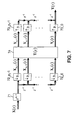
- the basic schemes of a coding and decoding system are presented on the Figures 2a and 2b .
- the input digital audio signal Se is first decomposed by an analysis filter bank 20.
- the resulting spectral components are then quantized and coded by the module 22.
- the quantization uses the result of a perceptual model 24 noise from the treatment is inaudible.
- a multiplexing of the different coded parameters is performed by the module 26 and an audio frame Sc is thus constructed.
- decoding is performed in a dual manner. After demultiplexing the audio frame by the module 21, the various parameters are decoded and the spectral components of the signal are de-quantized by the module 23.
- the temporal audio signal is reconstituted by the synthesis filterbank 25.
- the first stage of any perceptual audio coding system therefore consists of an analysis filter bank 20 used for the time / frequency transformation.
- filter banks and transforms have been developed and exploited in audio coders.
- pseudo-QMF filter banks, hybrid filter banks and MDCT transform banks may be mentioned.
- the MDCT transform is currently proving to be the most effective in this context. It is the basis of the latest and most powerful audio coding algorithms such as those used for MPEG-4 AAC, TwinVQ and BSAC, Dolby AC-3, in the TDAC coder / decoder (for " Time Domain Aliasing Cancellation "). ) of France Telecom, in ITU-T G.722.1.
- FIGs 3a and 3b respectively illustrate the conventional transcoding and intelligent transcoding schemes in a communication chain, between a coder CO1 according to a first coding format and a decoder DEC2 according to a second coding format.
- it is a question of performing a decoding operation complete by the decoder module DEC1 according to the first format ( figure 3a ), followed by a recoding by the CO2 encoder module according to the second format, to finally lead to the second coding format.
- Table 1 gives a summary of the types of filter banks used in the most well-known transform audio coders, as well as their characteristics. As can be seen, in addition to the MDCT transform which is the most used, there are Pseudo-QMF benches. Moreover, they are all part of the family of maximum decimation banks and modulated cosines verifying exactly or almost the perfect reconstruction property. ⁇ b> Table 1: The most used filter banks in audio coding and their characteristics.
- MPEG-1 Layer I & II Pseudo-QMF Number of bands M 32 MPEG-1 Layer III Pseudo-QMF / MDCT (Hybrid) 32 tapes followed by a MDCT of size 18 for each MPEG-2/4
- Table 2 below shows some types of subband coding in Table 1, detailing some of their applications.
- Table 2 Examples of subband encoders for audio and speech signals and some examples of their main applications.
- encoder applications Remarks MPEG-1/2 Layer I Broadcasting MPEG-1/2 Layer II Broadcasting Used in Europe for DAB broadcasting ("Digital Audio Broadcasting", ETSI ETS 300 401 standard).
- MPEG-1 Layer III (MP3) Download MPEG-1 Layer III (MP3) Download
- MPEG-2/4 AAC Broadcasting download
- the MPEG-2 AAC audio encoder (ISO / IEC13818-7) is specified as a single audio encoder for broadcast in Japan in Integrated Service Digital Broadcasting (ISDB) services including: - ISDB-T (terrestrial), - ISDB- S (satellite), - and ISDB-C (cable).
- ISDB Integrated Service Digital Broadcasting
- DVB-IP uses MPEG-2 AAC encoder MPEG-4 BSAC Broadcasting This encoder is used in Korea for digital TV broadcasting Dolby AC-3 Broadcasting Used in the USA for digital TV broadcasting Sony ATTRAC3 Used in Japan (online music channel of the iTunes type). France Telecom: TDAC teleconference ITU-T G.722 teleconference G.722.1 Teleconference, H.323 Group communication systems (teleconferencing, audio conferencing)
- TDF Tranform-Domain Filtering
- TDRT Transform-Domain Resolution Translation
- DCT for " Discrete Cosine Transform "
- MLT Modulated Lapped Transform
- TDAC filter banks are more convenient and more used in audio encoders, unlike DFT filter banks.
- performing an act or changes on the signal components in the transformed domain is neither adequate nor sufficiently flexible given the existence of aliasing components (or "aliasing").
- the DFT representation is more useful when it comes to making changes to the audio signal such as a time scale change or a pitch shift.
- This reference therefore proposes a direct conversion method between MDCT domain and DFT instead of applying the conventional method of synthesizing the time signal by an inverse MDCT, and then applying the DFT. This method makes it possible to carry out modifications directly in the coded domain.
- the document also proposes the dual conversion method between the DFT and MDCT domains that would be useful in case there is a need to recode the audio signal after modification.
- This publication discloses an efficient structure for implementing a system of a synthesis filter bank, at L sub-bands, followed by a bank of M -subband analysis filters, where M and L are multiple one of the other.
- This structure is effective for implementation in VLSI technology (" Very Large Scale Integration ") or FPGA (" Field Programmable Gate Array ”) or parallel processors. It requires fewer logic blocks, low power consumption and allows the degree of parallelism to be extended.
- the proposed method is applicable in situations where subband-based processing follows another subband treatment and where the synthesized intermediate signal is not needed.
- the present invention improves the situation with respect to the state of the art presented above.
- the present invention proposes in particular, but not exclusively, as will be seen below, a transcoding of a first type of coding, any, to a second type of coding, any.
- the respective numbers of M and L sub-bands are any natural numbers and are not necessarily linked by a proportionality relation, in the most general case.
- the present invention also relates to a computer program product as defined in claim 26, intended to be stored in a memory of a device in a communication network, such as a server, a gateway, or a terminal, and comprising then instructions for the implementation of all or part of the method according to the invention.
- the present invention also relates to equipment as defined in claim 27, such as a server, a gateway, or a terminal, intended for a communication network, and comprising computing resources for implementing the method according to the invention. invention.
- the L- band synthesis bench used by a first compression coding system and defined by its filters, denoted F k ( z ), 0 k k ⁇ L -1, and the analysis filter bank at M are considered.
- the two banks of filters used in the two compression systems are supposed to be preferentially at maximum decimation (or " critical sampling "), as will be seen below.
- the schema of the figure 5a can be represented by that of the figure 6 , on which an analysis filter bank follows a synthesis filter bank.
- the L- sub-band synthesis filter bank is conventionally composed in each sub-band k, 0 k k ⁇ L -1, of an oversampling operation by a factor L followed by a filtering by the filter of synthesis F k ( z ).
- the subband signal corresponding to the kth component of the input vector X ( z ) is therefore first oversampled and then filtered by the filter F k ( z ).
- the time signal, X ( z ), synthesized at the output of this synthesis bank is then obtained by summing the results of these filterings for 0 k k ⁇ L -1.
- This time signal then constitutes the input of the analysis bank to M subbands. It undergoes on each sub-band n, 0 n n ⁇ M -1, filtering by the analysis filter, H n ( z ), followed by a sub-sampling operation of factor M.
- H n ( z ) the analysis filter
- a vector of subband signals of size M is then obtained.
- g ( z ) the size matrix M ⁇ L grouping the products between the synthesis and analysis filters.
- V z T z ⁇ U z
- ⁇ K , where v ( z ) is the matrix of size p 1 ⁇ p 2 whose elements are defined as follows: v ij z z iM - jL , 0 ⁇ i ⁇ p 1 - 1 and 0 ⁇ j ⁇ p 2 - 1.
- ⁇ K denotes the decimation by a factor K , corresponding to a subsampling where only one sample is selected from K samples.
- the conversion system can be schematized as represented on the figure 7 which shows that the system is advantageously a system called “ linear periodically varying in time " (for " Linear Periodically Time Varying " or LPTV), as will be seen later.
- the input block 71 consisting of the advance z p 2 -1 and the delay chain, followed by the decimation 72_p 2 -1 to 72_0 by a factor p 2 , can be interpreted as a blocking mechanism of each succession of p 2 input vectors, denoted X [ n ], in a single vector U [ k ], of size K.
- This last vector U [ k ] is then applied to the filter matrix T ( z ) (module 74) and the result is a vector V [ k ], of the same size as the vector U [ k ].
- the notation X ( z ) simply relates to the expression of the vector X according to its transform in z
- the notation X [ n ] relates to the expression of the vector X in the time domain, conventionally for humans. of career.
- the last block 73_p 1 -1 to 73_0 of the figure 7 finally allows to put in series the p 1 successive subvectors, each of size M , of the vector V [ k ] to have the vectors Y [ r ] at the output.
- the input and output blocks of the figure 7 are in the end little different from the mechanisms of blocking 81 and then putting in series 82, respectively, of the figure 8 which summarizes the main steps of the process within the meaning of the invention.
- the conversion system within the meaning of the invention is minimal delay.
- the element filters of the matrix T ( z ), are all causal if and only if: e max ⁇ K - 1 , are : aL + b ⁇ M - 1.
- Conversion systems within the meaning of the invention can therefore be constructed with different delays and by making different choices on the parameters a and b , but provided that the inequality (12) is preferentially satisfied.
- the parameters a and b can therefore be seen as setting parameters for acting on the algorithmic delay introduced by the conversion system between subband domains.
- T z z M - 1 ⁇ z iM - jL ⁇ boy Wut z
- T z v z ⁇ boy Wut z
- the relation (16) is therefore the general formula of the conversion matrix T ( z ), which makes it possible to minimize the algorithmic delay introduced by the conversion system within the meaning of the invention.
- T z T ml z 0 ⁇ m , l ⁇ K - 1 ,
- T ml z ⁇ BOY WUT nk e ij z , if 0 ⁇ e ij ⁇ K - 1 , z - 1 ⁇ BOY WUT nk K + e ij z , if e ij ⁇ 0 , for 0 ⁇ m, l ⁇ K -1.
- the notation BOY WUT nk r z (with 0 ⁇ r ⁇ K -1) indicates the polyphase component number r of the filter G nk ( z ), resulting from a decomposition of type 1 to the order K.
- This matrix is therefore the row vector consisting of polyphase components of general index respectively (p k) L -1 (where 0 ⁇ k ⁇ p -1), according to a type of decomposition 1 to order M, the matrix g ( z ), synthesis filter products and analysis.
- the notation BOY WUT mj r z (with 0 r r ⁇ M -1) refers to the polyphase component of general index r of the filter G mj ( z ), resulting from a decomposition to the order M.
- V z T z ⁇ X z
- This matrix is therefore the column vector constituted respectively of polyphase components of general index ( k +1) M -1 (with 0 k k ⁇ p -1), following a decomposition of type 1 to order L , of the matrix. g ( z ), synthesis and analysis filter products.
- the notation BOY WUT / / r z (with 0 ⁇ r ⁇ L -1) indicates the polyphase component of general index r of the filter G // ( z ), resulting from a decomposition to the order L.
- f s the sampling frequency of the signal in the time domain
- f s 1 and f s 2 the sampling frequencies in the fields of the first and second filter banks, respectively.
- T s , T s 1 and T s 2 the respective sampling periods.
- Transfer matrices A k ( z ) operate at the sampling frequency f s 1 and the global system works as if a switch 130 ( figure 13 ), at the output of the system, also tilted at the same frequency f s 1 an output of a matrix block A k ( z ) to another.
- the transfer matrices A k ( z ) operate at the sampling frequency f s 2 and the system works globally as if a switch 140 ( figure 14 ), at the input of the system, tilted in a circular manner to this same frequency f s 2 , from an input of a matrix block A k ( z ) to the other.
- the two switches 151 and 152 respectively represented at the input and the output of the structure of the figure 15 operate with a frequency f s K which is also the operating frequency of the transfer matrices A ij ( z ).
- the input rate of this system is f s 1 and the output flow is f s 2 , allowing input data processing, on the fly, by the conversion system within the meaning of the invention.
- N 1 the length of the filters F k ( z ) (where 0 k k ⁇ L -1), and N 2 the length of the filters H n ( z ) (where 0 n n ⁇ L -1).
- each signal V m [ k ], with 0 m m ⁇ K -1, component of the vector V [ k ], is the sum of the results of the filtering of each of the signals U l [ k ], with 0 l l ⁇ K -1, by the filter T ml ( z ).
- the system can therefore be constructed by a matrix transform P , followed by a recovery addition operation.
- This implementation is similar to the synthesis part of an overlapping transform " LT " (for " Lapped Transform "), as described in particular in: “ Signal Processing with Lapped Transforms ", HS Malvar, Artech House, Inc. 1992 .
- the method presented below provides a parallelism in the processing and efficient use of computer resources (software or hardware) for the implementation of the method. It is therefore a presently preferred embodiment at least in the case of finite impulse response filter banks.
- the null blocks of the matrices B ij allow a reduction of calculation during a transformation of an input vector by this matrix.
- P not B ij , not 0 ⁇ i ⁇ p 1 - 1 , 0 ⁇ j ⁇ p 2 - 1 , 0 ⁇ not ⁇ NOT - 1.
- step 2.c is done on vectors of length NM with an overlap of ( N -1) M elements.
- the filter bank is characterized by the fact that the analysis and synthesis filters are obtained by a cosine modulation of a low-pass prototype filter H ( z ) .
- Equations (57), (58) and the above conditions make it possible to fully characterize a modulated cosine filter bank with perfect reconstruction.
- modulated cosine filter banks with perfect reconstruction are the basis of all the filter banks of the current audio coders. Even the pseudo-QMF filter bank of the MPEG-1/2 layer I & II coders can be associated with this category, it being understood that the prototype filter is sufficiently well designed to consider that the perfect reconstruction is satisfied.
- This latter can be considered a MLT transform (for " Modulated Lapped Transform ”) also known as MDCT (for " Modified DCT ").
- MDCT Modified DCT
- This transform is used in most coders current frequency audio (MPEG-2/4 AAC, PAC, MSAudio, TDAC, etc.).
- h not sin not + 1 2 ⁇ ⁇ 2 ⁇ M , 0 ⁇ not ⁇ 2 ⁇ M - 1.
- This window choice is used in TDAC and G.722.1 encoders.
- Another choice is to take a window derived from the Kaiser-Bessel window (or " KBD ”) as in the case of MPEG-4 AAC, BSAC, Twin VQ and AC-3 encoders.
- M 32 bands.
- h k not h not ⁇ cos ⁇ 32 ⁇ k + 1 2 ⁇ not - 16
- f k not 32 ⁇ h not ⁇ cos ⁇ 32 ⁇ k + 1 2 ⁇ not + 16 , for 0 ⁇ k ⁇ 31 and 0 ⁇ n ⁇ 511.
- the values given in the MPEG-1 Audio Layer I-II standard correspond to the window (-1) l h (2 lM + j ), with 0 ⁇ j ⁇ 2 M -1 and 0 ⁇ l ⁇ m -1 .
- Block diagrams are represented in Figures 20a and 20b .
- ⁇ K , where g ( z ) is the matrix of size M ⁇ L whose elements are given by: BOY WUT ⁇ nk z H not z ⁇ S z ⁇ F k z , 0 ⁇ not ⁇ M - 1 , 0 ⁇ k ⁇ The - 1.
- G nk (z) is interpreted as the outcome of the convolution filter H n (z) upsampled by a factor R, S PB filter (z) and the filter F k (z ) oversampled by a Q factor.
- the present invention provides a generic solution for converting a representation of a signal from one subband (or transform) domain to another.
- the method applies preferentially in the context where the filterbanks used by the two compression systems are at maximum decimation, as has been seen above.
- Transcoding between audio encoding formats is becoming increasingly important given the current diversity of existing terminals and transport and access networks.
- transcoding can occur at different points in the transmission chain. In the following, we distinguish some possible case.
- the transcoding mechanism TRANS is advantageous in a gateway GW in the network RES of transmission of the audio content coming from a server SER and destined for a first terminal TER1, equipped with a decoder DEC1 and another terminal TER2. equipped with another decoder DEC2, as shown on the figure 25 .
- Streaming applications in multicast mode a single content is preferably transmitted to several terminals TER1, TER2, for reasons of optimization of the bandwidth in the transport network RES.
- Personal adaptation is done at the last node of the network for each end user. These users may have terminals supporting different decoders, hence the utility of transcoding in the node of the network, as shown in FIG. figure 25 previous.
- transcoding TRANS ( figure 26 ) can be done with the server SER to adapt the content to the capabilities TER1 terminals, TER2. Terminal capacity information was previously received and analyzed by the SER server.
- the audio content is stored in a given encoding format. It is transcoded in real time to be compatible with the terminal at every request of a user before being downloaded.
- the terminals involved may have different capabilities in terms of coders / decoders.
- transcoding can occur at the bridge.
- Table 3 Examples of some interesting transcoding types and their application domains.
- the figure 27 then indicates the parameters of the conversion system within the meaning of the invention for these particular cases of coding formats.
Landscapes
- Engineering & Computer Science (AREA)
- Physics & Mathematics (AREA)
- Audiology, Speech & Language Pathology (AREA)
- Computational Linguistics (AREA)
- Signal Processing (AREA)
- Health & Medical Sciences (AREA)
- Human Computer Interaction (AREA)
- Acoustics & Sound (AREA)
- Multimedia (AREA)
- Spectroscopy & Molecular Physics (AREA)
- Compression, Expansion, Code Conversion, And Decoders (AREA)
- Compression Or Coding Systems Of Tv Signals (AREA)
- Image Processing (AREA)
Claims (27)
- Verfahren, das von Informatik-Ressourcen eingesetzt wird, um Daten durch Übergang zwischen verschiedenen Teilbandbereichen zu verarbeiten, das darin besteht, in einer Verarbeitung die Anwendung eines ersten Vektors (X(z)), der eine erste Zahl L von Komponenten in jeweiligen Teilbändern aufweist, an eine Synthesefilterbank und dann an eine Analysefilterbank zu komprimieren, um einen zweiten Vektor (Y(z)) zu erhalten, der eine zweite Zahl von Komponenten M in jeweiligen Teilbändern aufweist,
dadurch gekennzeichnet, dass es nach Bestimmung einer dritten Zahl K, kleinstes gemeinsames Vielfaches zwischen der ersten Zahl L und der zweiten Zahl M, die folgenden Schritte aufweist:a) wenn die dritte Zahl K sich von der ersten Zahl L unterscheidet, Blockbildung durch eine Reihen-/Parallel-Umwandlung des ersten Vektors, indem eine Unterabtastung um einen Faktor p2 angewendet wird, um p2 Polyphasenkomponenten-Vektoren zu erhalten, mit p2 = K/L, und direkt zum Schritt b) überzugehen, ohne die Blockbildung durch Reihen-/Parallel-Umwandlung durchzuführen, wenn die dritte Zahl K gleich der ersten Zahl L ist,b) Anwenden einer gewählten Matrixfilterung, die eine quadratische Matrix T(z) impliziert, welche die Abmessungen K x K hat und aus einer an eine von p1 x p2 Untermatrizen gebildete Matrix angewendeten Dezimierung um einen Faktor K resultiert, an die p2 Polyphasenkomponenten-Vektoren, um pi Polyphasenkomponenten-Vektoren des zweiten Vektors zu erhalten, mit p1 = K/M wobei jede Untermatrix eine Funktion eines Produkts h(z) . fT(z) ist, wobei h(z) und f(z) die Vektoren der Transferfunktionen sind, die der Analysefilterbank bzw. der Synthesefilterbank zugeordnet sind, wobei die Schreibweise MT die transponierte Matrix von M bezeichnet,c) wenn die dritte Zahl K sich von der zweiten Zahl M unterscheidet, Blockbildung durch eine Parallel-/Reihen-Umwandlung, indem an die p1 Polyphasenkomponenten-Vektoren eine Überabtastung um einen Faktor p1 angewendet wird, um den zweiten Vektor zu erhalten, und die Blockbildung durch Parallel-/Reihen-Umwandlung nicht durchzuführen, wenn die dritte Zahl K gleich der zweiten Zahl M ist. - Verfahren nach Anspruch 1, dadurch gekennzeichnet, dass die Reihen-/Parallel-Umwandlung des Schritts a) der Anwendung einer Voreilung zp2-1, gefolgt von einer Kette von Verzögerungen mit Unterabtastung um einen Faktor p2, an den ersten Vektor (X(z)) entspricht, um die p2 Polyphasenkomponenten-Vektoren entsprechend einer Zerlegung der Größenordnung p2 des ersten Vektors (X(z)) zu erhalten.
- Verfahren nach einem der Ansprüche 1 und 2, dadurch gekennzeichnet, dass die Parallel-/Reihen-Umwandlung des Schritts c) eine Überabtastung um einen Faktor p1 aufweist, angewendet an die p1 Polyphasenkomponenten-Vektoren entsprechend einer Zerlegung der Größenordnung p1, die dazu bestimmt sind, den zweiten Vektor (Y(z)) zu bilden.
- Verfahren nach einem der Ansprüche 1 bis 3, dadurch gekennzeichnet, dass die quadratische Matrix T(z) aus einer Dezimierung um einen Faktor K resultiert, der an eine Matrix angewendet wird, die aus p1 x p2 Untermatrizen geformt wird, die je durch ZiM-jg(z) ausgedrückt werden, wobei:- zx eine Voreilung oder eine Verzögerung bezeichnet, je nach dem Vorzeichen von x,- i zwischen 0 und p1 - 1 liegt,- j zwischen 0 und p2 - 1 liegt, und- g(z) eine Matrix mit den Abmessungen M x L ist, die aus dem Produkt h(z).fT(z) resultiert, wobei h(z) und f(z) die Vektoren der Transferfunktionen sind, die den Analyse- bzw. den Synthesefilterbanken zugeordnet sind, wobei die Schreibweise MT die transponierte Matrix von M bezeichnet.
- Verfahren nach Anspruch 4, dadurch gekennzeichnet, dass außerdem eine Voreilung zM-1 an alle p1 x p2 Untermatrizen angewendet wird, um Elemente der Matrix T(z) zu erhalten, die je einem Kausalfilter entsprechen und zusammen ein Umwandlungssystem mit minimaler Algorithmusverzögerung definieren.
- Verfahren nach Anspruch 5, dadurch gekennzeichnet, dass die Elemente der Matrix T(z) in Abhängigkeit von Polyphasenkomponenten der Ordnung K von Produkt-Filtern Gnk(z) ausgedrückt werden, die durch Gnk(z) = Hn(z)Fk(z) angegeben werden, mit:- n zwischen 0 und M-1 und k zwischen 0 und L-1, und- Hn(z) und Fk(z) den n-ten und k-ten Komponenten der Vektoren der Transferfunktionen, die den Analyse- bzw. den Synthesefilterbanken zugeordnet sind.
- Verfahren nach Anspruch 5, bei dem zwischen der Synthesefilterbank und der Analysefilterbank außerdem eine zusätzliche Filterung S(z) vorgesehen ist, dadurch gekennzeichnet, dass die Elemente der Matrix T(z) in Abhängigkeit von Polyphasenkomponenten der Ordnung K von Produkt-Filtern Gnk(z) ausgedrückt werden, die durch Gnk(z) = Hn(z)S(z)Fk(z) angegeben werden, mit:- n zwischen 0 und M-1 und k zwischen 0 und L-1, und- Hn(z) und Fk(z) den n-ten und k-ten Komponenten der Vektoren der Transferfunktionen, die den Analyse- bzw. den Synthesefilterbanken zugeordnet sind.
- Verfahren nach einem der Ansprüche 6 und 7, dadurch gekennzeichnet, dass die Element-Filter Tml(z) der Matrix T(z) ausgedrückt werden durch:

mit eij = (M-1)+(iM-jL), und wobei- in der Schreibweise - i dem Ganzteil des Verhältnisses m/M entspricht,- j dem Ganzteil des Verhältnisses l/L entspricht,- die Zahl n durch n=m-iM angegeben wird, und- die Zahl k durch k=1-jL angegeben wird.
 - Verfahren nach Anspruch 8, dadurch gekennzeichnet, dass, wenn die zweite Zahl M ein Vielfaches der ersten Zahl L ist, die Element-Filter Tml(z) der Matrix T(z) ausgedrückt werden durch
 - p = M/L,- k ist der Ganzteil von 1/L, und- die Zahl j wird angegeben durch j=1-kL.
 - Verfahren nach Anspruch 8, dadurch gekennzeichnet, dass, wenn die erste Zahl L ein Vielfaches der zweiten Zahl M ist, die Element-Filter Tml(z) der Matrix T (z) durch
 - k ist der Ganzteil von m/M, und- die Zahl i wird angegeben durch i=m-kM.
 - Verfahren nach einem der vorhergehenden Ansprüche, dadurch gekennzeichnet, dass es darin besteht, ein Umwandlungssystem anzuwenden, das vom periodisch zeitlich variierenden, linearen Typ ist und eine Periode T definiert durch T = K.Ts hat, mit Ts = Ts1/L = Ts2/M, wobei Ts1 und Ts2 die Tastperioden in den Bereichen der Synthesefilterbank bzw. der Analysefilterbank bei kritischer Abtastung sind.
- Verfahren nach Anspruch 11, dadurch gekennzeichnet, dass es darin besteht, p1 periodisch zeitlich variierende, lineare Untersysteme anzuwenden, je mit einer Periode p2.Ts1, und periodisch die Ausgänge der aufeinanderfolgenden Untersysteme mit einer Periode p1.Ts2 auszuwählen.
- Verfahren nach Anspruch 12, dadurch gekennzeichnet, dass der Durchsatz am Eingang des globalen Umwandlungssystems 1/Ts1 beträgt, während sein Ausgangsdurchsatz 1/Ts2 beträgt, um Eingangsdaten nach und nach zu verarbeiten.
- Verfahren nach einem der Ansprüche 12 und 13 in Kombination mit Anspruch 8, dadurch gekennzeichnet, dass jedes Untersystem mit einem Index i zwischen 0 und pi-1 p2 Transfermatrizen Aij(z) mit j zwischen 0 und p2-1 aufweist, deren Elemente Filter Aij,nk(z) sind, mit n zwischen 0 und M-1 und k zwischen 0 und L-1, derart, dass gilt:


- Verfahren nach einem der vorhergehenden Ansprüche, bei dem die Filter der Synthese- und Analysebänke mit endlichen Impulsantworten sind, dadurch gekennzeichnet, dass die gewählte Matrixfilterung durch eine Transformation mit Matrixüberlagerung P der Abmessungen NK x K und derart ausgedrückt wird, dass:

wobei die Untermatrizen Pn die Abmessungen K x K haben und mit der Matrix T(z) die Beziehung erfüllen:
wobei N dem Maximum der Längen der Element-Filter von T(z) entspricht. - Verfahren nach Anspruch 15, dadurch gekennzeichnet, dass es die folgenden Schritte für eine Umwandlung zwischen Teilbänder-Bereichen aufweist:- Konstruktion eines Vektors U[n] ausgehend von p2 ersten aufeinanderfolgenden Vektoren X[k] in dem Bereich der Teilbänder der Synthesefilterbank,- Anwendung an den Vektor U[n] der transformierten Umwandlungsmatrix P, um einen Vektor W[n] = P.U[n] zu erhalten,- Addition mit Überlagerung über N aufeinanderfolgende Vektoren W[n-N+1], W[n-N+2], ..., W[n-1], W[n], um einen Vektor V[n] zu formen,- Reihenanordnung von aufeinanderfolgenden Untervektoren des Vektors V[n], wobei diese Untervektoren je eine Abmessung haben, die der zweiten Zahl M entspricht, um den zweiten Vektor (Y[r]) zu formen.
- Verfahren nach Anspruch 16, dadurch gekennzeichnet, dass es die folgenden Schritte aufweist:- Anwenden eines ersten Vektors X[k], ausgedrückt im Bereich der Teilbänder der Synthesefilterbank, an die Untersysteme, die die transformierten Matrizen Bij aufweisen, mit i zwischen 0 und p1-1 und j derart, dass gilt j = k mod p2,- für jedes festgelegte i, das von 0 bis p1-1 geht:* Anwenden einer Transformation, einer Matrix Bij, an den Vektor X[k] für j = k mod p2, wobei jede Matrix Bij folgendermaßen ausgedrückt wird:


 * Summieren aller aus der Transformation resultierenden Vektoren für j = 0, ..., p2-1,* Addieren mit Überlagerung über die aus der Summierung resultierenden Vektoren, um am Ausgang des Untersystems mit dem Index i einen Vektor Yi[n] zu konstruieren,- Erhalt eines Vektors Y[n] am Ausgang des globalen Umwandlungssystems, der dem Vektor Yi[n] des Untersystems mit dem Index i entspricht, derart, dass gilt i = n mod p1, wobei die Schreibweise mod n den Modulo der Zahl n bezeichnet.
 - Verfahren nach Anspruch 17, dadurch gekennzeichnet, dass die Matrizen Bij Blöcke Null der Abmessungen L x M aufweisen, derart, dass gilt:- für 0 ≤ eij ≤ K-1,
. wenn gilt 0 ≤ eij ≤ r0-1, dann ist:
· wenn gilt r0 ≤ eij ≤ K-1, dann ist: - für eij < 0,
. wenn gilt 0 ≤ K + eij ≤ r0-1, dann ist:
. wenn gilt r0 ≤ K + eij ≤ K-1, dann ist:
wobei:* 0LxM einen Block Null der Abmessungen L x M bezeichnet, und*
wobei:- N1 und N2 die Längen der Filter der Synthesebank bzw. der Analysebank sind,- die Schreibweise mod n den Modulo der Zahl n bezeichnet,- die Schreibweise └x┘ den Ganzteil der realen Zahl x bezeichnet. - Verfahren nach Anspruch 18, dadurch gekennzeichnet, dass, wenn die erst Zahl M ein Vielfaches der zweiten Zahl L ist, derart, dass gilt M = pL, die Matrizen Aij werden zu

wobei gilt:- 0 ≤ j ≤ p-1,- und Bj die Transformations-Matrizen sind, die ausgedrückt werden durch:wobei die Schreibweise └x┘ den Ganzteil der realen Zahl x bezeichnet.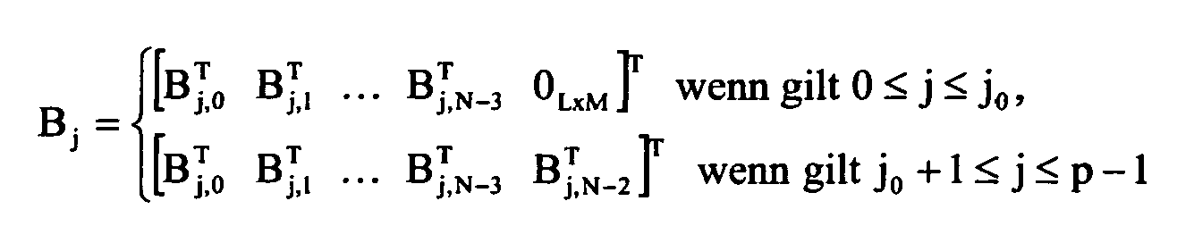
wobei gilt
- Verfahren nach Anspruch 19, dadurch gekennzeichnet, dass es die folgenden Schritte aufweist:- Anwenden eines ersten Vektors X[k], ausgedrückt im Bereich der Teilbänder der Synthesefilterbank, an ein Untersystem, das die transformierte Matrix Bj aufweist, mit j derart, dass gilt j = k mod p,- Summieren der aus der Anwendung der transformierten Matrizen Bj resultierenden Vektoren für jedes j derart, dass gilt 0 ≤ j ≤ p-1,- Erhalt des Vektors Y[n] am Ausgang des globalen Umwandlungssystems durch Addition mit Überlagerung auf die aus der Summierung resultierenden Vektoren,wobei die Schreibweise mod n den Modulo der Zahl n bezeichnet.
- Verfahren nach Anspruch 18, dadurch gekennzeichnet, dass, wenn die zweite Zahl L ein Vielfaches der ersten Zahl M ist, derart, dass gilt L = pM, die Matrizen Aij werden zu

wobei gilt:- 0 ≤ i ≤ p-1, und- Bi die Transformations-Matrizen sind, die ausgedrückt werden durch:
wobei gilt
- Verfahren nach Anspruch 21, dadurch gekennzeichnet, dass es die folgenden Schritte aufweist:- Anwenden eines ersten Vektors X[k], ausgedrückt im Bereich der Teilbänder der Synthesefilterbank, an ein Untersystem, das die Transfermatrix Ai(z) enthält, mit 0 ≤ i ≤ p-1,- für jedes i, das so festgelegt ist, dass gilt 0 ≤ i ≤ p-1, Anwenden einer Transformation einer Matrix Bi an den Vektor X[k], und Addition mit Überlagerung, um einen Ausgangsvektor Yi[n] zu erhalten,- Erhalt eines Ausgangsvektors Y[n] des globalen Umwandlungssystems, der dem Vektor Yi[n] entspricht, mit i derart, dass gilt i = n mod p,wobei die Schreibweise mod n den Modulo der Zahl n bezeichnet.
- Verfahren nach einem der Ansprüche 4 bis 22, bei dem die Filter der Analysebank und der Synthesebank vom Typ mit moduliertem Kosinus und mit endlicher Impulsantwort sind,
dadurch gekennzeichnet, dass die Analyse- und/oder Synthesefilter durch eine Kosinus-Modulation eines Prototyp-Tiefpassfilters H(z) erhalten werden,
so dass die Impulsantworten der Analyse- und/oder Synthesefilter, die jeweils die Vektoren der Transferfunktionen h (z) und/oder f(z) bilden, je für eine Filterbank mit M Bändern ausgedrückt werden durch:
und/oder
wobei gilt: - h[n] die Impulsantwort des Prototyp-Filters der Länge N ist,- n so ist, dass gilt 0 ≤ n ≤ N-1.
 - Verfahren nach den Ansprüchen 4. und 5, dadurch gekennzeichnet, dass, wenn außerdem eine erneute Abtastung um einen rationalen Faktor Q/R zwischen der Synthesefilterbank und der Analysefilterbank durchgeführt wird, die Filtermatrix T̂(z) einer Größe q1M x q2L definiert wird durch:

wobei:- ĝ(z) die Matrix der Größe M x L ist, deren Elemente geliefert werden durch:
0 ≤ n ≤ M-1,
0 ≤ k ≤ L-1,- v̂(z) die Matrix ist, deren Elemente vorzugsweise definiert sind durch: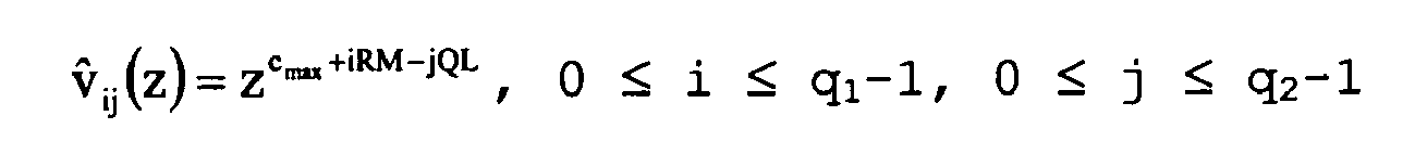
mit cmax = max{n∈N derart, dass gilt h ≤ RM-1 und n durch ggt(L,R) teilbar ist},- und SPB(z) vorzugsweise ein Tiefpassfilter mit einer Grenzfrequenz f̃c = min (π/Q,π/R) und mit einer Verstärkung im Durchlassband Q ist. - Anwendung des Verfahrens nach einem der vorhergehenden Ansprüche an die Transcodierung von einem ersten Typ der Kompressions-Codierung/Decodierung zu mindestens einem zweiten Typ der Kompressions-Codierung/Decodierung, dadurch gekennzeichnet, dass sie darin besteht, in der gleichen Verarbeitung die folgenden Schritte zu komprimieren:- Wiedergewinnen der zumindest teilweise decodierten Daten gemäß dem ersten Typ in Form eines ersten Vektors (X(z)), der eine erste Zahl L von Komponenten in jeweiligen Teilbändern aufweist,- Anwenden des ersten Vektors an eine Synthesefilterbank gemäß dem ersten Typ, dann an eine Analysefilterbank gemäß dem zweiten Typ, und- Wiedergewinnen eines zweiten Vektors (Y(z)), der eine zweite Zahl von Komponenten M in jeweiligen Teilbändern aufweist und an spätere Codierschritte gemäß dem zweiten Typ angewendet werden kann.
- Informatik-Programmprodukt, das dazu bestimmt ist, in einem Speicher einer Ausrüstung eines Kommunikationsnetzwerks wie einem Server, einem Gateway oder auch einem Endgerät gespeichert zu werden,
dadurch gekennzeichnet, dass es Anweisungen zur Durchführung des Verfahrens nach einem der Ansprüche 1 bis 24 aufweist. - Ausrüstung wie ein Server, ein Gateway, oder auch ein Endgerät, die für ein Kommunikationsnetzwerk bestimmt ist, dadurch gekennzeichnet, dass sie Informatik-Ressourcen aufweist, die zur Durchführung des Verfahrens nach einem der Ansprüche 1 bis 24 geeignet sind.
Applications Claiming Priority (2)
| Application Number | Priority Date | Filing Date | Title |
|---|---|---|---|
| FR0409820A FR2875351A1 (fr) | 2004-09-16 | 2004-09-16 | Procede de traitement de donnees par passage entre domaines differents de sous-bandes |
| PCT/FR2005/002127 WO2006032740A1 (fr) | 2004-09-16 | 2005-08-23 | Procede de traitement de donnees par passage entre domaines differents de sous-bandes |
Publications (2)
| Publication Number | Publication Date |
|---|---|
| EP1794748A1 EP1794748A1 (de) | 2007-06-13 |
| EP1794748B1 true EP1794748B1 (de) | 2010-02-17 |
Family
ID=34951876
Family Applications (1)
| Application Number | Title | Priority Date | Filing Date |
|---|---|---|---|
| EP05798240A Ceased EP1794748B1 (de) | 2004-09-16 | 2005-08-23 | Datenverarbeitungsverfahren durch Übergang zwischen verschiedenen Subband-domänen |
Country Status (8)
| Country | Link |
|---|---|
| US (1) | US8639735B2 (de) |
| EP (1) | EP1794748B1 (de) |
| JP (1) | JP4850837B2 (de) |
| CN (1) | CN101069233B (de) |
| AT (1) | ATE458242T1 (de) |
| DE (1) | DE602005019431D1 (de) |
| FR (1) | FR2875351A1 (de) |
| WO (1) | WO2006032740A1 (de) |
Families Citing this family (26)
| Publication number | Priority date | Publication date | Assignee | Title |
|---|---|---|---|---|
| US7422840B2 (en) * | 2004-11-12 | 2008-09-09 | E.I. Du Pont De Nemours And Company | Apparatus and process for forming a printing form having a cylindrical support |
| GB2439685B (en) | 2005-03-24 | 2010-04-28 | Siport Inc | Low power digital media broadcast receiver with time division |
| US7916711B2 (en) * | 2005-03-24 | 2011-03-29 | Siport, Inc. | Systems and methods for saving power in a digital broadcast receiver |
| WO2006138598A2 (en) * | 2005-06-16 | 2006-12-28 | Siport, Inc. | Systems and methods for dynamically controlling a tuner |
| US8335484B1 (en) | 2005-07-29 | 2012-12-18 | Siport, Inc. | Systems and methods for dynamically controlling an analog-to-digital converter |
| US8599841B1 (en) | 2006-03-28 | 2013-12-03 | Nvidia Corporation | Multi-format bitstream decoding engine |
| US8593469B2 (en) * | 2006-03-29 | 2013-11-26 | Nvidia Corporation | Method and circuit for efficient caching of reference video data |
| FR2901433A1 (fr) | 2006-05-19 | 2007-11-23 | France Telecom | Conversion entre representations en domaines de sous-bandes pour des bancs de filtres variant dans le temps |
| US8700387B2 (en) * | 2006-09-14 | 2014-04-15 | Nvidia Corporation | Method and system for efficient transcoding of audio data |
| US8015368B2 (en) * | 2007-04-20 | 2011-09-06 | Siport, Inc. | Processor extensions for accelerating spectral band replication |
| US8199769B2 (en) | 2007-05-25 | 2012-06-12 | Siport, Inc. | Timeslot scheduling in digital audio and hybrid audio radio systems |
| FR2918228A1 (fr) * | 2007-06-29 | 2009-01-02 | France Telecom | Conversion entre domaines de sous-bandes pour bancs de filtres modules. |
| EP2099027A1 (de) * | 2008-03-05 | 2009-09-09 | Deutsche Thomson OHG | Verfahren und Vorrichtung zur Umwandlung zwischen verschiedenen Filterbankdomänen |
| US8335080B2 (en) * | 2009-04-20 | 2012-12-18 | Infortrend Technology, Inc. | Sliding rail having anti-tilting mechanism |
| US8320823B2 (en) * | 2009-05-04 | 2012-11-27 | Siport, Inc. | Digital radio broadcast transmission using a table of contents |
| ES2936307T3 (es) | 2009-10-21 | 2023-03-16 | Dolby Int Ab | Sobremuestreo en un banco de filtros de reemisor combinado |
| US8958510B1 (en) * | 2010-06-10 | 2015-02-17 | Fredric J. Harris | Selectable bandwidth filter |
| BR122021003688B1 (pt) | 2010-08-12 | 2021-08-24 | Fraunhofer-Gesellschaft Zur Forderung Der Angewandten Forschung E. V. | Reamostrar sinais de saída de codecs de áudio com base em qmf |
| US8489053B2 (en) | 2011-01-16 | 2013-07-16 | Siport, Inc. | Compensation of local oscillator phase jitter |
| DE102013212840B4 (de) * | 2013-07-02 | 2022-07-07 | Robert Bosch Gmbh | Modellberechnungseinheit und Steuergerät zur Berechnung eines datenbasierten Funktionsmodells mit Daten in verschiedenen Zahlenformaten |
| CN104656494A (zh) * | 2013-11-19 | 2015-05-27 | 北大方正集团有限公司 | 一种信号实时性处理装置 |
| US9898286B2 (en) * | 2015-05-05 | 2018-02-20 | Intel Corporation | Packed finite impulse response (FIR) filter processors, methods, systems, and instructions |
| EP3182411A1 (de) * | 2015-12-14 | 2017-06-21 | Fraunhofer-Gesellschaft zur Förderung der angewandten Forschung e.V. | Vorrichtung und verfahren zur verarbeitung eines codierten audiosignals |
| EP3206353B1 (de) * | 2016-02-09 | 2020-02-05 | Technische Universität München | Filterbänke und verfahren zum betreiben von filterbänken |
| US20210384892A1 (en) * | 2020-06-09 | 2021-12-09 | The Mathworks, Inc. | Parallel implementations of frame filters with recursive transfer functions |
| CN111968658B (zh) * | 2020-06-30 | 2024-02-06 | 北京百度网讯科技有限公司 | 语音信号的增强方法、装置、电子设备和存储介质 |
Family Cites Families (14)
| Publication number | Priority date | Publication date | Assignee | Title |
|---|---|---|---|---|
| US5508949A (en) * | 1993-12-29 | 1996-04-16 | Hewlett-Packard Company | Fast subband filtering in digital signal coding |
| JP2985675B2 (ja) * | 1994-09-01 | 1999-12-06 | 日本電気株式会社 | 帯域分割適応フィルタによる未知システム同定の方法及び装置 |
| US5610942A (en) * | 1995-03-07 | 1997-03-11 | Chen; Keping | Digital signal transcoder and method of transcoding a digital signal |
| US5950151A (en) * | 1996-02-12 | 1999-09-07 | Lucent Technologies Inc. | Methods for implementing non-uniform filters |
| JP3283200B2 (ja) | 1996-12-19 | 2002-05-20 | ケイディーディーアイ株式会社 | 符号化音声データの符号化レート変換方法および装置 |
| US6947509B1 (en) * | 1999-11-30 | 2005-09-20 | Verance Corporation | Oversampled filter bank for subband processing |
| GB0003954D0 (en) | 2000-02-18 | 2000-04-12 | Radioscape Ltd | Method of and apparatus for converting a signal between data compression formats |
| FR2807897B1 (fr) * | 2000-04-18 | 2003-07-18 | France Telecom | Methode et dispositif d'enrichissement spectral |
| US6963842B2 (en) * | 2001-09-05 | 2005-11-08 | Creative Technology Ltd. | Efficient system and method for converting between different transform-domain signal representations |
| US7020603B2 (en) | 2002-02-07 | 2006-03-28 | Intel Corporation | Audio coding and transcoding using perceptual distortion templates |
| KR100499047B1 (ko) * | 2002-11-25 | 2005-07-04 | 한국전자통신연구원 | 서로 다른 대역폭을 갖는 켈프 방식 코덱들 간의 상호부호화 장치 및 그 방법 |
| US20050018796A1 (en) * | 2003-07-07 | 2005-01-27 | Sande Ravindra Kumar | Method of combining an analysis filter bank following a synthesis filter bank and structure therefor |
| FR2901433A1 (fr) * | 2006-05-19 | 2007-11-23 | France Telecom | Conversion entre representations en domaines de sous-bandes pour des bancs de filtres variant dans le temps |
| EP2099027A1 (de) * | 2008-03-05 | 2009-09-09 | Deutsche Thomson OHG | Verfahren und Vorrichtung zur Umwandlung zwischen verschiedenen Filterbankdomänen |
-
2004
- 2004-09-16 FR FR0409820A patent/FR2875351A1/fr active Pending
-
2005
- 2005-08-23 JP JP2007531786A patent/JP4850837B2/ja not_active Expired - Fee Related
- 2005-08-23 CN CN200580034793.8A patent/CN101069233B/zh not_active Expired - Fee Related
- 2005-08-23 DE DE602005019431T patent/DE602005019431D1/de active Active
- 2005-08-23 US US11/662,980 patent/US8639735B2/en not_active Expired - Fee Related
- 2005-08-23 WO PCT/FR2005/002127 patent/WO2006032740A1/fr active Application Filing
- 2005-08-23 AT AT05798240T patent/ATE458242T1/de not_active IP Right Cessation
- 2005-08-23 EP EP05798240A patent/EP1794748B1/de not_active Ceased
Also Published As
| Publication number | Publication date |
|---|---|
| DE602005019431D1 (de) | 2010-04-01 |
| FR2875351A1 (fr) | 2006-03-17 |
| CN101069233B (zh) | 2011-05-18 |
| US20090198753A1 (en) | 2009-08-06 |
| EP1794748A1 (de) | 2007-06-13 |
| WO2006032740A1 (fr) | 2006-03-30 |
| ATE458242T1 (de) | 2010-03-15 |
| JP4850837B2 (ja) | 2012-01-11 |
| CN101069233A (zh) | 2007-11-07 |
| US8639735B2 (en) | 2014-01-28 |
| JP2008514071A (ja) | 2008-05-01 |
Similar Documents
| Publication | Publication Date | Title |
|---|---|---|
| EP1794748B1 (de) | Datenverarbeitungsverfahren durch Übergang zwischen verschiedenen Subband-domänen | |
| EP1600042B1 (de) | Verfahren zum bearbeiten komprimierter audiodaten zur räumlichen wiedergabe | |
| EP2374123B1 (de) | Verbesserte codierung von mehrkanaligen digitalen audiosignalen | |
| EP2005420B1 (de) | Einrichtung und verfahren zur codierung durch hauptkomponentenanalyse eines mehrkanaligen audiosignals | |
| EP2002424B1 (de) | Vorrichtung und verfahren zur skalierbaren kodierung eines mehrkanaligen audiosignals auf der basis einer hauptkomponentenanalyse | |
| EP2304721B1 (de) | Raumsynthese mehrkanaliger tonsignale | |
| EP2374124B1 (de) | Verwaltete codierung von mehrkanaligen digitalen audiosignalen | |
| CA2512179C (fr) | Procede de codage et de decodage audio a debit variable | |
| CA2766864C (fr) | Codage/decodage perfectionne de signaux audionumeriques | |
| EP2319037B1 (de) | Rekonstruktion von mehrkanal-audiodaten | |
| FR2891098A1 (fr) | Procede et dispositif de mixage de flux audio numerique dans le domaine compresse. | |
| WO2014154988A1 (fr) | Mixage partiel optimisé de flux audio codés selon un codage par sous-bandes | |
| EP2232489A1 (de) | Auf transformation basierende codierung/decodierung mit adaptiven fenstern | |
| WO2007135319A1 (fr) | Conversion entre representations en domaines de sous-bandes pour des bancs de filtres variant dans le temps | |
| WO2023165946A1 (fr) | Codage et décodage optimisé d'un signal audio utilisant un auto-encodeur à base de réseau de neurones | |
| EP2126905B1 (de) | Verfahren und Vorrichtung zur Kodierung und Dekodierung von Audiosignalen, kodiertes Audiosignal | |
| EP1362344A1 (de) | Verfahren und vorrichtung zur rekonstruktion des spektrums von mehrkanaligen signalen | |
| EP2126904A1 (de) | Tonkodierverfahren und vorrichtung | |
| FR2853804A1 (fr) | Procede de decodage d'un signal permettant de reconstituer une scene sonore et dispositif de decodage correspondant | |
| FR2749723A1 (fr) | Procede et dispositif de codage en compression d'un signal numerique |
Legal Events
| Date | Code | Title | Description |
|---|---|---|---|
| PUAI | Public reference made under article 153(3) epc to a published international application that has entered the european phase |
Free format text: ORIGINAL CODE: 0009012 |
|
| 17P | Request for examination filed |
Effective date: 20070316 |
|
| AK | Designated contracting states |
Kind code of ref document: A1 Designated state(s): AT BE BG CH CY CZ DE DK EE ES FI FR GB GR HU IE IS IT LI LT LU LV MC NL PL PT RO SE SI SK TR |
|
| DAX | Request for extension of the european patent (deleted) | ||
| 17Q | First examination report despatched |
Effective date: 20090421 |
|
| GRAP | Despatch of communication of intention to grant a patent |
Free format text: ORIGINAL CODE: EPIDOSNIGR1 |
|
| RTI1 | Title (correction) |
Free format text: DATA PROCESSING METHOD BY PASSAGE BETWEEN DIFFERENT SUB-BAND DOMAINS |
|
| GRAS | Grant fee paid |
Free format text: ORIGINAL CODE: EPIDOSNIGR3 |
|
| GRAA | (expected) grant |
Free format text: ORIGINAL CODE: 0009210 |
|
| AK | Designated contracting states |
Kind code of ref document: B1 Designated state(s): AT BE BG CH CY CZ DE DK EE ES FI FR GB GR HU IE IS IT LI LT LU LV MC NL PL PT RO SE SI SK TR |
|
| REG | Reference to a national code |
Ref country code: GB Ref legal event code: FG4D Free format text: NOT ENGLISH |
|
| REG | Reference to a national code |
Ref country code: CH Ref legal event code: EP |
|
| REG | Reference to a national code |
Ref country code: IE Ref legal event code: FG4D Free format text: LANGUAGE OF EP DOCUMENT: FRENCH |
|
| REF | Corresponds to: |
Ref document number: 602005019431 Country of ref document: DE Date of ref document: 20100401 Kind code of ref document: P |
|
| REG | Reference to a national code |
Ref country code: NL Ref legal event code: VDEP Effective date: 20100217 |
|
| LTIE | Lt: invalidation of european patent or patent extension |
Effective date: 20100217 |
|
| PG25 | Lapsed in a contracting state [announced via postgrant information from national office to epo] |
Ref country code: IS Free format text: LAPSE BECAUSE OF FAILURE TO SUBMIT A TRANSLATION OF THE DESCRIPTION OR TO PAY THE FEE WITHIN THE PRESCRIBED TIME-LIMIT Effective date: 20100617 Ref country code: ES Free format text: LAPSE BECAUSE OF FAILURE TO SUBMIT A TRANSLATION OF THE DESCRIPTION OR TO PAY THE FEE WITHIN THE PRESCRIBED TIME-LIMIT Effective date: 20100528 Ref country code: LT Free format text: LAPSE BECAUSE OF FAILURE TO SUBMIT A TRANSLATION OF THE DESCRIPTION OR TO PAY THE FEE WITHIN THE PRESCRIBED TIME-LIMIT Effective date: 20100217 Ref country code: PT Free format text: LAPSE BECAUSE OF FAILURE TO SUBMIT A TRANSLATION OF THE DESCRIPTION OR TO PAY THE FEE WITHIN THE PRESCRIBED TIME-LIMIT Effective date: 20100617 |
|
| PG25 | Lapsed in a contracting state [announced via postgrant information from national office to epo] |
Ref country code: FI Free format text: LAPSE BECAUSE OF FAILURE TO SUBMIT A TRANSLATION OF THE DESCRIPTION OR TO PAY THE FEE WITHIN THE PRESCRIBED TIME-LIMIT Effective date: 20100217 Ref country code: AT Free format text: LAPSE BECAUSE OF FAILURE TO SUBMIT A TRANSLATION OF THE DESCRIPTION OR TO PAY THE FEE WITHIN THE PRESCRIBED TIME-LIMIT Effective date: 20100217 Ref country code: LV Free format text: LAPSE BECAUSE OF FAILURE TO SUBMIT A TRANSLATION OF THE DESCRIPTION OR TO PAY THE FEE WITHIN THE PRESCRIBED TIME-LIMIT Effective date: 20100217 Ref country code: PL Free format text: LAPSE BECAUSE OF FAILURE TO SUBMIT A TRANSLATION OF THE DESCRIPTION OR TO PAY THE FEE WITHIN THE PRESCRIBED TIME-LIMIT Effective date: 20100217 Ref country code: SI Free format text: LAPSE BECAUSE OF FAILURE TO SUBMIT A TRANSLATION OF THE DESCRIPTION OR TO PAY THE FEE WITHIN THE PRESCRIBED TIME-LIMIT Effective date: 20100217 |
|
| REG | Reference to a national code |
Ref country code: IE Ref legal event code: FD4D |
|
| PG25 | Lapsed in a contracting state [announced via postgrant information from national office to epo] |
Ref country code: EE Free format text: LAPSE BECAUSE OF FAILURE TO SUBMIT A TRANSLATION OF THE DESCRIPTION OR TO PAY THE FEE WITHIN THE PRESCRIBED TIME-LIMIT Effective date: 20100217 Ref country code: CY Free format text: LAPSE BECAUSE OF FAILURE TO SUBMIT A TRANSLATION OF THE DESCRIPTION OR TO PAY THE FEE WITHIN THE PRESCRIBED TIME-LIMIT Effective date: 20100217 Ref country code: NL Free format text: LAPSE BECAUSE OF FAILURE TO SUBMIT A TRANSLATION OF THE DESCRIPTION OR TO PAY THE FEE WITHIN THE PRESCRIBED TIME-LIMIT Effective date: 20100217 Ref country code: IE Free format text: LAPSE BECAUSE OF FAILURE TO SUBMIT A TRANSLATION OF THE DESCRIPTION OR TO PAY THE FEE WITHIN THE PRESCRIBED TIME-LIMIT Effective date: 20100217 Ref country code: GR Free format text: LAPSE BECAUSE OF FAILURE TO SUBMIT A TRANSLATION OF THE DESCRIPTION OR TO PAY THE FEE WITHIN THE PRESCRIBED TIME-LIMIT Effective date: 20100518 Ref country code: SE Free format text: LAPSE BECAUSE OF FAILURE TO SUBMIT A TRANSLATION OF THE DESCRIPTION OR TO PAY THE FEE WITHIN THE PRESCRIBED TIME-LIMIT Effective date: 20100217 Ref country code: RO Free format text: LAPSE BECAUSE OF FAILURE TO SUBMIT A TRANSLATION OF THE DESCRIPTION OR TO PAY THE FEE WITHIN THE PRESCRIBED TIME-LIMIT Effective date: 20100217 |
|
| PG25 | Lapsed in a contracting state [announced via postgrant information from national office to epo] |
Ref country code: SK Free format text: LAPSE BECAUSE OF FAILURE TO SUBMIT A TRANSLATION OF THE DESCRIPTION OR TO PAY THE FEE WITHIN THE PRESCRIBED TIME-LIMIT Effective date: 20100217 Ref country code: CZ Free format text: LAPSE BECAUSE OF FAILURE TO SUBMIT A TRANSLATION OF THE DESCRIPTION OR TO PAY THE FEE WITHIN THE PRESCRIBED TIME-LIMIT Effective date: 20100217 Ref country code: BG Free format text: LAPSE BECAUSE OF FAILURE TO SUBMIT A TRANSLATION OF THE DESCRIPTION OR TO PAY THE FEE WITHIN THE PRESCRIBED TIME-LIMIT Effective date: 20100517 |
|
| PLBE | No opposition filed within time limit |
Free format text: ORIGINAL CODE: 0009261 |
|
| STAA | Information on the status of an ep patent application or granted ep patent |
Free format text: STATUS: NO OPPOSITION FILED WITHIN TIME LIMIT |
|
| 26N | No opposition filed |
Effective date: 20101118 |
|
| PG25 | Lapsed in a contracting state [announced via postgrant information from national office to epo] |
Ref country code: DK Free format text: LAPSE BECAUSE OF FAILURE TO SUBMIT A TRANSLATION OF THE DESCRIPTION OR TO PAY THE FEE WITHIN THE PRESCRIBED TIME-LIMIT Effective date: 20100217 |
|
| BERE | Be: lapsed |
Owner name: FRANCE TELECOM Effective date: 20100831 |
|
| PG25 | Lapsed in a contracting state [announced via postgrant information from national office to epo] |
Ref country code: MC Free format text: LAPSE BECAUSE OF NON-PAYMENT OF DUE FEES Effective date: 20100831 Ref country code: IT Free format text: LAPSE BECAUSE OF FAILURE TO SUBMIT A TRANSLATION OF THE DESCRIPTION OR TO PAY THE FEE WITHIN THE PRESCRIBED TIME-LIMIT Effective date: 20100217 |
|
| REG | Reference to a national code |
Ref country code: CH Ref legal event code: PL |
|
| PG25 | Lapsed in a contracting state [announced via postgrant information from national office to epo] |
Ref country code: CH Free format text: LAPSE BECAUSE OF NON-PAYMENT OF DUE FEES Effective date: 20100831 Ref country code: LI Free format text: LAPSE BECAUSE OF NON-PAYMENT OF DUE FEES Effective date: 20100831 |
|
| PG25 | Lapsed in a contracting state [announced via postgrant information from national office to epo] |
Ref country code: BE Free format text: LAPSE BECAUSE OF NON-PAYMENT OF DUE FEES Effective date: 20100831 |
|
| PG25 | Lapsed in a contracting state [announced via postgrant information from national office to epo] |
Ref country code: HU Free format text: LAPSE BECAUSE OF FAILURE TO SUBMIT A TRANSLATION OF THE DESCRIPTION OR TO PAY THE FEE WITHIN THE PRESCRIBED TIME-LIMIT Effective date: 20100818 Ref country code: LU Free format text: LAPSE BECAUSE OF NON-PAYMENT OF DUE FEES Effective date: 20100823 |
|
| PG25 | Lapsed in a contracting state [announced via postgrant information from national office to epo] |
Ref country code: TR Free format text: LAPSE BECAUSE OF FAILURE TO SUBMIT A TRANSLATION OF THE DESCRIPTION OR TO PAY THE FEE WITHIN THE PRESCRIBED TIME-LIMIT Effective date: 20100217 |
|
| REG | Reference to a national code |
Ref country code: FR Ref legal event code: PLFP Year of fee payment: 11 |
|
| REG | Reference to a national code |
Ref country code: FR Ref legal event code: PLFP Year of fee payment: 12 |
|
| REG | Reference to a national code |
Ref country code: FR Ref legal event code: PLFP Year of fee payment: 13 |
|
| PGFP | Annual fee paid to national office [announced via postgrant information from national office to epo] |
Ref country code: FR Payment date: 20170720 Year of fee payment: 13 Ref country code: GB Payment date: 20170719 Year of fee payment: 13 Ref country code: DE Payment date: 20170719 Year of fee payment: 13 |
|
| REG | Reference to a national code |
Ref country code: DE Ref legal event code: R119 Ref document number: 602005019431 Country of ref document: DE |
|
| GBPC | Gb: european patent ceased through non-payment of renewal fee |
Effective date: 20180823 |
|
| PG25 | Lapsed in a contracting state [announced via postgrant information from national office to epo] |
Ref country code: DE Free format text: LAPSE BECAUSE OF NON-PAYMENT OF DUE FEES Effective date: 20190301 |
|
| PG25 | Lapsed in a contracting state [announced via postgrant information from national office to epo] |
Ref country code: FR Free format text: LAPSE BECAUSE OF NON-PAYMENT OF DUE FEES Effective date: 20180831 |
|
| PG25 | Lapsed in a contracting state [announced via postgrant information from national office to epo] |
Ref country code: GB Free format text: LAPSE BECAUSE OF NON-PAYMENT OF DUE FEES Effective date: 20180823 |