EP1794620B1 - Absolutentfernungsmessvorrichtung zur messung eines bewegten rückstrahlers - Google Patents
Absolutentfernungsmessvorrichtung zur messung eines bewegten rückstrahlers Download PDFInfo
- Publication number
- EP1794620B1 EP1794620B1 EP05804580.8A EP05804580A EP1794620B1 EP 1794620 B1 EP1794620 B1 EP 1794620B1 EP 05804580 A EP05804580 A EP 05804580A EP 1794620 B1 EP1794620 B1 EP 1794620B1
- Authority
- EP
- European Patent Office
- Prior art keywords
- laser
- adm
- retroreflector
- moving
- frequency
- Prior art date
- Legal status (The legal status is an assumption and is not a legal conclusion. Google has not performed a legal analysis and makes no representation as to the accuracy of the status listed.)
- Active
Links
- 238000005259 measurement Methods 0.000 claims description 18
- 238000000034 method Methods 0.000 claims description 13
- 238000010168 coupling process Methods 0.000 description 10
- 238000005859 coupling reaction Methods 0.000 description 10
- 239000011159 matrix material Substances 0.000 description 8
- 230000003287 optical effect Effects 0.000 description 8
- 239000013307 optical fiber Substances 0.000 description 6
- 238000005070 sampling Methods 0.000 description 5
- BWSIKGOGLDNQBZ-LURJTMIESA-N (2s)-2-(methoxymethyl)pyrrolidin-1-amine Chemical compound COC[C@@H]1CCCN1N BWSIKGOGLDNQBZ-LURJTMIESA-N 0.000 description 4
- 239000013078 crystal Substances 0.000 description 4
- 238000010586 diagram Methods 0.000 description 4
- 239000000835 fiber Substances 0.000 description 4
- 230000007246 mechanism Effects 0.000 description 4
- 230000005855 radiation Effects 0.000 description 4
- 230000008878 coupling Effects 0.000 description 3
- 230000008569 process Effects 0.000 description 3
- 230000001133 acceleration Effects 0.000 description 2
- 230000008859 change Effects 0.000 description 2
- 229910052751 metal Inorganic materials 0.000 description 2
- 239000002184 metal Substances 0.000 description 2
- ORILYTVJVMAKLC-UHFFFAOYSA-N Adamantane Natural products C1C(C2)CC3CC1CC2C3 ORILYTVJVMAKLC-UHFFFAOYSA-N 0.000 description 1
- 238000004364 calculation method Methods 0.000 description 1
- 239000002131 composite material Substances 0.000 description 1
- 230000001419 dependent effect Effects 0.000 description 1
- 239000006185 dispersion Substances 0.000 description 1
- 230000005684 electric field Effects 0.000 description 1
- 238000009499 grossing Methods 0.000 description 1
- 238000012986 modification Methods 0.000 description 1
- 230000004048 modification Effects 0.000 description 1
- 229910052701 rubidium Inorganic materials 0.000 description 1
- IGLNJRXAVVLDKE-UHFFFAOYSA-N rubidium atom Chemical compound [Rb] IGLNJRXAVVLDKE-UHFFFAOYSA-N 0.000 description 1
- 230000026676 system process Effects 0.000 description 1
- 230000009897 systematic effect Effects 0.000 description 1
Images


Classifications
-
- G—PHYSICS
- G01—MEASURING; TESTING
- G01B—MEASURING LENGTH, THICKNESS OR SIMILAR LINEAR DIMENSIONS; MEASURING ANGLES; MEASURING AREAS; MEASURING IRREGULARITIES OF SURFACES OR CONTOURS
- G01B11/00—Measuring arrangements characterised by the use of optical techniques
- G01B11/02—Measuring arrangements characterised by the use of optical techniques for measuring length, width or thickness
- G01B11/024—Measuring arrangements characterised by the use of optical techniques for measuring length, width or thickness by means of diode-array scanning
-
- G—PHYSICS
- G01—MEASURING; TESTING
- G01P—MEASURING LINEAR OR ANGULAR SPEED, ACCELERATION, DECELERATION, OR SHOCK; INDICATING PRESENCE, ABSENCE, OR DIRECTION, OF MOVEMENT
- G01P3/00—Measuring linear or angular speed; Measuring differences of linear or angular speeds
- G01P3/36—Devices characterised by the use of optical means, e.g. using infrared, visible, or ultraviolet light
-
- G—PHYSICS
- G01—MEASURING; TESTING
- G01S—RADIO DIRECTION-FINDING; RADIO NAVIGATION; DETERMINING DISTANCE OR VELOCITY BY USE OF RADIO WAVES; LOCATING OR PRESENCE-DETECTING BY USE OF THE REFLECTION OR RERADIATION OF RADIO WAVES; ANALOGOUS ARRANGEMENTS USING OTHER WAVES
- G01S17/00—Systems using the reflection or reradiation of electromagnetic waves other than radio waves, e.g. lidar systems
- G01S17/02—Systems using the reflection of electromagnetic waves other than radio waves
- G01S17/06—Systems determining position data of a target
- G01S17/08—Systems determining position data of a target for measuring distance only
- G01S17/32—Systems determining position data of a target for measuring distance only using transmission of continuous waves, whether amplitude-, frequency-, or phase-modulated, or unmodulated
- G01S17/36—Systems determining position data of a target for measuring distance only using transmission of continuous waves, whether amplitude-, frequency-, or phase-modulated, or unmodulated with phase comparison between the received signal and the contemporaneously transmitted signal
-
- G—PHYSICS
- G01—MEASURING; TESTING
- G01S—RADIO DIRECTION-FINDING; RADIO NAVIGATION; DETERMINING DISTANCE OR VELOCITY BY USE OF RADIO WAVES; LOCATING OR PRESENCE-DETECTING BY USE OF THE REFLECTION OR RERADIATION OF RADIO WAVES; ANALOGOUS ARRANGEMENTS USING OTHER WAVES
- G01S17/00—Systems using the reflection or reradiation of electromagnetic waves other than radio waves, e.g. lidar systems
- G01S17/02—Systems using the reflection of electromagnetic waves other than radio waves
- G01S17/06—Systems determining position data of a target
- G01S17/42—Simultaneous measurement of distance and other co-ordinates
-
- G—PHYSICS
- G01—MEASURING; TESTING
- G01S—RADIO DIRECTION-FINDING; RADIO NAVIGATION; DETERMINING DISTANCE OR VELOCITY BY USE OF RADIO WAVES; LOCATING OR PRESENCE-DETECTING BY USE OF THE REFLECTION OR RERADIATION OF RADIO WAVES; ANALOGOUS ARRANGEMENTS USING OTHER WAVES
- G01S17/00—Systems using the reflection or reradiation of electromagnetic waves other than radio waves, e.g. lidar systems
- G01S17/02—Systems using the reflection of electromagnetic waves other than radio waves
- G01S17/50—Systems of measurement based on relative movement of target
- G01S17/58—Velocity or trajectory determination systems; Sense-of-movement determination systems
-
- G—PHYSICS
- G01—MEASURING; TESTING
- G01S—RADIO DIRECTION-FINDING; RADIO NAVIGATION; DETERMINING DISTANCE OR VELOCITY BY USE OF RADIO WAVES; LOCATING OR PRESENCE-DETECTING BY USE OF THE REFLECTION OR RERADIATION OF RADIO WAVES; ANALOGOUS ARRANGEMENTS USING OTHER WAVES
- G01S17/00—Systems using the reflection or reradiation of electromagnetic waves other than radio waves, e.g. lidar systems
- G01S17/66—Tracking systems using electromagnetic waves other than radio waves
Definitions
- the present disclosure relates to a coordinate measuring device.
- One set of coordinate measurement devices belongs to a class of instruments that measure the coordinates of a point by sending a laser beam to the point.
- the laser beam may impinge directly on the point or may impinge on a retroreflector target that is in contact with the point.
- the instrument determines the coordinates of the point by measuring the distance and the two angles to the target.
- the distance is measured with a distance-measuring device such as an absolute distance meter or an interferometer.
- the angles are measured with an angle-measuring device such as an angular encoder.
- a gimbaled beam-steering mechanism within the instrument directs the laser beam to the point of interest.
- Exemplary systems for determining coordinates of a point are described by U.S. Patent No. 4,790,651 to Brown et al. and U.S. Patent No. 4,714,339 to Lau et al.
- the laser tracker is a particular type of coordinate-measuring device that tracks the retroreflector target with one or more laser beams it emits.
- a device that is closely related to the laser tracker is the laser scanner.
- the laser scanner steps one or more laser beams to points on a diffuse surface.
- the laser tracker and laser scanner are both coordinate-measuring devices. It is common practice today to use the term laser tracker to also refer to laser scanner devices having distance- and angle-measuring capability. This broad definition of laser tracker, which includes laser scanners, is used throughout this application.
- One type of laser tracker contains only an interferometer without an absolute distance meter. If an object blocks the path of the laser beam from one of these trackers, the interferometer loses its distance reference. The operator must then track the retroreflector to a known location before continuing the measurement.
- a way around this limitation is to put an absolute distance meter (ADM) in the tracker.
- the ADM can measure distance in a point-and-shoot manner.
- Some laser trackers contain only an ADM without an interferometer.
- An exemplary laser tracker of this type is described in U.S. Patent Number 5,455,670 to Payne, et al.
- Other laser trackers typically contain both an ADM and an interferometer.
- An exemplary laser tracker of this type is described in U.S. Patent Number 5,764,360 to Meier, et al.
- One of the main applications for laser trackers is to scan the surface features of objects to determine their geometrical characteristics. For example, an operator can determine the angle between two surfaces by scanning each of the surfaces and then fitting a geometrical plane to each. As another example, an operator can determine the center and radius of a sphere by scanning the sphere surface.
- an interferometer rather than an ADM, has been required for the laser tracker to scan. The reason for this is that absolute distance measurements have only been possible on stationary targets. Consequently, to get full functionality with both scanning and point-and-shoot capability, laser trackers have required both an interferometer and an ADM. What is needed is an ADM that has the ability to accurately and quickly scan a moving target. This permits tracker cost to be reduced because the interferometer is no longer needed.
- WO 03/062744 discloses a laser based method for measuring coordinates of a remote retroreflective target, comprising the steps of:
- a laser device and method capable of one or more dimensional absolute distance measurements and/or surface scanning and/or coordinate measurements of a moving external retroreflector or other moving target surfaces without using an incremental interferometer depending upon what the application requires.
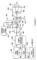
- FIGURE 1 is a perspective view of an exemplary laser tracker sending a laser beam to an external retroreflector
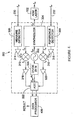
- FIGURE 2 is a block diagram of some of the main elements within the exemplary laser tracker of FIGURE 1 ;
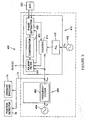
- FIGURE 3 is a block diagram of the elements within the exemplary fiber-coupling network of FIGURE 2 ;
- FIGURE 4 is a block diagram of the elements within the exemplary ADM electronics of FIGURE 2 ;
- FIGURE 5 is a block diagram of the elements within an exemplary ADM data-processing system for computing the distance to a moving retroreflector.
- An exemplary laser tracker 10 is illustrated in FIGURE 1 .
- An exemplary gimbaled beam-steering mechanism 12 of the laser tracker comprises zenith carriage 14 that is mounted on azimuth base 16.
- the zenith and azimuth mechanical axes internal to the tracker are turned to point the laser beam 46 in the desired direction.
- the laser beam may comprise one or more laser wavelengths, as will be described in the discussion that follows.
- the zenith and azimuth angular encoders internal to the tracker (not shown) are attached to the zenith and azimuth mechanical axes and indicate, to high accuracy, the angles of rotation.
- this sort of gimbal mechanism 12 is assumed in the following discussion. However, other types of gimbal mechanisms are possible, and the techniques described here are also applicable to these other types.
- Laser beam 46 travels to external retroreflector 26.
- the most common type of retroreflector is a spherically mounted retroreflector (SMR), which comprises a metal sphere into which a cube-corner retroreflector (not shown) is embedded.
- the cube-corner retroreflector comprises three perpendicular mirrors that come together at a common apex point. The apex point is placed at the center of the metal sphere.
- SMR spherically mounted retroreflector
- a retrosphere or any other device that sends the return laser beam back on itself may be used as the external retroreflector 26.
- ADM electronics 300 modulates the optical power of ADM laser 102, which sends light through fiber-optic cable 104 and fiber-coupling network 200. Some of the light from the fiver-coupling network 200 travels to ADM beam launch 140. Another part of the light travels through fiber loop 106 and then back into fiber-coupling network 200.
- ADM beam launch 140 comprises stable ferrule 142 and positive lens 144. Collimated light 108 emerges from the fiber launch 140.
- Visible-light laser 110 sends visible light into beam launch 150, which comprises stable ferrule 152 and positive lens 154.
- the visible laser beam 112 that emerges to the beam launch 150 is collimated.
- Dichroic beam splitter 114 transmits ADM beam 108 but reflects visible beam 112.
- composite laser beam 116 comprises the visible laser beam and ADM laser beam, which are substantially collinear.
- Laser beam 116 passes through beam splitter 118 and beam expander 160, emerging as a larger collimated laser beam 46.
- the beam expander comprises negative lens 162 and positive lens 164.
- the laser beam 46 travels to external retroreflector 26, as shown in FIGURE 1 .
- the beam reflects off retroreflector 26 and returns to the laser tracker. If the laser beam strikes the center of the retroreflector, the reflected laser beam retraces the path of the incident laser beam. If the laser beam strikes the retroreflector off the center, the reflected laser beam returns parallel to the incident beam but offset from it. The returning laser beam re-enters the tracker and retraces the path back through the optical system. Some of the returning laser light reflects off beam splitter 118. Reflected laser light 126 passes through optical filter 128 and strikes position detector 130. The optical filter 128 blocks either the ADM light or the visible light in the beam 126.
- the position detector 130 responds to the light that passes through the optical filter 128 by indicating the position of the laser beam on its surface.
- the retrace point of the position detector is defined as the point that the laser beam 126 strikes if the beam 46 strikes the center of retroreflector 26.
- the laser beam 126 moves off the retrace point and causes the position detector 130 to generate an electrical error signal.
- a servo system processes this error signal to activate motors that turn the laser tracker toward the center of the external retroreflector 26.
- the dichroic beam splitter 114 reflects the returning visible laser beam but transmits the returning ADM laser beam.
- the returning ADM laser beam travels through the beam launch and is coupled into the optical fiber within the stable ferrule 142. This light travels through the fiber-coupling network 200 and emerges from optical fiber 230. That portion of the laser light that traveled through fiber loop 106 emerges from optical fiber 232.
- Both fibers 230 and 232 continue into the ADM electronics section 300, where their modulated powers are converted into electrical signals. These signals are processed by the ADM electronics to provide the result, which is the distance from the tracker to the retroreflector target.
- Exemplary fiber-coupling network 200 of FIGURE 3 comprises first fiber-optic coupler 204, second fiber-optic coupler 206, and low-reflection terminations 208 and 210.
- Light from ADM laser 102 travels through fiber-optic cable 104 and enters first fiber-optic coupler 204.
- Fiber-optic coupler 204 sends 10% of the laser light through fiber-loop 106 and into optical fiber 232, which travels to ADM electronics 300.
- Fiber-optic coupler 204 sends the other 90% of the laser light through fiber-optic coupler 206, which sends half of the laser light to low-reflection termination 208 and the other half of the laser light to stable ferrule 142.
- ADAM electronics 300 of FIGURE 4 comprises frequency reference 302, synthesizer 304, measure detector 306, reference detector 308, mixers 310, 312, amplifiers 314, 316, 318, 320, frequency divider 324, and analog-to-digital converter (ADC) 322.
- Frequency reference 302 provides the time base for the ADM and should have low phase noise and low frequency drift.
- the frequency reference may be an oven-controlled crystal oscillator (OCXO), rubidium oscillator, or any other highly stable frequency reference.
- OXO oven-controlled crystal oscillator
- rubidium oscillator or any other highly stable frequency reference.
- the oscillator frequency should be accurate and stable to within a small fraction of a part per million.
- the signal from the frequency reference is put into the synthesizer, which generates three signals.
- the first signal is at frequency f RF and modulates the optical power of ADM laser 102.
- This type of modulation is called intensity modulation (IM).
- IM intensity modulation
- AM amplitude modulation
- the second and third signals, both at the frequency f LO go to the local-oscillator ports of mixers 310 and 312.
- Fiber-optic cables 230 and 232 carry laser light.
- the light in these fiber-optic cables is converted into electrical signals by measure detector 306 and reference detector 308.
- These optical detectors send the modulation frequency f RF to amplifiers 314, 316 and then to mixers 310, 312.
- Each mixer produces two frequencies, one at
- These signals travel to low-frequency amplifiers 318, 320.
- ADC analog-to-digital converter
- the frequency reference 302 sends a signal into frequency divider 324, which divides the frequency of the reference 302 by an integer N to produce a sampling clock.
- the ADC may decimate the sampled signals by an integer factor M , so that the effective sampling rate is f REF / NM. This effective sampling rate should be an integer multiple of the intermediate frequency f IF .
- the ADC sends the sampled data for the measure and reference channels to data processors 400 for analysis.
- Data processors include digital signal processor (DSP) chips and general-purpose microprocessor chips. The processing performed by these processors is described below.
- Data processor 400 of FIGURE 5 takes the digitized data from ADC 322 and derives from it the distance from the tracker to external retroreflector 26.
- FIGURE 5 refers to this distance as the RESULT.
- Data processor 400 comprises digital signal processor 410, microprocessor 450, and crystal oscillators 402, 404.
- Analog-to-digital converter 322 sends sampled data to DSP 410. This data is routed to a program that runs within the DSP. This program contains three main functions: phase-extractor function 420, compensator function 422, and Kalman-filter function 424.
- the purpose of the phase-extractor function is to determine the phases of the signals in the reference and measure channels, that is, the phases of the signals that pass through the measure detector 306 and reference detector 308. To determine these phases, the modulation range must first be calculated. Modulation range is defined as the round-trip distance traveled by the ADM laser light in air for the phase of the laser modulation to change by 2 pi radians.
- the modulation range is approximately 52 millimeters.
- f REF 20 MHz
- N 10
- M 8
- f IF 10 kHz.
- the phase-extractor function 420 is dependent on the speed or velocity v, for example the radial speed, of the target as show in equation (2), (3), (5), and (6).
- the quantity W is an integer that accounts for the number of whole modulation intervals to the target. The method for finding this integer is discussed below. In some systems, there may be additional systematic errors that can be removed by appending additional terms to equation (8).
- the compensator 422 sends the distance values to Kalman filter 424.
- the Kalman filter is a numerical algorithm applied to the distance data to give the best estimate of distance and speed of external retroreflector 26 as a function of time and in the presence of noise.
- the ADM distance data is collected at high speed and has some level of random noise in the distance readings. This small error is greatly amplified in calculating speed, since small differences in distance are divided by a small increment in time.
- the Kalman filter can be thought of as an intelligent smoothing function that optimizes accuracy based on the noise of the system and the speed of the target.
- the Kalman filter also serves to synchronize the ADM readings with the readings of the angular encoders and the position detector.
- the angular encoders and position detector latch their readings whenever they receive the sync pulse, which occurs at frequency f SYNC .
- the frequency of the sync pulse is in general different than the frequency of calculation of the ADM.
- the Kalman filter provides synchronization of the ADM with the angular encoders and position detector by extrapolating the position forward in time to the next sync pulse.
- the subscript m represents an a priori estimate and the subscript p represents an a posteriori estimate.
- the matrix Q is the process noise covariance.
- the acceleration is not explicitly calculated. Instead the acceleration is assumed to have a dispersion characterized by the variance ⁇ A 2 .
- the process-noise variance ⁇ A 2 is selected so as to minimize the error in the position of a moving target.
- P m is the state covariance matrix at the present point in time. It is found from the state covariance matrix at the last point in time and the process noise covariance.
- the state covariance matrix and the measurement noise covariance R are used to determine the filter gain K.
- the measurement noise covariance is just the variance ⁇ M 2 in readings caused by noise in the measurement device.
- the measurement noise in the ADM system is determined by simply calculating the variance ⁇ ADM 2 in the distances reported while the ADM is measuring a stationary target.
- Equation (12) is interpreted as follows.
- x m is the initial guess for the state vector (distance and radial speed) based on the distance and radial speed for the previous point in time.
- the quantity z is the measured distance d and Hx m is the estimated distance.
- the quantity z - Hx m is the difference between the measured and estimated distances. This difference is multiplied by the gain matrix K to provide an adjustment to the initial estimate x m for the state matrix.
- the best estimate for the distance is a value between the measured distance and the estimated distance.
- Equation (12) provides a mathematically sound method of selecting the best ( a posteriori ) estimate of the distance and radial speed.
- Equation (13) provides a new estimate for the state covariance P p at the next point in time. Equations (9) - (13) are solved each time compensator function 422 sends a new measured value to the Kalman filter.
- counter 414 determines the difference in time between the sync pulse and the last state distance. It does this in the following way.
- Crystal oscillator 404 sends a low-frequency sine wave to frequency divider 452, located within microprocessor 450. This clock frequency is divided down to f SYNC , the frequency of the sync pulse.
- the sync pulse is sent over device bus 72 to DSP 410, angular encoder electronics 74, and position-detector electronics 76.
- the sync pulse is sent to counter 414, which resides within DSP 410.
- the counter is clocked by crystal 402, which drives a phase-locked loop (PLL) device 412 within the DSP.
- PLL phase-locked loop
- oscillator 402 has a frequency of 30 MHz and PLL 412 doubles this to produce a clock signal of 60 MHz to counter 414.
- the phase-extractor function 420 sends a signal to the counter when the ADC 322 has sent all the samples for one cycle. This resets counter 414 and begins a new count.
- the sync pulse stops the counting of counter 412. The total number of counts is divided by the frequency to determine the elapsed time. Since the time interval in the above equations was set to one, the normalized time interval t NORM is the elapsed time divided by the time interval.
- the Kalman-filter function 424 provides the result, which is the distance from the tracker to external retroreflector 26.
- the Kalman filter also provides the velocity to phase-extractor function 420 to apply in equations (2), (3), (5), and (6).
- the quantity W was introduced in equation (8) as an integer that accounts for the number of whole modulation intervals to the target.
- This integer value W is found by first measuring the distance to the external retroreflector 26. The frequencies f RF and f LO are changed by a fixed amount and the distances are again measured. If the RF frequencies before and after the change are f 1 and f 2 and the phase difference between the two measurements is p then the integer W is equal to the integer portion of ( p /2 ⁇ )( f 1 /
- f 1 and f 2 differ by 2.5 MHz, and if the f 1 is 2800 MHz, then the technique will work out to about 60 meters.
- a third frequency can be added to assist in determining the value of the integer W . Once W has been determined, it is not necessary to switch the frequencies again unless the beam is broken. If the ADM continues to measure the external retroreflector 26 without interruption, then it can easily keep track of the changes in the integer W .
Claims (1)
- Verfahren, das zu einer dimensionalen absoluten Abstandsmessung eines sich bewegenden externen Retroreflektors (26) oder anderer sich bewegender Zielflächen in der Lage ist, umfassend:Bereitstellung einer Laserlicht-Quelle (102), die Amplituden- oder Intensitäts-moduliert ist und an den und von dem sich bewegenen externen Retroreflektor oder anderen sich bewegenden Flächen an die Laservorrichtung entlang einem Messpfad zurückgeschickt wird;Umwandlung des Laserlichts, das von einem Retroreflektor oder von Zielflächen entlang dem Messweg zurückgeschickt wird, in ein elektrisches Signal;Digitalisierung der Werte des elektrischen Signals;Empfang der digitalisierten Werte des elektrischen Signals;Durchführung einer Kalman-Filterfunktion (424), die konfiguriert ist, um eine Geschwindigkeit v der Bewegung des externen Retroreflektors oder der anderen sich bewegenden Zielfläche zu schätzen;Durchführung einer Geschwindigkeits-abhängigen Phasenextraktionsfunktion (420) auf den digitalisierten Werten und auf der Geschwindigkeit v von der Kalman-Filterfunktion (424); undBerechnung eines absoluten Abstands d zu dem sich bewegenden Retroreflektor oder anderen Ziel, das sich mit der Geschwindigkeit v bewegt.
Applications Claiming Priority (2)
| Application Number | Priority Date | Filing Date | Title |
|---|---|---|---|
| US61477804P | 2004-09-30 | 2004-09-30 | |
| PCT/US2005/035578 WO2006039682A1 (en) | 2004-09-30 | 2005-09-30 | Absolute distance meter that measures a moving retroreflector |
Publications (2)
| Publication Number | Publication Date |
|---|---|
| EP1794620A1 EP1794620A1 (de) | 2007-06-13 |
| EP1794620B1 true EP1794620B1 (de) | 2014-01-01 |
Family
ID=35517446
Family Applications (1)
| Application Number | Title | Priority Date | Filing Date |
|---|---|---|---|
| EP05804580.8A Active EP1794620B1 (de) | 2004-09-30 | 2005-09-30 | Absolutentfernungsmessvorrichtung zur messung eines bewegten rückstrahlers |
Country Status (5)
| Country | Link |
|---|---|
| US (2) | US7352446B2 (de) |
| EP (1) | EP1794620B1 (de) |
| JP (1) | JP5235412B2 (de) |
| CN (1) | CN101031817B (de) |
| WO (1) | WO2006039682A1 (de) |
Families Citing this family (132)
| Publication number | Priority date | Publication date | Assignee | Title |
|---|---|---|---|---|
| US7583375B2 (en) * | 2003-09-05 | 2009-09-01 | Faro Technologies, Inc. | Self-compensating laser tracker |
| JP2007504459A (ja) * | 2003-09-05 | 2007-03-01 | ファロ テクノロジーズ インコーポレーテッド | 自己補償レーザトラッカ |
| DE202006005643U1 (de) * | 2006-03-31 | 2006-07-06 | Faro Technologies Inc., Lake Mary | Vorrichtung zum dreidimensionalen Erfassen eines Raumbereichs |
| JP2007309677A (ja) * | 2006-05-16 | 2007-11-29 | Mitsutoyo Corp | 追尾式レーザ干渉計の絶対距離推定方法及び追尾式レーザ干渉計 |
| DE102006031580A1 (de) | 2006-07-03 | 2008-01-17 | Faro Technologies, Inc., Lake Mary | Verfahren und Vorrichtung zum dreidimensionalen Erfassen eines Raumbereichs |
| WO2008121919A1 (en) * | 2007-03-30 | 2008-10-09 | Faro Technologies, Inc. | Absolute distance meter |
| GB0706821D0 (en) * | 2007-04-10 | 2007-05-16 | Renishaw Plc | Rotation detection kit |
| DE102007061384A1 (de) | 2007-12-19 | 2009-06-25 | Robert Bosch Gmbh | Entfernungsmessvorrichtung sowie System |
| US8509949B2 (en) * | 2008-03-21 | 2013-08-13 | Variation Reduction Solutions, Inc. | External system for robotic accuracy enhancement |
| US7908757B2 (en) | 2008-10-16 | 2011-03-22 | Hexagon Metrology, Inc. | Articulating measuring arm with laser scanner |
| DE112009003495T5 (de) | 2008-11-17 | 2013-01-10 | Faro Technologies, Inc. | Vorrichtung und Verfahren zum Messen von sechs Freiheitsgraden |
| WO2012141810A1 (en) | 2011-03-03 | 2012-10-18 | Faro Technologies, Inc. | Target apparatus and method |
| US9482755B2 (en) | 2008-11-17 | 2016-11-01 | Faro Technologies, Inc. | Measurement system having air temperature compensation between a target and a laser tracker |
| US7895015B2 (en) * | 2008-12-04 | 2011-02-22 | Parker David H | Method for measuring the structural health of a civil structure |
| US10203268B2 (en) | 2008-12-04 | 2019-02-12 | Laura P. Solliday | Methods for measuring and modeling the process of prestressing concrete during tensioning/detensioning based on electronic distance measurements |
| US9354043B2 (en) | 2008-12-04 | 2016-05-31 | Laura P. Solliday | Methods for measuring and modeling the structural health of pressure vessels based on electronic distance measurements |
| US7856334B2 (en) * | 2008-12-06 | 2010-12-21 | Parker David H | Method for calibrating a laser-based spherical coordinate measurement system by a mechanical harmonic oscillator |
| DE102009010465B3 (de) * | 2009-02-13 | 2010-05-27 | Faro Technologies, Inc., Lake Mary | Laserscanner |
| US9551575B2 (en) | 2009-03-25 | 2017-01-24 | Faro Technologies, Inc. | Laser scanner having a multi-color light source and real-time color receiver |
| DE102009015920B4 (de) | 2009-03-25 | 2014-11-20 | Faro Technologies, Inc. | Vorrichtung zum optischen Abtasten und Vermessen einer Umgebung |
| US8082673B2 (en) * | 2009-11-06 | 2011-12-27 | Hexagon Metrology Ab | Systems and methods for control and calibration of a CMM |
| DE102009035336B3 (de) | 2009-07-22 | 2010-11-18 | Faro Technologies, Inc., Lake Mary | Vorrichtung zum optischen Abtasten und Vermessen einer Umgebung |
| DE102009035337A1 (de) | 2009-07-22 | 2011-01-27 | Faro Technologies, Inc., Lake Mary | Verfahren zum optischen Abtasten und Vermessen eines Objekts |
| US8659749B2 (en) * | 2009-08-07 | 2014-02-25 | Faro Technologies, Inc. | Absolute distance meter with optical switch |
| US20110069322A1 (en) * | 2009-09-21 | 2011-03-24 | Faro Technologies, Inc. | Laser pointing mechanism |
| US9529083B2 (en) | 2009-11-20 | 2016-12-27 | Faro Technologies, Inc. | Three-dimensional scanner with enhanced spectroscopic energy detector |
| US9210288B2 (en) | 2009-11-20 | 2015-12-08 | Faro Technologies, Inc. | Three-dimensional scanner with dichroic beam splitters to capture a variety of signals |
| US9113023B2 (en) | 2009-11-20 | 2015-08-18 | Faro Technologies, Inc. | Three-dimensional scanner with spectroscopic energy detector |
| DE102009055989B4 (de) | 2009-11-20 | 2017-02-16 | Faro Technologies, Inc. | Vorrichtung zum optischen Abtasten und Vermessen einer Umgebung |
| DE102009055988B3 (de) | 2009-11-20 | 2011-03-17 | Faro Technologies, Inc., Lake Mary | Vorrichtung zum optischen Abtasten und Vermessen einer Umgebung |
| DE102009057101A1 (de) | 2009-11-20 | 2011-05-26 | Faro Technologies, Inc., Lake Mary | Vorrichtung zum optischen Abtasten und Vermessen einer Umgebung |
| US8630314B2 (en) | 2010-01-11 | 2014-01-14 | Faro Technologies, Inc. | Method and apparatus for synchronizing measurements taken by multiple metrology devices |
| US8773667B2 (en) * | 2010-01-18 | 2014-07-08 | Faro Technologies, Inc. | Sphere bar probe |
| US8677643B2 (en) | 2010-01-20 | 2014-03-25 | Faro Technologies, Inc. | Coordinate measurement machines with removable accessories |
| US8615893B2 (en) | 2010-01-20 | 2013-12-31 | Faro Technologies, Inc. | Portable articulated arm coordinate measuring machine having integrated software controls |
| US9628775B2 (en) | 2010-01-20 | 2017-04-18 | Faro Technologies, Inc. | Articulated arm coordinate measurement machine having a 2D camera and method of obtaining 3D representations |
| GB2490452A (en) | 2010-01-20 | 2012-10-31 | Faro Tech Inc | Integrated part temperature measurement system |
| US9607239B2 (en) | 2010-01-20 | 2017-03-28 | Faro Technologies, Inc. | Articulated arm coordinate measurement machine having a 2D camera and method of obtaining 3D representations |
| US8898919B2 (en) | 2010-01-20 | 2014-12-02 | Faro Technologies, Inc. | Coordinate measurement machine with distance meter used to establish frame of reference |
| JP5306545B2 (ja) | 2010-01-20 | 2013-10-02 | ファロ テクノロジーズ インコーポレーテッド | 照明付きプローブ端を有する座標測定機および動作方法 |
| US9879976B2 (en) | 2010-01-20 | 2018-01-30 | Faro Technologies, Inc. | Articulated arm coordinate measurement machine that uses a 2D camera to determine 3D coordinates of smoothly continuous edge features |
| US8832954B2 (en) | 2010-01-20 | 2014-09-16 | Faro Technologies, Inc. | Coordinate measurement machines with removable accessories |
| US9163922B2 (en) | 2010-01-20 | 2015-10-20 | Faro Technologies, Inc. | Coordinate measurement machine with distance meter and camera to determine dimensions within camera images |
| US8875409B2 (en) | 2010-01-20 | 2014-11-04 | Faro Technologies, Inc. | Coordinate measurement machines with removable accessories |
| CN102947667A (zh) | 2010-01-20 | 2013-02-27 | 法罗技术股份有限公司 | 具有可移除的附件装置的坐标测量机 |
| US8422034B2 (en) | 2010-04-21 | 2013-04-16 | Faro Technologies, Inc. | Method and apparatus for using gestures to control a laser tracker |
| US9377885B2 (en) | 2010-04-21 | 2016-06-28 | Faro Technologies, Inc. | Method and apparatus for locking onto a retroreflector with a laser tracker |
| US8537371B2 (en) | 2010-04-21 | 2013-09-17 | Faro Technologies, Inc. | Method and apparatus for using gestures to control a laser tracker |
| US9400170B2 (en) | 2010-04-21 | 2016-07-26 | Faro Technologies, Inc. | Automatic measurement of dimensional data within an acceptance region by a laser tracker |
| US9772394B2 (en) | 2010-04-21 | 2017-09-26 | Faro Technologies, Inc. | Method and apparatus for following an operator and locking onto a retroreflector with a laser tracker |
| US8619265B2 (en) | 2011-03-14 | 2013-12-31 | Faro Technologies, Inc. | Automatic measurement of dimensional data with a laser tracker |
| US8724119B2 (en) | 2010-04-21 | 2014-05-13 | Faro Technologies, Inc. | Method for using a handheld appliance to select, lock onto, and track a retroreflector with a laser tracker |
| DE102010020925B4 (de) | 2010-05-10 | 2014-02-27 | Faro Technologies, Inc. | Verfahren zum optischen Abtasten und Vermessen einer Umgebung |
| DE102010032723B3 (de) | 2010-07-26 | 2011-11-24 | Faro Technologies, Inc. | Vorrichtung zum optischen Abtasten und Vermessen einer Umgebung |
| DE102010032726B3 (de) | 2010-07-26 | 2011-11-24 | Faro Technologies, Inc. | Vorrichtung zum optischen Abtasten und Vermessen einer Umgebung |
| DE102010032725B4 (de) | 2010-07-26 | 2012-04-26 | Faro Technologies, Inc. | Vorrichtung zum optischen Abtasten und Vermessen einer Umgebung |
| DE102010033561B3 (de) | 2010-07-29 | 2011-12-15 | Faro Technologies, Inc. | Vorrichtung zum optischen Abtasten und Vermessen einer Umgebung |
| GB2501390B (en) | 2010-09-08 | 2014-08-06 | Faro Tech Inc | A laser scanner or laser tracker having a projector |
| US9168654B2 (en) | 2010-11-16 | 2015-10-27 | Faro Technologies, Inc. | Coordinate measuring machines with dual layer arm |
| US8902408B2 (en) | 2011-02-14 | 2014-12-02 | Faro Technologies Inc. | Laser tracker used with six degree-of-freedom probe having separable spherical retroreflector |
| US9164173B2 (en) | 2011-04-15 | 2015-10-20 | Faro Technologies, Inc. | Laser tracker that uses a fiber-optic coupler and an achromatic launch to align and collimate two wavelengths of light |
| USD688577S1 (en) | 2012-02-21 | 2013-08-27 | Faro Technologies, Inc. | Laser tracker |
| US9482529B2 (en) | 2011-04-15 | 2016-11-01 | Faro Technologies, Inc. | Three-dimensional coordinate scanner and method of operation |
| JP2014516409A (ja) | 2011-04-15 | 2014-07-10 | ファロ テクノロジーズ インコーポレーテッド | レーザトラッカの改良位置検出器 |
| US9686532B2 (en) | 2011-04-15 | 2017-06-20 | Faro Technologies, Inc. | System and method of acquiring three-dimensional coordinates using multiple coordinate measurement devices |
| WO2013028649A1 (en) * | 2011-08-23 | 2013-02-28 | Bae Systems Information And Electronic Systems Integration Inc. | Fiber optically coupled laser rangefinder for use in a gimbal system |
| US9222771B2 (en) | 2011-10-17 | 2015-12-29 | Kla-Tencor Corp. | Acquisition of information for a construction site |
| US9008999B2 (en) * | 2011-10-27 | 2015-04-14 | Toyota Motor Engineering & Manufacturing North America, Inc. | Steering wheel airbag position detector |
| US9822956B2 (en) * | 2012-01-05 | 2017-11-21 | Cast Group Of Companies Inc. | System and method for calibrating a fixture configured to rotate and/or translate |
| DE102012100609A1 (de) | 2012-01-25 | 2013-07-25 | Faro Technologies, Inc. | Vorrichtung zum optischen Abtasten und Vermessen einer Umgebung |
| JP6099675B2 (ja) | 2012-01-27 | 2017-03-22 | ファロ テクノロジーズ インコーポレーテッド | バーコード識別による検査方法 |
| GB2513806B (en) | 2012-01-30 | 2016-07-20 | Faro Tech Inc | Laser tracker used with six degree-of-freedom probe having separable spherical retroreflector |
| GB201205563D0 (en) * | 2012-03-29 | 2012-05-09 | Sec Dep For Business Innovation & Skills The | Coordinate measurement system and method |
| EP2831625B1 (de) | 2012-03-29 | 2021-02-17 | NPL Management Limited | Messvorrichtung, system und verfahren |
| US9482525B2 (en) | 2012-05-16 | 2016-11-01 | Faro Technologies, Inc. | Apparatus to compensate bearing runout in a three-dimensional coordinate measuring system |
| WO2013173116A1 (en) | 2012-05-16 | 2013-11-21 | Faro Technologies, Inc. | An apparatus and method to compensate bearing runout in laser tracker |
| US9746304B2 (en) | 2012-05-16 | 2017-08-29 | Faro Technologies, Inc. | Apparatus and method to compensate bearing runout in an articulated arm coordinate measurement machine |
| US9488476B2 (en) | 2014-02-06 | 2016-11-08 | Faro Technologies, Inc. | Apparatus and method to compensate bearing runout in an articulated arm coordinate measurement machine |
| US9423282B2 (en) | 2014-06-12 | 2016-08-23 | Faro Technologies, Inc. | Metrology device and a method for compensating for bearing runout error |
| WO2013188025A1 (en) | 2012-06-15 | 2013-12-19 | Faro Technologies, Inc. | Coordinate measurement machines with removable accessories |
| US8997362B2 (en) | 2012-07-17 | 2015-04-07 | Faro Technologies, Inc. | Portable articulated arm coordinate measuring machine with optical communications bus |
| DE102012107544B3 (de) | 2012-08-17 | 2013-05-23 | Faro Technologies, Inc. | Vorrichtung zum optischen Abtasten und Vermessen einer Umgebung |
| DE102012109481A1 (de) | 2012-10-05 | 2014-04-10 | Faro Technologies, Inc. | Vorrichtung zum optischen Abtasten und Vermessen einer Umgebung |
| US9513107B2 (en) | 2012-10-05 | 2016-12-06 | Faro Technologies, Inc. | Registration calculation between three-dimensional (3D) scans based on two-dimensional (2D) scan data from a 3D scanner |
| US10067231B2 (en) | 2012-10-05 | 2018-09-04 | Faro Technologies, Inc. | Registration calculation of three-dimensional scanner data performed between scans based on measurements by two-dimensional scanner |
| EP2770339B1 (de) * | 2013-02-26 | 2019-11-27 | Hexagon Technology Center GmbH | Sensorsynchronisationsverfahren und ebensolches Sensormesssystem |
| US9041914B2 (en) | 2013-03-15 | 2015-05-26 | Faro Technologies, Inc. | Three-dimensional coordinate scanner and method of operation |
| EP2789972B1 (de) * | 2013-04-12 | 2017-08-16 | Hexagon Technology Center GmbH | Vermessungsgerät mit verformbarem optischem Element |
| US9234742B2 (en) | 2013-05-01 | 2016-01-12 | Faro Technologies, Inc. | Method and apparatus for using gestures to control a laser tracker |
| US9772173B2 (en) | 2013-06-27 | 2017-09-26 | Faro Technologies, Inc. | Method for measuring 3D coordinates of a surface with a portable articulated arm coordinate measuring machine having a camera |
| US9476695B2 (en) * | 2013-07-03 | 2016-10-25 | Faro Technologies, Inc. | Laser tracker that cooperates with a remote camera bar and coordinate measurement device |
| GB201313751D0 (en) | 2013-08-01 | 2013-09-18 | Renishaw Plc | Rotation Detection Apparatus |
| CN103591891B (zh) * | 2013-11-20 | 2015-04-29 | 天津大学 | 室内空间测量定位系统的精密控制场精度溯源方法 |
| US9121689B2 (en) * | 2013-12-11 | 2015-09-01 | Faro Technologies, Inc. | Method for correcting a spherically mounted retroreflector when resetting a distance meter |
| US9239238B2 (en) | 2013-12-11 | 2016-01-19 | Faro Technologies, Inc. | Method for correcting a 3D measurement of a spherically mounted retroreflector on a nest |
| US9347767B2 (en) | 2013-12-11 | 2016-05-24 | Faro Technologies, Inc. | Spherically mounted retroreflector and method to minimize measurement error |
| US9423492B2 (en) | 2013-12-11 | 2016-08-23 | Faro Technologies, Inc. | Method for finding a home reference distance using a spherically mounted retroreflector |
| US8947678B2 (en) * | 2013-12-11 | 2015-02-03 | Faro Technologies, Inc. | Method for correcting three-dimensional measurements of a spherically mounted retroreflector |
| US9074869B2 (en) | 2013-12-11 | 2015-07-07 | Faro Technologies, Inc. | Method for measuring 3D coordinates of a spherically mounted retroreflector from multiple stations |
| US9329028B2 (en) | 2013-12-11 | 2016-05-03 | Faro Technologies, Inc. | Spherically mounted retroreflector having an embedded temperature sensor and socket |
| JP6253973B2 (ja) * | 2013-12-27 | 2017-12-27 | 株式会社トプコン | 測量装置 |
| JP2015184279A (ja) | 2014-03-24 | 2015-10-22 | ファロ テクノロジーズ インコーポレーテッド | 基準フレームを確立するために使用される距離計を備える座標測定機 |
| US10021379B2 (en) | 2014-06-12 | 2018-07-10 | Faro Technologies, Inc. | Six degree-of-freedom triangulation scanner and camera for augmented reality |
| US9402070B2 (en) | 2014-06-12 | 2016-07-26 | Faro Technologies, Inc. | Coordinate measuring device with a six degree-of-freedom handheld probe and integrated camera for augmented reality |
| US20150377604A1 (en) | 2014-06-27 | 2015-12-31 | Faro Technologies, Inc. | Zoom camera assembly having integrated illuminator |
| US9454818B2 (en) | 2014-06-27 | 2016-09-27 | Faro Technologies, Inc. | Method for measuring three orientational degrees of freedom of a cube-corner retroreflector |
| US9395174B2 (en) | 2014-06-27 | 2016-07-19 | Faro Technologies, Inc. | Determining retroreflector orientation by optimizing spatial fit |
| EP3194884B1 (de) | 2014-09-19 | 2023-11-01 | Hexagon Metrology, Inc | Multimodale tragbare koordinatenmessmaschine |
| US10176625B2 (en) | 2014-09-25 | 2019-01-08 | Faro Technologies, Inc. | Augmented reality camera for use with 3D metrology equipment in forming 3D images from 2D camera images |
| WO2016073208A1 (en) | 2014-11-03 | 2016-05-12 | Faro Technologies, Inc. | Method and apparatus for locking onto a retroreflector with a laser tracker |
| WO2016081235A1 (en) | 2014-11-20 | 2016-05-26 | Faro Technologies, Inc. | Coordinate measurement machine with distance meter and camera to determine dimensions within camera images |
| EP3032277B1 (de) * | 2014-12-12 | 2021-04-07 | Leica Geosystems AG | Lasertracker |
| US9506744B2 (en) | 2014-12-16 | 2016-11-29 | Faro Technologies, Inc. | Triangulation scanner and camera for augmented reality |
| GB2538385B (en) | 2015-04-28 | 2021-09-22 | Faro Tech Inc | Combination scanner and tracker device having a focusing mechanism |
| US20160356889A1 (en) * | 2015-06-05 | 2016-12-08 | Magenium Solutions LLC | Laser Measuring System and Method |
| US9903934B2 (en) | 2015-06-30 | 2018-02-27 | Faro Technologies, Inc. | Apparatus and method of measuring six degrees of freedom |
| US10082521B2 (en) | 2015-06-30 | 2018-09-25 | Faro Technologies, Inc. | System for measuring six degrees of freedom |
| CN108027440A (zh) * | 2015-09-01 | 2018-05-11 | 国立大学法人东京大学 | 运动检测装置及使用它的三维形状测量装置 |
| DE102015122844A1 (de) | 2015-12-27 | 2017-06-29 | Faro Technologies, Inc. | 3D-Messvorrichtung mit Batteriepack |
| US10145671B2 (en) | 2016-03-31 | 2018-12-04 | Topcon Positioning Systems, Inc. | Three dimensional laser measuring system and method |
| US10690756B2 (en) | 2016-05-10 | 2020-06-23 | Texas Instruments Incorporated | Methods and apparatus for LIDAR operation with pulse position modulation |
| US10908287B2 (en) * | 2016-05-10 | 2021-02-02 | Texas Instruments Incorporated | Methods and apparatus for LIDAR operation with narrowband intensity modulation |
| US10613204B2 (en) | 2016-05-10 | 2020-04-07 | Texas Instruments Incorporated | Methods and apparatus for lidar operation with sequencing of pulses |
| US10107650B2 (en) | 2016-06-15 | 2018-10-23 | The Boeing Company | Systems and methods for measuring angular position of a laser beam emitter |
| US11221411B2 (en) | 2016-07-18 | 2022-01-11 | Texas Instruments Incorporated | Power efficient LIDAR |
| US20180095174A1 (en) | 2016-09-30 | 2018-04-05 | Faro Technologies, Inc. | Three-dimensional coordinate measuring device |
| DE102017131102A1 (de) | 2016-12-29 | 2018-07-05 | Faro Technologies, Inc. | System zum messen von sechs freiheitsgraden |
| US10458783B2 (en) | 2017-10-13 | 2019-10-29 | Faro Technologies, Inc. | Three-dimensional scanner having pixel memory |
| CN108801268B (zh) * | 2018-06-27 | 2021-03-05 | 广州视源电子科技股份有限公司 | 目标对象的定位方法、装置及机器人 |
| US11054546B2 (en) | 2018-07-16 | 2021-07-06 | Faro Technologies, Inc. | Laser scanner with enhanced dymanic range imaging |
| US11624606B2 (en) * | 2020-02-20 | 2023-04-11 | Cognex Corporation | Methods and apparatus for using range data to predict object features |
| US20230120686A1 (en) * | 2020-03-19 | 2023-04-20 | Kyocera Corporation | Scanning device and distance measuring device |
Family Cites Families (14)
| Publication number | Priority date | Publication date | Assignee | Title |
|---|---|---|---|---|
| US3690767A (en) * | 1970-10-01 | 1972-09-12 | Systron Donner Corp | Optical tanker-docking system |
| US4168524A (en) * | 1977-09-29 | 1979-09-18 | The Charles Stark Draper Laboratory, Inc. | Airborne surveying apparatus and method |
| JPS5681467A (en) * | 1979-12-07 | 1981-07-03 | Hiroshi Takasaki | Measuring device for distance of two frequency- perpendicularly polarized lights |
| AU6455880A (en) * | 1979-12-07 | 1981-06-11 | Hewlett-Packard Company | Velocity corrected range system |
| US4714339B2 (en) | 1986-02-28 | 2000-05-23 | Us Commerce | Three and five axis laser tracking systems |
| US4715706A (en) * | 1986-10-20 | 1987-12-29 | Wang Charles P | Laser doppler displacement measuring system and apparatus |
| US4790651A (en) | 1987-09-30 | 1988-12-13 | Chesapeake Laser Systems, Inc. | Tracking laser interferometer |
| US5455670A (en) | 1993-05-27 | 1995-10-03 | Associated Universities, Inc. | Optical electronic distance measuring apparatus with movable mirror |
| DE19542490C1 (de) | 1995-11-15 | 1997-06-05 | Leica Ag | Elektro-optisches Meßgerät für absolute Distanzen |
| JP2954871B2 (ja) * | 1996-03-25 | 1999-09-27 | 株式会社先進材料利用ガスジェネレータ研究所 | 光ファイバセンサ |
| DE10039422C2 (de) * | 2000-08-11 | 2002-08-01 | Siemens Ag | Verfahren und Vorrichtungen zum Betrieb eines PMD-System |
| WO2002084327A2 (en) * | 2001-04-10 | 2002-10-24 | Faro Technologies, Inc. | Chopper-stabilized absolute distance meter |
| DE10148071A1 (de) * | 2001-09-28 | 2003-04-17 | Ibeo Automobile Sensor Gmbh | Verfahren zur Erkennung und Verfolgung von Objekten |
| EP2275775B1 (de) * | 2002-01-16 | 2015-09-23 | Faro Technologies, Inc. | Laserbasierte Koordinatenmessvorrichtung und laserbasiertes Verfahren zum Messen von Koordinaten |
-
2005
- 2005-09-30 EP EP05804580.8A patent/EP1794620B1/de active Active
- 2005-09-30 WO PCT/US2005/035578 patent/WO2006039682A1/en active Application Filing
- 2005-09-30 US US11/239,854 patent/US7352446B2/en active Active
- 2005-09-30 JP JP2007534877A patent/JP5235412B2/ja active Active
- 2005-09-30 CN CN2005800327173A patent/CN101031817B/zh not_active Expired - Fee Related
-
2007
- 2007-05-31 US US11/756,251 patent/US7701559B2/en active Active
Also Published As
| Publication number | Publication date |
|---|---|
| US20090066932A1 (en) | 2009-03-12 |
| EP1794620A1 (de) | 2007-06-13 |
| US7701559B2 (en) | 2010-04-20 |
| JP2008514967A (ja) | 2008-05-08 |
| WO2006039682A1 (en) | 2006-04-13 |
| US20060066836A1 (en) | 2006-03-30 |
| CN101031817B (zh) | 2011-02-09 |
| JP5235412B2 (ja) | 2013-07-10 |
| CN101031817A (zh) | 2007-09-05 |
| US7352446B2 (en) | 2008-04-01 |
Similar Documents
| Publication | Publication Date | Title |
|---|---|---|
| EP1794620B1 (de) | Absolutentfernungsmessvorrichtung zur messung eines bewegten rückstrahlers | |
| JP5401412B2 (ja) | 光スイッチを備える絶対距離計 | |
| US5589928A (en) | Method and apparatus for measuring distance to a target | |
| US10725179B2 (en) | Laser tracker | |
| US9157987B2 (en) | Absolute distance meter based on an undersampling method | |
| US10444361B2 (en) | Laser tracker having two measurement functionalities | |
| US8836955B2 (en) | Device and method for measuring a surface | |
| US9036134B2 (en) | Multi-mode optical measurement device and method of operation | |
| EP1407291B1 (de) | Chopper-stabilisiertes messgerät für absolute distanzen | |
| US6052190A (en) | Highly accurate three-dimensional surface digitizing system and methods | |
| US5737085A (en) | Precision optical displacement measurement system | |
| US11714169B2 (en) | System for scanning a transmitted beam through a 360° field-of-view | |
| JP4995089B2 (ja) | 絶対距離値を測定する方法及び測定装置 | |
| US11531111B2 (en) | 360 degrees field of view scanning lidar with no movable parts | |
| WO1999010706A1 (en) | Digital 3-d light modulated position measurement system | |
| US11906665B2 (en) | Method for scanning a transmitted beam through a 360° field-of-view (FOV) | |
| JP2008516246A5 (de) | ||
| CN115407351A (zh) | 干涉时间光检测和测距系统及确定对象距离的方法与设备 | |
| CN109116322A (zh) | 一种位移和距离激光雷达系统的回光消除方法 | |
| JP2016212098A (ja) | 焦点調整機構を有するスキャナ・トラッカ複合装置 | |
| JP2021012101A (ja) | レーザドップラーレーダ装置及び風速算出方法 | |
| US20230213621A1 (en) | Devices and techniques for oscillatory scanning in lidar sensors | |
| JPH06289137A (ja) | 光学式距離計 | |
| Donchenko et al. | Analysis of Methods for Estimation of Signal Delay for Optical Precision Measurements |
Legal Events
| Date | Code | Title | Description |
|---|---|---|---|
| PUAI | Public reference made under article 153(3) epc to a published international application that has entered the european phase |
Free format text: ORIGINAL CODE: 0009012 |
|
| 17P | Request for examination filed |
Effective date: 20070320 |
|
| AK | Designated contracting states |
Kind code of ref document: A1 Designated state(s): AT BE BG CH CY CZ DE DK EE ES FI FR GB GR HU IE IS IT LI LT LU LV MC NL PL PT RO SE SI SK TR |
|
| DAX | Request for extension of the european patent (deleted) | ||
| 17Q | First examination report despatched |
Effective date: 20120806 |
|
| GRAP | Despatch of communication of intention to grant a patent |
Free format text: ORIGINAL CODE: EPIDOSNIGR1 |
|
| INTG | Intention to grant announced |
Effective date: 20130909 |
|
| GRAS | Grant fee paid |
Free format text: ORIGINAL CODE: EPIDOSNIGR3 |
|
| GRAA | (expected) grant |
Free format text: ORIGINAL CODE: 0009210 |
|
| AK | Designated contracting states |
Kind code of ref document: B1 Designated state(s): AT BE BG CH CY CZ DE DK EE ES FI FR GB GR HU IE IS IT LI LT LU LV MC NL PL PT RO SE SI SK TR |
|
| REG | Reference to a national code |
Ref country code: GB Ref legal event code: FG4D |
|
| REG | Reference to a national code |
Ref country code: CH Ref legal event code: EP |
|
| REG | Reference to a national code |
Ref country code: IE Ref legal event code: FG4D |
|
| REG | Reference to a national code |
Ref country code: DE Ref legal event code: R096 Ref document number: 602005042378 Country of ref document: DE Effective date: 20140213 |
|
| REG | Reference to a national code |
Ref country code: AT Ref legal event code: REF Ref document number: 647823 Country of ref document: AT Kind code of ref document: T Effective date: 20140215 |
|
| REG | Reference to a national code |
Ref country code: NL Ref legal event code: VDEP Effective date: 20140101 |
|
| REG | Reference to a national code |
Ref country code: AT Ref legal event code: MK05 Ref document number: 647823 Country of ref document: AT Kind code of ref document: T Effective date: 20140101 |
|
| REG | Reference to a national code |
Ref country code: LT Ref legal event code: MG4D |
|
| PG25 | Lapsed in a contracting state [announced via postgrant information from national office to epo] |
Ref country code: IS Free format text: LAPSE BECAUSE OF FAILURE TO SUBMIT A TRANSLATION OF THE DESCRIPTION OR TO PAY THE FEE WITHIN THE PRESCRIBED TIME-LIMIT Effective date: 20140501 Ref country code: LT Free format text: LAPSE BECAUSE OF FAILURE TO SUBMIT A TRANSLATION OF THE DESCRIPTION OR TO PAY THE FEE WITHIN THE PRESCRIBED TIME-LIMIT Effective date: 20140101 |
|
| PG25 | Lapsed in a contracting state [announced via postgrant information from national office to epo] |
Ref country code: PT Free format text: LAPSE BECAUSE OF FAILURE TO SUBMIT A TRANSLATION OF THE DESCRIPTION OR TO PAY THE FEE WITHIN THE PRESCRIBED TIME-LIMIT Effective date: 20140502 Ref country code: AT Free format text: LAPSE BECAUSE OF FAILURE TO SUBMIT A TRANSLATION OF THE DESCRIPTION OR TO PAY THE FEE WITHIN THE PRESCRIBED TIME-LIMIT Effective date: 20140101 Ref country code: CY Free format text: LAPSE BECAUSE OF FAILURE TO SUBMIT A TRANSLATION OF THE DESCRIPTION OR TO PAY THE FEE WITHIN THE PRESCRIBED TIME-LIMIT Effective date: 20140101 Ref country code: FI Free format text: LAPSE BECAUSE OF FAILURE TO SUBMIT A TRANSLATION OF THE DESCRIPTION OR TO PAY THE FEE WITHIN THE PRESCRIBED TIME-LIMIT Effective date: 20140101 Ref country code: SE Free format text: LAPSE BECAUSE OF FAILURE TO SUBMIT A TRANSLATION OF THE DESCRIPTION OR TO PAY THE FEE WITHIN THE PRESCRIBED TIME-LIMIT Effective date: 20140101 Ref country code: ES Free format text: LAPSE BECAUSE OF FAILURE TO SUBMIT A TRANSLATION OF THE DESCRIPTION OR TO PAY THE FEE WITHIN THE PRESCRIBED TIME-LIMIT Effective date: 20140101 Ref country code: NL Free format text: LAPSE BECAUSE OF FAILURE TO SUBMIT A TRANSLATION OF THE DESCRIPTION OR TO PAY THE FEE WITHIN THE PRESCRIBED TIME-LIMIT Effective date: 20140101 |
|
| PG25 | Lapsed in a contracting state [announced via postgrant information from national office to epo] |
Ref country code: LV Free format text: LAPSE BECAUSE OF FAILURE TO SUBMIT A TRANSLATION OF THE DESCRIPTION OR TO PAY THE FEE WITHIN THE PRESCRIBED TIME-LIMIT Effective date: 20140101 Ref country code: BE Free format text: LAPSE BECAUSE OF FAILURE TO SUBMIT A TRANSLATION OF THE DESCRIPTION OR TO PAY THE FEE WITHIN THE PRESCRIBED TIME-LIMIT Effective date: 20140101 |
|
| REG | Reference to a national code |
Ref country code: DE Ref legal event code: R097 Ref document number: 602005042378 Country of ref document: DE |
|
| PG25 | Lapsed in a contracting state [announced via postgrant information from national office to epo] |
Ref country code: DK Free format text: LAPSE BECAUSE OF FAILURE TO SUBMIT A TRANSLATION OF THE DESCRIPTION OR TO PAY THE FEE WITHIN THE PRESCRIBED TIME-LIMIT Effective date: 20140101 Ref country code: RO Free format text: LAPSE BECAUSE OF FAILURE TO SUBMIT A TRANSLATION OF THE DESCRIPTION OR TO PAY THE FEE WITHIN THE PRESCRIBED TIME-LIMIT Effective date: 20140101 Ref country code: CZ Free format text: LAPSE BECAUSE OF FAILURE TO SUBMIT A TRANSLATION OF THE DESCRIPTION OR TO PAY THE FEE WITHIN THE PRESCRIBED TIME-LIMIT Effective date: 20140101 Ref country code: EE Free format text: LAPSE BECAUSE OF FAILURE TO SUBMIT A TRANSLATION OF THE DESCRIPTION OR TO PAY THE FEE WITHIN THE PRESCRIBED TIME-LIMIT Effective date: 20140101 |
|
| PLBE | No opposition filed within time limit |
Free format text: ORIGINAL CODE: 0009261 |
|
| STAA | Information on the status of an ep patent application or granted ep patent |
Free format text: STATUS: NO OPPOSITION FILED WITHIN TIME LIMIT |
|
| PG25 | Lapsed in a contracting state [announced via postgrant information from national office to epo] |
Ref country code: PL Free format text: LAPSE BECAUSE OF FAILURE TO SUBMIT A TRANSLATION OF THE DESCRIPTION OR TO PAY THE FEE WITHIN THE PRESCRIBED TIME-LIMIT Effective date: 20140101 Ref country code: SK Free format text: LAPSE BECAUSE OF FAILURE TO SUBMIT A TRANSLATION OF THE DESCRIPTION OR TO PAY THE FEE WITHIN THE PRESCRIBED TIME-LIMIT Effective date: 20140101 |
|
| 26N | No opposition filed |
Effective date: 20141002 |
|
| REG | Reference to a national code |
Ref country code: DE Ref legal event code: R097 Ref document number: 602005042378 Country of ref document: DE Effective date: 20141002 |
|
| PG25 | Lapsed in a contracting state [announced via postgrant information from national office to epo] |
Ref country code: LU Free format text: LAPSE BECAUSE OF FAILURE TO SUBMIT A TRANSLATION OF THE DESCRIPTION OR TO PAY THE FEE WITHIN THE PRESCRIBED TIME-LIMIT Effective date: 20140930 Ref country code: MC Free format text: LAPSE BECAUSE OF FAILURE TO SUBMIT A TRANSLATION OF THE DESCRIPTION OR TO PAY THE FEE WITHIN THE PRESCRIBED TIME-LIMIT Effective date: 20140101 |
|
| REG | Reference to a national code |
Ref country code: CH Ref legal event code: PL |
|
| PG25 | Lapsed in a contracting state [announced via postgrant information from national office to epo] |
Ref country code: SI Free format text: LAPSE BECAUSE OF FAILURE TO SUBMIT A TRANSLATION OF THE DESCRIPTION OR TO PAY THE FEE WITHIN THE PRESCRIBED TIME-LIMIT Effective date: 20140101 |
|
| REG | Reference to a national code |
Ref country code: FR Ref legal event code: ST Effective date: 20150529 |
|
| REG | Reference to a national code |
Ref country code: IE Ref legal event code: MM4A |
|
| PG25 | Lapsed in a contracting state [announced via postgrant information from national office to epo] |
Ref country code: CH Free format text: LAPSE BECAUSE OF NON-PAYMENT OF DUE FEES Effective date: 20140930 Ref country code: LI Free format text: LAPSE BECAUSE OF NON-PAYMENT OF DUE FEES Effective date: 20140930 |
|
| PG25 | Lapsed in a contracting state [announced via postgrant information from national office to epo] |
Ref country code: IE Free format text: LAPSE BECAUSE OF NON-PAYMENT OF DUE FEES Effective date: 20140930 Ref country code: FR Free format text: LAPSE BECAUSE OF NON-PAYMENT OF DUE FEES Effective date: 20140930 |
|
| PG25 | Lapsed in a contracting state [announced via postgrant information from national office to epo] |
Ref country code: BG Free format text: LAPSE BECAUSE OF FAILURE TO SUBMIT A TRANSLATION OF THE DESCRIPTION OR TO PAY THE FEE WITHIN THE PRESCRIBED TIME-LIMIT Effective date: 20140101 |
|
| PG25 | Lapsed in a contracting state [announced via postgrant information from national office to epo] |
Ref country code: IT Free format text: LAPSE BECAUSE OF FAILURE TO SUBMIT A TRANSLATION OF THE DESCRIPTION OR TO PAY THE FEE WITHIN THE PRESCRIBED TIME-LIMIT Effective date: 20140101 Ref country code: GR Free format text: LAPSE BECAUSE OF FAILURE TO SUBMIT A TRANSLATION OF THE DESCRIPTION OR TO PAY THE FEE WITHIN THE PRESCRIBED TIME-LIMIT Effective date: 20140402 |
|
| PG25 | Lapsed in a contracting state [announced via postgrant information from national office to epo] |
Ref country code: HU Free format text: LAPSE BECAUSE OF FAILURE TO SUBMIT A TRANSLATION OF THE DESCRIPTION OR TO PAY THE FEE WITHIN THE PRESCRIBED TIME-LIMIT; INVALID AB INITIO Effective date: 20050930 Ref country code: TR Free format text: LAPSE BECAUSE OF FAILURE TO SUBMIT A TRANSLATION OF THE DESCRIPTION OR TO PAY THE FEE WITHIN THE PRESCRIBED TIME-LIMIT Effective date: 20140101 |
|
| PGFP | Annual fee paid to national office [announced via postgrant information from national office to epo] |
Ref country code: GB Payment date: 20230823 Year of fee payment: 19 |
|
| PGFP | Annual fee paid to national office [announced via postgrant information from national office to epo] |
Ref country code: DE Payment date: 20230822 Year of fee payment: 19 |