EP1794050B1 - Splice joints for composite aircraft fuselages and other structures - Google Patents
Splice joints for composite aircraft fuselages and other structures Download PDFInfo
- Publication number
- EP1794050B1 EP1794050B1 EP05858121.6A EP05858121A EP1794050B1 EP 1794050 B1 EP1794050 B1 EP 1794050B1 EP 05858121 A EP05858121 A EP 05858121A EP 1794050 B1 EP1794050 B1 EP 1794050B1
- Authority
- EP
- European Patent Office
- Prior art keywords
- skin
- stiffener
- edge region
- composite
- shell structure
- Prior art date
- Legal status (The legal status is an assumption and is not a legal conclusion. Google has not performed a legal analysis and makes no representation as to the accuracy of the status listed.)
- Active
Links
- 239000002131 composite material Substances 0.000 title claims description 78
- 239000003351 stiffener Substances 0.000 claims description 89
- 238000000034 method Methods 0.000 claims description 25
- 238000004519 manufacturing process Methods 0.000 claims description 7
- 239000007788 liquid Substances 0.000 claims 1
- 239000000945 filler Substances 0.000 description 15
- 229910052782 aluminium Inorganic materials 0.000 description 11
- XAGFODPZIPBFFR-UHFFFAOYSA-N aluminium Chemical compound [Al] XAGFODPZIPBFFR-UHFFFAOYSA-N 0.000 description 11
- 239000000463 material Substances 0.000 description 9
- 229920000049 Carbon (fiber) Polymers 0.000 description 6
- 239000004917 carbon fiber Substances 0.000 description 6
- 239000000835 fiber Substances 0.000 description 6
- 229910052751 metal Inorganic materials 0.000 description 6
- 239000002184 metal Substances 0.000 description 6
- 239000004593 Epoxy Substances 0.000 description 5
- 239000010936 titanium Substances 0.000 description 5
- 239000007769 metal material Substances 0.000 description 4
- 150000002739 metals Chemical class 0.000 description 4
- RTAQQCXQSZGOHL-UHFFFAOYSA-N Titanium Chemical compound [Ti] RTAQQCXQSZGOHL-UHFFFAOYSA-N 0.000 description 3
- 230000000712 assembly Effects 0.000 description 3
- 238000000429 assembly Methods 0.000 description 3
- 239000003822 epoxy resin Substances 0.000 description 3
- 229920000647 polyepoxide Polymers 0.000 description 3
- 229920005989 resin Polymers 0.000 description 3
- 239000011347 resin Substances 0.000 description 3
- 229910052719 titanium Inorganic materials 0.000 description 3
- OKTJSMMVPCPJKN-UHFFFAOYSA-N Carbon Chemical compound [C] OKTJSMMVPCPJKN-UHFFFAOYSA-N 0.000 description 2
- 229910000831 Steel Inorganic materials 0.000 description 2
- 239000011152 fibreglass Substances 0.000 description 2
- 238000009434 installation Methods 0.000 description 2
- 239000010959 steel Substances 0.000 description 2
- 229910000838 Al alloy Inorganic materials 0.000 description 1
- 235000015842 Hesperis Nutrition 0.000 description 1
- 235000012633 Iberis amara Nutrition 0.000 description 1
- 238000003070 Statistical process control Methods 0.000 description 1
- 238000009727 automated fiber placement Methods 0.000 description 1
- 229910052799 carbon Inorganic materials 0.000 description 1
- 230000006835 compression Effects 0.000 description 1
- 238000007906 compression Methods 0.000 description 1
- 230000005494 condensation Effects 0.000 description 1
- 238000009833 condensation Methods 0.000 description 1
- 238000010276 construction Methods 0.000 description 1
- -1 e.g. Substances 0.000 description 1
- 239000004744 fabric Substances 0.000 description 1
- 239000011521 glass Substances 0.000 description 1
- 229910002804 graphite Inorganic materials 0.000 description 1
- 239000010439 graphite Substances 0.000 description 1
- 239000011159 matrix material Substances 0.000 description 1
- 238000012986 modification Methods 0.000 description 1
- 230000004048 modification Effects 0.000 description 1
- 238000010397 one-hybrid screening Methods 0.000 description 1
- 239000000523 sample Substances 0.000 description 1
- 239000000565 sealant Substances 0.000 description 1
- 229920001187 thermosetting polymer Polymers 0.000 description 1
- 238000011179 visual inspection Methods 0.000 description 1
- XLYOFNOQVPJJNP-UHFFFAOYSA-N water Substances O XLYOFNOQVPJJNP-UHFFFAOYSA-N 0.000 description 1
Images


Classifications
-
- B—PERFORMING OPERATIONS; TRANSPORTING
- B64—AIRCRAFT; AVIATION; COSMONAUTICS
- B64C—AEROPLANES; HELICOPTERS
- B64C1/00—Fuselages; Constructional features common to fuselages, wings, stabilising surfaces or the like
- B64C1/06—Frames; Stringers; Longerons ; Fuselage sections
- B64C1/068—Fuselage sections
- B64C1/069—Joining arrangements therefor
-
- B—PERFORMING OPERATIONS; TRANSPORTING
- B64—AIRCRAFT; AVIATION; COSMONAUTICS
- B64C—AEROPLANES; HELICOPTERS
- B64C1/00—Fuselages; Constructional features common to fuselages, wings, stabilising surfaces or the like
- B64C1/06—Frames; Stringers; Longerons ; Fuselage sections
- B64C1/068—Fuselage sections
-
- B—PERFORMING OPERATIONS; TRANSPORTING
- B64—AIRCRAFT; AVIATION; COSMONAUTICS
- B64C—AEROPLANES; HELICOPTERS
- B64C1/00—Fuselages; Constructional features common to fuselages, wings, stabilising surfaces or the like
- B64C1/06—Frames; Stringers; Longerons ; Fuselage sections
- B64C1/12—Construction or attachment of skin panels
-
- B—PERFORMING OPERATIONS; TRANSPORTING
- B64—AIRCRAFT; AVIATION; COSMONAUTICS
- B64C—AEROPLANES; HELICOPTERS
- B64C1/00—Fuselages; Constructional features common to fuselages, wings, stabilising surfaces or the like
- B64C1/14—Windows; Doors; Hatch covers or access panels; Surrounding frame structures; Canopies; Windscreens accessories therefor, e.g. pressure sensors, water deflectors, hinges, seals, handles, latches, windscreen wipers
- B64C1/1476—Canopies; Windscreens or similar transparent elements
- B64C1/1492—Structure and mounting of the transparent elements in the window or windscreen
-
- B—PERFORMING OPERATIONS; TRANSPORTING
- B64—AIRCRAFT; AVIATION; COSMONAUTICS
- B64C—AEROPLANES; HELICOPTERS
- B64C1/00—Fuselages; Constructional features common to fuselages, wings, stabilising surfaces or the like
- B64C2001/0054—Fuselage structures substantially made from particular materials
- B64C2001/0072—Fuselage structures substantially made from particular materials from composite materials
-
- Y—GENERAL TAGGING OF NEW TECHNOLOGICAL DEVELOPMENTS; GENERAL TAGGING OF CROSS-SECTIONAL TECHNOLOGIES SPANNING OVER SEVERAL SECTIONS OF THE IPC; TECHNICAL SUBJECTS COVERED BY FORMER USPC CROSS-REFERENCE ART COLLECTIONS [XRACs] AND DIGESTS
- Y02—TECHNOLOGIES OR APPLICATIONS FOR MITIGATION OR ADAPTATION AGAINST CLIMATE CHANGE
- Y02T—CLIMATE CHANGE MITIGATION TECHNOLOGIES RELATED TO TRANSPORTATION
- Y02T50/00—Aeronautics or air transport
- Y02T50/40—Weight reduction
-
- Y—GENERAL TAGGING OF NEW TECHNOLOGICAL DEVELOPMENTS; GENERAL TAGGING OF CROSS-SECTIONAL TECHNOLOGIES SPANNING OVER SEVERAL SECTIONS OF THE IPC; TECHNICAL SUBJECTS COVERED BY FORMER USPC CROSS-REFERENCE ART COLLECTIONS [XRACs] AND DIGESTS
- Y10—TECHNICAL SUBJECTS COVERED BY FORMER USPC
- Y10T—TECHNICAL SUBJECTS COVERED BY FORMER US CLASSIFICATION
- Y10T29/00—Metal working
- Y10T29/49—Method of mechanical manufacture
- Y10T29/49616—Structural member making
- Y10T29/49622—Vehicular structural member making
-
- Y—GENERAL TAGGING OF NEW TECHNOLOGICAL DEVELOPMENTS; GENERAL TAGGING OF CROSS-SECTIONAL TECHNOLOGIES SPANNING OVER SEVERAL SECTIONS OF THE IPC; TECHNICAL SUBJECTS COVERED BY FORMER USPC CROSS-REFERENCE ART COLLECTIONS [XRACs] AND DIGESTS
- Y10—TECHNICAL SUBJECTS COVERED BY FORMER USPC
- Y10T—TECHNICAL SUBJECTS COVERED BY FORMER US CLASSIFICATION
- Y10T29/00—Metal working
- Y10T29/49—Method of mechanical manufacture
- Y10T29/49826—Assembling or joining
-
- Y—GENERAL TAGGING OF NEW TECHNOLOGICAL DEVELOPMENTS; GENERAL TAGGING OF CROSS-SECTIONAL TECHNOLOGIES SPANNING OVER SEVERAL SECTIONS OF THE IPC; TECHNICAL SUBJECTS COVERED BY FORMER USPC CROSS-REFERENCE ART COLLECTIONS [XRACs] AND DIGESTS
- Y10—TECHNICAL SUBJECTS COVERED BY FORMER USPC
- Y10T—TECHNICAL SUBJECTS COVERED BY FORMER US CLASSIFICATION
- Y10T428/00—Stock material or miscellaneous articles
- Y10T428/19—Sheets or webs edge spliced or joined
-
- Y—GENERAL TAGGING OF NEW TECHNOLOGICAL DEVELOPMENTS; GENERAL TAGGING OF CROSS-SECTIONAL TECHNOLOGIES SPANNING OVER SEVERAL SECTIONS OF THE IPC; TECHNICAL SUBJECTS COVERED BY FORMER USPC CROSS-REFERENCE ART COLLECTIONS [XRACs] AND DIGESTS
- Y10—TECHNICAL SUBJECTS COVERED BY FORMER USPC
- Y10T—TECHNICAL SUBJECTS COVERED BY FORMER US CLASSIFICATION
- Y10T428/00—Stock material or miscellaneous articles
- Y10T428/24—Structurally defined web or sheet [e.g., overall dimension, etc.]
- Y10T428/24273—Structurally defined web or sheet [e.g., overall dimension, etc.] including aperture
- Y10T428/24322—Composite web or sheet
- Y10T428/24331—Composite web or sheet including nonapertured component
-
- Y—GENERAL TAGGING OF NEW TECHNOLOGICAL DEVELOPMENTS; GENERAL TAGGING OF CROSS-SECTIONAL TECHNOLOGIES SPANNING OVER SEVERAL SECTIONS OF THE IPC; TECHNICAL SUBJECTS COVERED BY FORMER USPC CROSS-REFERENCE ART COLLECTIONS [XRACs] AND DIGESTS
- Y10—TECHNICAL SUBJECTS COVERED BY FORMER USPC
- Y10T—TECHNICAL SUBJECTS COVERED BY FORMER US CLASSIFICATION
- Y10T428/00—Stock material or miscellaneous articles
- Y10T428/24—Structurally defined web or sheet [e.g., overall dimension, etc.]
- Y10T428/24479—Structurally defined web or sheet [e.g., overall dimension, etc.] including variation in thickness
- Y10T428/24612—Composite web or sheet
-
- Y—GENERAL TAGGING OF NEW TECHNOLOGICAL DEVELOPMENTS; GENERAL TAGGING OF CROSS-SECTIONAL TECHNOLOGIES SPANNING OVER SEVERAL SECTIONS OF THE IPC; TECHNICAL SUBJECTS COVERED BY FORMER USPC CROSS-REFERENCE ART COLLECTIONS [XRACs] AND DIGESTS
- Y10—TECHNICAL SUBJECTS COVERED BY FORMER USPC
- Y10T—TECHNICAL SUBJECTS COVERED BY FORMER US CLASSIFICATION
- Y10T428/00—Stock material or miscellaneous articles
- Y10T428/24—Structurally defined web or sheet [e.g., overall dimension, etc.]
- Y10T428/24628—Nonplanar uniform thickness material
- Y10T428/24661—Forming, or cooperating to form cells
Definitions
- the following disclosure relates generally to shell structures and, more particularly, to splice joints for joining composite fuselage sections and other shell structures together.
- the primary structural elements of large passenger jets and other large aircraft are typically made from metal.
- Fuselage shells for such aircraft are typically manufactured from high-strength aluminum alloys or similar metals.
- fiber-reinforced resin materials i.e., "composite” materials
- Conventional composite materials typically include glass, carbon, or polyaramide fibers in a matrix of epoxy or another type of resin.
- the use of such materials for primary structures has mostly been limited to smaller aircraft, such as fighter aircraft, high-performance private aircraft, and business jets.
- One known method for manufacturing business jet airframes with composite materials is employed by the Raytheon Aircraft Company of Wichita, Kansas, to manufacture the Premier I and Hawker Horizon business jets.
- This method involves wrapping carbon fibers around a rotating mandrel with an automated fiber placement system.
- the mandrel provides the basic shape of a longitudinal fuselage section.
- the carbon fibers are preimpregnated with a thermoset epoxy resin, and are applied over the rotating mandrel in multiple plies to form an interior skin of the fuselage section.
- the interior skin is then covered with a layer of honeycomb core.
- the fiber placement system then applies additional plies of preimpregnated carbon fibers over the honeycomb core to form an exterior skin that results in a composite sandwich structure.
- the Premier I fuselage includes two 360-degree sections formed in the foregoing manner.
- the Hawker Horizon fuselage includes three such sections formed in this manner.
- the two 1,78 m (70 inch) diameter sections of the Premier I fuselage are riveted and then bonded together at a circumferential splice joint to form the complete fuselage structure.
- the much larger Hawker Horizon fuselage, with an 2,13 m (84 inch) diameter uses aluminum splice plates at two circumferential joints to join the three fuselage sections together into a complete structure.
- Document US 5 518 208 discloses a shell structure comprising a first and a second aircraft skins, and forward and aft stringers. Said stringers are joined to bulkhead members by stringer splice fittings to form a framework to which skin splice plates are attached. The first and second aircraft skins will then finally attach the skin splice plates.
- the present invention is directed generally toward structures and methods for joining composite fuselage sections and other panel assemblies together.
- a shell structure configured in accordance with one aspect of the invention is described in claim 1.
- a method for manufacturing a shell structure in accordance with another aspect of the invention is described in claim 32.
- FIG. 1 is an isometric view of an aircraft 100 having a composite fuselage 102 configured in accordance with an embodiment of the invention.
- the fuselage 102 includes a plurality of composite barrel sections 104 (identified individually as barrel sections 104a-e) joined together by a plurality of corresponding splice joints 106 (identified individually as splice joints 106a-f).
- Each of the barrel sections 104 includes a composite skin 112 (identified individually as composite skins 112a-112e) extending 360 degrees around a longitudinal axis 108.
- each of the composite skins 112 can have a cross-sectional width of at least about 3,04 m (10 feet) such as about 4,57 m (15 feet) to about 10,67 m (35 feet) . In one embodiment, for example, the composite skins 112 can have a cross-sectional width of about 5,48 m (18 feet).
- barrel section is used for convenience to refer to any shell structure extending 360 degrees around an axis. Accordingly, the term is not limited to cylindrical structures or structures having barrel shapes, but can include structures having circular, elliptical, oval, egg-shaped, rectilinear, tapered, or other cross-sectional shapes.
- the barrel sections 104 can be "one-piece" barrel sections in which the composite skins 112 are “one-piece” skins extending continuously for 360 degrees around the axis.
- the skins 112 can be formed from two or more skin segments spliced or otherwise joined together to form the full 360-degree barrel section.
- the fuselage 102 can further include a passenger cabin 103 configured to hold a plurality of passenger seats 105 ranging in number from about 50 to about 700 seats.
- the passenger cabin 103 can hold from about 150 to about 600 passenger seats 105.
- the passenger cabin 103 can be configured to hold more or fewer passenger seats without departing from the spirit or scope of the present disclosure.
- Each of the barrel sections 104 can include a plurality of window cutouts 140 to provide the passengers seated in the passenger cabin 103 with views out of the aircraft 100.
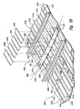
- FIGs 2A-2C together illustrate a method of joining the first barrel section 104a to the second barrel section 104b in accordance with an embodiment of the invention.
- this view is a partially exploded, enlarged isometric view looking outwardly at a portion of the second splice joint 106b from within the fuselage 102 ( Figure 1 ).
- the portion of the first barrel section 104a illustrated in Figure 2A includes a first panel portion 210a.
- the portion of the second barrel section 104b illustrated in Figure 2A includes a second panel portion 210b positioned in edgewise alignment with the first panel portion 210a.
- the panel portions 210 can be at least generally similar in structure and function to the panel assemblies.
- the first panel portion 210a can include a plurality of stiffeners 214 (identified individually as stiffeners 214a-214e) attached to the first skin 112a.
- Each of the stiffeners 214 can include a raised portion 224 projecting away from the first skin 112a, and a plurality of flange portions (identified individually as first flange portions 226a and second flange portions 226b) attached directly to the first skin 112a.
- the stiffeners 214 have hat-shaped cross-sections. In other embodiments, however, the stiffeners 214 can have other cross-sectional shapes, including "L" shapes, "C” shapes, inverted “T” shapes, "I” shapes, etc.
- the panel portions 210 can include other features.
- the stiffeners 214 can be positioned on the first skin 112a so that the first flange portions 226a of one stiffener 214 are aligned with the corresponding second flange portions 226b of an adjacent stiffener 214.
- the flange portions 226 can form a plurality of at least approximately continuous support surfaces 228 (identified individually as support surfaces 228a and 228b) extending between the raised portions 224 of the stiffeners 214.
- the first panel portion 210a can further include part of a support member or frame 216a.
- the frame 216a is a two-piece frame that includes a first frame section 218 and a second frame section 219.
- the first frame section 218 can be attached directly to the support surfaces 228 as described in detail in U.S. Patent Application No. 10/851,381 .
- the first frame section 218 can be attached to the first panel portion 210a using other methods.
- the first panel portion 210a can include parts of other frames composed of more or fewer frame sections.
- the frame 216a can be omitted.
- the second panel portion 210b can be at least generally similar in structure and function to the first panel portion 210a described above. Accordingly, the second panel portion 210b can include a plurality of stiffeners 214 (identified individually as stiffeners 214f-j) attached to the second skin 112b. The second panel portion 210b can further include a second frame 216b that is attached to flange portions of the stiffeners 214 in the manner described above for the first panel portion 210a.
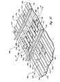
- an elongate strap 220 is attached to a first edge region 213a of the first skin 112a and an adjacent second edge region 213b of the second skin 112b to splice the first skin 112a to the second skin 112b.
- the strap 220 is attached to the inner side of the respective skins 112 to maintain a smooth, aerodynamic surface on the exterior of the fuselage 102 ( Figure 1 ).
- the strap 220 can include composite materials, such as graphite-epoxy or similar material.
- the strap 220 can include other materials, including metallic materials such as aluminum, titanium, steel, etc.
- the strap 220 can be attached to the skins 112 with a plurality of fasteners 221 extending through the strap 220 and the skins 112. In other embodiments, the strap 220 can be bonded to the skins 112, or bonded and fastened to the skins 112. Further, in embodiment, the strap 220 can extend continuously, or at least approximately continuously, around the splice joint 106b. In other embodiments, the strap 220 can be segmented around the splice joint 106b. For example, in one embodiment, the splice joint 106b can include six segments of the strap 220. In other embodiments, more (e.g., eight) or less segments of the strap 220 can be used.
- the strap 220 can be at least approximately as thick as the skins 112, but thicker than the adjacent flange portions 226 of the stiffeners 214.
- shim pads or fillers 222 are positioned on the flange portions 226 adjacent to the strap 220.
- the fillers 222 can include composite materials, including graphite-epoxy or similar materials.
- the fillers 222 can include aluminum and other metals.
- the strap 220, the skins 112, and/or the flange portions 226 can have other relative thicknesses and/or the fillers 222 can be omitted.
- a plurality of fittings 230 are positioned on the strap 220 and extend across the splice joint 106b between the stiffeners 214.
- a first end portion 232a of each fitting 230 overlays the corresponding first filler 222a and the flange portions 226 of the adjacent stiffeners 214.
- a second end portion 232b of each fitting 230 overlays the corresponding second filler 222b and the flange portions 226 of the adjacent stiffeners 214.
- each of the fittings 230 has a channel or "U-shaped" cross section that includes a base portion 234, a first upstanding edge portion 236a positioned toward a first side of the base portion 234, and a second upstanding edge portion 236b positioned toward a second side of the base portion 234.
- the fittings 230 can have other cross-sectional shapes, including "C” shapes, "L” shapes, inverted “ Pi " shapes, and flat shapes, to name a few.
- a plurality of fasteners 238 extending through the fittings 230 and the underlying structures attach the fittings 230 to the underlying structures to form a structural load path across the splice joint 106b.
- the fittings 230, the stiffeners 214, the strap 220, and the skins 112 can include composite materials, including graphite-epoxy and/or other suitable composite materials.
- the skins 112 can be manufactured with toughened epoxy resin and carbon fibers, e.g., intermediate carbon fibers from Toray Composites America, Inc. of 19002 50th Avenue East, Tacoma, WA 98446.
- the skins 112 can include fiber tape pre-impregnated with resin (i.e., "prepreg") and outer plies of prepreg fabric.
- the strap 220 and the fittings 230 can also be manufactured from epoxy resin and carbon fibers.
- the skins 112, the strap 220, and the fittings 230 can have quasi-isotropic lay-ups, i.e., lay-ups having an equal (or approximately equal) number of plies with 0, +45, -45, and 90 degree orientations.
- the stiffeners 214 can have axial-dominated fiber orientations. In other embodiments, the skins 112, the strap 220, the fittings 230, and the stiffeners 214 can have other fiber orientations.
- fittings 230 and the underlying structures will have at least generally similar coefficients of thermal expansion.
- temperature fluctuations experienced during operation of the aircraft 100 will not cause disparate thermal expansion between the fittings 230 and the underlying structures, and hence will not induce significant stresses in the splice joint 106b.
- the fittings 230 can include metal materials such as aluminum, titanium, steel, etc. The use of metals may be appropriate in those situations in which the aircraft is not expected to experience wide temperature fluctuations during operation.
- the skins 112, the strap 220, the fittings 230, and the stiffeners 214, and combinations thereof can include other materials, including hybrid materials such as fiber/metal laminates.
- Such laminates include fiberglass/aluminum laminates and titanium reinforced graphite laminates (Ti/Gr).
- Ti/Gr titanium reinforced graphite laminates
- One hybrid laminate that includes alternating layers of aluminum and fiberglass is referred to as "GLARETM.” This laminate may offer better fatigue properties than conventional aluminum.
- a Ti/Gr laminate may offer weight advantages over conventional aluminum or graphite-epoxy, but this laminate may also be more expensive.
- One feature of the splice joint 106b illustrated in Figure 2C is that the fittings 230 overlap the strap 220.
- One advantage of this feature is that it provides a fail-safe, redundant load path in the unlikely event that a crack or other structural flaw propagates through a portion of the strap 220. In such an event, the fittings 230 alone can carry the structural load across the splice joint 106b. In addition, the fittings 230 also provide a redundant load path across the splice joint 106b from where the stiffeners 214 terminate. Further, if a segmented strap 220 is used, then the fittings 230 can also be used as splice plates for adjacent strap segments. Another feature of the splice joint 106b is that the ends of the stiffeners 214 are left open. One advantage of this feature is that it enables moisture caused by condensation and other sources to escape the stiffeners 214 for sufficient drainage.
- fittings 230 of the illustrated embodiment are the first and second upstanding edge portions 236a and236b.
- the upstanding edge portions 236 can add stiffness to the fittings 230, and can be positioned proximate to the raised portions 224 of the stiffeners 214.
- One advantage of this configuration is that it can increase the stability of the splice joint 106b, especially under compression loads.
- the raised portions 224 of opposing stiffeners 214 are not spliced together across the splice joint 106b.
- One advantage of this feature is that it makes the fittings 230 relatively easy to install because the raised portions 224 do not have to be in perfect alignment. While the raised portions 224 could be spliced together in other embodiments, doing so would most likely add time and cost to manufacturing of the splice joint because of the various alignment and shimming considerations involved. Further, splicing the raised portions 224 together could close off the ends of the stiffeners 214, thereby preventing sufficient water drainage and preventing visual inspection of any fasteners positioned under the raised portions 224.
- the splice joint 106b of the illustrated embodiment is built up from a number of separate parts (e.g., the strap 220 and the fittings 230), in other embodiments, two or more of these parts can be integrated into a single part that performs the function and/or has the features of the two or more parts.
- the splice joint 106b can be at least partially formed by a single part that integrates the features of the strap 220 and the fittings 230.
- the splice joint 106b can include a single part that integrates the features of the strap 220 and the adjacent fillers 222.
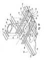
- Figures 3A-3C together illustrate a method of joining the first barrel section 104a to the second barrel section 104b in the vicinity of one of the window cutouts 140, in accordance with an embodiment of the invention.
- this view is a partially exploded, enlarged isometric view looking outwardly at a portion of the second splice joint 106b around the window cutout 140.
- the portion of the first barrel section 104a illustrated in Figure 3A includes a third panel portion 310a.
- the portion of the second barrel section 104b illustrated in Figure 3A includes a fourth panel portion 310b positioned in edgewise alignment with the third panel portion 310a.
- the panel portions 310 can be at least generally similar in structure and function to the panel portions 210 described in detail above with reference to Figures 2A-2C .
- the third panel portion 310a can include a plurality of stiffeners 214 (identified individually as stiffeners 214k-214m) attached to the first skin 112a.
- the fourth panel portion 310b can include a plurality of stiffeners 214 (identified individually as stiffeners 214n-214p) attached to the second skin 112b.
- the window cutout 140 is formed in a third edge region 313a of the first skin 112a, and in an adjacent fourth edge region 313b of the second skin 112b.
- an elongate strap 320 is attached to the third edge region 313a of the first skin 112a and the adjacent fourth edge region 313b of the second skin 112b.
- the strap 320 can be at least generally similar in structure and function to the strap 220 described above with reference to Figures 2A-2C .
- the aperture 324 is aligned with the window cutout 140 and the strap 320 is attached to the skins 112 with a plurality of the fasteners 221.
- the strap 320 can be bonded to the skins 112, or bonded and fastened to the skins 112.
- One feature of the strap 320 is that the aperture 324 extends completely around the window cutout 140.
- One advantage of this feature is that the strap 320 acts as a one-piece doubler, thereby providing an efficient load path around the window cutout 140.
- a further advantage of this feature is that it reduces part count by combining the window doubler feature with the splice strap feature in a single, integrated part.
- the strap 320 is thicker than the adjacent flange portions 226 of the stiffeners 214.
- the first fillers 222a and the second fillers 222b are positioned on the flange portions 226 adjacent to the strap 320 in those portions of the splice joint 106b positioned away from the window cutout 140.
- Narrower fillers 322 are positioned on the stiffener flange portions 226 in those areas proximate to the window cutout 140.
- a plurality of the fittings 230 extend across the splice joint 106b in the stiffener bays away from the window cutout 140 as described above with reference to Figures 2A-2C .
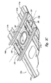
- Narrower fittings 330 are attached across the splice joint 106b in similar fashion at opposing ends of the window cutout 140.
- the narrow fittings 330 of the illustrated embodiment have "L" shaped cross sections. In other embodiments, however, the narrower fittings 330 can have other cross sectional shapes, including "U" shapes, "C" shapes, and flat shapes.
- a window frame 350 can be fastened or otherwise attached to the strap 320 and any underlying structures around the window cutout 140.
- the window frame 350 can be machined or otherwise formed from a high-strength metal material, such as aluminum.
- the window frame 350 can include composites and/or other suitable materials.
- FIG. 4 is a cross-sectional end view of the splice joint 106b taken substantially along line 4-4 in Figure 2C . This view illustrates that, in this embodiment, the fittings 230 are positioned over the strap 220, and the fasteners 238 extend through the fittings 230, the strap 220, and the skin 112b. This view further illustrates that the fittings 230 are positioned between, but proximate to, respective stiffeners 214.
Description
- The following disclosure relates generally to shell structures and, more particularly, to splice joints for joining composite fuselage sections and other shell structures together.
- The primary structural elements of large passenger jets and other large aircraft are typically made from metal. Fuselage shells for such aircraft, for example, are typically manufactured from high-strength aluminum alloys or similar metals. In an effort to increase performance, however, many aircraft manufacturers are turning to fiber-reinforced resin materials (i.e., "composite" materials) that have relatively high strength-to-weight ratios. Conventional composite materials typically include glass, carbon, or polyaramide fibers in a matrix of epoxy or another type of resin. The use of such materials for primary structures has mostly been limited to smaller aircraft, such as fighter aircraft, high-performance private aircraft, and business jets.
- One known method for manufacturing business jet airframes with composite materials is employed by the Raytheon Aircraft Company of Wichita, Kansas, to manufacture the Premier I and Hawker Horizon business jets. This method involves wrapping carbon fibers around a rotating mandrel with an automated fiber placement system. The mandrel provides the basic shape of a longitudinal fuselage section. The carbon fibers are preimpregnated with a thermoset epoxy resin, and are applied over the rotating mandrel in multiple plies to form an interior skin of the fuselage section. The interior skin is then covered with a layer of honeycomb core. The fiber placement system then applies additional plies of preimpregnated carbon fibers over the honeycomb core to form an exterior skin that results in a composite sandwich structure.
- The Premier I fuselage includes two 360-degree sections formed in the foregoing manner. The Hawker Horizon fuselage includes three such sections formed in this manner. The two 1,78 m (70 inch) diameter sections of the Premier I fuselage are riveted and then bonded together at a circumferential splice joint to form the complete fuselage structure. The much larger Hawker Horizon fuselage, with an 2,13 m (84 inch) diameter, uses aluminum
splice plates at two circumferential joints to join the three fuselage sections together into a complete structure. - To precisely install the aluminum splice plates on the Hawker Horizon fuselage, Raytheon created a special, automated splice machine. This machine aligns the three fuselage sections using a computer-aided laser alignment system, and then drills attachment holes through the aluminum splice plates and the underlying sandwich structure. The machine then probes each hole for size quality and records statistical process control data on each hole. The drill heads also apply sealant and install hi-shear fasteners in approximately 1,800 places along each of the splice joints. (See Raytheon Aircraft news release at http://www.beechcraft.de/presse/2000/100900b.htm entitled "RAYTHEON AIRCRAFT'S HAWKER HORIZON REACHES FUSELAGE MILESTONE," October 9, 2000).
- Document
US 5 518 208 discloses a shell structure comprising a first and a second aircraft skins, and forward and aft stringers. Said stringers are joined to bulkhead members by stringer splice fittings to form a framework to which skin splice plates are attached. The first and second aircraft skins will then finally attach the skin splice plates. - The present invention is directed generally toward structures and methods for joining composite fuselage sections and other panel assemblies together. A shell structure configured in accordance with one aspect of the invention is described in
claim 1. - A method for manufacturing a shell structure in accordance with another aspect of the invention is described in claim 32.
-
-
Figure 1 is an isometric view of an aircraft having a composite fuselage configured in accordance with an embodiment of the invention. -
Figures 2A-2C together illustrate a method of joining a first fuselage barrel section to a second fuselage barrel section in accordance with an embodiment of the invention. -
Figures 3A-3C together illustrate a method of joining the first fuselage barrel section to the second fuselage barrel section in the vicinity of a window cutout, in accordance with another embodiment of the invention. -
Figure 4 is a cross-sectional end view of the splice joint ofFigure 2C taken substantially along line 4-4 inFigure 2C . - The following disclosure describes structures and methods for joining composite fuselage sections and other panel assemblies together. Certain details are set forth in the following description and in
Figures 1-3C to provide a thorough understanding of various embodiments of the invention. Other details describing well-known structures and systems often associated with composite parts and related assembly techniques are not set forth in the following disclosure to avoid unnecessarily obscuring the description of the various embodiments of the invention. - Many of the details, dimensions, angles, and other features shown in the Figures are merely illustrative of particular embodiments of the invention. Accordingly, other embodiments can have other details, dimensions, angles, and features without departing from the scope of the present invention. In addition, further embodiments of the invention can be practiced without several of the details described below.
- In the Figures, identical reference numbers identify identical or at least generally similar elements. To facilitate the discussion of any particular element, the most significant digit or digits of any reference number refer to the Figure in which that element is first introduced. For example, element 106 is first introduced and discussed with reference to
Figure 1 . -
Figure 1 is an isometric view of anaircraft 100 having acomposite fuselage 102 configured in accordance with an embodiment of the invention. In one aspect of this embodiment, thefuselage 102 includes a plurality of composite barrel sections 104 (identified individually asbarrel sections 104a-e) joined together by a plurality of corresponding splice joints 106 (identified individually assplice joints 106a-f). Each of the barrel sections 104 includes a composite skin 112 (identified individually ascomposite skins 112a-112e) extending 360 degrees around alongitudinal axis 108. In the illustrated embodiment, each of the composite skins 112 can have a cross-sectional width of at least about 3,04 m (10 feet) such as about 4,57 m (15 feet) to about 10,67 m (35 feet) . In one embodiment, for example,
the composite skins 112 can have a cross-sectional width of about 5,48 m (18 feet). Throughout
this disclosure, the term "barrel section" is used for convenience to refer to any shell structure extending 360 degrees around an axis. Accordingly, the term is not limited to cylindrical structures or structures having barrel shapes, but can include structures having circular, elliptical, oval, egg-shaped, rectilinear, tapered, or other cross-sectional shapes. In addition, in one embodiment, the barrel sections 104 can be "one-piece" barrel sections in which the composite skins 112 are "one-piece" skins extending continuously for 360 degrees around the axis. In other embodiments, however, the skins 112 can be formed from two or more skin segments spliced or otherwise joined together to form the full 360-degree barrel section. - The
fuselage 102 can further include apassenger cabin 103 configured to hold a plurality ofpassenger seats 105 ranging in number from about 50 to about 700 seats. For example, in the illustrated embodiment, thepassenger cabin 103 can hold from about 150 to about 600passenger seats 105. In other embodiments, thepassenger cabin 103 can be configured to hold more or fewer passenger seats without departing from the spirit or scope of the present disclosure. Each of the barrel sections 104 can include a plurality ofwindow cutouts 140 to provide the passengers seated in thepassenger cabin 103 with views out of theaircraft 100. -
Figures 2A-2C together illustrate a method of joining thefirst barrel section 104a to thesecond barrel section 104b in accordance with an embodiment of the invention. Referring first toFigure 2A , this view is a partially exploded, enlarged isometric view looking outwardly at a portion of thesecond splice joint 106b from within the fuselage 102 (Figure 1 ). The portion of thefirst barrel section 104a illustrated inFigure 2A includes afirst panel portion 210a. The portion of thesecond barrel section 104b illustrated inFigure 2A includes asecond panel portion 210b positioned in edgewise alignment with thefirst panel portion 210a. In one embodiment, the panel portions 210 can be at least generally similar in structure and function to the panel assemblies. - For example, the
first panel portion 210a can include a plurality of stiffeners 214 (identified individually as stiffeners 214a-214e) attached to thefirst skin 112a. Each of the stiffeners 214 can include a raisedportion 224 projecting away from thefirst skin 112a, and a plurality of flange portions (identified individually asfirst flange portions 226a andsecond flange portions 226b) attached directly to thefirst skin 112a. In the illustrated embodiment, the stiffeners 214 have hat-shaped cross-sections. In other embodiments, however, the stiffeners 214 can have other cross-sectional shapes, including "L" shapes, "C" shapes, inverted "T" shapes, "I" shapes, etc. In yet other embodiments, the panel portions 210 can include other features. - The stiffeners 214 can be positioned on the
first skin 112a so that thefirst flange portions 226a of one stiffener 214 are aligned with the correspondingsecond flange portions 226b of an adjacent stiffener 214. By aligning the flange portions 226 in the foregoing manner, the flange portions 226 can form a plurality of at least approximately continuous support surfaces 228 (identified individually assupport surfaces 228a and 228b) extending between the raisedportions 224 of the stiffeners 214. - The
first panel portion 210a can further include part of a support member orframe 216a. In the illustrated embodiment, theframe 216a is a two-piece frame that includes afirst frame section 218 and asecond frame section 219. Thefirst frame section 218 can be attached directly to the support surfaces 228 as described in detail inU.S. Patent Application No. 10/851,381 . In other embodiments, thefirst frame section 218 can be attached to thefirst panel portion 210a using other methods. In still further embodiments, thefirst panel portion 210a can include parts of other frames composed of more or fewer frame sections. Alternatively, theframe 216a can be omitted. - The
second panel portion 210b can be at least generally similar in structure and function to thefirst panel portion 210a described above. Accordingly, thesecond panel portion 210b can include a plurality of stiffeners 214 (identified individually asstiffeners 214f-j) attached to thesecond skin 112b. Thesecond panel portion 210b can further include asecond frame 216b that is attached to flange portions of the stiffeners 214 in the manner described above for thefirst panel portion 210a. - Referring next to
Figure 2B , anelongate strap 220 is attached to afirst edge region 213a of thefirst skin 112a and an adjacentsecond edge region 213b of thesecond skin 112b to splice thefirst skin 112a to thesecond skin 112b. Thestrap 220 is attached to the inner side of the respective skins 112 to maintain a smooth, aerodynamic surface on the exterior of the fuselage 102 (Figure 1 ). In one embodiment, thestrap 220 can include composite materials, such as graphite-epoxy or similar material. In other embodiments, thestrap 220 can include other materials, including metallic materials such as aluminum, titanium, steel, etc. Thestrap 220 can be attached to the skins 112 with a plurality offasteners 221 extending through thestrap 220 and the skins 112. In other embodiments, thestrap 220 can be bonded to the skins 112, or bonded and fastened to the skins 112. Further, in embodiment, thestrap 220 can extend continuously, or at least approximately continuously, around the splice joint 106b. In other embodiments, thestrap 220 can be segmented around the splice joint 106b. For example, in one embodiment, the splice joint 106b can include six segments of thestrap 220. In other embodiments, more (e.g., eight) or less segments of thestrap 220 can be used. - In the illustrated embodiment, the
strap 220 can be at least approximately as thick as the skins 112, but thicker than the adjacent flange portions 226 of the stiffeners 214. To avoid a step between adjacent surfaces, shim pads or fillers 222 (identified individually asfirst fillers 222a andsecond fillers 222b) are positioned on the flange portions 226 adjacent to thestrap 220. In one embodiment, the fillers 222 can include composite materials, including graphite-epoxy or similar materials. In other embodiments, the fillers 222 can include aluminum and other metals. In yet other embodiments, thestrap 220, the skins 112, and/or the flange portions 226 can have other relative thicknesses and/or the fillers 222 can be omitted. - Referring next to
Figure 2C , a plurality offittings 230 are positioned on thestrap 220 and extend across the splice joint 106b between the stiffeners 214. Afirst end portion 232a of each fitting 230 overlays the correspondingfirst filler 222a and the flange portions 226 of the adjacent stiffeners 214. Similarly, asecond end portion 232b of each fitting 230 overlays the correspondingsecond filler 222b and the flange portions 226 of the adjacent stiffeners 214. In the illustrated embodiment, each of thefittings 230 has a channel or "U-shaped" cross section that includes abase portion 234, a first upstanding edge portion 236a positioned toward a first side of thebase portion 234, and a secondupstanding edge portion 236b positioned toward a second side of thebase portion 234. In other embodiments, thefittings 230 can have other cross-sectional shapes, including "C" shapes, "L" shapes, inverted "Pi" shapes, and flat shapes, to name a few. A plurality offasteners 238 extending through thefittings 230 and the underlying structures (i.e., the fillers 222, the flange portions 226, thestrap 220, and the skins 112) attach thefittings 230 to the underlying structures to form a structural load path across the splice joint 106b. - The
fittings 230, the stiffeners 214, thestrap 220, and the skins 112 can include composite materials, including graphite-epoxy and/or other suitable composite materials. For example, in one embodiment, the skins 112 can be manufactured with toughened epoxy resin and carbon fibers, e.g., intermediate carbon fibers from Toray Composites America, Inc. of 19002 50th Avenue East, Tacoma, WA 98446. In this embodiment, the skins 112 can include fiber tape pre-impregnated with resin (i.e., "prepreg") and outer plies of prepreg fabric. In another embodiment, thestrap 220 and thefittings 230 can also be manufactured from epoxy resin and carbon fibers. The skins 112, thestrap 220, and thefittings 230 can have quasi-isotropic lay-ups, i.e., lay-ups having an equal (or approximately equal) number of plies with 0, +45, -45, and 90 degree orientations. The stiffeners 214 can have axial-dominated fiber orientations. In other embodiments, the skins 112, thestrap 220, thefittings 230, and the stiffeners 214 can have other fiber orientations. - One advantage of using composite materials instead of metals is that the
fittings 230 and the underlying structures (e.g., the skins 112 and the stiffeners 214) will have at least generally similar coefficients of thermal expansion. As a result, temperature fluctuations experienced during operation of the aircraft 100 (Figure 1 ) will not cause disparate thermal expansion between thefittings 230 and the underlying structures, and hence will not induce significant stresses in the splice joint 106b. In other embodiments, however, thefittings 230 can include metal materials such as aluminum, titanium, steel, etc. The use of metals may be appropriate in those situations in which the aircraft is not expected to experience wide temperature fluctuations during operation. - In addition to composites and metal materials, in yet other embodiments, the skins 112, the
strap 220, thefittings 230, and the stiffeners 214, and combinations thereof, can include other materials, including hybrid materials such as fiber/metal laminates. Such laminates include fiberglass/aluminum laminates and titanium reinforced graphite laminates (Ti/Gr). One hybrid laminate that includes alternating layers of aluminum and fiberglass is referred to as "GLARE™." This laminate may offer better fatigue properties than conventional aluminum. A Ti/Gr laminate may offer weight advantages over conventional aluminum or graphite-epoxy, but this laminate may also be more expensive. - One feature of the splice joint 106b illustrated in
Figure 2C is that thefittings 230 overlap thestrap 220. One advantage of this feature is that it provides a fail-safe, redundant load path in the unlikely event that a crack or other structural flaw propagates through a portion of thestrap 220. In such an event, thefittings 230 alone can carry the structural load across the splice joint 106b. In addition, thefittings 230 also provide a redundant load path across the splice joint 106b from where the stiffeners 214 terminate. Further, if asegmented strap 220 is used, then thefittings 230 can also be used as splice plates for adjacent strap segments. Another feature of the splice joint 106b is that the ends of the stiffeners 214 are left open. One advantage of this feature is that it enables moisture caused by condensation and other sources to escape the stiffeners 214 for sufficient drainage. - One feature of the
fittings 230 of the illustrated embodiment are the first and second upstanding edge portions 236a and236b. The upstanding edge portions 236 can add stiffness to thefittings 230, and can be positioned proximate to the raisedportions 224 of the stiffeners 214. One advantage of this configuration is that it can increase the stability of the splice joint 106b, especially under compression loads. - Yet another feature of the illustrated embodiment is that the raised
portions 224 of opposing stiffeners 214 are not spliced together across the splice joint 106b. One advantage of this feature is that it makes thefittings 230 relatively easy to install because the raisedportions 224 do not have to be in perfect alignment. While the raisedportions 224 could be spliced together in other embodiments, doing so would most likely add time and cost to manufacturing of the splice joint because of the various alignment and shimming considerations involved. Further, splicing the raisedportions 224 together could close off the ends of the stiffeners 214, thereby preventing sufficient water drainage and preventing visual inspection of any fasteners positioned under the raisedportions 224. - Although the splice joint 106b of the illustrated embodiment is built up from a number of separate parts (e.g., the
strap 220 and the fittings 230), in other embodiments, two or more of these parts can be integrated into a single part that performs the function and/or has the features of the two or more parts. For example, in one other embodiment, the splice joint 106b can be at least partially formed by a single part that integrates the features of thestrap 220 and thefittings 230. In another embodiment, the splice joint 106b can include a single part that integrates the features of thestrap 220 and the adjacent fillers 222. Although integrating parts may have the advantages of reducing part count and/or increasing strength, using separate parts may have the advantage of simplifying part construction and/or simplifying installation procedures. -
Figures 3A-3C together illustrate a method of joining thefirst barrel section 104a to thesecond barrel section 104b in the vicinity of one of thewindow cutouts 140, in accordance with an embodiment of the invention. Referring first toFigure 3A , this view is a partially exploded, enlarged isometric view looking outwardly at a portion of the second splice joint 106b around thewindow cutout 140. The portion of thefirst barrel section 104a illustrated inFigure 3A includes athird panel portion 310a. The portion of thesecond barrel section 104b illustrated inFigure 3A includes afourth panel portion 310b positioned in edgewise alignment with thethird panel portion 310a. The panel portions 310 can be at least generally similar in structure and function to the panel portions 210 described in detail above with reference toFigures 2A-2C . For example, thethird panel portion 310a can include a plurality of stiffeners 214 (identified individually asstiffeners 214k-214m) attached to thefirst skin 112a. Similarly, thefourth panel portion 310b can include a plurality of stiffeners 214 (identified individually asstiffeners 214n-214p) attached to thesecond skin 112b. In one aspect of the illustrated embodiment, however, thewindow cutout 140 is formed in athird edge region 313a of thefirst skin 112a, and in an adjacentfourth edge region 313b of thesecond skin 112b. - Referring next to
Figure 3B , anelongate strap 320 is attached to thethird edge region 313a of thefirst skin 112a and the adjacentfourth edge region 313b of thesecond skin 112b. With the exception of anaperture 324 that extends through a flared-out portion of thestrap 320, thestrap 320 can be at least generally similar in structure and function to thestrap 220 described above with reference toFigures 2A-2C . For installation, theaperture 324 is aligned with thewindow cutout 140 and thestrap 320 is attached to the skins 112 with a plurality of thefasteners 221. In other embodiments, thestrap 320 can be bonded to the skins 112, or bonded and fastened to the skins 112. - One feature of the
strap 320 is that theaperture 324 extends completely around thewindow cutout 140. One advantage of this feature is that thestrap 320 acts as a one-piece doubler, thereby providing an efficient load path around thewindow cutout 140. A further advantage of this feature is that it reduces part count by combining the window doubler feature with the splice strap feature in a single, integrated part. - In the illustrated embodiment, the
strap 320 is thicker than the adjacent flange portions 226 of the stiffeners 214. To avoid a step between adjacent surfaces, thefirst fillers 222a and thesecond fillers 222b are positioned on the flange portions 226 adjacent to thestrap 320 in those portions of the splice joint 106b positioned away from thewindow cutout 140. Narrower fillers 322 (identified individually asthird fillers 322a andfourth fillers 322b) are positioned on the stiffener flange portions 226 in those areas proximate to thewindow cutout 140. - Referring next to
Figure 3C , a plurality of thefittings 230 extend across the splice joint 106b in the stiffener bays away from thewindow cutout 140 as described above with reference toFigures 2A-2C .Narrower fittings 330 are attached across the splice joint 106b in similar fashion at opposing ends of thewindow cutout 140. Thenarrow fittings 330 of the illustrated embodiment have "L" shaped cross sections. In other embodiments, however, thenarrower fittings 330 can have other cross sectional shapes, including "U" shapes, "C" shapes, and flat shapes. Awindow frame 350 can be fastened or otherwise attached to thestrap 320 and any underlying structures around thewindow cutout 140. In one embodiment, thewindow frame 350 can be machined or otherwise formed from a high-strength metal material, such as aluminum. In other embodiments, thewindow frame 350 can include composites and/or other suitable materials. - One feature of the embodiments described above and illustrated in
Figures 3A-3C is that the splice joint 106b extends through the middle of thewindow cutout 140. One advantage of this feature is that it provides design flexibility. For example, this feature allows window patterns and barrel section lengths to be selected irrespective of splice location.Figure 4 is a cross-sectional end view of the splice joint 106b taken substantially along line 4-4 inFigure 2C . This view illustrates that, in this embodiment, thefittings 230 are positioned over thestrap 220, and thefasteners 238 extend through thefittings 230, thestrap 220, and theskin 112b. This view further illustrates that thefittings 230 are positioned between, but proximate to, respective stiffeners 214. - From the foregoing, it will be appreciated that specific embodiments of the invention have been described herein for purposes of illustration, but that various modifications may be made without deviating from the scope of the invention. For example, aspects described in the context of particular vehicles, such as aircraft, can equally apply to other vehicles, such as helicopters, rockets, watercraft, etc. Further, aspects described in the context of particular embodiments can be combined or eliminated in other embodiments. Accordingly, the invention is not limited, except as by the appended claims.
Claims (43)
- A shell structure comprising:a first panel portion (210a), the first panel portion including:a first skin (112a); anda first stiffener (214a) attached to the first skin wherein the first stiffener includes a first flange portion (226a) directly attached to the first skin and a first raised portion (224) projecting away from the first skin;a second panel portion (210b) positioned adjacent to the first panel portion, the second panel portion including:a second skin (112b); anda second stiffener (214f) attached to the second skin wherein the second stiffener includes a second flange portion directly attached to the second skin and a second raised portion projecting away from the second skin; anda fitting (230a) extending across a first edge region (213a) of the first panel portion and a second edge region (213b) of the second panel portion, wherein a first end portion (232a) of the fitting overlays and is attached to the first flange portion of the first stiffener and the first skin and wherein a second end portion (232b) of the fitting overlays and is attached to the second flange portion of the second stiffener and the second skin to join the first panel portion to the second panel portion.
- The shell structure of claim 1 wherein the first stiffener is longitudinally aligned with the second stiffener.
- The shell structure of claim 1 wherein the first skin is positioned in edgewise alignment with the second skin.
- The shell structure of claim 1, further comprising a strap attached to a first edge region of the first skin and a second edge region of the second skin to splice the first skin to the second skin.
- The shell structure of claim 1, further comprising a strap attached to a first edge region of the first skin and a second edge region of the second skin to splice the first skin to the second skin, wherein at least a portion of the strap is sandwiched between the fitting and the first edge region of the first skin and the second edge region of the second skin.
- The shell structure of claim 1 wherein the first skin is a first composite skin of an aircraft fuselage, and wherein the second skin is a second composite skin of the aircraft fuselage.
- The shell structure of claim 1, wherein:the first panel portion further includes:a third stiffener having a third flange portion attached to the first skin and a third raised portion projecting away from the first skin;the second panel portion further includes:a fourth stiffener having a fourth flange portion attached to the second skin and a fourth raised portion projecting away from the second skin; andthe first end portion of the fitting overlays and is attached to the first flange portion of the first stiffener and the third flange portion of the third stiffener, and wherein the second end portion of the fitting overlays and is attached to the second flange portion of the second stiffener and the fourth flange portion of the fourth stiffener.
- The shell structure of claim 7 wherein at least one of the first flange portion of the first stiffener and the third flange portion of the third stiffener extends toward the other to form an at least approximately continuous surface extending between the first raised portion of the first stiffener and the third raised portion of the third stiffener, and wherein the approximately continuous surface is sandwiched between the first end portion of the fitting and the first skin.
- The shell structure of claim 7 further comprising a strap attached to a first edge region of the first skin and a second edge region of the second skin to splice the first skin to the second skin, wherein at least a portion of the strap is sandwiched between the fitting and the first edge region of the first skin and the second edge region of the second skin.
- The shell structure of claim 7 wherein the first and second panel portions form an exterior portion of a fuselage, and wherein the aircraft structure further comprises:the fuselage; andmeans for generating lift positioned at least proximate to the fuselage.
- The shell structure of claim 7 wherein the fitting has a U-shaped cross-section.
- The shell structure of claim 7 wherein the fitting has a base portion and at least one upstanding edge region, and wherein the base portion is fastened to the first flange portion of the first stiffener, the second flange portion of the second stiffener, the third flange portion of the third stiffener, and the fourth flange portion of the fourth stiffener.
- The shell structure of claim 7 wherein the fitting has a base portion, a first upstanding edge portion positioned toward a first side of the base portion, and a second upstanding edge portion positioned toward a second side of the base portion, wherein the first upstanding edge portion is positioned proximate to the first raised portion of the first stiffener and the second raised portion of the second stiffener, and wherein the second upstanding edge portion is positioned proximate to the third raised portion of the third stiffener and the fourth raised portion of the fourth stiffener.
- The shell structure of claim 7 wherein the first and second skins include composite materials.
- The shell structure of claim 7 wherein the first and second skins and the fitting include composite materials.
- The shell structure of claim 7 wherein at least the first and third stiffeners form enclosed passages with open ends.
- The shell structure of claim 7 wherein the first skin includes a first portion of a window cutout and the second skin includes a second portion of the window cutout.
- The shell structure of claim 6, wherein:the aircraft fuselage is aligned along a longitudinal axis,the first composite skin extends 360 degrees around the longitudinal axis;the second composite skin is positioned adjacent to the first composite skin and extends 360 degrees around the longitudinal axis; andthe first edge region of the first panel portion includes a first edge region of the first composite skin and the second edge region of the second panel portion includes a second edge region of the second composite skin.
- The shell structure of claim 18 wherein the first stiffener is longitudinally aligned with the second stiffener.
- The shell structure of claim 18, further comprising:a passenger cabin.
- The shell structure of claim 18 wherein the first composite skin at least partially forms a barrel section having a cross-sectional width of at least about 10 feet.
- The shell structure of claim 18 wherein the first edge region of the first composite skin includes a first portion of a window cutout, and wherein the second edge region of the second composite skin includes a second portion of the window cutout.
- The shell structure of claim 18 wherein the first edge region of the first composite skin includes a first portion of a window cutout, wherein the second edge region of the second composite skin includes a second portion of the window cutout, and wherein the aircraft fuselage further comprises a strap having an aperture aligned with the window cutout, the strap being fastened to the first edge region of the first composite skin and the second edge region of the second composite skin.
- The shell structure of claim 18, the shell structure further comprising:splice means separate from the fitting for attaching a first edge region of the first composite skin to a second edge region of the second composite skin.
- The shell structure of claim 24, further comprising:third stiffening means positioned adjacent to the first stiffening means for stiffening the first composite skin; andfourth stiffening means positioned adjacent to the second stiffening means for stiffening the second composite skin, wherein the fitting means extends across the splice means and structurally connects the first and third stiffening means to the second and fourth stiffening means.
- The shell structure of claim 24 wherein the fitting means are attached to the first and second flange portions but not to the first and second raised portions.
- The shell structure of claim 24 wherein the first composite skin at least partially forms a barrel section having a cross-sectional width of at least about 10 feet.
- The shell structure of claim 1, wherein:the first skin has a first edge cut-out portion; andthe second skin has a second edge cut-out portion, wherein the positioning of the second panel portion adjacent to the first panel portion is such that the first edge cut-out portion is aligned with the second edge cut-out portion.
- The shell structure of claim 28, further comprising a strap attached to a first edge region of the first skin and a second edge region of the second skin to splice the first skin to the second skin, wherein the strap includes an aperture aligned with the first edge portion cut-out and the second edge portion cut-out.
- The shell structure of claim 28, further comprising a strap attached to a first edge region of the first skin and a second edge region of the second skin to splice the first skin to the second skin, wherein the strap includes an aperture aligned with the first edge portion cut-out and the second edge portion cut-out, and wherein at least a portion of the strap is sandwiched between the fitting and the first edge region of the first skin and the second edge region of the second skin.
- The shell structure of claim 28 wherein the first skin is a first composite skin of an aircraft fuselage, wherein the second skin is a second composite skin of the aircraft fuselage, and wherein the first and second edge cut-out portions form a window cutout in the aircraft fuselage.
- A method for manufacturing a shell structure, the method comprising:positioning a first composite skin (112a) in edgewise alignment with a second composite skin (112b);providing a first stiffener (214a), wherein the first stiffener includes a first flange portion (226a) and a first raised portion (224);providing a second stiffener (214f), wherein the second stiffener includes a second flange portion and a second raised portion;attaching the first stiffener to the first composite skin by directly attaching the first flange portion to the first composite skin, where the raised portion of the first stiffener projects away from the first composite skin,attaching the second stiffener to the second composite skin by directly attaching the second flange portion to the second composite skin, where the raised portion of the second stiffener projects away from the second composite skin,overlaying and attaching a first end portion (232a) of a fitting (230a) to the first flange portion of the first stiffener and the first composite skin; andoverlaying and attaching a second end portion (232b) of the fitting to the second flange portion of the second stiffener and the second composite skin, thereby joining the first composite skin to the second composite skin.
- The method of claim 32, further comprising attaching a strap to a first edge region of the first composite skin and a second edge region of the second composite skin to splice the first and second composite skins together before the fitting is attached.
- The method of claim 32, further comprising attaching a strap to a first edge region of the first composite skin and a second edge region of the second composite skin to splice the first and second composite skins together before the fitting is attached, and wherein attaching the fitting includes sandwiching a portion of the strap between the fitting and the first edge region of the first composite skin and the second edge region of the second composite skin.
- The method of claim 32 wherein the first composite skin extends 360 degrees around a first axis, and wherein the second composite skin extends 360 degrees around a second axis.
- The method of claim 32 wherein attaching a first end of a fitting to the first stiffener and a second end of the fitting to the second stiffener includes leaving end portions of the first and second stiffeners open for liquid drainage.
- The method of claim 35 for manufacturing an aircraft fuselage, the method further comprising:positioning the first composite skin adjacent to the second composite skin so that the first and second axes are at least approximately aligned.
- The method of claim 37, further comprising:attaching at least a third stiffener to the first composite skin;attaching at least a fourth stiffener to the second composite skin; andattaching the first end portion of the fitting to the third stiffener and the second end portion of the fitting to the fourth stiffener.
- The method of claim 37, further comprising:attaching at least a third stiffener to the first composite skin so that the first flange portion of the first stiffener and a third flange portion of the third stiffener form an at least approximately continuous first support surface;attaching at least a fourth stiffener to the second composite skin so that the second flange portion of the second stiffener and a fourth flange portion of the fourth stiffener form an at least approximately continuous second support surface, wherein attaching a first end portion of a fitting to the first stiffener includes attaching the first end portion to the first support surface, and wherein attaching a second end portion of the fitting to the second stiffener includes attaching the second end portion to the second support surface.
- The method of claim 37 wherein positioning the first composite skin adjacent to the second composite skin includes positioning a first barrel section having a first width of about 15 feet or more with a second barrel section having a second width of about 15 feet or more.
- The method of claim 32 for manufacturing a shell structure, wherein:the first skin has a first edge cut-our portion,the second skin has a second edge cut-out portion; andpositioning the first skin in edgewise alignment with the second skin, the first edge cut-out portion is at least approximately aligned with the second edge cut-out portion.
- The method of claim 41, further comprising attaching a strap to a first edge region of the first skin and a second edge region of the second skin to splice the first and second skins together, wherein the strap includes an aperture at least approximately aligned with the first and second edge cut-out portions of the first and second skins.
- The method of claim 41, further comprising attaching a strap to a first edge region of the first skin and a second edge region of the second skin to splice the first and second skins together, wherein the strap includes an aperture at least approximately aligned with the first and second edge cut-out portions of the first and second skins, and wherein attaching the fitting includes sandwiching a portion of the strap between the fitting and the first edge region of the first skin and the second edge region of the second skin.
Applications Claiming Priority (2)
| Application Number | Priority Date | Filing Date | Title |
|---|---|---|---|
| US10/949,848 US7325771B2 (en) | 2004-09-23 | 2004-09-23 | Splice joints for composite aircraft fuselages and other structures |
| PCT/US2005/032737 WO2007001365A2 (en) | 2004-09-23 | 2005-09-14 | Splice joints for composite aircraft fuselages and other structures |
Publications (2)
| Publication Number | Publication Date |
|---|---|
| EP1794050A2 EP1794050A2 (en) | 2007-06-13 |
| EP1794050B1 true EP1794050B1 (en) | 2016-11-09 |
Family
ID=36072898
Family Applications (1)
| Application Number | Title | Priority Date | Filing Date |
|---|---|---|---|
| EP05858121.6A Active EP1794050B1 (en) | 2004-09-23 | 2005-09-14 | Splice joints for composite aircraft fuselages and other structures |
Country Status (6)
| Country | Link |
|---|---|
| US (6) | US7325771B2 (en) |
| EP (1) | EP1794050B1 (en) |
| JP (2) | JP5130045B2 (en) |
| CA (1) | CA2583535C (en) |
| ES (1) | ES2606242T3 (en) |
| WO (1) | WO2007001365A2 (en) |
Families Citing this family (139)
| Publication number | Priority date | Publication date | Assignee | Title |
|---|---|---|---|---|
| US8336596B2 (en) * | 2002-11-22 | 2012-12-25 | The Boeing Company | Composite lamination using array of parallel material dispensing heads |
| US8934702B2 (en) | 2003-12-02 | 2015-01-13 | The Boeing Company | System and method for determining cumulative tow gap width |
| US7289656B2 (en) * | 2003-12-02 | 2007-10-30 | The Boeing Company | Systems and methods for determining inconsistency characteristics of a composite structure |
| RU2270135C2 (en) * | 2004-03-04 | 2006-02-20 | Карклин Андрей Михайлович | Flying vehicle fuselage |
| US7527222B2 (en) * | 2004-04-06 | 2009-05-05 | The Boeing Company | Composite barrel sections for aircraft fuselages and other structures, and methods and systems for manufacturing such barrel sections |
| US7134629B2 (en) | 2004-04-06 | 2006-11-14 | The Boeing Company | Structural panels for use in aircraft fuselages and other structures |
| US7325771B2 (en) | 2004-09-23 | 2008-02-05 | The Boeing Company | Splice joints for composite aircraft fuselages and other structures |
| US7424902B2 (en) | 2004-11-24 | 2008-09-16 | The Boeing Company | In-process vision detection of flaw and FOD characteristics |
| US7503368B2 (en) | 2004-11-24 | 2009-03-17 | The Boeing Company | Composite sections for aircraft fuselages and other structures, and methods and systems for manufacturing such sections |
| US20060108048A1 (en) * | 2004-11-24 | 2006-05-25 | The Boeing Company | In-process vision detection of flaws and fod by back field illumination |
| US7837147B2 (en) | 2005-03-18 | 2010-11-23 | The Boeing Company | Systems and methods for reducing noise in aircraft fuselages and other structures |
| FR2883548B1 (en) * | 2005-03-23 | 2007-06-15 | Airbus France Sas | DEVICE AND METHOD FOR DISSYMMETRIC CARBON-METAL MIXED DISCHARGE |
| NL1030029C2 (en) * | 2005-09-26 | 2007-03-27 | Gtm Consulting B V | Method and device for gluing components to a composite molded part. |
| NL1030066C2 (en) * | 2005-09-29 | 2007-03-30 | Gtm Consulting B V | Method for manufacturing a molded part from a composite material. |
| FR2896768B1 (en) * | 2006-01-27 | 2009-10-09 | Eurocopter France | CONTROLLED FLAMBING ANTI-CRASH COMPOSITE STRUCTURE FOR AIRCRAFT. |
| DE102006044683A1 (en) * | 2006-02-07 | 2007-08-23 | Grob, Margret | Aircraft body and method for its production |
| WO2008054876A2 (en) * | 2006-05-15 | 2008-05-08 | Alcoa Inc. | Reinforced hybrid structures and methods thereof |
| DE102006025930B4 (en) * | 2006-06-02 | 2008-09-11 | Airbus Deutschland Gmbh | Hull structure and method of making a hull structure |
| DE102006026169B4 (en) * | 2006-06-06 | 2012-06-21 | Airbus Operations Gmbh | Aircraft fuselage structure and method for its manufacture |
| DE102006026170B4 (en) * | 2006-06-06 | 2012-06-21 | Airbus Operations Gmbh | Aircraft fuselage structure and method for its manufacture |
| DE102006026168A1 (en) | 2006-06-06 | 2008-01-31 | Airbus Deutschland Gmbh | Aircraft fuselage structure and method for its manufacture |
| DE102006026167B3 (en) * | 2006-06-06 | 2007-12-13 | Airbus Deutschland Gmbh | Lightweight structural panel |
| NL2000100C2 (en) * | 2006-06-13 | 2007-12-14 | Gtm Consulting B V | Laminate from metal sheets and plastic. |
| US7740306B2 (en) * | 2006-07-26 | 2010-06-22 | Utilicorp L.C. | Stiffeners for utility trailer structural panels |
| DE102006039290A1 (en) * | 2006-08-22 | 2008-03-13 | Airbus Deutschland Gmbh | Frame element for aircraft component assembly system, has connecting struts that are provided with recesses for receiving ribs of aircraft structure when frame element is attached to aircraft structure |
| NL2000232C2 (en) * | 2006-09-12 | 2008-03-13 | Gtm Consulting B V | Skin panel for an aircraft fuselage. |
| FR2906008B1 (en) * | 2006-09-15 | 2008-11-07 | Airbus France Sa | SMOOTH CHEST AND ORBITAL JUNCTION DEVICE |
| US7628358B2 (en) * | 2006-10-26 | 2009-12-08 | The Boeing Company | Wing panel structure |
| FR2910874B1 (en) * | 2007-01-02 | 2009-02-13 | Airbus France Sas | SMOOTH ASSEMBLIES AT THE LEVEL OF A CIRCUMFERENTIAL JUNCTION OF AN AIRCRAFT FUSELAGE. |
| FR2911112B1 (en) * | 2007-01-05 | 2009-02-13 | Airbus France Sas | FUSELAGE SECTION FOR AIRCRAFT AND AIRCRAFT COMPRISING SUCH A SECTION |
| US9511571B2 (en) | 2007-01-23 | 2016-12-06 | The Boeing Company | Composite laminate having a damping interlayer and method of making the same |
| US7787979B2 (en) * | 2007-03-14 | 2010-08-31 | The Boeing Company | Splicing fuselage sections without shims |
| DE102007018753B4 (en) * | 2007-04-20 | 2012-11-08 | Airbus Operations Gmbh | Fire protection room for aircraft passengers with the help of fuselage made of fiber-metal laminates |
| DE102007019821B4 (en) * | 2007-04-26 | 2012-11-22 | Airbus Operations Gmbh | Structural element of an aircraft fuselage |
| US20090211697A1 (en) * | 2007-05-15 | 2009-08-27 | Heinimann Markus B | Reinforced hybrid structures and methods thereof |
| US8388795B2 (en) | 2007-05-17 | 2013-03-05 | The Boeing Company | Nanotube-enhanced interlayers for composite structures |
| US20080296432A1 (en) * | 2007-06-04 | 2008-12-04 | Kernkamp Industries Corporation | Method of extending length of aircraft to increase interior space |
| US8043458B2 (en) * | 2007-06-21 | 2011-10-25 | Sikorsky Aircraft Corporation | Method of forming panels using an in-situ tape placement process and panels formed therefrom |
| DE102007028918A1 (en) * | 2007-06-22 | 2009-01-02 | Airbus Deutschland Gmbh | Method for producing a fuselage cell of an aircraft and device |
| DE102007029500B4 (en) * | 2007-06-25 | 2013-02-14 | Airbus Operations Gmbh | Method for coupling stiffening profile elements and structural component |
| US8042767B2 (en) * | 2007-09-04 | 2011-10-25 | The Boeing Company | Composite fabric with rigid member structure |
| US7998392B2 (en) * | 2007-09-25 | 2011-08-16 | The Boeing Company | Method for manufacturing and attachment of wing fairings |
| FR2922518B1 (en) * | 2007-10-18 | 2010-04-23 | Airbus France | AIRCRAFT STRUCTURE COMPRISING STIFF STOP JUNCTIONS |
| FR2922516B1 (en) * | 2007-10-18 | 2010-04-16 | Airbus France | LIGHTING OF OMEGA STIFFENERS AT THE CIRCUMFERENTIAL JUNCTION OF AN AIRCRAFT FUSELAGE |
| FR2922517B1 (en) * | 2007-10-18 | 2010-04-23 | Airbus France | AIRCRAFT COMPRISING SUNNY ARRESTOR JUNCTIONS AND METHOD OF MANUFACTURING SUCH A PLANE |
| DE102007052098A1 (en) * | 2007-10-31 | 2009-05-14 | Airbus Deutschland Gmbh | Crossbar for creating a fuselage cell and method for connecting two in particular wound CFRP fuselage sections |
| DE102008006834A1 (en) * | 2008-01-30 | 2009-10-15 | Airbus Deutschland Gmbh | Connecting arrangement for connecting two stiffening elements of different cross-sectional profile for an aircraft or spacecraft, and a shell component |
| DE102008008386A1 (en) * | 2008-02-09 | 2009-08-13 | Airbus Deutschland Gmbh | Method for producing an FVW component |
| US8499631B2 (en) * | 2008-02-15 | 2013-08-06 | The Boeing Company | Nondestructive inspection of aircraft stiffeners |
| DE102008010197B4 (en) | 2008-02-20 | 2012-03-22 | Airbus Operations Gmbh | Method for connecting two fuselage sections with the creation of a transverse joint and transverse joint connection |
| DE102008012282A1 (en) * | 2008-03-03 | 2009-09-17 | Airbus Deutschland Gmbh | Hull structure for airplane |
| DE102008012252B4 (en) | 2008-03-03 | 2014-07-31 | Airbus Operations Gmbh | Composite as well as aircraft or spacecraft with such a composite |
| DE102008013365B4 (en) * | 2008-03-10 | 2011-03-17 | Airbus Operations Gmbh | Transverse joint between two fuselage sections |
| US8220745B2 (en) * | 2008-04-14 | 2012-07-17 | Airbus Deutschland Gmbh | Connection arrangement for connecting a first and second reinforcing element for an aircraft or spacecraft, and a shell component |
| US7967250B2 (en) * | 2008-05-12 | 2011-06-28 | EMBRAER—Empresa Brasileira de Aeronáutica | Hybrid aircraft fuselage structural components and methods of making same |
| ES2352941B1 (en) * | 2008-05-16 | 2012-01-25 | Airbus Operations, S.L. | INTEGRATED AIRCRAFT STRUCTURE IN COMPOSITE MATERIAL |
| FR2931720B1 (en) * | 2008-06-02 | 2010-12-17 | Airbus France | METHOD FOR ORBITAL ASSEMBLY OF AIRCRAFT STRINGS IN COMPOSITE MATERIAL |
| JP4697279B2 (en) | 2008-09-12 | 2011-06-08 | ソニー株式会社 | Image display device and detection method |
| FR2936495B1 (en) * | 2008-09-30 | 2011-06-03 | Airbus France | ASSEMBLY OF PANELS FOR AIRCRAFT FUSELAGE. |
| FR2936488B1 (en) * | 2008-09-30 | 2011-04-15 | Airbus France | AIRCRAFT FUSELAGE TRUNK IN COMPOSITE MATERIAL WITH INTERNAL CONSTANT PROFILE |
| DE102008044049A1 (en) * | 2008-11-25 | 2010-06-02 | Airbus Deutschland Gmbh | Structural component of an aircraft or spacecraft and a fuselage component arrangement of an aircraft or spacecraft |
| US20100132880A1 (en) * | 2008-12-01 | 2010-06-03 | Kevin Patrick Kelleher | Composite honeycomb sandwich panel splicing |
| NL2002289C2 (en) * | 2008-12-04 | 2010-06-07 | Gtm Holding B V | Sandwich panel, support member for use in a sandwich panel and aircraft provided with such a sandwich panel. |
| FR2940785B1 (en) * | 2009-01-08 | 2012-10-26 | Airbus France | LONGITUDINAL JUNCTION FOR AIRCRAFT FUSELAGE PANELS IN COMPOSITE MATERIALS |
| DE102009009491A1 (en) * | 2009-02-18 | 2010-09-09 | Airbus Deutschland Gmbh | Method for producing a shell body |
| US8524356B1 (en) | 2009-03-09 | 2013-09-03 | The Boeing Company | Bonded patch having multiple zones of fracture toughness |
| US8540909B2 (en) | 2009-03-09 | 2013-09-24 | The Boeing Company | Method of reworking an area of a composite structure containing an inconsistency |
| US9492975B2 (en) | 2009-03-09 | 2016-11-15 | The Boeing Company | Structural bonded patch with tapered adhesive design |
| US8409384B2 (en) * | 2009-03-09 | 2013-04-02 | The Boeing Company | Predictable bonded rework of composite structures |
| US8449703B2 (en) * | 2009-03-09 | 2013-05-28 | The Boeing Company | Predictable bonded rework of composite structures using tailored patches |
| US8617694B1 (en) | 2009-03-09 | 2013-12-31 | The Boeing Company | Discretely tailored multi-zone bondline for fail-safe structural repair |
| ES2390318B1 (en) * | 2009-03-10 | 2013-09-16 | Airbus Operations, S.L. | CLOSED STRUCTURE IN COMPOSITE MATERIAL. |
| DE102009012429B4 (en) * | 2009-03-10 | 2012-08-30 | Telair International Gmbh | Floor module of a cargo deck in the fuselage of an aircraft |
| US20100233424A1 (en) * | 2009-03-10 | 2010-09-16 | The Boeing Company | Composite structures employing quasi-isotropic laminates |
| US8425710B2 (en) | 2009-03-13 | 2013-04-23 | The Boeing Company | Automated placement of vibration damping materials |
| DE102009013585B4 (en) | 2009-03-17 | 2012-01-26 | Airbus Operations Gmbh | Fuselage cell structure for a hybrid aircraft |
| ES2371951B1 (en) * | 2009-03-25 | 2012-11-21 | Airbus Operations, S.L. | PROVISION OF THE BOARD OF STRUCTURAL ELEMENTS OF A COMPOSITE MATERIAL. |
| DE102009014933A1 (en) | 2009-03-25 | 2010-10-07 | Airbus Operations Gmbh | Method for tolerance compensation between two components and tool for carrying out the method |
| DE102009021369A1 (en) | 2009-05-12 | 2010-11-18 | Airbus Operations Gmbh | Method for producing an aircraft fuselage and fuselage |
| ES2382765B1 (en) * | 2009-06-29 | 2013-05-03 | Airbus Operations, S.L. | AIRCRAFT NOTEBOOK DESIGN |
| FR2947522B1 (en) * | 2009-07-03 | 2011-07-01 | Airbus Operations Sas | FUSELAGE ELEMENT COMPRISING A FUSELAGE STRING AND JUNCTION MEANS, FUSELAGE PORTION, FUSELAGE AND AIRCRAFT |
| ES2376098B1 (en) * | 2009-07-24 | 2013-02-04 | Airbus Operations S.L. | PROCESS OF ASSEMBLY OF FUSELAGE SECTIONS OF AN AIRCRAFT. |
| US9079674B1 (en) * | 2009-09-18 | 2015-07-14 | Blue Origin, Llc | Composite structures for aerospace vehicles, and associated systems and methods |
| DE102009056533B4 (en) * | 2009-12-03 | 2015-02-26 | Deutsches Zentrum für Luft- und Raumfahrt e.V. | Fuselage component |
| DE102009056994B4 (en) | 2009-12-04 | 2020-03-19 | Airbus Defence and Space GmbH | Butt joint between fuselage sections and procedures |
| WO2011071939A2 (en) * | 2009-12-07 | 2011-06-16 | Global Aerosystems, Llc | Wing spar splice joint |
| CA2788948C (en) | 2010-02-05 | 2019-03-26 | Learjet Inc. | System and method for fabricating a composite material assembly |
| DE102010018932B4 (en) | 2010-04-30 | 2013-06-13 | Airbus Operations Gmbh | Perimeter stiffening for an aircraft fuselage |
| ES2400768B1 (en) * | 2010-06-30 | 2014-02-12 | Airbus Operations, S.L. | INTERNAL AIRCRAFT STRUCTURE IN COMPOSITE MATERIAL. |
| US8567722B2 (en) * | 2010-12-15 | 2013-10-29 | The Boeing Company | Splice and associated method for joining fuselage sections |
| FR2970942B1 (en) * | 2011-01-28 | 2013-02-22 | Airbus Operations Sas | CONNECTING STIFF FRAMES BETWEEN AN AIRCRAFT FUSELAGE AND A VESSEL HOUSING |
| FR2973773B1 (en) * | 2011-04-05 | 2013-11-29 | Airbus Operations Sas | METHOD FOR SLOWING THE PROPAGATION OF CRACKS IN A SECURE STRUCTURE AND A HIGHLY SECURE FRAME, ESPECIALLY A FUSELAGE |
| ES2401830B1 (en) * | 2011-06-29 | 2014-04-10 | Airbus Operations S.L. | FILLING PANELS FOR COATINGS OF AIRCRAFT FUEL TANKS. |
| FR2984274B1 (en) * | 2011-12-15 | 2014-06-27 | Airbus Operations Sas | SECURED BEAM, IN PARTICULAR A STRONG FUSELAGE FRAME, AS WELL AS AIRCRAFT FUSELAGE EQUIPPED WITH SUCH FRAMES |
| JP5924934B2 (en) | 2011-12-28 | 2016-05-25 | 三菱重工業株式会社 | Composite joint structure |
| US8740151B1 (en) * | 2012-01-03 | 2014-06-03 | The Boeing Company | Adjustable splice fitting for shimless connection of structual members |
| IN2014DN06519A (en) * | 2012-02-17 | 2015-06-12 | Saab Ab | |
| US8985514B2 (en) * | 2012-06-20 | 2015-03-24 | The Boeing Company | Composite structural panels and aircraft fuselages |
| US8939406B2 (en) * | 2012-07-02 | 2015-01-27 | The Boeing Company | Joining composite fuselage sections along window belts |
| US8985517B2 (en) * | 2012-10-26 | 2015-03-24 | Textron Innovations Inc. | Passive cooling of transmission using mast mounted heat pipes |
| US8960606B2 (en) | 2012-10-31 | 2015-02-24 | The Boeing Company | Circumference splice for joining shell structures |
| EP2730495B1 (en) * | 2012-11-13 | 2016-04-27 | Airbus Operations GmbH | Shell structure of a fuselage |
| EP2738085A1 (en) | 2012-11-30 | 2014-06-04 | Airbus Operations GmbH | Aircraft fuselage structure and method |
| DE102013202084A1 (en) * | 2013-02-08 | 2014-08-14 | Airbus Operations Gmbh | Vehicle with a planking |
| EP2767388A1 (en) * | 2013-02-15 | 2014-08-20 | Airbus Operations GmbH | Fibre reinforced plastic profiles having sections with different fibre types |
| DE102013102812B4 (en) * | 2013-03-19 | 2017-01-26 | Airbus Operations Gmbh | Hull structure for a means of transport, means of transport and method of making a hull structure for a means of transport |
| EP2808156B1 (en) | 2013-05-28 | 2017-07-12 | Airbus Operations GmbH | A shell segment of an aircraft and a production method |
| CA2911447C (en) | 2013-08-09 | 2020-03-10 | The Boeing Company | Stiffened composite panels and method of their manufacture |
| US10479475B2 (en) | 2013-08-09 | 2019-11-19 | The Boeing Company | Composite stringer beam joint structure of an aircraft |
| US9315254B2 (en) * | 2013-10-11 | 2016-04-19 | The Boeing Company | Joint assembly and method of assembling same |
| US9656319B2 (en) * | 2013-11-13 | 2017-05-23 | The Boeing Company | Positioning system for electromagnetic riveting |
| US10265915B2 (en) * | 2014-01-17 | 2019-04-23 | Sikorsky Aircraft Corporation | Composite bonded repair method |
| US9896185B2 (en) * | 2014-06-23 | 2018-02-20 | Greenpoint Technologies, Inc. | Aircraft interior flooring systems |
| USD777014S1 (en) * | 2014-08-12 | 2017-01-24 | Servi-Sure, LLC | Integrated stiffener |
| US9555587B2 (en) | 2014-08-13 | 2017-01-31 | The Boeing Company | Composite layup tools for aircraft fuselage barrels, methods of assembling the layup tools, and aircraft fuselage barrel sections formed utilizing the layup tools |
| US9399510B2 (en) * | 2014-08-20 | 2016-07-26 | The Boeing Company | Hat stringer closeout fitting and method of making same |
| US10183804B2 (en) * | 2014-08-25 | 2019-01-22 | Heil Trailer International, Llc | Tank trailer having integrated heat panels |
| US9499275B2 (en) * | 2014-10-16 | 2016-11-22 | Rohr, Inc. | Stress-relieving joint between materials with differing coefficients of thermal expansion |
| US9545759B2 (en) | 2015-01-30 | 2017-01-17 | CGTech | Automated fiber placement with course trajectory compensation |
| US9919791B2 (en) * | 2015-04-15 | 2018-03-20 | Gulfstream Aerospace Corporation | Stiffening structures, wing structures, and methods for manufacturing stiffening structures |
| US9981367B2 (en) | 2015-07-07 | 2018-05-29 | The Boeing Company | Exterior indexing process and tooling |
| US10112695B2 (en) * | 2015-08-20 | 2018-10-30 | Georgian Aerospace Llc | Receptacle, payload assembly and related methods for an aircraft |
| US10907651B2 (en) * | 2016-01-12 | 2021-02-02 | Rolls-Royce Corporation | Fan track liner subassembly angled upturn joint |
| US10450870B2 (en) | 2016-02-09 | 2019-10-22 | General Electric Company | Frangible gas turbine engine airfoil |
| ES2900159T3 (en) * | 2016-06-30 | 2022-03-16 | Airbus Operations Gmbh | Window frame system, window frame fixing system and vehicle hull window frame fixing system |
| CN106114915B (en) * | 2016-08-26 | 2018-08-31 | 西安融智航空科技有限公司 | A kind of safeguard structure of interconnected carrying heat-insulation integrative |
| US10308342B2 (en) * | 2016-09-07 | 2019-06-04 | The Boeing Company | Method of repairing damage to fuselage barrel and associated apparatus and system |
| BR112019009182A2 (en) * | 2016-11-11 | 2019-07-16 | Mitsubishi Heavy Ind Ltd | component manufacturing method and component manufacturing system |
| US11845236B2 (en) | 2018-03-12 | 2023-12-19 | The Boeing Company | Composite structure splice and method |
| FR3087188B1 (en) * | 2018-10-12 | 2021-05-21 | Airbus Operations Sas | RAIDI STRUCTURAL PANEL FOR AIRCRAFT, FEATURING AN IMPROVED DESIGN |
| US11167849B2 (en) * | 2018-11-06 | 2021-11-09 | The Boeing Company | Modular cargo handling system |
| US11180238B2 (en) * | 2018-11-19 | 2021-11-23 | The Boeing Company | Shear ties for aircraft wing |
| US11198497B2 (en) * | 2019-06-19 | 2021-12-14 | The Boeing Company | Splice fittings that are affixed to stringers via web-installed fasteners |
| US11725386B2 (en) * | 2020-01-16 | 2023-08-15 | Simpson Strong-Tie Company Inc. | Serrated beam |
| US11420718B2 (en) * | 2020-03-27 | 2022-08-23 | The Boeing Company | Aircraft tail assembly |
| FR3114574A1 (en) * | 2020-09-30 | 2022-04-01 | Airbus Operations | Interface element for connecting two aircraft fuselage sections with a reduced number of parts. |
| US11919617B2 (en) | 2020-12-17 | 2024-03-05 | The Boeing Company | Circumferential lap splices for sections of fuselage |
| US11845699B2 (en) | 2021-09-07 | 2023-12-19 | Blue Origin, Llc | Methods for manufacturing coated composite materials |
| CN114212276B (en) * | 2021-11-30 | 2023-08-11 | 北京卫星制造厂有限公司 | Space station cabin door and assembling and adjusting method of cabin door sealing structure |
Family Cites Families (254)
| Publication number | Priority date | Publication date | Assignee | Title |
|---|---|---|---|---|
| US2004A (en) * | 1841-03-12 | Improvement in the manner of constructing and propelling steam-vessels | ||
| US1188485A (en) * | 1910-09-03 | 1916-06-27 | Underpinning & Foundation Company | Tube joint and guide. |
| GB128643A (en) * | 1917-08-22 | 1919-07-03 | British & Colonial Aeroplane C | Improvements in or relating to Aircraft Fuselages. |
| US1300777A (en) * | 1918-03-19 | 1919-04-15 | British & Colonial Aeroplane Company Ltd | Aircraft-fuselage. |
| US1370288A (en) * | 1918-05-28 | 1921-03-01 | Quasiarc Company Ltd | Metal plate structure |
| US1976257A (en) * | 1930-03-12 | 1934-10-09 | Super Marine Systems Inc | Laminated body and method of making same |
| US1922063A (en) * | 1931-05-01 | 1933-08-15 | Curtiss Aeroplane & Motor Co | Monocoque body |
| US2029635A (en) * | 1933-04-08 | 1936-02-04 | Ralson Alfred Birdy | Fishplate for laterally joining two or more metallic strips |
| GB524721A (en) * | 1938-02-05 | 1940-08-13 | Amiot F | Improvements in and relating to "stressed skin" fuselages or nacelles for aircraft |
| US2254152A (en) * | 1938-04-29 | 1941-08-26 | William Rhodes Davis | Aircraft construction |
| US2367750A (en) * | 1941-01-17 | 1945-01-23 | Central Aircraft Corp | Aircraft construction |
| US2292372A (en) * | 1941-07-28 | 1942-08-11 | Vultee Aircraft Inc | Structural element |
| US2387219A (en) * | 1941-08-08 | 1945-10-16 | Vickers Armstrongs Ltd | Aircraft structure |
| GB559954A (en) * | 1942-09-07 | 1944-03-13 | Vultee Aircraft Inc | Airplane structures |
| US2405643A (en) * | 1944-02-07 | 1946-08-13 | Lockheed Aircraft Corp | Structural connector |
| US2742247A (en) * | 1950-10-31 | 1956-04-17 | Handley Page Ltd | Outer surfaces for craft moving in one fluid |
| US2639788A (en) * | 1951-06-27 | 1953-05-26 | Boeing Co | Structural joint |
| US3271917A (en) | 1959-06-12 | 1966-09-13 | Rubenstein David | Reinforced plastic constructions |
| US2992711A (en) * | 1959-11-16 | 1961-07-18 | Ryan Aeronautical Co | Reinforcing means for attaching structural members to lightweight corrugated panels |
| US3071217A (en) * | 1960-01-15 | 1963-01-01 | Avro Aircraft Ltd | Vibration damping in sheet metal structures |
| US3306797A (en) | 1963-08-02 | 1967-02-28 | Universal Moulded Fiber Glass | Method and apparatus for making elongated articles of fiber reinforced resin material |
| US3490983A (en) * | 1965-05-17 | 1970-01-20 | Hitco | Fiber reinforced structures and methods of making the same |
| US3507634A (en) * | 1965-10-22 | 1970-04-21 | United Aircraft Corp | Composite metal structure |
| US3452501A (en) * | 1966-05-02 | 1969-07-01 | Ernest C Zimmer | Snap locking structural device |
| US3603096A (en) | 1969-12-10 | 1971-09-07 | Atomic Energy Commission | Apparatus for installing a reinforced vessel in an underground cavity |
| US3879245A (en) * | 1972-06-27 | 1975-04-22 | Composite Structures Corp | Method of making composite cored structures |
| US3974313A (en) | 1974-08-22 | 1976-08-10 | The Boeing Company | Projectile energy absorbing protective barrier |
| US3995080A (en) | 1974-10-07 | 1976-11-30 | General Dynamics Corporation | Filament reinforced structural shapes |
| US3976269A (en) * | 1974-12-19 | 1976-08-24 | The Boeing Company | Intrinsically tuned structural panel |
| US4086378A (en) | 1975-02-20 | 1978-04-25 | Mcdonnell Douglas Corporation | Stiffened composite structural member and method of fabrication |
| US4064534A (en) | 1976-04-20 | 1977-12-20 | Leone International Sales Corporation | System for monitoring the production of items which are initially difficult to physically inspect |
| US4050208A (en) * | 1976-10-04 | 1977-09-27 | The Boeing Company | Aircraft interior ceiling panel assembly and attachment apparatus |
| US4186535A (en) * | 1977-06-10 | 1980-02-05 | Verco Manufacturing, Inc. | Shear load resistant structure |
| US4331495A (en) | 1978-01-19 | 1982-05-25 | Rockwell International Corporation | Method of fabricating a reinforced composite structure |
| US4256790A (en) * | 1978-01-19 | 1981-03-17 | Rockwell International Corporation | Reinforced composite structure and method of fabrication thereof |
| US4310132A (en) * | 1978-02-16 | 1982-01-12 | Nasa | Fuselage structure using advanced technology fiber reinforced composites |
| US4828202A (en) * | 1979-09-27 | 1989-05-09 | The Boeing Company | Method and apparatus for wideband vibration damping of reinforced skin structures |
| US4490958A (en) * | 1979-12-12 | 1985-01-01 | Lowe Colin F | Sheet metal beam |
| US4311661A (en) | 1980-05-05 | 1982-01-19 | Mcdonnell Douglas Corporation | Resin impregnation process |
| IL63240A (en) * | 1980-07-11 | 1984-12-31 | Weecan Marine | Method and apparatus for manufacturing an integral shell formed body |
| DE3040838C2 (en) | 1980-10-30 | 1984-10-25 | Messerschmitt-Bölkow-Blohm GmbH, 8000 München | Method and device for the production of flat components from fiber-reinforced materials |
| US4331723A (en) | 1980-11-05 | 1982-05-25 | The Boeing Company | Advanced composite |
| FR2497726A1 (en) | 1981-01-12 | 1982-07-16 | Brochier Fils J | MULTILAYER TEXTILE ARTICLE FOR REINFORCING LAMINATED MATERIALS AND PROCESS FOR OBTAINING THE SAME |
| US4448838A (en) * | 1981-09-04 | 1984-05-15 | Lear Fan Corp. | Graphite fiber reinforced laminate structure capable of withstanding lightning strikes |
| US4463044A (en) * | 1981-09-28 | 1984-07-31 | The Boeing Company | Composite panel of varied thickness |
| JPS58208362A (en) * | 1982-05-28 | 1983-12-05 | Mitsubishi Heavy Ind Ltd | Bagging adhesion to structure |
| DE3277865D1 (en) | 1982-07-19 | 1988-02-04 | Boeing Co | Method and apparatus for fiber lamination |
| US4492607A (en) | 1983-02-22 | 1985-01-08 | Rockwell International Corporation | Method for producing integrally stiffened fiber reinforced plastic panels |
| US4715560A (en) * | 1983-03-14 | 1987-12-29 | Lear Fan Limited | Composite cruciform structure for joining intersecting structural members of an airframe and the like |
| DE3331494A1 (en) | 1983-09-01 | 1985-03-21 | Rudolf 8900 Augsburg Güthler | Multi-web laying machine |
| US4542055A (en) | 1983-10-19 | 1985-09-17 | Conceptual Arts, Ltd. | Three-dimensional fabric painting surfaces |
| US4736566A (en) * | 1984-01-17 | 1988-04-12 | Krotsch Harold V | Modular fabrication panel system |
| US4548017A (en) * | 1984-01-23 | 1985-10-22 | Liverpool Industries, Inc. | Building panel |
| IT1173394B (en) | 1984-02-28 | 1987-06-24 | Rockwell Rimoldi Spa | DIFFERENTIAL TRANSPORT SEWING MACHINE TRANSPORT DEVICE |
| DE3412846A1 (en) | 1984-04-05 | 1985-10-17 | Hoechst Ag, 6230 Frankfurt | AREA SHAPED SANDWICH MOLDED BODY |
| US4877471A (en) * | 1984-08-24 | 1989-10-31 | The Boeing Company | Method and apparatus for delivering a resin-impregnated, multifilament band |
| US4548859A (en) * | 1984-10-12 | 1985-10-22 | The Boeing Company | Breather material and method of coating fabric with silicone rubber |
| US4571355A (en) | 1984-11-28 | 1986-02-18 | The Boeing Company | Fiber reinforced resin composites formed of basic ply blankets |
| US4622091A (en) | 1984-11-29 | 1986-11-11 | The Boeing Company | Resin film infusion process and apparatus |
| US4608220A (en) * | 1984-12-20 | 1986-08-26 | The Boeing Company | Method of forming composite material articles |
| JPS61169394A (en) | 1985-01-21 | 1986-07-31 | 日立造船株式会社 | Method of molding fuselage of aircraft |
| FR2579130B1 (en) | 1985-03-25 | 1987-10-09 | Aerospatiale | METHOD AND DEVICE FOR PRODUCING A HOLLOW PART OF COMPLEX SHAPE BY FILAMENTARY WINDING IN CONTACT |
| US4615935A (en) | 1985-04-29 | 1986-10-07 | The Boeing Company | Glass fiber reinforced ceramic preform and method of casting it |
| US4966802A (en) | 1985-05-10 | 1990-10-30 | The Boeing Company | Composites made of fiber reinforced resin elements joined by adhesive |
| US4693678A (en) * | 1986-01-15 | 1987-09-15 | The Boeing Company | Male layup-female molding system for fabricating reinforced composite structures |
| US4780262A (en) | 1986-01-15 | 1988-10-25 | The Boeing Company | Method for making composite structures |
| US4699683A (en) * | 1986-02-07 | 1987-10-13 | The Boeing Company | Multiroving fiber laminator |
| SE453156B (en) * | 1986-04-30 | 1988-01-18 | Elekta Instr Sa | RADIATION KNIFE INCLUDING A LARGE NUMBER WITHIN A PROTECTION PROTECTED |
| DE3614618A1 (en) | 1986-04-30 | 1987-11-05 | Messerschmitt Boelkow Blohm | SHELL STRUCTURE MADE OF FIBER REINFORCED PLASTIC |
| US4830298A (en) * | 1986-09-30 | 1989-05-16 | The Boeing Company | Self-centering sheave for filaments |
| US4760444A (en) * | 1987-07-22 | 1988-07-26 | Csd International, Inc. | Machine visual inspection device and method |
| US4941182A (en) * | 1987-07-29 | 1990-07-10 | Phoenix Software Development Co. | Vision system and method for automated painting equipment |
| JPH0725649B2 (en) | 1987-10-12 | 1995-03-22 | 而至歯科工業株式会社 | Disinfectant-containing alginate impression material |
| JP2604607B2 (en) | 1987-12-09 | 1997-04-30 | 三井金属鉱業株式会社 | Defect distribution measurement method and equipment |
| US4959110A (en) | 1988-05-11 | 1990-09-25 | Morton Thiokol Inc. | Method for lining the inner surface of a cylindrical or domed cylindrical member with an elastomeric material |
| FR2632604B1 (en) * | 1988-06-08 | 1991-07-12 | Aerospatiale | FRAME OF COMPOSITE MATERIAL IN PARTICULAR FOR AIRCRAFT FUSELAGE, AND METHOD FOR MANUFACTURING SAME |
| GB2224000B (en) | 1988-11-10 | 1992-05-27 | Genrikh Vasilievich Novozhilov | Aircraft fuselage or other pressure vessel. |
| US4942013A (en) | 1989-03-27 | 1990-07-17 | Mcdonnell Douglas Corporation | Vacuum resin impregnation process |
| US5251849A (en) * | 1989-12-26 | 1993-10-12 | Florida International University For Board Of Regents | Strain reduced airplane skin |
| US5223067A (en) * | 1990-02-28 | 1993-06-29 | Fuji Jukogyo Kabushiki Kaisha | Method of fabricating aircraft fuselage structure |
| US5086997A (en) * | 1990-04-02 | 1992-02-11 | The Boeing Company | Structural joint and a method for joining in reinforced thermoplastic fabrication |
| FR2661872B1 (en) | 1990-05-11 | 1992-09-04 | Rockwell Automotive Body Syst | METHOD OF MANUFACTURING A FABRIC-COVERED SUN VISOR. |
| US5058497A (en) * | 1990-12-17 | 1991-10-22 | Mcdonnell Douglas Corporation | Compliant pressure roller |
| US5262220A (en) | 1991-06-18 | 1993-11-16 | Chem-Tronics, Inc. | High strength structure assembly and method of making the same |
| US5240376A (en) | 1991-07-31 | 1993-08-31 | Mcdonnell Douglas Corporation | SPF/DB hollow core fan blade |
| US5337647A (en) * | 1992-03-13 | 1994-08-16 | The Boeing Company | 3 dimensional braiding apparatus |
| US5281388A (en) | 1992-03-20 | 1994-01-25 | Mcdonnell Douglas Corporation | Resin impregnation process for producing a resin-fiber composite |
| JPH05286493A (en) * | 1992-04-08 | 1993-11-02 | Honda Motor Co Ltd | Fuselage structure of aircraft |
| US5242523A (en) * | 1992-05-14 | 1993-09-07 | The Boeing Company | Caul and method for bonding and curing intricate composite structures |
| US5429326A (en) * | 1992-07-09 | 1995-07-04 | Structural Laminates Company | Spliced laminate for aircraft fuselage |
| US5297760A (en) * | 1992-08-21 | 1994-03-29 | Mcdonnell Douglas Corporation | Aircraft skin lap splice |
| US5450147A (en) * | 1992-09-28 | 1995-09-12 | The Boeing Company | Method for controlling projection of optical layup template utilizing cooperative targets |
| US5651600A (en) * | 1992-09-28 | 1997-07-29 | The Boeing Company | Method for controlling projection of optical layup template utilizing cooperative targets |
| US5560102A (en) * | 1992-10-13 | 1996-10-01 | The Boeing Company | Panel and fuselage assembly |
| US5951800A (en) * | 1992-11-18 | 1999-09-14 | Mcdonnell Douglas Corp. | Fiber/metal laminate splice |
| JPH06226889A (en) * | 1993-02-05 | 1994-08-16 | Sky Alum Co Ltd | Panel material and composite panel using the same |
| US5765329A (en) * | 1993-06-28 | 1998-06-16 | Huang; Chihshu | Roof construction of corrugated sheets |
| US6045651A (en) * | 1993-09-07 | 2000-04-04 | The Boeing Company | Hand assisted lamination system |
| US5439549A (en) * | 1993-12-28 | 1995-08-08 | The Boeing Company | Double edged pressure sensitive folded tape application apparatus |
| US5518208A (en) * | 1993-12-28 | 1996-05-21 | The Boeing Company | Optimum aircraft body frame to body skin shear tie installation pattern for body skin/stringer circumferential splices |
| DE4408476C2 (en) * | 1994-03-14 | 1996-04-11 | Daimler Benz Aerospace Airbus | Fuselage skin for an airplane |
| RU2083371C1 (en) * | 1994-04-28 | 1997-07-10 | Акционерное общество "Центр перспективных разработок" Акционерного общества "Центральный научно-исследовательский институт специального машиностроения | Carrying tubular housing of composite materials, method and holder- adapter for manufacturing thereof |
| US5540126A (en) * | 1994-05-26 | 1996-07-30 | Piramoon Technologies | Automatic lay-up machine for composite fiber tape |
| US5562788A (en) | 1994-09-20 | 1996-10-08 | The Boeing Company | Composite material laser flaw detection |
| US5622733A (en) * | 1994-10-04 | 1997-04-22 | Rockwell International Corporation | Tooling for the fabrication of composite hollow crown-stiffened skins and panels |
| US5683646A (en) | 1995-05-10 | 1997-11-04 | Mcdonnell Douglas Corporation | Fabrication of large hollow composite structure with precisely defined outer surface |
| US5619837A (en) * | 1995-07-26 | 1997-04-15 | Disanto; Fabricio N. | Corrugated panel structure |
| RU2099194C1 (en) * | 1995-12-01 | 1997-12-20 | Акционерное общество "Центр перспективных разработок" Акционерного общества "Центральный научно-исследовательский институт специального машиностроения" | Carrying pipe-shell in the form of body of revolution made of composite materials, method and mandrel for its manufacture |
| US5893534A (en) * | 1995-12-22 | 1999-04-13 | The Boeing Company | Structural apparatus and design to prevent oil can movement of webs in aircraft pressure bulkheads |
| US5866272A (en) * | 1996-01-11 | 1999-02-02 | The Boeing Company | Titanium-polymer hybrid laminates |
| US5700337A (en) * | 1996-03-01 | 1997-12-23 | Mcdonnell Douglas Corporation | Fabrication method for composite structure adapted for controlled structural deformation |
| US5746553A (en) * | 1996-04-08 | 1998-05-05 | The Boeing Company | Dual purpose lay-up tool |
| US6205239B1 (en) * | 1996-05-31 | 2001-03-20 | Texas Instruments Incorporated | System and method for circuit repair |
| US6013341A (en) * | 1996-08-19 | 2000-01-11 | Mcdonnell Douglas Corporation | Carrying (bearing) pipe-casing made of composite materials, the method and the setting (straightening device) for its manufacturing |
| US5809805A (en) | 1996-09-03 | 1998-09-22 | Mcdonnell Douglas Corporation | Warp/knit reinforced structural fabric |
| US5963660A (en) | 1996-09-26 | 1999-10-05 | The Boeing Company | Method and apparatus for detecting and measuring laps and gaps in composite materials |
| US6187411B1 (en) * | 1996-10-04 | 2001-02-13 | The Boeing Company | Stitch-reinforced sandwich panel and method of making same |
| RU2103200C1 (en) | 1996-10-29 | 1998-01-27 | Акционерное общество "Центр перспективных разработок" Акционерного общества "Центральный научно-исследовательский институт специального машиностроения" | Load-bearing pipe-envelope made from composite material |
| US6692681B1 (en) * | 1997-01-29 | 2004-02-17 | Raytheon Aircraft Company | Method and apparatus for manufacturing composite structures |
| CA2278693C (en) | 1997-01-29 | 2009-01-06 | Raytheon Aircraft Company | Method and apparatus for manufacturing composite structures |
| DE59806899D1 (en) * | 1997-02-05 | 2003-02-20 | Anatoli J Vassiliev | Airplane for passenger and / or freight transportation |
| US6051089A (en) | 1997-02-07 | 2000-04-18 | Mcdonnell Douglas Corporation | Reinforcing member for composite workpieces and associated methods |
| JPH10258463A (en) * | 1997-03-19 | 1998-09-29 | Fuji Heavy Ind Ltd | Rib of composite material and forming method thereof |
| EP0981411A4 (en) * | 1997-05-06 | 2003-06-25 | Boeing Co | Hybrid lay-up tool |
| US5954917A (en) * | 1997-06-02 | 1999-09-21 | Boeing North American, Inc. | Automated material delivery system |
| US6074716A (en) * | 1997-06-10 | 2000-06-13 | Mcdonnell Douglas Corporation | Weavable metal matrix impregnated tow composite material |
| FR2766407B1 (en) * | 1997-07-22 | 1999-10-15 | Aerospatiale | PROCESS FOR MANUFACTURING LARGE-DIMENSIONAL PARTS IN COMPOSITE MATERIAL WITH A THERMOPLASTIC MATRIX, SUCH AS FUSELAGE TRUNKS OF AIRCRAFT |
| US5902535A (en) | 1997-07-30 | 1999-05-11 | Mcdonnell Douglas Corporation | Resin film infusion mold tooling and molding method |
| DE19735452C2 (en) * | 1997-08-16 | 1999-07-22 | Bodenseewerk Geraetetech | Pipe connection, in particular for connecting two tubular fuselage parts of a missile |
| US5979531A (en) | 1997-10-01 | 1999-11-09 | Mcdonnell Douglas Corporation | Bi-directional fiber placement head |
| US6128545A (en) | 1997-12-22 | 2000-10-03 | Mcdonnell Douglas Corporation | Automated apparatus and method of generating native code for a stitching machine |
| US5953231A (en) | 1997-12-22 | 1999-09-14 | Mcdonnell Douglas Corporation | Automated quality control for stitching of textile articles |
| US5915317A (en) | 1997-12-22 | 1999-06-29 | Thrash; Patrick J. | Automated gantry-type stitching system |
| US6198983B1 (en) | 1997-12-22 | 2001-03-06 | Mcdonnell Douglas Corporation | Table-driven software architecture for a stitching system |
| US5931107A (en) | 1997-12-22 | 1999-08-03 | Mcdonnell Douglas Corporation | Advanced stitching head for making stitches in a textile article having variable thickness |
| US6099906A (en) | 1998-06-22 | 2000-08-08 | Mcdonnell Douglas Corporation | Immersion process for impregnation of resin into preforms |
| US6231941B1 (en) | 1998-07-14 | 2001-05-15 | The Boeing Company | Radius fillers for a resin transfer molding process |
| US6766984B1 (en) * | 1998-07-16 | 2004-07-27 | Icom Engineering Corporation | Stiffeners for aircraft structural panels |
| US6086696A (en) * | 1998-07-21 | 2000-07-11 | The Boeing Company | Method of forming a seamless, cylindrical, thermoplastic structure with a multiple compaction roller winder |
| DE19844035C1 (en) * | 1998-09-25 | 1999-11-25 | Daimler Chrysler Aerospace | Shell component for an aircraft, and method for its production |
| FI982095A (en) * | 1998-09-29 | 2000-03-30 | Nokia Networks Oy | Method of implementing memory and memory arrangement |
| US6112792A (en) * | 1998-11-19 | 2000-09-05 | The Boeing Company | Fiber placement mid-span redirect |
| US6190484B1 (en) * | 1999-02-19 | 2001-02-20 | Kari Appa | Monolithic composite wing manufacturing process |
| WO2000052886A1 (en) | 1999-03-02 | 2000-09-08 | Microsoft Corporation | Scalable multiparty conferencing and collaboration system and method of dynamically allocating system resources |
| US6261675B1 (en) | 1999-03-23 | 2001-07-17 | Hexcel Corporation | Core-crush resistant fabric and prepreg for fiber reinforced composite sandwich structures |
| US6319447B1 (en) | 1999-04-09 | 2001-11-20 | The Boeing Company | Resin transfer molding process |
| US6136237A (en) | 1999-04-13 | 2000-10-24 | The Boeing Company | Method of fabricating a fiber-reinforced ceramic matrix composite part |
| US6510961B1 (en) | 1999-04-14 | 2003-01-28 | A&P Technology | Integrally-reinforced braided tubular structure and method of producing the same |
| US6431837B1 (en) | 1999-06-01 | 2002-08-13 | Alexander Velicki | Stitched composite fan blade |
| US7132161B2 (en) | 1999-06-14 | 2006-11-07 | Energy Science Laboratories, Inc. | Fiber adhesive material |
| BR0013763A (en) * | 1999-09-03 | 2002-07-02 | Lockheed Corp | Welding applied with friction agitation as a rivet replacement technology |
| US6510861B1 (en) * | 1999-10-12 | 2003-01-28 | Harvey F. Mead | Universal golf umbrella |
| US6129031A (en) | 1999-11-16 | 2000-10-10 | The Boeing Company | Robotic stitching apparatus and end effector therefor |
| US6374750B1 (en) * | 1999-11-16 | 2002-04-23 | Aero Transportation Products, Inc. | Structural panel system |
| US6241710B1 (en) * | 1999-12-20 | 2001-06-05 | Tricardia Llc | Hypodermic needle with weeping tip and method of use |
| US6390169B1 (en) * | 2000-02-23 | 2002-05-21 | The Boeing Company | Conformable compaction apparatus for use with a fiber placement machine |
| EP1261787A2 (en) | 2000-02-25 | 2002-12-04 | The Boeing Company | Laminated composite radius filler |
| ES2185443B1 (en) * | 2000-03-07 | 2004-09-01 | Airbus España S.L. | PROCEDURE FOR MANUFACTURING OF PREPARED PARTS IN COMPOSITE MATERIAL WITH RIGIDIZERS APPLIED IN FRESH STATE. |
| JP4425422B2 (en) | 2000-04-14 | 2010-03-03 | 本田技研工業株式会社 | Method for producing composite material structure and composite material structure produced thereby |
| JP4318381B2 (en) | 2000-04-27 | 2009-08-19 | 本田技研工業株式会社 | Manufacturing method of fuselage structure made of fiber reinforced composite material, and fuselage structure manufactured thereby |
| JP4425424B2 (en) * | 2000-05-01 | 2010-03-03 | 本田技研工業株式会社 | Method for producing semi-cured article with joggle made of fiber reinforced composite material, and method for producing preformed structure using the same |
| US6451152B1 (en) * | 2000-05-24 | 2002-09-17 | The Boeing Company | Method for heating and controlling temperature of composite material during automated placement |
| US6620484B1 (en) | 2000-06-06 | 2003-09-16 | The Boeing Company | Variable density stitched-composite structural elements for energy absorption |
| US6415581B1 (en) * | 2000-07-17 | 2002-07-09 | Deck West, Incorporated | Corrugated stiffening member |
| DE10037307B4 (en) | 2000-07-28 | 2004-02-05 | Honsel Gmbh & Co Kg | Structural element for an aircraft, in particular an aircraft door |
| ES2236276T3 (en) * | 2000-07-31 | 2005-07-16 | Societe De Technologie Michelin | TIRE, FOR TWO-WHEEL VEHICLE, WHICH INCLUDES A HALF ANTIVIBRATION. |
| JP4526698B2 (en) * | 2000-12-22 | 2010-08-18 | 富士重工業株式会社 | COMPOSITE MATERIAL AND MANUFACTURING METHOD THEREOF |
| US6480271B1 (en) | 2001-01-08 | 2002-11-12 | The Boeing Company | Traversing laser locating system |
| US6743504B1 (en) | 2001-03-01 | 2004-06-01 | Rohr, Inc. | Co-cured composite structures and method of making them |
| US7171033B2 (en) | 2001-03-28 | 2007-01-30 | The Boeing Company | System and method for identifying defects in a composite structure |
| SE519185C2 (en) * | 2001-06-07 | 2003-01-28 | Saab Ab | aircraft Panel |
| US6840750B2 (en) | 2001-06-11 | 2005-01-11 | The Boeing Company | Resin infusion mold tool system and vacuum assisted resin transfer molding with subsequent pressure bleed |
| FR2831479B1 (en) | 2001-10-26 | 2004-01-02 | Coriolis Composites | METHOD FOR MANUFACTURING PROFILES HAVING A SPECIFIC SURFACE CONDITION IN FIBER REINFORCED SYNTHETIC RESINS AND MACHINE FOR CARRYING OUT THE METHOD |
| US6648273B2 (en) * | 2001-10-30 | 2003-11-18 | The Boeing Company | Light weight and high strength fuselage |
| US6799619B2 (en) | 2002-02-06 | 2004-10-05 | The Boeing Company | Composite material collation machine and associated method for high rate collation of composite materials |
| US20030190455A1 (en) | 2002-04-05 | 2003-10-09 | The Boeing Company | Textile joint reinforcement and associated method |
| EP1507647B1 (en) | 2002-05-29 | 2012-09-12 | The Boeing Company | Controlled atmospheric pressure resin infusion process |
| US6860957B2 (en) | 2002-06-13 | 2005-03-01 | Kawasaki Jukogyo Kabushiki Kaisha | Automatic prepreg laminating method and apparatus for carrying out the same |
| JP2004025946A (en) * | 2002-06-24 | 2004-01-29 | Honda Motor Co Ltd | Wing structure of aircraft |
| US6871684B2 (en) * | 2002-08-13 | 2005-03-29 | The Boeing Company | System for identifying defects in a composite structure |
| US6622974B1 (en) | 2002-08-14 | 2003-09-23 | The Boeing Company | Geometric morphing wing with expandable spars |
| US20040035979A1 (en) * | 2002-08-23 | 2004-02-26 | Mccoskey William Robert | Integrally stiffened axial load carrying skin panels for primary aircraft structure and closed loop manufacturing methods for making the same |
| FR2844510B1 (en) | 2002-09-12 | 2006-06-16 | Snecma Propulsion Solide | THREE-DIMENSIONAL FIBROUS STRUCTURE OF REFRACTORY FIBERS, PROCESS FOR THE PRODUCTION THEREOF AND APPLICATION TO THERMOSTRUCTURAL COMPOSITE MATERIALS |
| US20040086341A1 (en) | 2002-11-05 | 2004-05-06 | Conoco Inc. | Metal lined composite risers in offshore applications |
| US7137182B2 (en) | 2002-11-22 | 2006-11-21 | The Boeing Company | Parallel configuration composite material fabricator |
| US20040222080A1 (en) | 2002-12-17 | 2004-11-11 | William Marsh Rice University | Use of microwaves to crosslink carbon nanotubes to facilitate modification |
| US6896841B2 (en) | 2003-03-20 | 2005-05-24 | The Boeing Company | Molding process and apparatus for producing unified composite structures |
| TWI221554B (en) | 2003-03-21 | 2004-10-01 | Micro Star Int Co Ltd | Method in BIOS for shadow memory assignment |
| US8246882B2 (en) | 2003-05-02 | 2012-08-21 | The Boeing Company | Methods and preforms for forming composite members with interlayers formed of nonwoven, continuous materials |
| US20040219855A1 (en) | 2003-05-02 | 2004-11-04 | Tsotsis Thomas K. | Highly porous interlayers to toughen liquid-molded fabric-based composites |
| JP3782072B2 (en) | 2003-05-30 | 2006-06-07 | 川崎重工業株式会社 | Method and apparatus for molding composite mold |
| CA2532190C (en) | 2003-06-16 | 2012-08-21 | William Marsh Rice University | Sidewall functionalization of carbon nanotubes with hydroxyl-terminated moieties |
| US6957518B1 (en) * | 2003-06-17 | 2005-10-25 | Valmont Industries, Inc. | Two-plate splice connection assembly |
| US7236625B2 (en) * | 2003-07-28 | 2007-06-26 | The Boeing Company | Systems and method for identifying foreign objects and debris (FOD) and defects during fabrication of a composite structure |
| US7080441B2 (en) | 2003-07-28 | 2006-07-25 | The Boeing Company | Composite fuselage machine and method of automated composite lay up |
| US7083698B2 (en) | 2003-08-22 | 2006-08-01 | The Boeing Company | Automated composite lay-up to an internal fuselage mandrel |
| US7048024B2 (en) | 2003-08-22 | 2006-05-23 | The Boeing Company | Unidirectional, multi-head fiber placement |
| US7282107B2 (en) | 2003-08-22 | 2007-10-16 | The Boeing Company | Multiple head automated composite laminating machine for the fabrication of large barrel section components |
| US7228611B2 (en) | 2003-11-18 | 2007-06-12 | The Boeing Company | Method of transferring large uncured composite laminates |
| US7289656B2 (en) | 2003-12-02 | 2007-10-30 | The Boeing Company | Systems and methods for determining inconsistency characteristics of a composite structure |
| US7039485B2 (en) * | 2004-03-12 | 2006-05-02 | The Boeing Company | Systems and methods enabling automated return to and/or repair of defects with a material placement machine |
| US7195201B2 (en) | 2004-03-29 | 2007-03-27 | The Boeing Company | Adaptable payload enabling architecture |
| US7093797B2 (en) * | 2004-03-29 | 2006-08-22 | The Boeing Company | Adaptable payload apparatus and methods |
| US7159822B2 (en) * | 2004-04-06 | 2007-01-09 | The Boeing Company | Structural panels for use in aircraft fuselages and other structures |
| US7527222B2 (en) | 2004-04-06 | 2009-05-05 | The Boeing Company | Composite barrel sections for aircraft fuselages and other structures, and methods and systems for manufacturing such barrel sections |
| US7134629B2 (en) * | 2004-04-06 | 2006-11-14 | The Boeing Company | Structural panels for use in aircraft fuselages and other structures |
| US7193696B2 (en) | 2004-04-12 | 2007-03-20 | United Technologies Corporation | Systems and methods for using light to indicate defect locations on a composite structure |
| US7407556B2 (en) | 2004-04-21 | 2008-08-05 | Ingersoll Machine Tools, Inc. | Automated fiber placement using multiple placement heads, replaceable creels, and replaceable placement heads |
| US7080805B2 (en) * | 2004-05-05 | 2006-07-25 | The Boeing Company | Stiffened structures and associated methods |
| US7325771B2 (en) | 2004-09-23 | 2008-02-05 | The Boeing Company | Splice joints for composite aircraft fuselages and other structures |
| US7802413B2 (en) * | 2004-10-04 | 2010-09-28 | The Boeing Company | Apparatus and methods for reinforcing a structural panel |
| US7503368B2 (en) | 2004-11-24 | 2009-03-17 | The Boeing Company | Composite sections for aircraft fuselages and other structures, and methods and systems for manufacturing such sections |
| US20060118244A1 (en) * | 2004-12-02 | 2006-06-08 | The Boeing Company | Device for laying tape materials for aerospace applications |
| US7624488B2 (en) * | 2004-12-07 | 2009-12-01 | The Boeing Company | One-piece barrel assembly cart |
| US7850387B2 (en) * | 2005-01-06 | 2010-12-14 | The Boeing Company | System for reducing stress concentrations in lap joints |
| US7278198B2 (en) * | 2005-02-01 | 2007-10-09 | The Boeing Company | Mandrel segment loader |
| US7360340B2 (en) * | 2005-04-12 | 2008-04-22 | Grundman Curtis M | Means for securing the lower end of a wind turbine tower to a foundation |
| US8148276B2 (en) | 2005-11-28 | 2012-04-03 | University Of Hawaii | Three-dimensionally reinforced multifunctional nanocomposites |
| US20080041009A1 (en) * | 2006-08-18 | 2008-02-21 | General Electric | Flangeless support structures |
| FR2906008B1 (en) * | 2006-09-15 | 2008-11-07 | Airbus France Sa | SMOOTH CHEST AND ORBITAL JUNCTION DEVICE |
| US7735779B2 (en) * | 2006-11-02 | 2010-06-15 | The Boeing Company | Optimized fuselage structure |
| FR2911112B1 (en) * | 2007-01-05 | 2009-02-13 | Airbus France Sas | FUSELAGE SECTION FOR AIRCRAFT AND AIRCRAFT COMPRISING SUCH A SECTION |
| FR2915458B1 (en) * | 2007-04-25 | 2010-01-01 | Airbus France | ASSEMBLY OF FUSELAGE PANELS OF AN AIRCRAFT |
| US8388795B2 (en) | 2007-05-17 | 2013-03-05 | The Boeing Company | Nanotube-enhanced interlayers for composite structures |
| DE602007002179D1 (en) * | 2007-06-20 | 2009-10-08 | Siemens Ag | Wind turbine tower and method of constructing a wind turbine tower |
| DE102007029500B4 (en) * | 2007-06-25 | 2013-02-14 | Airbus Operations Gmbh | Method for coupling stiffening profile elements and structural component |
| US8042767B2 (en) | 2007-09-04 | 2011-10-25 | The Boeing Company | Composite fabric with rigid member structure |
| FR2922516B1 (en) * | 2007-10-18 | 2010-04-16 | Airbus France | LIGHTING OF OMEGA STIFFENERS AT THE CIRCUMFERENTIAL JUNCTION OF AN AIRCRAFT FUSELAGE |
| FR2922517B1 (en) * | 2007-10-18 | 2010-04-23 | Airbus France | AIRCRAFT COMPRISING SUNNY ARRESTOR JUNCTIONS AND METHOD OF MANUFACTURING SUCH A PLANE |
| DE102008010197B4 (en) * | 2008-02-20 | 2012-03-22 | Airbus Operations Gmbh | Method for connecting two fuselage sections with the creation of a transverse joint and transverse joint connection |
| DE102008012252B4 (en) * | 2008-03-03 | 2014-07-31 | Airbus Operations Gmbh | Composite as well as aircraft or spacecraft with such a composite |
| US8220745B2 (en) * | 2008-04-14 | 2012-07-17 | Airbus Deutschland Gmbh | Connection arrangement for connecting a first and second reinforcing element for an aircraft or spacecraft, and a shell component |
| US7967250B2 (en) * | 2008-05-12 | 2011-06-28 | EMBRAER—Empresa Brasileira de Aeronáutica | Hybrid aircraft fuselage structural components and methods of making same |
| FR2931720B1 (en) * | 2008-06-02 | 2010-12-17 | Airbus France | METHOD FOR ORBITAL ASSEMBLY OF AIRCRAFT STRINGS IN COMPOSITE MATERIAL |
| US8056297B2 (en) * | 2008-09-25 | 2011-11-15 | General Electric Company | Flangeless wind tower |
| FR2940785B1 (en) * | 2009-01-08 | 2012-10-26 | Airbus France | LONGITUDINAL JUNCTION FOR AIRCRAFT FUSELAGE PANELS IN COMPOSITE MATERIALS |
| US8282042B2 (en) * | 2009-06-22 | 2012-10-09 | The Boeing Company | Skin panel joint for improved airflow |
| FR2947522B1 (en) * | 2009-07-03 | 2011-07-01 | Airbus Operations Sas | FUSELAGE ELEMENT COMPRISING A FUSELAGE STRING AND JUNCTION MEANS, FUSELAGE PORTION, FUSELAGE AND AIRCRAFT |
| FR2947523B1 (en) * | 2009-07-03 | 2011-07-22 | Airbus Operations Sas | FUSELAGE ELEMENT COMPRISING A FUSELAGE STRING AND JUNCTION MEANS |
| ES2400768B1 (en) * | 2010-06-30 | 2014-02-12 | Airbus Operations, S.L. | INTERNAL AIRCRAFT STRUCTURE IN COMPOSITE MATERIAL. |
| US8196358B2 (en) * | 2010-08-25 | 2012-06-12 | Mitsubishi Heavy Industries, Ltd. | Wind turbine generator tower |
| US8567722B2 (en) * | 2010-12-15 | 2013-10-29 | The Boeing Company | Splice and associated method for joining fuselage sections |
| FR2976916B1 (en) * | 2011-06-27 | 2013-07-26 | Airbus Operations Sas | DEVICE AND METHOD FOR ASSEMBLING TWO TRUNCONS OF AIRCRAFT FUSELAGE |
| US8844108B2 (en) * | 2011-07-12 | 2014-09-30 | The Boeing Company | Large area repair of composite aircraft |
| US8684311B2 (en) * | 2012-03-07 | 2014-04-01 | The Boeing Company | Bonded splice joint |
| US8985514B2 (en) * | 2012-06-20 | 2015-03-24 | The Boeing Company | Composite structural panels and aircraft fuselages |
| US8939406B2 (en) * | 2012-07-02 | 2015-01-27 | The Boeing Company | Joining composite fuselage sections along window belts |
| US9153853B2 (en) * | 2012-08-24 | 2015-10-06 | Wake Skykeeper, Llc | Monopole tower reinforcement configuration and related methods |
| US8960606B2 (en) * | 2012-10-31 | 2015-02-24 | The Boeing Company | Circumference splice for joining shell structures |
| EP2746149B1 (en) * | 2012-12-19 | 2019-06-19 | Airbus Operations GmbH | Method for the production of a connecting element, connecting element, and aircraft or spacecraft |
| DE102014103438A1 (en) * | 2013-07-16 | 2015-01-22 | Airbus Operations Gmbh | Injection molding process for making a primary structural fastener |
| US9586667B2 (en) * | 2014-12-02 | 2017-03-07 | The Boeing Company | Splice assembly for joining structural components |
| EP3277952B1 (en) * | 2015-04-02 | 2019-02-27 | ArcelorMittal | Section of wind turbine tower, wind turbine tower and method of assembly |
| US10308342B2 (en) * | 2016-09-07 | 2019-06-04 | The Boeing Company | Method of repairing damage to fuselage barrel and associated apparatus and system |
-
2004
- 2004-09-23 US US10/949,848 patent/US7325771B2/en active Active
-
2005
- 2005-09-14 ES ES05858121.6T patent/ES2606242T3/en active Active
- 2005-09-14 WO PCT/US2005/032737 patent/WO2007001365A2/en active Application Filing
- 2005-09-14 JP JP2007533538A patent/JP5130045B2/en active Active
- 2005-09-14 CA CA2583535A patent/CA2583535C/en active Active
- 2005-09-14 EP EP05858121.6A patent/EP1794050B1/en active Active
-
2008
- 2008-01-18 US US12/016,258 patent/US8061035B2/en active Active
-
2011
- 2011-09-02 US US13/225,057 patent/US8869403B2/en active Active
- 2011-10-25 JP JP2011233857A patent/JP5602705B2/en active Active
- 2011-11-18 US US13/300,487 patent/US8882040B2/en active Active
-
2014
- 2014-10-28 US US14/525,218 patent/US9738371B2/en active Active
-
2017
- 2017-03-15 US US15/459,810 patent/US10689086B2/en active Active
Also Published As
| Publication number | Publication date |
|---|---|
| US9738371B2 (en) | 2017-08-22 |
| CA2583535C (en) | 2013-05-14 |
| US20170183075A1 (en) | 2017-06-29 |
| WO2007001365A3 (en) | 2007-02-22 |
| US8061035B2 (en) | 2011-11-22 |
| US8882040B2 (en) | 2014-11-11 |
| US20140165361A1 (en) | 2014-06-19 |
| US20060060705A1 (en) | 2006-03-23 |
| US10689086B2 (en) | 2020-06-23 |
| EP1794050A2 (en) | 2007-06-13 |
| JP2012066818A (en) | 2012-04-05 |
| CA2583535A1 (en) | 2007-01-04 |
| US7325771B2 (en) | 2008-02-05 |
| ES2606242T3 (en) | 2017-03-23 |
| JP5602705B2 (en) | 2014-10-08 |
| JP5130045B2 (en) | 2013-01-30 |
| US8869403B2 (en) | 2014-10-28 |
| US20120061512A1 (en) | 2012-03-15 |
| WO2007001365A2 (en) | 2007-01-04 |
| US20160251071A1 (en) | 2016-09-01 |
| US20080111026A1 (en) | 2008-05-15 |
| JP2008514484A (en) | 2008-05-08 |
Similar Documents
| Publication | Publication Date | Title |
|---|---|---|
| EP1794050B1 (en) | Splice joints for composite aircraft fuselages and other structures | |
| US7716835B2 (en) | Methods of manufacturing structural panels | |
| US20090121081A1 (en) | Composite Bulkhead and Skin Construction | |
| AU2013228054B2 (en) | Circumference splice for joining shell structures | |
| US8104714B2 (en) | Apparatuses and methods for joining composite members and other structural members in aircraft wing boxes and other structures | |
| US7159822B2 (en) | Structural panels for use in aircraft fuselages and other structures | |
| EP2117922B1 (en) | Compliant panel for aircraft | |
| JP2009539673A (en) | Aircraft fuselage structure and manufacturing method thereof | |
| EP2589531B1 (en) | Internal structure of aircraft made of composite material | |
| US20090184204A1 (en) | Distribution of point loads in honeycomb panels | |
| EP3357807B1 (en) | Adhesively joining airframe members at solid insert | |
| US20160318594A1 (en) | Fuselage section and transverse butt joint connecting two fuselage sections of an aircraft or spacecraft | |
| US20180297686A1 (en) | Stringer-less fuselage structure and method of manufacture | |
| WO2002028709A1 (en) | Composite skin panel opening edge and method for manufacture | |
| US20230382510A1 (en) | Composite core structures for aircraft |
Legal Events
| Date | Code | Title | Description |
|---|---|---|---|
| PUAI | Public reference made under article 153(3) epc to a published international application that has entered the european phase |
Free format text: ORIGINAL CODE: 0009012 |
|
| 17P | Request for examination filed |
Effective date: 20070416 |
|
| AK | Designated contracting states |
Kind code of ref document: A2 Designated state(s): AT BE BG CH CY CZ DE DK EE ES FI FR GB GR HU IE IS IT LI LT LU LV MC NL PL PT RO SE SI SK TR |
|
| AX | Request for extension of the european patent |
Extension state: AL BA HR MK YU |
|
| RIN1 | Information on inventor provided before grant (corrected) |
Inventor name: ROLFES, NEAL, G. Inventor name: STULC, JEFFREY, F. Inventor name: CHAN, WALLACE, C. Inventor name: CLAPP, BRIAN, C. |
|
| DAX | Request for extension of the european patent (deleted) | ||
| 17Q | First examination report despatched |
Effective date: 20120518 |
|
| GRAP | Despatch of communication of intention to grant a patent |
Free format text: ORIGINAL CODE: EPIDOSNIGR1 |
|
| INTG | Intention to grant announced |
Effective date: 20160518 |
|
| GRAS | Grant fee paid |
Free format text: ORIGINAL CODE: EPIDOSNIGR3 |
|
| GRAA | (expected) grant |
Free format text: ORIGINAL CODE: 0009210 |
|
| AK | Designated contracting states |
Kind code of ref document: B1 Designated state(s): AT BE BG CH CY CZ DE DK EE ES FI FR GB GR HU IE IS IT LI LT LU LV MC NL PL PT RO SE SI SK TR |
|
| REG | Reference to a national code |
Ref country code: GB Ref legal event code: FG4D |
|
| REG | Reference to a national code |
Ref country code: AT Ref legal event code: REF Ref document number: 843639 Country of ref document: AT Kind code of ref document: T Effective date: 20161115 Ref country code: CH Ref legal event code: EP |
|
| REG | Reference to a national code |
Ref country code: IE Ref legal event code: FG4D |
|
| REG | Reference to a national code |
Ref country code: DE Ref legal event code: R096 Ref document number: 602005050670 Country of ref document: DE |
|
| PG25 | Lapsed in a contracting state [announced via postgrant information from national office to epo] |
Ref country code: LV Free format text: LAPSE BECAUSE OF FAILURE TO SUBMIT A TRANSLATION OF THE DESCRIPTION OR TO PAY THE FEE WITHIN THE PRESCRIBED TIME-LIMIT Effective date: 20161109 |
|
| REG | Reference to a national code |
Ref country code: LT Ref legal event code: MG4D |
|
| REG | Reference to a national code |
Ref country code: NL Ref legal event code: MP Effective date: 20161109 |
|
| REG | Reference to a national code |
Ref country code: AT Ref legal event code: MK05 Ref document number: 843639 Country of ref document: AT Kind code of ref document: T Effective date: 20161109 |
|
| PG25 | Lapsed in a contracting state [announced via postgrant information from national office to epo] |
Ref country code: LT Free format text: LAPSE BECAUSE OF FAILURE TO SUBMIT A TRANSLATION OF THE DESCRIPTION OR TO PAY THE FEE WITHIN THE PRESCRIBED TIME-LIMIT Effective date: 20161109 Ref country code: GR Free format text: LAPSE BECAUSE OF FAILURE TO SUBMIT A TRANSLATION OF THE DESCRIPTION OR TO PAY THE FEE WITHIN THE PRESCRIBED TIME-LIMIT Effective date: 20170210 Ref country code: SE Free format text: LAPSE BECAUSE OF FAILURE TO SUBMIT A TRANSLATION OF THE DESCRIPTION OR TO PAY THE FEE WITHIN THE PRESCRIBED TIME-LIMIT Effective date: 20161109 Ref country code: NL Free format text: LAPSE BECAUSE OF FAILURE TO SUBMIT A TRANSLATION OF THE DESCRIPTION OR TO PAY THE FEE WITHIN THE PRESCRIBED TIME-LIMIT Effective date: 20161109 |
|
| PG25 | Lapsed in a contracting state [announced via postgrant information from national office to epo] |
Ref country code: PL Free format text: LAPSE BECAUSE OF FAILURE TO SUBMIT A TRANSLATION OF THE DESCRIPTION OR TO PAY THE FEE WITHIN THE PRESCRIBED TIME-LIMIT Effective date: 20161109 Ref country code: IS Free format text: LAPSE BECAUSE OF FAILURE TO SUBMIT A TRANSLATION OF THE DESCRIPTION OR TO PAY THE FEE WITHIN THE PRESCRIBED TIME-LIMIT Effective date: 20170309 Ref country code: PT Free format text: LAPSE BECAUSE OF FAILURE TO SUBMIT A TRANSLATION OF THE DESCRIPTION OR TO PAY THE FEE WITHIN THE PRESCRIBED TIME-LIMIT Effective date: 20170309 Ref country code: FI Free format text: LAPSE BECAUSE OF FAILURE TO SUBMIT A TRANSLATION OF THE DESCRIPTION OR TO PAY THE FEE WITHIN THE PRESCRIBED TIME-LIMIT Effective date: 20161109 Ref country code: AT Free format text: LAPSE BECAUSE OF FAILURE TO SUBMIT A TRANSLATION OF THE DESCRIPTION OR TO PAY THE FEE WITHIN THE PRESCRIBED TIME-LIMIT Effective date: 20161109 |
|
| PG25 | Lapsed in a contracting state [announced via postgrant information from national office to epo] |
Ref country code: EE Free format text: LAPSE BECAUSE OF FAILURE TO SUBMIT A TRANSLATION OF THE DESCRIPTION OR TO PAY THE FEE WITHIN THE PRESCRIBED TIME-LIMIT Effective date: 20161109 Ref country code: SK Free format text: LAPSE BECAUSE OF FAILURE TO SUBMIT A TRANSLATION OF THE DESCRIPTION OR TO PAY THE FEE WITHIN THE PRESCRIBED TIME-LIMIT Effective date: 20161109 Ref country code: CZ Free format text: LAPSE BECAUSE OF FAILURE TO SUBMIT A TRANSLATION OF THE DESCRIPTION OR TO PAY THE FEE WITHIN THE PRESCRIBED TIME-LIMIT Effective date: 20161109 Ref country code: DK Free format text: LAPSE BECAUSE OF FAILURE TO SUBMIT A TRANSLATION OF THE DESCRIPTION OR TO PAY THE FEE WITHIN THE PRESCRIBED TIME-LIMIT Effective date: 20161109 Ref country code: RO Free format text: LAPSE BECAUSE OF FAILURE TO SUBMIT A TRANSLATION OF THE DESCRIPTION OR TO PAY THE FEE WITHIN THE PRESCRIBED TIME-LIMIT Effective date: 20161109 |
|
| REG | Reference to a national code |
Ref country code: DE Ref legal event code: R097 Ref document number: 602005050670 Country of ref document: DE |
|
| PG25 | Lapsed in a contracting state [announced via postgrant information from national office to epo] |
Ref country code: BE Free format text: LAPSE BECAUSE OF FAILURE TO SUBMIT A TRANSLATION OF THE DESCRIPTION OR TO PAY THE FEE WITHIN THE PRESCRIBED TIME-LIMIT Effective date: 20161109 Ref country code: BG Free format text: LAPSE BECAUSE OF FAILURE TO SUBMIT A TRANSLATION OF THE DESCRIPTION OR TO PAY THE FEE WITHIN THE PRESCRIBED TIME-LIMIT Effective date: 20170209 Ref country code: IT Free format text: LAPSE BECAUSE OF FAILURE TO SUBMIT A TRANSLATION OF THE DESCRIPTION OR TO PAY THE FEE WITHIN THE PRESCRIBED TIME-LIMIT Effective date: 20161109 |
|
| PLBE | No opposition filed within time limit |
Free format text: ORIGINAL CODE: 0009261 |
|
| STAA | Information on the status of an ep patent application or granted ep patent |
Free format text: STATUS: NO OPPOSITION FILED WITHIN TIME LIMIT |
|
| REG | Reference to a national code |
Ref country code: FR Ref legal event code: PLFP Year of fee payment: 13 |
|
| 26N | No opposition filed |
Effective date: 20170810 |
|
| PG25 | Lapsed in a contracting state [announced via postgrant information from national office to epo] |
Ref country code: SI Free format text: LAPSE BECAUSE OF FAILURE TO SUBMIT A TRANSLATION OF THE DESCRIPTION OR TO PAY THE FEE WITHIN THE PRESCRIBED TIME-LIMIT Effective date: 20161109 |
|
| REG | Reference to a national code |
Ref country code: CH Ref legal event code: PL |
|
| PG25 | Lapsed in a contracting state [announced via postgrant information from national office to epo] |
Ref country code: MC Free format text: LAPSE BECAUSE OF FAILURE TO SUBMIT A TRANSLATION OF THE DESCRIPTION OR TO PAY THE FEE WITHIN THE PRESCRIBED TIME-LIMIT Effective date: 20161109 |
|
| REG | Reference to a national code |
Ref country code: IE Ref legal event code: MM4A |
|
| PG25 | Lapsed in a contracting state [announced via postgrant information from national office to epo] |
Ref country code: LU Free format text: LAPSE BECAUSE OF NON-PAYMENT OF DUE FEES Effective date: 20170914 |
|
| PG25 | Lapsed in a contracting state [announced via postgrant information from national office to epo] |
Ref country code: IE Free format text: LAPSE BECAUSE OF NON-PAYMENT OF DUE FEES Effective date: 20170914 Ref country code: LI Free format text: LAPSE BECAUSE OF NON-PAYMENT OF DUE FEES Effective date: 20170930 Ref country code: CH Free format text: LAPSE BECAUSE OF NON-PAYMENT OF DUE FEES Effective date: 20170930 |
|
| REG | Reference to a national code |
Ref country code: FR Ref legal event code: PLFP Year of fee payment: 14 |
|
| PG25 | Lapsed in a contracting state [announced via postgrant information from national office to epo] |
Ref country code: HU Free format text: LAPSE BECAUSE OF FAILURE TO SUBMIT A TRANSLATION OF THE DESCRIPTION OR TO PAY THE FEE WITHIN THE PRESCRIBED TIME-LIMIT; INVALID AB INITIO Effective date: 20050914 |
|
| PG25 | Lapsed in a contracting state [announced via postgrant information from national office to epo] |
Ref country code: CY Free format text: LAPSE BECAUSE OF NON-PAYMENT OF DUE FEES Effective date: 20161109 |
|
| REG | Reference to a national code |
Ref country code: DE Ref legal event code: R082 Ref document number: 602005050670 Country of ref document: DE Representative=s name: MAIER, LL.M., MICHAEL C., DE Ref country code: DE Ref legal event code: R082 Ref document number: 602005050670 Country of ref document: DE Representative=s name: BOULT WADE TENNANT LLP, DE |
|
| REG | Reference to a national code |
Ref country code: DE Ref legal event code: R082 Ref document number: 602005050670 Country of ref document: DE Representative=s name: BOULT WADE TENNANT LLP, DE |
|
| PG25 | Lapsed in a contracting state [announced via postgrant information from national office to epo] |
Ref country code: TR Free format text: LAPSE BECAUSE OF FAILURE TO SUBMIT A TRANSLATION OF THE DESCRIPTION OR TO PAY THE FEE WITHIN THE PRESCRIBED TIME-LIMIT Effective date: 20161109 |
|
| P01 | Opt-out of the competence of the unified patent court (upc) registered |
Effective date: 20230503 |
|
| PGFP | Annual fee paid to national office [announced via postgrant information from national office to epo] |
Ref country code: GB Payment date: 20230927 Year of fee payment: 19 |
|
| PGFP | Annual fee paid to national office [announced via postgrant information from national office to epo] |
Ref country code: FR Payment date: 20230925 Year of fee payment: 19 Ref country code: DE Payment date: 20230927 Year of fee payment: 19 |
|
| PGFP | Annual fee paid to national office [announced via postgrant information from national office to epo] |
Ref country code: ES Payment date: 20231002 Year of fee payment: 19 |