EP1793191B1 - Cooling module with heat exchangers in back-to-front relationship - Google Patents
Cooling module with heat exchangers in back-to-front relationship Download PDFInfo
- Publication number
- EP1793191B1 EP1793191B1 EP06125175A EP06125175A EP1793191B1 EP 1793191 B1 EP1793191 B1 EP 1793191B1 EP 06125175 A EP06125175 A EP 06125175A EP 06125175 A EP06125175 A EP 06125175A EP 1793191 B1 EP1793191 B1 EP 1793191B1
- Authority
- EP
- European Patent Office
- Prior art keywords
- manifolds
- corner
- cooling module
- fastener
- manifold
- Prior art date
- Legal status (The legal status is an assumption and is not a legal conclusion. Google has not performed a legal analysis and makes no representation as to the accuracy of the status listed.)
- Not-in-force
Links
Images


Classifications
-
- F—MECHANICAL ENGINEERING; LIGHTING; HEATING; WEAPONS; BLASTING
- F28—HEAT EXCHANGE IN GENERAL
- F28D—HEAT-EXCHANGE APPARATUS, NOT PROVIDED FOR IN ANOTHER SUBCLASS, IN WHICH THE HEAT-EXCHANGE MEDIA DO NOT COME INTO DIRECT CONTACT
- F28D1/00—Heat-exchange apparatus having stationary conduit assemblies for one heat-exchange medium only, the media being in contact with different sides of the conduit wall, in which the other heat-exchange medium is a large body of fluid, e.g. domestic or motor car radiators
- F28D1/02—Heat-exchange apparatus having stationary conduit assemblies for one heat-exchange medium only, the media being in contact with different sides of the conduit wall, in which the other heat-exchange medium is a large body of fluid, e.g. domestic or motor car radiators with heat-exchange conduits immersed in the body of fluid
- F28D1/04—Heat-exchange apparatus having stationary conduit assemblies for one heat-exchange medium only, the media being in contact with different sides of the conduit wall, in which the other heat-exchange medium is a large body of fluid, e.g. domestic or motor car radiators with heat-exchange conduits immersed in the body of fluid with tubular conduits
- F28D1/0408—Multi-circuit heat exchangers, e.g. integrating different heat exchange sections in the same unit or heat exchangers for more than two fluids
- F28D1/0426—Multi-circuit heat exchangers, e.g. integrating different heat exchange sections in the same unit or heat exchangers for more than two fluids with units having particular arrangement relative to the large body of fluid, e.g. with interleaved units or with adjacent heat exchange units in common air flow or with units extending at an angle to each other or with units arranged around a central element
- F28D1/0435—Combination of units extending one behind the other
-
- B—PERFORMING OPERATIONS; TRANSPORTING
- B60—VEHICLES IN GENERAL
- B60K—ARRANGEMENT OR MOUNTING OF PROPULSION UNITS OR OF TRANSMISSIONS IN VEHICLES; ARRANGEMENT OR MOUNTING OF PLURAL DIVERSE PRIME-MOVERS IN VEHICLES; AUXILIARY DRIVES FOR VEHICLES; INSTRUMENTATION OR DASHBOARDS FOR VEHICLES; ARRANGEMENTS IN CONNECTION WITH COOLING, AIR INTAKE, GAS EXHAUST OR FUEL SUPPLY OF PROPULSION UNITS IN VEHICLES
- B60K11/00—Arrangement in connection with cooling of propulsion units
- B60K11/02—Arrangement in connection with cooling of propulsion units with liquid cooling
- B60K11/04—Arrangement or mounting of radiators, radiator shutters, or radiator blinds
-
- F—MECHANICAL ENGINEERING; LIGHTING; HEATING; WEAPONS; BLASTING
- F02—COMBUSTION ENGINES; HOT-GAS OR COMBUSTION-PRODUCT ENGINE PLANTS
- F02B—INTERNAL-COMBUSTION PISTON ENGINES; COMBUSTION ENGINES IN GENERAL
- F02B29/00—Engines characterised by provision for charging or scavenging not provided for in groups F02B25/00, F02B27/00 or F02B33/00 - F02B39/00; Details thereof
- F02B29/04—Cooling of air intake supply
- F02B29/045—Constructional details of the heat exchangers, e.g. pipes, plates, ribs, insulation, materials, or manufacturing and assembly
- F02B29/0475—Constructional details of the heat exchangers, e.g. pipes, plates, ribs, insulation, materials, or manufacturing and assembly the intake air cooler being combined with another device, e.g. heater, valve, compressor, filter or EGR cooler, or being assembled on a special engine location
-
- F—MECHANICAL ENGINEERING; LIGHTING; HEATING; WEAPONS; BLASTING
- F28—HEAT EXCHANGE IN GENERAL
- F28F—DETAILS OF HEAT-EXCHANGE AND HEAT-TRANSFER APPARATUS, OF GENERAL APPLICATION
- F28F9/00—Casings; Header boxes; Auxiliary supports for elements; Auxiliary members within casings
- F28F9/001—Casings in the form of plate-like arrangements; Frames enclosing a heat exchange core
- F28F9/002—Casings in the form of plate-like arrangements; Frames enclosing a heat exchange core with fastening means for other structures
-
- F—MECHANICAL ENGINEERING; LIGHTING; HEATING; WEAPONS; BLASTING
- F28—HEAT EXCHANGE IN GENERAL
- F28D—HEAT-EXCHANGE APPARATUS, NOT PROVIDED FOR IN ANOTHER SUBCLASS, IN WHICH THE HEAT-EXCHANGE MEDIA DO NOT COME INTO DIRECT CONTACT
- F28D21/00—Heat-exchange apparatus not covered by any of the groups F28D1/00 - F28D20/00
- F28D2021/0019—Other heat exchangers for particular applications; Heat exchange systems not otherwise provided for
- F28D2021/008—Other heat exchangers for particular applications; Heat exchange systems not otherwise provided for for vehicles
- F28D2021/0082—Charged air coolers
-
- F—MECHANICAL ENGINEERING; LIGHTING; HEATING; WEAPONS; BLASTING
- F28—HEAT EXCHANGE IN GENERAL
- F28D—HEAT-EXCHANGE APPARATUS, NOT PROVIDED FOR IN ANOTHER SUBCLASS, IN WHICH THE HEAT-EXCHANGE MEDIA DO NOT COME INTO DIRECT CONTACT
- F28D21/00—Heat-exchange apparatus not covered by any of the groups F28D1/00 - F28D20/00
- F28D2021/0019—Other heat exchangers for particular applications; Heat exchange systems not otherwise provided for
- F28D2021/008—Other heat exchangers for particular applications; Heat exchange systems not otherwise provided for for vehicles
- F28D2021/0091—Radiators
- F28D2021/0094—Radiators for recooling the engine coolant
Definitions
- the present invention relates to a cooling module, comprising a first heat exchanger having a first heat exchange core, which is placed between and communicates with a first pair of parallel supporting manifolds, and a second heat exchanger having a second heat exchange core, which is in back-to-front relationship with said first heat exchange core and which is placed between and communicates with a second pair of parallel supporting manifolds perpendicular to said first pair of supporting manifolds, wherein said first pair of supporting manifolds is fastened to said second pair of supporting manifolds at four heat exchanger corners by means of fasteners, the first one of said corners being located at a first end of a first manifold of said pair of first supporting manifolds, the second one of said corners being located at a second end of said first manifold, the third one of said corners being located at a first end of a second manifold of said pair of first supporting manifolds, and the fourth one of said corners being located at a second end of said second manifold and being di
- a coolant radiator for cooling the engine and a charge air cooler for cooling the engine intake air are usually mounted in parallel in the vehicle front.
- Both the coolant radiator and the charge air cooler have an inlet tank or manifold and an outlet tank or manifold and each a tube package or heat exchange core between these manifolds.
- the manifolds of the coolant radiator and the charge air cooler are perpendicular too.
- the coolant radiator and the charge air cooler are of similar size, there are four corners where the manifolds overlap or are in close relation to one another. Interconnection of the manifolds at these corners, as stated by way of introduction, means creating a cooling module, which considerably facilitates vehicle assembly.
- a cooling module of that kind is known from DE 100 18 001 C2 .
- the coolant radiator is vertically arranged with the inlet manifold on top and the outlet manifold at the bottom, whereas the charge air cooler is arranged horizontally with its manifolds in an upright vertical position.
- the upright manifolds have projecting arms at their ends making the charge air cooler fit the coolant radiator and enabling easy assembly of the two by means of fasteners.
- the bottom ones of these fasteners connect the downwardly extending arms in a rigid way with the coolant radiator and the top ones connect the upwardly extending arms with the coolant radiator in a floating way in order to compensate for either core's thermal expansion.
- a first drawback of the prior art solution according to DE 100 18 001 C1 is that the four extending arms on the cooler manifolds render the charge air cooler heavier as well as more complicated and expensive than an ordinary charge air cooler.
- a second drawback is that there are no means provided to compensate for thermal expansion at the downwardly extending arms with their rigid fasteners. This means that the integrity of either the charge air cooler or the bottom manifold of the coolant radiator is endangered when big differences in thermal expansion are at hand.
- a third drawback is that the floating mount of both the upwardly extending arms can lead to vibrations from the vehicle frame, to which the charge air cooler is bolted, making the coolant radiator top swing out of phase with the charge air cooler, which is detrimental to the long-time integrity of the cooling module due too fatigue problems.
- US 6 273 182 discloses a cooling module in accordance with the preamble of claim 1.
- the object of the invention is to obviate the prior art drawbacks.
- a cooling module as described by way of introduction, characterised by that a rigid fastener is provided at said first corner, that a first two-way fastener is provided at said second corner allowing mutual movement of the heat exchangers at said second corner only to and fro said rigid fastener, that a second two-way fastener is provided at said third corner allowing mutual movement of the heat exchangers at said third corner only to and fro said rigid fastener, and that a four-way fastener is provided at said fourth corner allowing mutual movement of the heat exchangers at said fourth corner to and fro said first two-way fastener and said second two-way fastener.
- said rigid fastener is a bolt extending through sleeves in the manifolds at said first corner. This is obviously the most simple and assembly friendly solution, and yet a very reliable one.
- the first two-way fastener is preferably a bracket, attached to the manifolds at said second corner and having a flexing part between the attachment points at the manifolds.
- a bracket can be an easy to make sheet metal piece, said flexing part being a part thereof which is adapted to be bent in a limited extent to and fro the rigid fastener and yet capable of vertically supporting the weight of a heat exchanger without any yielding.
- the second two-way fastener is preferably a retainer clip extending over and holding together flanges on the manifolds at said third corner, wherein one of said flanges has a pin extending into a movement restricting oblong hole in the other flange.
- the four-way fastener is preferably too a retainer clip extending over and holding together flanges on the manifolds at said fourth corner.
- the first heat exchanger is a coolant radiator with a hot inlet manifold and a cold outlet manifold and the second heat exchanger a charge air cooler with a hot inlet manifold and a cold outlet manifold, the first corner with the rigid fastener being the one common to both cold outlet manifolds.
- This embodiment is most suited for vehicles where the charge air cooler supports the coolant radiator from below, such that the top of the coolant radiator is free to expand upwards.
- the first heat exchanger is a coolant radiator with a hot top inlet manifold and a cold bottom outlet manifold and the second heat exchanger a charge air cooler with a hot first side inlet manifold and a cold second side outlet manifold, the charge air cooler manifolds being adapted to support the cooling module on said motor vehicle frame, and said first corner with the rigid fastener being located at said cold second side outlet manifold.
- This embodiment is most suited for vehicles where the charge air cooler supports the coolant radiator in a hanging manner, such that the bottom part of the coolant radiator is free to expand downwards.
- either pair of manifolds may be adapted to support the cooling module on said motor vehicle frame, and that, if one of the heat exchangers is a charge air cooler, the charge air cooler manifolds preferably are adapted to support the cooling module on said motor vehicle frame.
- a cooling module 1 adapted to be mounted on a frame 2 of a truck (not shown), which is driven by a supercharged diesel engine.
- the cooling module 1 comprises a coolant radiator 3 for cooling coolant heated by the diesel engine and a charge air cooler 4 for cooling supercharged air before the air is fed into the diesel engine.
- the charge air cooler 4 is mounted in front of and in parallel with the coolant radiator 2 and supports the whole cooling on the truck frame by means of a pair of anti-vibration mounts 5, 6.
- the anti-vibration mounts 5, 6 are attached to a hot first side inlet manifold 7 of the charge air cooler 4 and a cold second side outlet manifold 8 of the charge air cooler 4, respectively, both manifolds 7, 8 being vertically arranged. Between the manifolds 7, 8 there is a rectangular tube package or core 9, which is tightly connected to both manifolds 7, 8 and accomplishes the actual cooling of the supercharged air.
- the coolant radiator 3 also has manifolds. These are however horizontally arranged and comprise an hot top inlet manifold 10 and a cold bottom outlet manifold 11. Again, between the manifolds 10, 11 there is a rectangular tube package or core 12, which is tightly connected to both manifolds 10, 11 and accomplishes the actual cooling of the engine coolant.
- the cooling module 1 defines four corners.
- the first one of these corners is depicted 13 and is located at a first end of the cold second side outlet manifold 8 of the charge air cooler 4 and a first end of the hot top inlet manifold 10 of the coolant radiator 3, respectively, said ends overlapping one another.
- the second one of said corners is depicted 14 and is located at a first end of the hot first side inlet manifold 7 of the charge air cooler 4 and a second end of the hot top inlet manifold 10 of the coolant radiator 3, respectively, said ends overlapping one another.
- the third one of said corners is depicted 15 and is located at a second end of the cold second side outlet manifold 8 of the charge air cooler 4 and a first end of the cold bottom outlet manifold 11 of the coolant radiator 3, respectively, said ends overlapping one another.
- the fourth one of said corners is depicted 16 and is located at a second end of the hot first side inlet manifold 7 of the charge air cooler 4 and a second end of the cold bottom inlet manifold 11 of the coolant radiator 3, respectively, said ends also overlapping one another.
- each manifold 8 and 10 has its own sleeve 17, 18, through which a bolt 19 (c.f. Fig. 2 ) extends, holding the manifolds 8, 10 firmly together and thus defining a rigid fastener.
- a bracket 20 of sheet metal is attached to the manifolds 7, 10 at the second corner 14.
- the bracket 20 has a flat central flexing part 21 between the attachment points at the manifolds 7, 10, said part 21 lying in a vertical plane perpendicular to the coolant radiator 3 and the charge air cooler 4.
- the bracket 20 defines a first two-way fastener, allowing mutual movement of the coolant radiator 3 and the charge air cooler 4 at the second corner 14 only to and fro the rigid fastener 19 at the first corner 13, wherein the inherent resistance to flexing of part 21 advantageously counteracts degrading vibrations.
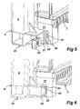
- a flexible metal clip 22 (shown in Fig. 5 before and in Fig. 6 after attachment) is used to interconnect the manifolds 8 and 11.
- each one of these manifolds 8 and 11 has a flange 23 and 24, respectively, the flanges 23, 24 abutting one another and lying in a plane parallel to the coolant radiator 3 and the charge air cooler 4.
- the flange 24, pertaining to the manifold 7, has a pin 25 extending into an oblong hole 26 in the opposite flange 23.
- the pin 25 and the oblong hole 26 serve to restrict mutual movement of the coolant radiator 3 and the charge air cooler 4 at the third corner 15 to movement only to and fro the rigid fastener 19 at the first corner 13, wherein friction between the flanges 23, 24 also helps counteracting degrading vibrations.
- the clip 22, together with the pin 25 and the oblong hole 26, defines a second two-way fastener controlling mutual manifold movement at the third corner 15.
- a flexible metal clip 27 (shown in Fig. 7 before and in Fig. 8 after attachment) is used to interconnect the manifolds 7 and 11. Again each one of these manifolds 7 and 11 has a flange 28 and 29, respectively, the flanges 28, 29 abutting one another and lying in a plane parallel to the coolant radiator 3 and the charge air cooler 4. Unlike the arrangement at the third corner 15, there is no extra movement restricting means at the fourth corner 16, however, friction between the flanges 28, 29 again helps counteracting degrading vibrations.
- the clip 27 defines a four-way fastener allowing mutual manifold movement at the fourth corner 16 to and fro both the first and second two-way fasteners, i.e. both vertically and horizontally in a plane parallel to the coolant radiator 3 and the charge air cooler 4.
- the referred embodiment described above can be altered in different ways in order to accomplish adaptation to a certain vehicle.
- the preferred embodiment comprising rigidly connecting the cold outlet manifold of the charge air cooler, which is exposed to the most prominent heat distortion, to the hot inlet manifold of the coolant radiator, which is less exposed to such distortion, at a top corner of the cooling module, is believed to be the most convenient one in view of vehicle assembly and long-time durability.
Abstract
Description
- The present invention relates to a cooling module, comprising a first heat exchanger having a first heat exchange core, which is placed between and communicates with a first pair of parallel supporting manifolds, and a second heat exchanger having a second heat exchange core, which is in back-to-front relationship with said first heat exchange core and which is placed between and communicates with a second pair of parallel supporting manifolds perpendicular to said first pair of supporting manifolds, wherein said first pair of supporting manifolds is fastened to said second pair of supporting manifolds at four heat exchanger corners by means of fasteners, the first one of said corners being located at a first end of a first manifold of said pair of first supporting manifolds, the second one of said corners being located at a second end of said first manifold, the third one of said corners being located at a first end of a second manifold of said pair of first supporting manifolds, and the fourth one of said corners being located at a second end of said second manifold and being diametrically opposed to the first corner, and wherein one of said pairs of supporting manifolds is adapted to support the cooling module on a motor vehicle frame.
- In vehicles having supercharged combustion engines a coolant radiator for cooling the engine and a charge air cooler for cooling the engine intake air are usually mounted in parallel in the vehicle front. Both the coolant radiator and the charge air cooler have an inlet tank or manifold and an outlet tank or manifold and each a tube package or heat exchange core between these manifolds. As the heat exchange cores are perpendicular to each other, the manifolds of the coolant radiator and the charge air cooler are perpendicular too. Thus, if the coolant radiator and the charge air cooler are of similar size, there are four corners where the manifolds overlap or are in close relation to one another. Interconnection of the manifolds at these corners, as stated by way of introduction, means creating a cooling module, which considerably facilitates vehicle assembly. A cooling module of that kind is known from
DE 100 18 001 C2 . - According to
DE 100 18 001 C2 the coolant radiator is vertically arranged with the inlet manifold on top and the outlet manifold at the bottom, whereas the charge air cooler is arranged horizontally with its manifolds in an upright vertical position. The upright manifolds have projecting arms at their ends making the charge air cooler fit the coolant radiator and enabling easy assembly of the two by means of fasteners. The bottom ones of these fasteners connect the downwardly extending arms in a rigid way with the coolant radiator and the top ones connect the upwardly extending arms with the coolant radiator in a floating way in order to compensate for either core's thermal expansion. - A first drawback of the prior art solution according to
DE 100 18 001 C1 is that the four extending arms on the cooler manifolds render the charge air cooler heavier as well as more complicated and expensive than an ordinary charge air cooler. A second drawback is that there are no means provided to compensate for thermal expansion at the downwardly extending arms with their rigid fasteners. This means that the integrity of either the charge air cooler or the bottom manifold of the coolant radiator is endangered when big differences in thermal expansion are at hand. A third drawback is that the floating mount of both the upwardly extending arms can lead to vibrations from the vehicle frame, to which the charge air cooler is bolted, making the coolant radiator top swing out of phase with the charge air cooler, which is detrimental to the long-time integrity of the cooling module due too fatigue problems. -
US 6 273 182 discloses a cooling module in accordance with the preamble of claim 1. - The object of the invention is to obviate the prior art drawbacks.
- According to the invention this is done by means of a cooling module as described by way of introduction, characterised by that a rigid fastener is provided at said first corner, that a first two-way fastener is provided at said second corner allowing mutual movement of the heat exchangers at said second corner only to and fro said rigid fastener, that a second two-way fastener is provided at said third corner allowing mutual movement of the heat exchangers at said third corner only to and fro said rigid fastener, and that a four-way fastener is provided at said fourth corner allowing mutual movement of the heat exchangers at said fourth corner to and fro said first two-way fastener and said second two-way fastener.
- By appropriate mutual sizing of both heat exchangers and direct interconnection of their manifolds by means of suitable fasteners, lighter and less complicated and thus less expensive heat exchangers can be used. Further, by using just one rigid fastener the problems with thermal expansion are obviated, because the remaining fasteners provide the necessary compensation. And by carefully designing the three non-rigid fasteners and giving them defined directions of work, the prior art vibration problems are at least mitigated, because the heat exchangers according to the invention always are forced to swing in phase.
- Preferably said rigid fastener is a bolt extending through sleeves in the manifolds at said first corner. This is obviously the most simple and assembly friendly solution, and yet a very reliable one.
- The first two-way fastener is preferably a bracket, attached to the manifolds at said second corner and having a flexing part between the attachment points at the manifolds. Such a bracket can be an easy to make sheet metal piece, said flexing part being a part thereof which is adapted to be bent in a limited extent to and fro the rigid fastener and yet capable of vertically supporting the weight of a heat exchanger without any yielding.
- The second two-way fastener is preferably a retainer clip extending over and holding together flanges on the manifolds at said third corner, wherein one of said flanges has a pin extending into a movement restricting oblong hole in the other flange. Furthermore, the four-way fastener is preferably too a retainer clip extending over and holding together flanges on the manifolds at said fourth corner. As the heat exchangers are adequately supported at two corners by the rigid fastener and the first two-way fastener, simple and easy to mount clips suffice at the remaining corners to join the heat exchangers in a safe way. However, the pin cooperating with the oblong hole at the third corner is vital, because of the necessity according to the invention to limit mutual movement of the heat exchangers at that corner.
- According to one embodiment the first heat exchanger is a coolant radiator with a hot inlet manifold and a cold outlet manifold and the second heat exchanger a charge air cooler with a hot inlet manifold and a cold outlet manifold, the first corner with the rigid fastener being the one common to both cold outlet manifolds. This embodiment is most suited for vehicles where the charge air cooler supports the coolant radiator from below, such that the top of the coolant radiator is free to expand upwards.
- According to another embodiment the first heat exchanger is a coolant radiator with a hot top inlet manifold and a cold bottom outlet manifold and the second heat exchanger a charge air cooler with a hot first side inlet manifold and a cold second side outlet manifold, the charge air cooler manifolds being adapted to support the cooling module on said motor vehicle frame, and said first corner with the rigid fastener being located at said cold second side outlet manifold. This embodiment is most suited for vehicles where the charge air cooler supports the coolant radiator in a hanging manner, such that the bottom part of the coolant radiator is free to expand downwards.
- It is obvious to the one skilled in the art that either pair of manifolds may be adapted to support the cooling module on said motor vehicle frame, and that, if one of the heat exchangers is a charge air cooler, the charge air cooler manifolds preferably are adapted to support the cooling module on said motor vehicle frame.
- A preferred embodiment of the invention is described in detail in below with reference to the drawings, in which identical reference numbers depict identical parts. In the drawings:
-
Fig. 1 is a front perspective view of a cooling module according to the invention; -
Fig. 2 is a rear perspective view of the cooling module; -
Fig. 3 is a top perspective view of a first corner of the cooling module; -
Fig. 4 is a top perspective view of a second corner of the cooling module; -
Figs. 5 and 6 are a bottom perspective views of a third corner of the cooling module prior to and after assembly; and -
Figs. 7 and 8 are bottom perspective views of a fourth corner of the cooling module prior to and after assembly. - In
Figs. 1 and 2 a preferred embodiment of a cooling module 1 is shown, adapted to be mounted on aframe 2 of a truck (not shown), which is driven by a supercharged diesel engine. The cooling module 1 comprises acoolant radiator 3 for cooling coolant heated by the diesel engine and acharge air cooler 4 for cooling supercharged air before the air is fed into the diesel engine. Thecharge air cooler 4 is mounted in front of and in parallel with thecoolant radiator 2 and supports the whole cooling on the truck frame by means of a pair ofanti-vibration mounts - The
anti-vibration mounts side inlet manifold 7 of thecharge air cooler 4 and a cold secondside outlet manifold 8 of thecharge air cooler 4, respectively, bothmanifolds manifolds core 9, which is tightly connected to bothmanifolds - The
coolant radiator 3 also has manifolds. These are however horizontally arranged and comprise an hottop inlet manifold 10 and a coldbottom outlet manifold 11. Again, between themanifolds core 12, which is tightly connected to bothmanifolds - As can be seen clearly in
Figs. 1 and 2 , the cooling module 1 defines four corners. The first one of these corners is depicted 13 and is located at a first end of the cold secondside outlet manifold 8 of thecharge air cooler 4 and a first end of the hottop inlet manifold 10 of thecoolant radiator 3, respectively, said ends overlapping one another. The second one of said corners is depicted 14 and is located at a first end of the hot firstside inlet manifold 7 of thecharge air cooler 4 and a second end of the hottop inlet manifold 10 of thecoolant radiator 3, respectively, said ends overlapping one another. The third one of said corners is depicted 15 and is located at a second end of the cold secondside outlet manifold 8 of thecharge air cooler 4 and a first end of the coldbottom outlet manifold 11 of thecoolant radiator 3, respectively, said ends overlapping one another. The fourth one of said corners is depicted 16 and is located at a second end of the hot firstside inlet manifold 7 of thecharge air cooler 4 and a second end of the coldbottom inlet manifold 11 of thecoolant radiator 3, respectively, said ends also overlapping one another. - At the
first corner 13, which is shown in detail inFig. 3 , eachmanifold own sleeve Fig. 2 ) extends, holding themanifolds - At the
second corner 14, which is shown in detail inFig. 4 , abracket 20 of sheet metal is attached to themanifolds second corner 14. Thebracket 20 has a flat central flexingpart 21 between the attachment points at themanifolds part 21 lying in a vertical plane perpendicular to thecoolant radiator 3 and thecharge air cooler 4. Thus thebracket 20 defines a first two-way fastener, allowing mutual movement of thecoolant radiator 3 and thecharge air cooler 4 at thesecond corner 14 only to and fro therigid fastener 19 at thefirst corner 13, wherein the inherent resistance to flexing ofpart 21 advantageously counteracts degrading vibrations. - At the
third corner 15, which is shown in detail inFigs. 5 and 6 , a flexible metal clip 22 (shown inFig. 5 before and inFig. 6 after attachment) is used to interconnect themanifolds manifolds flange flanges coolant radiator 3 and thecharge air cooler 4. Theflange 24, pertaining to themanifold 7, has apin 25 extending into anoblong hole 26 in theopposite flange 23. Thepin 25 and theoblong hole 26 serve to restrict mutual movement of thecoolant radiator 3 and thecharge air cooler 4 at thethird corner 15 to movement only to and fro therigid fastener 19 at thefirst corner 13, wherein friction between theflanges clip 22, together with thepin 25 and theoblong hole 26, defines a second two-way fastener controlling mutual manifold movement at thethird corner 15. - At the
fourth corner 16, which is shown in detail inFigs. 7 and 8 , a flexible metal clip 27 (shown inFig. 7 before and inFig. 8 after attachment) is used to interconnect themanifolds manifolds flange flanges coolant radiator 3 and thecharge air cooler 4. Unlike the arrangement at thethird corner 15, there is no extra movement restricting means at thefourth corner 16, however, friction between theflanges clip 27 defines a four-way fastener allowing mutual manifold movement at thefourth corner 16 to and fro both the first and second two-way fasteners, i.e. both vertically and horizontally in a plane parallel to thecoolant radiator 3 and thecharge air cooler 4.
It is obvious to the one skilled in the art that the referred embodiment described above can be altered in different ways in order to accomplish adaptation to a certain vehicle. However, at present the preferred embodiment, comprising rigidly connecting the cold outlet manifold of the charge air cooler, which is exposed to the most prominent heat distortion, to the hot inlet manifold of the coolant radiator, which is less exposed to such distortion, at a top corner of the cooling module, is believed to be the most convenient one in view of vehicle assembly and long-time durability.
Claims (9)
- A cooling module (1), comprising
a first heat exchanger (3) having a first heat exchange core (12), which is placed between and communicates with a first pair of parallel supporting manifolds (10, 11), and
a second heat exchanger (4) having a second heat exchange core (9), which is in back-to-front relationship with said first heat exchange core (12) and which is placed between and communicates with a second pair of parallel supporting manifolds (7, 8) perpendicular to said first pair of supporting manifolds (10, 11),
wherein said first pair of supporting manifolds (10, 11) is fastened to said second pair of supporting manifolds (7, 8) at four heat exchanger corners (13, 14, 15, 16) by means of fasteners,
the first one (13) of said corners being located at a first end of a first manifold (10) of said pair of first supporting manifolds (10, 11),
the second one (14) of said corners being located at a second end of said first manifold (10),
the third one (15) of said corners being located at a first end of a second manifold (11) of said pair of first supporting manifolds (10, 11), and
the fourth one (16) of said corners being located at a second end of said second manifold (11) and being diametrically opposed to the first corner (13), and
wherein one of said pairs of supporting manifolds (7, 8; 10, 11) is adapted to support the cooling module (1) on a motor vehicle frame (2),
characterised in
that a rigid fastener (19) is provided at said first corner (13),
that a first two-way fastener (20) is provided at said second corner (14) allowing mutual movement of the heat exchangers (3, 4) at said second corner (14) only to and fro said rigid fastener (19),
that a second two-way fastener (22) is provided at said third corner (15) allowing mutual movement of the heat exchangers (3, 4) at said third corner (15) only to and fro said rigid fastener (19), and
that a four-way fastener (27) is provided at said fourth corner (16) allowing mutual movement of the heat exchangers (3, 4) at said fourth corner (16) to and fro said first two-way fastener (20) and said second two-way fastener (22). - A cooling module according to claim 1, wherein said rigid fastener is a bolt (19) extending through sleeves (17, 18) in the manifolds (8, 10) at said first corner (13).
- A cooling module according to claim 1 or 2, wherein said first two-way fastener is a bracket (20), attached to the manifolds (7, 10) at said second corner (14) and having a flexing part (21) between the attachment points at the manifolds (7, 10).
- A cooling module according to any one of claims 1-3, wherein said second two-way fastener is a retainer clip (22) extending over and holding together flanges (23, 24) on the manifolds (8, 11) at said third corner (15), wherein one of said flanges (23) has a pin (25) extending into a movement restricting oblong hole (26) in the other flange (24).
- A cooling module according to any one of claims 1-4, wherein said four-way fastener is a retainer clip (27) extending over and holding together flanges (28, 29) on the manifolds (7, 11) at said fourth corner (16).
- A cooling module according to any one of claims 1-5, wherein said first heat exchanger is a coolant radiator (3) with a hot inlet manifold (10) and a cold outlet manifold (11) and said second heat exchanger is a charge air cooler (4) with a hot inlet manifold (7) and a cold outlet manifold (8), the first corner with the rigid fastener (19) being the one common to both cold outlet manifolds (8, 11).
- A cooling module according to any one of claims 1-5, wherein said first heat exchanger is a coolant radiator (3) with a hot top inlet manifold (10) and a cold bottom outlet manifold (11) and said second heat exchanger is a charge air cooler (4) with a hot first side inlet manifold (7) and a cold second side outlet manifold (8), the charge air cooler manifolds (7, 8) being adapted to support the cooling module (1) on said motor vehicle frame (2), and said first corner with the rigid fastener (19) being located at said cold second side outlet manifold (8).
- A cooling module according to any one of claims 1-7, wherein either pair of manifolds (7, 8; 10, 11) is adapted to support the cooling module (1) on said motor vehicle frame (2).
- A cooling module according to any one of claims 1-7, wherein one of the heat exchangers is a charge air cooler (4) and wherein the charge air cooler manifolds (7, 8) are adapted to support the cooling module (1) on said motor vehicle frame (2).
Applications Claiming Priority (1)
| Application Number | Priority Date | Filing Date | Title |
|---|---|---|---|
| SE0502621A SE0502621L (en) | 2005-11-30 | 2005-11-30 | Cooler Module |
Publications (2)
| Publication Number | Publication Date |
|---|---|
| EP1793191A1 EP1793191A1 (en) | 2007-06-06 |
| EP1793191B1 true EP1793191B1 (en) | 2009-07-22 |
Family
ID=37728140
Family Applications (1)
| Application Number | Title | Priority Date | Filing Date |
|---|---|---|---|
| EP06125175A Not-in-force EP1793191B1 (en) | 2005-11-30 | 2006-11-30 | Cooling module with heat exchangers in back-to-front relationship |
Country Status (5)
| Country | Link |
|---|---|
| US (1) | US7637309B2 (en) |
| EP (1) | EP1793191B1 (en) |
| AT (1) | ATE437348T1 (en) |
| DE (1) | DE602006007935D1 (en) |
| SE (1) | SE0502621L (en) |
Cited By (1)
| Publication number | Priority date | Publication date | Assignee | Title |
|---|---|---|---|---|
| EP2392883A2 (en) | 2010-06-04 | 2011-12-07 | Behr GmbH & Co. KG | Coolant cooler |
Families Citing this family (23)
| Publication number | Priority date | Publication date | Assignee | Title |
|---|---|---|---|---|
| US7287574B2 (en) * | 2002-02-11 | 2007-10-30 | Valeo, Inc. | Attachment and articles using same |
| DE10322211A1 (en) * | 2003-05-16 | 2004-12-02 | Modine Manufacturing Co., Racine | heat exchanger block |
| DE102005039090A1 (en) * | 2005-08-06 | 2007-02-08 | Behr Gmbh & Co. Kg | Assembly support system |
| DE102005062297A1 (en) * | 2005-12-24 | 2007-07-05 | Dr.Ing.H.C. F. Porsche Ag | Heat transfer unit |
| JP2007308131A (en) * | 2006-04-20 | 2007-11-29 | Denso Corp | Heat exchanger for motorcycle |
| DE102007007232A1 (en) * | 2007-02-14 | 2008-08-21 | Behr Gmbh & Co. Kg | Device for attaching an additional part, in particular a fan cover to a heat exchanger |
| DE102007033116A1 (en) * | 2007-07-13 | 2009-01-15 | Behr Gmbh & Co. Kg | Front end module for vehicles |
| JP4658157B2 (en) * | 2008-04-28 | 2011-03-23 | 豊田鉄工株式会社 | Vehicle cooling component support device |
| USD619511S1 (en) * | 2009-12-23 | 2010-07-13 | Michael Sullivan | Radiator |
| US9309839B2 (en) | 2010-03-18 | 2016-04-12 | Modine Manufacturing Company | Heat exchanger and method of manufacturing the same |
| AU2011201083B2 (en) | 2010-03-18 | 2013-12-05 | Modine Manufacturing Company | Heat exchanger and method of manufacturing the same |
| WO2012135956A1 (en) * | 2011-04-07 | 2012-10-11 | Dana Canada Corporation | Heat exchanger with resiliently mounted bracket |
| US9134080B2 (en) | 2012-01-10 | 2015-09-15 | U.S. Farathane Corporation | Reconfigurable front and upper one piece baffles for directing incoming air from a vehicle front fascia to a radiator cooling module |
| US20130255913A1 (en) * | 2012-03-30 | 2013-10-03 | Thermo King Corporation | Transport refrigeration system |
| FR2990655B1 (en) * | 2012-05-16 | 2014-05-23 | Peugeot Citroen Automobiles Sa | COOLING DEVICE FOR A MOTOR-PROPELLER GROUP OF A HYBRID VEHICLE, WITH RADIATORS AND SOLIDARIZATION MEANS ADAPTED TO BEAM DILATIONS |
| US20140125070A1 (en) * | 2012-11-08 | 2014-05-08 | Caterpillar Sarl | Cooling package latch mechanism |
| DE112015002074T5 (en) * | 2014-04-29 | 2017-02-23 | Dana Canada Corporation | Intercooler with multipart plastic housing |
| GB2525932B (en) * | 2014-05-09 | 2019-06-26 | Calsonic Kansei Uk Ltd | A mounting assembly for an automotive thermal system |
| USD717218S1 (en) * | 2014-07-24 | 2014-11-11 | Resource Intl, Inc. | Automotive radiator |
| KR102026103B1 (en) * | 2014-09-05 | 2019-09-27 | 한온시스템 주식회사 | Cooling module |
| USD746732S1 (en) * | 2015-09-04 | 2016-01-05 | Randall Industries, Inc. | Bolt-on radiator |
| USD751472S1 (en) * | 2015-09-08 | 2016-03-15 | Randall Industries, Inc. | Bolt-on radiator |
| US10145294B2 (en) * | 2015-11-23 | 2018-12-04 | Ford Global Technologies, Llc | Charge air cooler shroud mounting system with one fixed and three floating attachment points |
Family Cites Families (13)
| Publication number | Priority date | Publication date | Assignee | Title |
|---|---|---|---|---|
| US4651816A (en) * | 1986-03-19 | 1987-03-24 | Modine Manufacturing Company | Heat exchanger module for a vehicle or the like |
| JP3191385B2 (en) * | 1991-07-12 | 2001-07-23 | 株式会社デンソー | Condenser mounting device |
| FR2739598B1 (en) * | 1995-10-06 | 1997-12-05 | Valeo Thermique Moteur Sa | DEVICE FOR ATTACHING A HIGH TEMPERATURE HEAT EXCHANGER |
| GB9609440D0 (en) * | 1996-05-04 | 1996-07-10 | Ford Motor Co | Radiator and condenser assembly |
| JPH11148794A (en) * | 1997-11-14 | 1999-06-02 | Zexel:Kk | Heat exchanger |
| FR2779220B1 (en) * | 1998-05-28 | 2000-12-15 | Valeo Thermique Moteur Sa | HEAT EXCHANGER ASSEMBLY FOR A MOTOR VEHICLE |
| DE19909672B4 (en) * | 1999-03-05 | 2005-06-02 | Behr Gmbh & Co. Kg | cooling module |
| DE10018001C2 (en) | 2000-04-11 | 2003-07-17 | Behr Gmbh & Co | Cooler module for an internal combustion engine |
| US6273182B1 (en) * | 2000-05-19 | 2001-08-14 | Delphi Technologies, Inc. | Heat exchanger mounting |
| US6510891B2 (en) * | 2001-04-27 | 2003-01-28 | Delphi Technologies, Inc. | Clip-retainer for heat exchanger |
| US6513579B1 (en) * | 2001-09-27 | 2003-02-04 | Delphi Technologies, Inc. | Post braze heat exchanger mounting and support brackets |
| FR2841973B1 (en) * | 2002-07-05 | 2004-10-01 | Valeo Thermique Moteur Sa | HEAT EXCHANGER SUPPORT DEVICE AND ASSOCIATED HEAT EXCHANGE MODULE |
| JP2005188799A (en) * | 2003-12-25 | 2005-07-14 | Denso Corp | Heat exchanger for vehicle |
-
2005
- 2005-11-30 SE SE0502621A patent/SE0502621L/en not_active IP Right Cessation
-
2006
- 2006-11-09 US US11/595,648 patent/US7637309B2/en not_active Expired - Fee Related
- 2006-11-30 DE DE602006007935T patent/DE602006007935D1/en active Active
- 2006-11-30 EP EP06125175A patent/EP1793191B1/en not_active Not-in-force
- 2006-11-30 AT AT06125175T patent/ATE437348T1/en not_active IP Right Cessation
Cited By (2)
| Publication number | Priority date | Publication date | Assignee | Title |
|---|---|---|---|---|
| EP2392883A2 (en) | 2010-06-04 | 2011-12-07 | Behr GmbH & Co. KG | Coolant cooler |
| DE102010029698A1 (en) | 2010-06-04 | 2011-12-08 | Behr Gmbh & Co. Kg | Coolant radiator |
Also Published As
| Publication number | Publication date |
|---|---|
| US7637309B2 (en) | 2009-12-29 |
| US20070119564A1 (en) | 2007-05-31 |
| SE528791C2 (en) | 2007-02-13 |
| SE0502621L (en) | 2007-02-13 |
| EP1793191A1 (en) | 2007-06-06 |
| ATE437348T1 (en) | 2009-08-15 |
| DE602006007935D1 (en) | 2009-09-03 |
Similar Documents
| Publication | Publication Date | Title |
|---|---|---|
| EP1793191B1 (en) | Cooling module with heat exchangers in back-to-front relationship | |
| US4938284A (en) | Heat exchanger | |
| US4540044A (en) | Radiator arrangement | |
| US8671919B2 (en) | Intake device of engine | |
| US5046554A (en) | Cooling module | |
| KR102089827B1 (en) | Work vehicle | |
| US5566748A (en) | Charge air cooler/condenser sub-assembly for use in a motor vehicle | |
| JPH09500710A (en) | Heat exchanger | |
| US20090260787A1 (en) | Heat exchanger for motor vehicles | |
| US6386273B1 (en) | Heat exchanger assemblies for vehicles | |
| ZA200602983B (en) | Arrangement for securing a heat exchanger to another heat exchanger | |
| US20010013405A1 (en) | Heat exchanger assembly | |
| US8752522B1 (en) | Compact multi-unit vehicle cooling system | |
| US11230968B2 (en) | Frameless cooling module | |
| US20110240252A1 (en) | Engine-mountable cooling system | |
| US10018101B2 (en) | Cooling system and a method for its use | |
| US20050006052A1 (en) | Vibration-resistant mounting bracket for heat exchangers | |
| JP2011038467A (en) | Exhaust gas recirculating device of engine | |
| US20070051494A1 (en) | Cooling module and elastic bearing therefor | |
| CA3203590A1 (en) | Heat exchanger module | |
| JP3980163B2 (en) | Heat exchanger | |
| CN201685695U (en) | Automobile cooling system | |
| JP4043093B2 (en) | Heat exchanger | |
| EP1867943B1 (en) | Heat exchange module for vehicles | |
| JP2000282959A (en) | Egr device |
Legal Events
| Date | Code | Title | Description |
|---|---|---|---|
| PUAI | Public reference made under article 153(3) epc to a published international application that has entered the european phase |
Free format text: ORIGINAL CODE: 0009012 |
|
| AK | Designated contracting states |
Kind code of ref document: A1 Designated state(s): AT BE BG CH CY CZ DE DK EE ES FI FR GB GR HU IE IS IT LI LT LU LV MC NL PL PT RO SE SI SK TR |
|
| AX | Request for extension of the european patent |
Extension state: AL BA HR MK YU |
|
| 17P | Request for examination filed |
Effective date: 20071030 |
|
| AKX | Designation fees paid |
Designated state(s): AT BE BG CH CY CZ DE DK EE ES FI FR GB GR HU IE IS IT LI LT LU LV MC NL PL PT RO SE SI SK TR |
|
| GRAP | Despatch of communication of intention to grant a patent |
Free format text: ORIGINAL CODE: EPIDOSNIGR1 |
|
| GRAS | Grant fee paid |
Free format text: ORIGINAL CODE: EPIDOSNIGR3 |
|
| GRAA | (expected) grant |
Free format text: ORIGINAL CODE: 0009210 |
|
| RAP1 | Party data changed (applicant data changed or rights of an application transferred) |
Owner name: TITANX ENGINE COOLING HOLDING AB |
|
| AK | Designated contracting states |
Kind code of ref document: B1 Designated state(s): AT BE BG CH CY CZ DE DK EE ES FI FR GB GR HU IE IS IT LI LT LU LV MC NL PL PT RO SE SI SK TR |
|
| REG | Reference to a national code |
Ref country code: GB Ref legal event code: FG4D |
|
| REG | Reference to a national code |
Ref country code: CH Ref legal event code: EP |
|
| REG | Reference to a national code |
Ref country code: IE Ref legal event code: FG4D |
|
| REF | Corresponds to: |
Ref document number: 602006007935 Country of ref document: DE Date of ref document: 20090903 Kind code of ref document: P |
|
| PG25 | Lapsed in a contracting state [announced via postgrant information from national office to epo] |
Ref country code: AT Free format text: LAPSE BECAUSE OF FAILURE TO SUBMIT A TRANSLATION OF THE DESCRIPTION OR TO PAY THE FEE WITHIN THE PRESCRIBED TIME-LIMIT Effective date: 20090722 Ref country code: LT Free format text: LAPSE BECAUSE OF FAILURE TO SUBMIT A TRANSLATION OF THE DESCRIPTION OR TO PAY THE FEE WITHIN THE PRESCRIBED TIME-LIMIT Effective date: 20090722 Ref country code: FI Free format text: LAPSE BECAUSE OF FAILURE TO SUBMIT A TRANSLATION OF THE DESCRIPTION OR TO PAY THE FEE WITHIN THE PRESCRIBED TIME-LIMIT Effective date: 20090722 Ref country code: ES Free format text: LAPSE BECAUSE OF FAILURE TO SUBMIT A TRANSLATION OF THE DESCRIPTION OR TO PAY THE FEE WITHIN THE PRESCRIBED TIME-LIMIT Effective date: 20091102 Ref country code: SE Free format text: LAPSE BECAUSE OF FAILURE TO SUBMIT A TRANSLATION OF THE DESCRIPTION OR TO PAY THE FEE WITHIN THE PRESCRIBED TIME-LIMIT Effective date: 20090722 Ref country code: IS Free format text: LAPSE BECAUSE OF FAILURE TO SUBMIT A TRANSLATION OF THE DESCRIPTION OR TO PAY THE FEE WITHIN THE PRESCRIBED TIME-LIMIT Effective date: 20091122 |
|
| PG25 | Lapsed in a contracting state [announced via postgrant information from national office to epo] |
Ref country code: LV Free format text: LAPSE BECAUSE OF FAILURE TO SUBMIT A TRANSLATION OF THE DESCRIPTION OR TO PAY THE FEE WITHIN THE PRESCRIBED TIME-LIMIT Effective date: 20090722 Ref country code: PL Free format text: LAPSE BECAUSE OF FAILURE TO SUBMIT A TRANSLATION OF THE DESCRIPTION OR TO PAY THE FEE WITHIN THE PRESCRIBED TIME-LIMIT Effective date: 20090722 Ref country code: SI Free format text: LAPSE BECAUSE OF FAILURE TO SUBMIT A TRANSLATION OF THE DESCRIPTION OR TO PAY THE FEE WITHIN THE PRESCRIBED TIME-LIMIT Effective date: 20090722 |
|
| PG25 | Lapsed in a contracting state [announced via postgrant information from national office to epo] |
Ref country code: BG Free format text: LAPSE BECAUSE OF FAILURE TO SUBMIT A TRANSLATION OF THE DESCRIPTION OR TO PAY THE FEE WITHIN THE PRESCRIBED TIME-LIMIT Effective date: 20091022 Ref country code: PT Free format text: LAPSE BECAUSE OF FAILURE TO SUBMIT A TRANSLATION OF THE DESCRIPTION OR TO PAY THE FEE WITHIN THE PRESCRIBED TIME-LIMIT Effective date: 20091122 |
|
| PG25 | Lapsed in a contracting state [announced via postgrant information from national office to epo] |
Ref country code: RO Free format text: LAPSE BECAUSE OF FAILURE TO SUBMIT A TRANSLATION OF THE DESCRIPTION OR TO PAY THE FEE WITHIN THE PRESCRIBED TIME-LIMIT Effective date: 20090722 Ref country code: EE Free format text: LAPSE BECAUSE OF FAILURE TO SUBMIT A TRANSLATION OF THE DESCRIPTION OR TO PAY THE FEE WITHIN THE PRESCRIBED TIME-LIMIT Effective date: 20090722 Ref country code: CZ Free format text: LAPSE BECAUSE OF FAILURE TO SUBMIT A TRANSLATION OF THE DESCRIPTION OR TO PAY THE FEE WITHIN THE PRESCRIBED TIME-LIMIT Effective date: 20090722 Ref country code: DK Free format text: LAPSE BECAUSE OF FAILURE TO SUBMIT A TRANSLATION OF THE DESCRIPTION OR TO PAY THE FEE WITHIN THE PRESCRIBED TIME-LIMIT Effective date: 20090722 |
|
| PLBE | No opposition filed within time limit |
Free format text: ORIGINAL CODE: 0009261 |
|
| STAA | Information on the status of an ep patent application or granted ep patent |
Free format text: STATUS: NO OPPOSITION FILED WITHIN TIME LIMIT |
|
| PG25 | Lapsed in a contracting state [announced via postgrant information from national office to epo] |
Ref country code: SK Free format text: LAPSE BECAUSE OF FAILURE TO SUBMIT A TRANSLATION OF THE DESCRIPTION OR TO PAY THE FEE WITHIN THE PRESCRIBED TIME-LIMIT Effective date: 20090722 Ref country code: BE Free format text: LAPSE BECAUSE OF FAILURE TO SUBMIT A TRANSLATION OF THE DESCRIPTION OR TO PAY THE FEE WITHIN THE PRESCRIBED TIME-LIMIT Effective date: 20090722 |
|
| 26N | No opposition filed |
Effective date: 20100423 |
|
| PG25 | Lapsed in a contracting state [announced via postgrant information from national office to epo] |
Ref country code: MC Free format text: LAPSE BECAUSE OF NON-PAYMENT OF DUE FEES Effective date: 20091130 |
|
| PG25 | Lapsed in a contracting state [announced via postgrant information from national office to epo] |
Ref country code: GR Free format text: LAPSE BECAUSE OF FAILURE TO SUBMIT A TRANSLATION OF THE DESCRIPTION OR TO PAY THE FEE WITHIN THE PRESCRIBED TIME-LIMIT Effective date: 20091023 Ref country code: IE Free format text: LAPSE BECAUSE OF NON-PAYMENT OF DUE FEES Effective date: 20091130 |
|
| PG25 | Lapsed in a contracting state [announced via postgrant information from national office to epo] |
Ref country code: LU Free format text: LAPSE BECAUSE OF NON-PAYMENT OF DUE FEES Effective date: 20091130 |
|
| PG25 | Lapsed in a contracting state [announced via postgrant information from national office to epo] |
Ref country code: HU Free format text: LAPSE BECAUSE OF FAILURE TO SUBMIT A TRANSLATION OF THE DESCRIPTION OR TO PAY THE FEE WITHIN THE PRESCRIBED TIME-LIMIT Effective date: 20100123 |
|
| REG | Reference to a national code |
Ref country code: CH Ref legal event code: PL |
|
| PG25 | Lapsed in a contracting state [announced via postgrant information from national office to epo] |
Ref country code: CH Free format text: LAPSE BECAUSE OF NON-PAYMENT OF DUE FEES Effective date: 20101130 Ref country code: LI Free format text: LAPSE BECAUSE OF NON-PAYMENT OF DUE FEES Effective date: 20101130 |
|
| PG25 | Lapsed in a contracting state [announced via postgrant information from national office to epo] |
Ref country code: TR Free format text: LAPSE BECAUSE OF FAILURE TO SUBMIT A TRANSLATION OF THE DESCRIPTION OR TO PAY THE FEE WITHIN THE PRESCRIBED TIME-LIMIT Effective date: 20090722 |
|
| PG25 | Lapsed in a contracting state [announced via postgrant information from national office to epo] |
Ref country code: CY Free format text: LAPSE BECAUSE OF FAILURE TO SUBMIT A TRANSLATION OF THE DESCRIPTION OR TO PAY THE FEE WITHIN THE PRESCRIBED TIME-LIMIT Effective date: 20090722 |
|
| REG | Reference to a national code |
Ref country code: FR Ref legal event code: PLFP Year of fee payment: 10 |
|
| REG | Reference to a national code |
Ref country code: FR Ref legal event code: PLFP Year of fee payment: 11 |
|
| REG | Reference to a national code |
Ref country code: FR Ref legal event code: PLFP Year of fee payment: 12 |
|
| REG | Reference to a national code |
Ref country code: FR Ref legal event code: PLFP Year of fee payment: 13 |
|
| REG | Reference to a national code |
Ref country code: GB Ref legal event code: 732E Free format text: REGISTERED BETWEEN 20191212 AND 20191218 |
|
| PGFP | Annual fee paid to national office [announced via postgrant information from national office to epo] |
Ref country code: NL Payment date: 20191119 Year of fee payment: 14 Ref country code: DE Payment date: 20191017 Year of fee payment: 14 |
|
| REG | Reference to a national code |
Ref country code: DE Ref legal event code: R081 Ref document number: 602006007935 Country of ref document: DE Owner name: TITANX HOLDING AB, SE Free format text: FORMER OWNER: TITANX ENGINE COOLING HOLDING AB, SOELVESBORG, SE |
|
| PGFP | Annual fee paid to national office [announced via postgrant information from national office to epo] |
Ref country code: FR Payment date: 20191017 Year of fee payment: 14 Ref country code: IT Payment date: 20191022 Year of fee payment: 14 |
|
| PGFP | Annual fee paid to national office [announced via postgrant information from national office to epo] |
Ref country code: GB Payment date: 20191017 Year of fee payment: 14 |
|
| REG | Reference to a national code |
Ref country code: DE Ref legal event code: R119 Ref document number: 602006007935 Country of ref document: DE |
|
| REG | Reference to a national code |
Ref country code: NL Ref legal event code: MM Effective date: 20201201 |
|
| GBPC | Gb: european patent ceased through non-payment of renewal fee |
Effective date: 20201130 |
|
| PG25 | Lapsed in a contracting state [announced via postgrant information from national office to epo] |
Ref country code: NL Free format text: LAPSE BECAUSE OF NON-PAYMENT OF DUE FEES Effective date: 20201201 |
|
| PG25 | Lapsed in a contracting state [announced via postgrant information from national office to epo] |
Ref country code: IT Free format text: LAPSE BECAUSE OF NON-PAYMENT OF DUE FEES Effective date: 20201130 Ref country code: FR Free format text: LAPSE BECAUSE OF NON-PAYMENT OF DUE FEES Effective date: 20201130 |
|
| PG25 | Lapsed in a contracting state [announced via postgrant information from national office to epo] |
Ref country code: GB Free format text: LAPSE BECAUSE OF NON-PAYMENT OF DUE FEES Effective date: 20201130 Ref country code: DE Free format text: LAPSE BECAUSE OF NON-PAYMENT OF DUE FEES Effective date: 20210601 |