EP1793179A1 - Multi-type air conditioner - Google Patents
Multi-type air conditioner Download PDFInfo
- Publication number
- EP1793179A1 EP1793179A1 EP05765138A EP05765138A EP1793179A1 EP 1793179 A1 EP1793179 A1 EP 1793179A1 EP 05765138 A EP05765138 A EP 05765138A EP 05765138 A EP05765138 A EP 05765138A EP 1793179 A1 EP1793179 A1 EP 1793179A1
- Authority
- EP
- European Patent Office
- Prior art keywords
- outdoor
- indoor
- heat exchanger
- outdoor heat
- pipe
- Prior art date
- Legal status (The legal status is an assumption and is not a legal conclusion. Google has not performed a legal analysis and makes no representation as to the accuracy of the status listed.)
- Granted
Links
Images


Classifications
-
- F—MECHANICAL ENGINEERING; LIGHTING; HEATING; WEAPONS; BLASTING
- F24—HEATING; RANGES; VENTILATING
- F24F—AIR-CONDITIONING; AIR-HUMIDIFICATION; VENTILATION; USE OF AIR CURRENTS FOR SCREENING
- F24F1/00—Room units for air-conditioning, e.g. separate or self-contained units or units receiving primary air from a central station
- F24F1/06—Separate outdoor units, e.g. outdoor unit to be linked to a separate room comprising a compressor and a heat exchanger
- F24F1/46—Component arrangements in separate outdoor units
- F24F1/48—Component arrangements in separate outdoor units characterised by air airflow, e.g. inlet or outlet airflow
- F24F1/50—Component arrangements in separate outdoor units characterised by air airflow, e.g. inlet or outlet airflow with outlet air in upward direction
-
- F—MECHANICAL ENGINEERING; LIGHTING; HEATING; WEAPONS; BLASTING
- F24—HEATING; RANGES; VENTILATING
- F24F—AIR-CONDITIONING; AIR-HUMIDIFICATION; VENTILATION; USE OF AIR CURRENTS FOR SCREENING
- F24F1/00—Room units for air-conditioning, e.g. separate or self-contained units or units receiving primary air from a central station
- F24F1/06—Separate outdoor units, e.g. outdoor unit to be linked to a separate room comprising a compressor and a heat exchanger
- F24F1/38—Fan details of outdoor units, e.g. bell-mouth shaped inlets or fan mountings
-
- F—MECHANICAL ENGINEERING; LIGHTING; HEATING; WEAPONS; BLASTING
- F25—REFRIGERATION OR COOLING; COMBINED HEATING AND REFRIGERATION SYSTEMS; HEAT PUMP SYSTEMS; MANUFACTURE OR STORAGE OF ICE; LIQUEFACTION SOLIDIFICATION OF GASES
- F25B—REFRIGERATION MACHINES, PLANTS OR SYSTEMS; COMBINED HEATING AND REFRIGERATION SYSTEMS; HEAT PUMP SYSTEMS
- F25B13/00—Compression machines, plants or systems, with reversible cycle
-
- F—MECHANICAL ENGINEERING; LIGHTING; HEATING; WEAPONS; BLASTING
- F25—REFRIGERATION OR COOLING; COMBINED HEATING AND REFRIGERATION SYSTEMS; HEAT PUMP SYSTEMS; MANUFACTURE OR STORAGE OF ICE; LIQUEFACTION SOLIDIFICATION OF GASES
- F25B—REFRIGERATION MACHINES, PLANTS OR SYSTEMS; COMBINED HEATING AND REFRIGERATION SYSTEMS; HEAT PUMP SYSTEMS
- F25B2313/00—Compression machines, plants or systems with reversible cycle not otherwise provided for
- F25B2313/007—Compression machines, plants or systems with reversible cycle not otherwise provided for three pipes connecting the outdoor side to the indoor side with multiple indoor units
-
- F—MECHANICAL ENGINEERING; LIGHTING; HEATING; WEAPONS; BLASTING
- F25—REFRIGERATION OR COOLING; COMBINED HEATING AND REFRIGERATION SYSTEMS; HEAT PUMP SYSTEMS; MANUFACTURE OR STORAGE OF ICE; LIQUEFACTION SOLIDIFICATION OF GASES
- F25B—REFRIGERATION MACHINES, PLANTS OR SYSTEMS; COMBINED HEATING AND REFRIGERATION SYSTEMS; HEAT PUMP SYSTEMS
- F25B2313/00—Compression machines, plants or systems with reversible cycle not otherwise provided for
- F25B2313/023—Compression machines, plants or systems with reversible cycle not otherwise provided for using multiple indoor units
- F25B2313/0231—Compression machines, plants or systems with reversible cycle not otherwise provided for using multiple indoor units with simultaneous cooling and heating
-
- F—MECHANICAL ENGINEERING; LIGHTING; HEATING; WEAPONS; BLASTING
- F25—REFRIGERATION OR COOLING; COMBINED HEATING AND REFRIGERATION SYSTEMS; HEAT PUMP SYSTEMS; MANUFACTURE OR STORAGE OF ICE; LIQUEFACTION SOLIDIFICATION OF GASES
- F25B—REFRIGERATION MACHINES, PLANTS OR SYSTEMS; COMBINED HEATING AND REFRIGERATION SYSTEMS; HEAT PUMP SYSTEMS
- F25B2313/00—Compression machines, plants or systems with reversible cycle not otherwise provided for
- F25B2313/025—Compression machines, plants or systems with reversible cycle not otherwise provided for using multiple outdoor units
- F25B2313/0253—Compression machines, plants or systems with reversible cycle not otherwise provided for using multiple outdoor units in parallel arrangements
-
- F—MECHANICAL ENGINEERING; LIGHTING; HEATING; WEAPONS; BLASTING
- F25—REFRIGERATION OR COOLING; COMBINED HEATING AND REFRIGERATION SYSTEMS; HEAT PUMP SYSTEMS; MANUFACTURE OR STORAGE OF ICE; LIQUEFACTION SOLIDIFICATION OF GASES
- F25B—REFRIGERATION MACHINES, PLANTS OR SYSTEMS; COMBINED HEATING AND REFRIGERATION SYSTEMS; HEAT PUMP SYSTEMS
- F25B2400/00—Component parts or details not otherwise provided for in this subclass
- F25B2400/07—Details of compressors or related parts
- F25B2400/075—Details of compressors or related parts with parallel compressors
-
- F—MECHANICAL ENGINEERING; LIGHTING; HEATING; WEAPONS; BLASTING
- F25—REFRIGERATION OR COOLING; COMBINED HEATING AND REFRIGERATION SYSTEMS; HEAT PUMP SYSTEMS; MANUFACTURE OR STORAGE OF ICE; LIQUEFACTION SOLIDIFICATION OF GASES
- F25B—REFRIGERATION MACHINES, PLANTS OR SYSTEMS; COMBINED HEATING AND REFRIGERATION SYSTEMS; HEAT PUMP SYSTEMS
- F25B2600/00—Control issues
- F25B2600/02—Compressor control
- F25B2600/021—Inverters therefor
-
- Y—GENERAL TAGGING OF NEW TECHNOLOGICAL DEVELOPMENTS; GENERAL TAGGING OF CROSS-SECTIONAL TECHNOLOGIES SPANNING OVER SEVERAL SECTIONS OF THE IPC; TECHNICAL SUBJECTS COVERED BY FORMER USPC CROSS-REFERENCE ART COLLECTIONS [XRACs] AND DIGESTS
- Y02—TECHNOLOGIES OR APPLICATIONS FOR MITIGATION OR ADAPTATION AGAINST CLIMATE CHANGE
- Y02B—CLIMATE CHANGE MITIGATION TECHNOLOGIES RELATED TO BUILDINGS, e.g. HOUSING, HOUSE APPLIANCES OR RELATED END-USER APPLICATIONS
- Y02B30/00—Energy efficient heating, ventilation or air conditioning [HVAC]
- Y02B30/70—Efficient control or regulation technologies, e.g. for control of refrigerant flow, motor or heating
Definitions
- the present invention relates to a multi-type air conditioner having a plurality of indoor units, and, more particularly, to a multi-type air conditioner which allows the indoor units to carry out cooling and heating operations at the same time.
- the multi-type air conditioner can carry out overall cooling operation, in which all the indoor units can carry out cooling, overall heating operation, in which all the indoor units carry out heating, and carry out simultaneous cooling/heating operation.
- the simultaneous cooling/heating operation includes mainly cooling operation having a large cooling capacity and mainly heating operation having a large heating capacity according to a difference of capacity between a cooling capacity and a heating capacity required by indoor side.
- a multi-type air conditioner Since it is necessary for such multi-type air conditioner to carry out the simultaneous cooling/heating operation as described above in various operating conditions, in a known a multi-type air conditioner, a plurality of outdoor heat exchangers are disposed in outdoor units and the number of heat exchangers and the capacities thereof to be used are switched depending on the operating conditions.
- Japanese Unexamined Patent Application Publication No. 5-332637 discloses a multi-type air conditioner which is provided with large and small outdoor heat exchangers having a different heat exchange capacity, and when an outdoor heat exchanger is used as a condenser in simultaneous cooling/heating operation, a refrigerant is supplied to the small capacity outdoor heat exchanger at all times. Further, in an outdoor unit, the small capacity outdoor heat exchanger is disposed on the large capacity outdoor heat exchanger, and an outdoor blower is disposed in an upper portion of the outdoor unit at a position near to the small capacity outdoor heat exchanger.
- the present invention was conceived in consideration of the above circumstances and an object of the present invention is to provide a multi-type air conditioner which can prevent reduction of a heating capacity in simultaneous cooling/heating operation even if an outside temperature is low.
- a multi-type air conditioner provided for achieving the above object comprises:
- the outdoor unit includes an outdoor blower blowing out air upward, the outdoor blower is disposed above the first outdoor heat exchanger, and the second outdoor heat exchanger is disposed below the first outdoor heat exchanger.
- the second outdoor heat exchanger has a capacity of 15% to 30% with respect to a capacity of the first outdoor heat exchanger.
- the multi-type air conditioner of the present invention having the characteristic features described above, even if an outside temperature is low, deterioration of a heating capacity can be prevented by keeping condensation pressure and the overall heating operation, the overall cooling operation, and the simultaneous cooling/heating operation can be carried out in modes in which the plurality of indoor units are controlled.
- a multi-type air conditioner according to the present invention is composed of an outdoor unit 1 and a plurality of indoor units 2.
- the outdoor unit 1 is connected to the plurality of indoor units 2 by a main pipe 3, which is composed of a liquid pipe 3a, a gas ejection pipe 3b, and a gas suction pipe 3c, through switching units 4 for switching operations of the indoor units 2 to heating or cooling.
- four sets of the indoor units 2a, 2b, 2c, and 2d are connected to corresponding four sets of the switching units 4a, 4b, 4c, and 4d, respectively.
- the outdoor unit 1 accommodates two sets of capacity variable compressors 5a and 5b, an oil separator 7, a four-way valve 8, a first outdoor heat exchanger 9a, a second outdoor heat exchanger 9b, a first outdoor expansion valve 10a, a second outdoor expansion valve 10b, a refrigerant amount adjustment tank 12, a gas-liquid separator 14, an outdoor blower 15, and an outdoor electric parts box 21, and the like.
- the outdoor electric parts box 21 accommodates an outdoor controller A and inverters for controlling the outdoor blower 15 and the compressor 5a, 5b, respectively and the like.
- the indoor units 2 accommodate indoor heat exchangers 16, indoor expansion valves 17, indoor blowers 18, and an indoor controller B.
- the switching units 4 accommodate liquid pipe connection pipes 41 for connecting the liquid pipe 3 to the liquid sides of the indoor heat exchangers 16, gas side connection pipes 42 for selectively connecting the gas ejection pipe 3b and the gas suction pipe 3c to the gas sides of the indoor heat exchangers 16, electromagnetic valves 43a, 43b, and a switching unit controller C.
- the inverters for driving the compressor 5a, 5b and the outdoor blower 15, the four-way valve 8, the first outdoor expansion valve 10a, the second outdoor expansion valve 10b, and an electromagnetic valve 11 are connected to the outdoor controller A.
- the indoor expansion valves 17 and the indoor blowers 18 are also connected to the indoor controller B.
- electromagnetic valves 43a, 43b are connected to the stitching unit controller C.
- the outdoor controller A determines opening and/or closing operation and degrees of openings of the various, valves in accordance with the inputs from various sensors (not shown) such as temperature sensors, pressure sensors, and the like disposed to the outdoor unit 1 and the indoor units 2 and also in accordance with the inputs from remote controllers RC connected to the indoor units 2, thereby controlling the various valves through the indoor controller B and the switching unit controller C.
- the outdoor unit 1 has a horizontal partition plate 22 disposed in an approximately intermediate portion in a vertical direction, and the inside of the outdoor unit 1 is vertically partitioned by the horizontal partition plate 22.
- An upper compartment on the horizontal partition plate 22 is arranged as a heat exchange chamber 23, and a lower compartment under it is arranged as a machine chamber 24.
- the outer periphery of the heat exchange chamber 23 and the machine chamber 24 is surrounded by a plurality of side panels 25 which form an outer peripheral wall, and the upper surface of the heat exchange chamber 23 is closed by a top plate 26 having a cylindrical blow-out port 28.
- a bottom plate 27 is disposed to the bottom of the machine chamber 24, and the compressors 5a, 5b, the gas/liquid separator 14, the electromagnetic valve 11, and a refrigerant pipe for connecting them, the outdoor electric parts box 21, and the like are disposed on the bottom plate 27.
- the first and second outdoor heat exchangers 9a, 9b are disposed in the heat exchange chamber 23 so as to face side surfaces thereof, and the second outdoor heat exchangers 9b are disposed to the lower portions of the first outdoor heat exchangers 9a on the upstream side thereof in an air flow direction.
- the first and second outdoor expansion valves 10a, 10b are disposed in the vicinities of the outdoor heat exchangers.
- the outdoor blower 15 is disposed to an uppermost central portion of the heat exchange chamber 23.
- Outdoor air suction ports 29 composed of a plurality of holes are formed to the side panels 25 in confrontation with the first and second outdoor heat exchangers 9a, 9b.
- an air flow path is formed such that outdoor air flows through the first and second outdoor heat exchangers 9a, 9b and is discharged to the outside from the blow-out port 28 after being guided into the heat exchange chamber 23.
- Each of the first and second outdoor heat exchangers 9a, 9b is composed of: a plurality of heat exchange fins 30, which are disposed at predetermined intervals and each of which is composed of a longitudinally long rectangular thin plate; a plurality of heat exchange pipes 31, which pass through the fins 30 in a thickness direction; and a plurality of U-shaped pipes 32 for forming refrigerant flow paths by sequentially coupling the ends of the heat exchange pipes 31.
- the heat exchange pips 31 are disposed in a plurality of rows in the lengthwise direction of the fins 30 and disposed in a plurality of columns in the air flow direction of the fins 30.
- the heat exchange pips 31 are disposed to form heat exchange pipe trains L1, L2, L3 of, for example, 30 rows in the lengthwise direction of the fins 30 and three columns in the air flow direction from upstream thereof.
- the first and second outdoor heat exchangers 9a, 9b share the heat exchange fins 30 and independently form the refrigerant flow paths to be described below, respectively.
- the refrigerant flow path thereof is divided into a plurality of flow paths by a gas side flow dividing pipe 33 disposed on the gas side of the first outdoor heat exchanger 9a, and the divided flow paths converge in a liquid side flow separation pipe 34 disposed to the liquid side.
- the refrigerant flow path thereof is divided into a plurality of flow paths by the liquid side flow separation pipe 34 and converge in the gas side flow dividing pipe 33.
- the refrigerant flow path of the second outdoor heat exchanger 9b is formed by using 12 rows of the heat exchange pips 31 from below the heat exchange pipe train L1 located upstream of the air flow direction of the first outdoor heat exchanger 9a, to thereby form a single or a plurality of refrigerant flow paths independently of refrigerant flow path of the first outdoor heat exchanger 8a.
- the capacity of the second outdoor heat exchanger 9b is set to 15% to 30% of the capacity of the first outdoor heat exchanger 9a.
- the capacity of the second outdoor heat exchanger 9b exceeds 30% of the capacity of the first outdoor heat exchanger 9a, condensation pressure is lowered when an outside temperature is low, thus decreasing a heating capacity.
- the capacity of the second outdoor heat exchanger 9b is less than 15% of the capacity of the first outdoor heat exchanger 9a, the condensation pressure exceeds design pressure when an outside temperature is high, and thus, there is a fear that the air conditioner may not be operated.
- ejection ports 51a, 51b of the compressors 5a, 5b are connected to an end of an ejection pipe 6.
- the other end of the ejection pipe 6 is divided into three ejection pipes 6a, 6b, 6c through the oil separator 7.
- the ejection pipe 6a is connected to the gas side of the first outdoor heat exchanger 9a through the four-way valve 8
- the ejection pipe 6b is connected to the gas side of the second outdoor heat exchanger 9b
- the ejection pipe 6c is connected to an end of the gas ejection pipe 3b through the electromagnetic valve 11.
- the liquid side of the first outdoor heat exchanger 9a is connected to an end of the liquid pipe 3a through the first outdoor expansion valve 10a and the refrigerant amount adjustment tank 12.
- the liquid side of the second outdoor heat exchanger 9b is connected so as to be converged between the first outdoor expansion valve 10a and the refrigerant amount adjustment tank 12 through the second outdoor expansion valve 10b.
- suction ports 52a, 52b of the compressors 5a, 5b are connected to an end of a suction pipe 13 through the gas liquid separator 14.
- the other end of the suction pipe 13 is divided into two suction pipes 13a, 13b, the suction pipe 13a is connected to the four-way valve 8, and the suction pipe 13b is connected to an end of the gas suction pipe 3c.
- the four-way valve 8 shows a state that the ejection pipe 6 communicates with the first outdoor heat exchanger 9a "OFF” by solid lines and a state that the suction pipe 13 communicates with the first outdoor heat exchanger 9a "ON” by broken lines.
- each of the liquid pipe 3a, the gas ejection pipe 3b, and the gas suction pipe 3c is divided into a plurality of pipes, and they are connected to the indoor units 2a, 2b, 2c, 2d through the switching units 4a, 4b, 4c, 4d.
- the liquid pipe connection pipes 41 of the switching units 4a, 4b, 4c, 4d connect the liquid pipe 3a to the liquid sides of the indoor heat exchangers 16, and the gas side connection pipes 42 selectively connect the gas ejection pipe 3b and the gas suction pipe 3c to the gas sides of the indoor heat exchangers 16.
- the gas side connection pipes 42 are connected, at one ends, to the gas sides of the indoor heat exchangers 16, and the other ends thereof are divided into gas side connection pipes 42a, 42b.
- the gas side connection pipes 42a are connected to one end of the gas ejection pipe 3b through the electromagnetic valves 43a, and the gas side connection pipes 42b are connected to one end of the gas suction pipe 3c through the electromagnetic valves 43b.
- the gas ejection pipe 3b communicates with the gas sides of the indoor heat exchangers 16, whereas when the electromagnetic valves 43a are closed and the electromagnetic valves 43b are opened, the gas suction pipe 3c communicates with the gas sides of the indoor heat exchangers 16.
- the multi-type air conditioner of the present-invention of the above arrangement carries out operations described below according to the required capacities of the indoor units 2a, 2b, 2c, 2d disposed in the respective locations.
- the multi-type air conditioner performs the full heating operation.
- the first outdoor heat exchanger 9a is used as an evaporator
- the indoor heat exchangers 16 are used as condensers.
- the electromagnetic valve 11 of the ejection pipe 6c is opened and a high pressure gas refrigerant, which is ejected from either one or both of the compressors 5a, 5b, is supplied to the gas ejection pipe 3b through the ejection pipes 6, 6c.
- the four-way valve 8 is turned on to thereby communicate the gas side of the first outdoor heat exchanger 9a with the suction pipe 13a.
- the first outdoor expansion valve 10a is opened a predetermined degree of angle, and the second outdoor expansion valve 10b is entirely closed because the second outdoor heat exchanger 9b is not used.
- the electromagnetic valves 43a of the switching units 4 are opened and the electromagnetic valves 43b thereof are closed. With this operation, the gas ejection pipe 3b communicates with the gas sides of the indoor heat exchangers 16.
- the high pressure gas refrigerant that flows in the gas ejection pipe 3b enters the gas sides of the indoor heat exchangers 16 through the gas side connection pipes 42a, the electromagnetic valves 43a, and the gas side connection pipes 42.
- the indoor heat exchangers 16 are used as condensers, and the indoor expansion valves 17 are opened at a predetermined degree of angle, respectively, so as to adjust a flow rate.
- the high pressure gas refrigerant which has entered the indoor heat exchangers 16, exchanges heat with the indoor air introduced into the indoor units by the indoor blowers 18 and condenses, and then, it flows out from the liquid sides of the indoor heat exchangers 16.
- the indoor air subjected to the heat exchanging with the refrigerant is made to hot air and supplied to the outside of the indoor units 2 by means of the indoor blowers 18.
- the high pressure liquid refrigerant which has flown out from the liquid sides of the indoor heat exchangers 16, enters the liquid pipe 3a through the indoor expansion valves 17 and the liquid pipe connection pipes 41.
- the high pressure liquid refrigerant which has entered the liquid pipe 3a, returns to the outdoor unit 1, passes through the refrigerant amount adjustment tank 12, and then enters the liquid side flow separation pipe 34 after its pressure is reduced during the passing through the first outdoor expansion valve 10a.
- the refrigerant which is caused to separately flow in the plurality of refrigerant flow paths by the liquid side flow separation pipe 34, enters the first outdoor heat exchanger 9a from the liquid side thereof.
- the refrigerant which has entered the first outdoor heat exchanger 9a, exchanges heat with the outdoor air guided into the heat exchange chamber 23 by the outdoor blower 15, is made to a low pressure gas refrigerant, and then flows out from the first outdoor heat exchanger 9a.
- the outdoor air subjected to the heat exchanging with the refrigerant is cooled and blown out from the blow-out port 28 by the outdoor blower 15.
- the low pressure gas refrigerant which has flown out from the first outdoor heat exchanger 9a, converses in the gas side flow dividing pipe 33, enters the suction pipe 13a through the four-way valve 8, and is then sucked into either one or both of the compressors 5a, 5b through the suction pipe 13 and the gas liquid separator 14.
- the multi-type air conditioner When all the indoor units 2 perform the cooling operation, the multi-type air conditioner performs the full cooling operation.
- the first outdoor heat exchanger 9a is used as a condenser, and the indoor heat exchangers 16 are used as evaporators.
- the electromagnetic valve 11 of the ejection pipe 6c is closed, and the four-way valve 8 is turned off.
- the refrigerant which has been separately flown into a plurality of refrigerant flow paths by the gas side flow separation pipe 33, enters the first outdoor heat exchanger 9a from the gas side thereof and exchanges heat with the outdoor air guided into the heat exchange chamber 23 by the outdoor blower 15, and condenses to a high pressure liquid refrigerant, which then flows out from the first outdoor heat exchanger 9a.
- the outdoor air subjected to the heat exchanging with the refrigerant is heated and blown out from the blow-out port 28 by means of the outdoor blower 15.
- the high pressure liquid refrigerant which has been flown out from the first outdoor heat exchanger 9a, converges in the liquid side flow separation pipe 34, and then enters the liquid pipe 3b through the first outdoor expansion valve 10a and the refrigerant amount adjustment tank 12.
- the first outdoor expansion valve 10a is opened at a predetermined degree of angle, and the second outdoor expansion valve 10b is entirely closed because the second outdoor heat exchanger 9b is not used.
- the electromagnetic valves 43a of the switching units 4 are closed, and the electromagnetic valves 43b thereof are opened. With this operation, the gas suction pipe 3c communicates with the gas sides of the indoor heat exchangers 16.
- the high pressure liquid refrigerant which flows in the liquid pipe 3a, enters the liquid sides of the indoor heat exchangers 16 through the liquid pipe connection pipe 41.
- the indoor heat exchangers 16 are used as evaporators, and the indoor expansion valves 17 are opened at a predetermined degree of angle, respectively, so as to reduce the pressure of the refrigerant.
- the high pressure liquid refrigerant which has entered the indoor heat exchangers 16 through the indoor expansion valves 17, exchanges heat with the indoor air guided into the indoor units by the indoor blowers 18 and is evaporated. Then, the refrigerant flows out from the gas sides of the indoor heat exchangers 16. The indoor air subjected to the heat exchanging with the refrigerant is made to cool air and supplied to the outside of the indoor units 2 by means of the indoor blowers 18.
- the low pressure gas refrigerant which has been flown out from the gas sides of the indoor heat exchangers 16, enters the gas suction pipe 3c through the gas side connection pipes 42, the electromagnetic valves 43b, and the gas side connection pipes 42b.
- the low pressure gas refrigerant which has entered the gas suction pipe 3c, returns to the outdoor unit 1 and sucked into either one or both of the compressors 5a, 5b through the suction pipe 13b, 13 and the gas liquid separator 14.
- the multi-type air conditioner performs the simultaneous cooling/heating operation with mainly heating.
- the indoor units 2a, 2b, 2c carry out the heating operation and the indoor unit 2d carries out the cooling operation
- the first outdoor heat exchanger 9a and the indoor heat exchanger 16 of the indoor unit performing the cooling operation are used as evaporators, and the indoor heat exchangers 16 of the indoor units performing the heating operation are used as condensers.
- the electromagnetic valve 11 of the ejection pipe 6c is opened, and a high pressure gas refrigerant ejected from either one or both of the compressors 5a, 5b are supplied to the gas ejection pipe 3b through the ejection pipe 6, 6c.
- the four-way valve 8 is turned on, and the gas side of the first outdoor heat exchanger 9a communicates with the suction pipe 13a.
- the first outdoor expansion valve 10a is opened at a predetermined degree of angle, and the second outdoor expansion valve 10b is entirely closed because the second outdoor heat exchanger 9b is not used.
- the electromagnetic valves 43a of the switching units 4a, 4b, 4c are opened, and the electromagnetic valves 43b thereof are closed.
- the electromagnetic valve 43a is closed, and the electromagnetic valve 43b thereof is opened.
- the gas ejection pipe 3b communicates with the gas sides of the indoor heat exchangers 16 of the indoor units 2a, 2b, 2c, and the gas suction pipe 3c communicates with the indoor heat exchanger 16 of the indoor unit 2d.
- the high pressure gas refrigerant which flows in the gas ejection pipe 3b, enters the gas sides of the indoor heat exchangers 16 of the indoor units 2a, 2b, 2c through the gas side connection pipes 42a of the switching units 4a, 4b, 4c, the electromagnetic valves 43a, and the gas side connection pipes 42a.
- the indoor heat exchanger 16 are used as condensers, and the indoor expansion valves 17 are opened at a predetermined degree of angle, respectively, so as to adjust a flow rate.
- the indoor air subjected to the heat exchanging with the refrigerant is made to hot air and supplied to the outside of the indoor units 2a, 2b, 2c by means of the indoor blowers 18.
- the high pressure liquid refrigerant which has flown out from the liquid sides of the indoor heat exchangers 16 of the indoor units 2a, 2b, 2c enters the liquid pipe 3a through the indoor expansion valves 17 and the liquid pipe connection pipes 41 of the switching units 4a, 4b, 4c.
- the refrigerant, which has entered the liquid pipe 3a is separated to a refrigerant returned to the outdoor unit 1 and a refrigerant that enters the indoor unit 2d for carrying out the cooling operation.
- the refrigerant which has returned from the liquid pipe 3a to the outdoor unit 1, is subjected to the pressure reduction by the outdoor expansion valve 10a after passing through the refrigerant amount adjustment tank 12 and enters the liquid side flow separation pipe 34.
- the refrigerant which has been separated to a plurality of refrigerant flow paths by the liquid side flow separation pipe 34, enters the first outdoor heat exchanger 9a from the liquid side thereof.
- the refrigerant which has entered the first outdoor heat exchanger 9a, exchanges heat with the outdoor air guided into the heat exchange chamber 23 by means of the outdoor blower 15, is made to a low pressure gas refrigerant, and flows out from the first outdoor heat exchanger 9a.
- the outdoor air subjected to the heat exchanging with the refrigerant is cooled and blown out from the blow-out port 28 by the outdoor blower 15.
- the low pressure gas refrigerant which has flown out from the first outdoor heat exchanger 9a, converges in the gas side flow separation pipe 33 and then enters the suction pipe 13a through the four-way valve 8.
- the refrigerant which has separately entered the indoor unit 2d, in the cooling operation in the liquid pipe 3a, enters the liquid side of the indoor heat exchanger 16 through the liquid pipe connection pipe 41 of the switching unit 4d.
- the indoor heat exchanger 16 is used as an evaporator, and the indoor expansion valve is opened at a predetermined degree of angle to reduce the pressure of the refrigerant.
- the high pressure liquid refrigerant which has entered the indoor heat exchanger 16 of the indoor unit 2d through the indoor expansion valve 17, exchanges the heat with the indoor air guided into the indoor unit by means of the indoor blower 18 and is evaporated and then flows out from the gas side of the indoor heat exchanger 16.
- the indoor air subjected to the heat exchanging with the refrigerant is made to cool the air and supplied to the outside of the indoor unit 2d by means of the indoor blower 18.
- the low pressure gas refrigerant which has flown out from the gas side of the indoor heat exchanger 16 of the indoor unit 2d, enters the gas suction pipe 3c through the gas side connection pipe 42, the electromagnetic valves 43b, and the gas side connection pipe 42b of the switching unit 4d.
- the refrigerant which has entered the gas suction pipe 3c, returns to the outdoor unit, enters the suction pipe 13b, and then converges with the refrigerant, which has returned from the indoor units 2a, 2b, 2c for heating to the outdoor unit 1 and flown into the suction pipe 13a, in the suction pipe 13 and sucked into either one or both of the compressors 5a, 5b through the gas liquid separator 14.
- the multi-type air conditioner performs simultaneous cooling/heating operation with mainly cooling operation.
- the indoor units 2a, 2b, 2c carry out the cooling operation and the indoor unit 2d carries out the heating operation
- the second outdoor heat exchanger 8b and the indoor heat exchanger 16 of the indoor unit performing the heating operation are used as condensers
- the indoor heat exchangers 16 of the indoor units performing the cooling operation are used as evaporators.
- the four-way valve 8 is turned on, the electromagnetic valve 11 of the ejection pipe 6c and the second outdoor expansion valve 10b are opened, a high pressure gas refrigerant ejected from either one or both of the compressors 5a, 5b enter the gas side of the second outdoor heat exchange 9b through the ejection pipes 6, 6b and enter the gas ejection pipe 3b through the ejection pipe 6, 6c and the electromagnetic valve 11.
- the second outdoor expansion valve 10b is opened at a predetermined degree of angle, and the first outdoor expansion valve 10a is closed because the first outdoor heat exchanger 9a is not used.
- the high pressure gas refrigerant which has entered the second outdoor heat exchanger 9b, exchanges heat with the outdoor air guided into the heat exchange chamber 23 by means of the outdoor blower 15 and condenses, and then flows out from the second outdoor heat exchanger 9b in a high pressure liquid state.
- the outdoor air subjected to the heat exchanging with the refrigerant is heated and blown out from the blow-out port 28 by the outdoor blower 15.
- the electromagnetic valves 43b of the switching units 4a, 4b, 4c are opened, and the electromagnetic valves 43a thereof are closed.
- the electromagnetic valve 43b is closed, and the electromagnetic valve 43a is opened.
- the gas ejection pipe 3b communicates with the gas side of the indoor heat exchanger 16 of indoor unit 2d
- the gas suction pipe 3c communicates with the gas sides of the indoor heat exchangers 16 of the indoor unit 2a, 2b, 2c.
- the high pressure gas refrigerant which flows in the gas ejection pipe 3b, enters the gas side of the indoor heat exchanger 16 of the indoor unit 2d through the gas side connection pipe 42a, the electromagnetic valve 43a, and the gas side connection pipe 42a of the switching unit 4d.
- the indoor heat exchanger 16 is used as the condenser, and the indoor expansion valve 17 is opened at a predetermined degree of angle to adjust a flow rate.
- the high pressure gas refrigerant which has entered the indoor heat exchanger 16, exchanges heat with the indoor air guided into the indoor unit 2d by the indoor blower 18 and condenses, and then flows out from the liquid side of the indoor heat exchanger 16.
- the indoor air subjected to the heat exchanging with the refrigerant is made to hot air and supplied to the outside of the indoor unit 2d by means of the indoor blower 18.
- the high pressure liquid refrigerant which has flown from the liquid side of the indoor heat exchanger 16, enters the liquid pipe 3a through the indoor expansion valve 17 and the liquid pipe connection pipe 41 of the switching unit 4d.
- the high pressure liquid refrigerant which has entered the liquid pipe 3a from the outdoor unit 2d, converges with the high pressure liquid refrigerant condensed by the second outdoor heat exchanger 9b.
- the converged high pressure liquid refrigerant enters the liquid sides of the indoor heat exchangers 16 through the liquid pipe connection pipes 41 of the switching unit 4a, 4b, 4c.
- the indoor heat exchangers 16 are used as evaporators, and the indoor expansion valves 17 are opened at a predetermined degree of angle, respectively, so as to reduce the pressure of the refrigerant.
- the high pressure liquid refrigerant which has entered the indoor heat exchangers 16 through the indoor expansion valves 17, exchanges heat with the indoor air guided into the indoor units 2a, 2b, 2c by the indoor blowers 18 and evaporates, and then flows out from gas sides of the indoor heat exchangers 16.
- the indoor air subjected to the heat exchanging with the refrigerant is made to cool the air and supplied to the outside of the indoor units 2a, 2b, 2c by means the indoor blowers 18.
- the low pressure gas refrigerant which has flown out from the gas sides of the indoor heat exchangers 16 of the indoor units 2a, 2b, 2c, enters the gas suction pipe 3c through the gas side connection pipes 42, the electromagnetic valves 43b, and gas side connection pipes 42b of the switching unit 4a, 4b, 4c.
- the low pressure gas refrigerant which has entered the gas suction pipe 3c, returns to the outdoor unit 1 and sucked into the compressors 5a, 5b through the suction pipes 13b, 13, and the gas liquid separator 14.
- the outdoor blower 15 since the outdoor blower 15 is installed in the upward blowing-out mode as shown in Fig. 3, the flow rate of the outdoor air guided into the heat exchange chamber 23 is smaller in a lower portion than that in an upper portion in the machine chamber 23. Accordingly, the first outdoor heat exchanger 9a tends to have a large heat exchanging amount and the second outdoor heat exchanger 9b tends to have a small heat exchanging amount.
- the second outdoor heat exchangers 9b are disposed to the lower portions of first columns of the first outdoor heat exchangers 9a, in the simultaneous cooling/heating operation with mainly cooling operation in which the second outdoor heat exchanger 9b is used as the condenser, a sufficient condensing temperature can be kept in the indoor unit for carrying out the heating operation without accelerating the heat exchanging even if an outside temperature is low, thereby preventing the degradation of the heating capacity.
- the capacity of the second outdoor heat exchanger 9b is set to 15% to 30% of the first outdoor heat exchanger 9a, when an outside temperature is low, the condensation pressure can be kept, and when an outside temperature is high, the condensation pressure does not exceed the design pressure, thereby performing the comfortable air conditioning at all times.
- the first outdoor heat exchangers 9a are used as the evaporators
- the simultaneous cooling/heating operation with mainly heating operation when the operation is continued for a long time, the lower portions of the first outdoor heat exchangers 9a are frosted and the heat exchanging efficiency is deteriorated.
- defrosting operation is carried out.
- the frost melted by the defrosting operation is liable to drop along the fins 30 and to accumulate in the lower portions of the outdoor heat exchangers 9a.
- the outdoor heat exchangers 9a are used as the evaporators, and the simultaneous cooling/heating operation with mainly heating operation is carried out again, the accumulating frost and water are refrigerated, and thus, the outdoor heat exchangers may be broken.
- the second outdoor heat exchangers 9b are not used as the condensers without being supplied with the high pressure gas refrigerant from the ejection pipe 6b different from the abovementioned, the second outdoor expansion valve 10b is closed, and thus, the high pressure gas refrigerant is forcibly accumulated. Therefore, in the portion in which the high pressure gas refrigerant is forcibly accumulated, the frosting in the portion can be suppressed as well as the disadvantage mentioned above due to the suppression of the defrosting. Since the frosting can be suppressed, the heat exchanging amount of the first outdoor heat exchangers 9a is not reduced, thereby effectively performing the operation.
- first and second outdoor heat exchangers 9a, 9b are formed of the common fins 30, the number of parts can be reduced, thereby reducing the cost as well as the space of a housing.
Landscapes
- Engineering & Computer Science (AREA)
- Mechanical Engineering (AREA)
- General Engineering & Computer Science (AREA)
- Chemical & Material Sciences (AREA)
- Combustion & Propulsion (AREA)
- Physics & Mathematics (AREA)
- Thermal Sciences (AREA)
- Air Conditioning Control Device (AREA)
- Compression-Type Refrigeration Machines With Reversible Cycles (AREA)
- Other Air-Conditioning Systems (AREA)
Abstract
Description
- The present invention relates to a multi-type air conditioner having a plurality of indoor units, and, more particularly, to a multi-type air conditioner which allows the indoor units to carry out cooling and heating operations at the same time.
- In offices, buildings and the like, there is a large difference in room temperature depending on locations due to the influence of sun light and the like, and in computer rooms, for example, cooling is required throughout year. Accordingly, it is preferable to employ a multi-type air conditioner which selectively carries out cooling and heating operations by the indoor units connected to one refrigerant pipe system.
- The multi-type air conditioner can carry out overall cooling operation, in which all the indoor units can carry out cooling, overall heating operation, in which all the indoor units carry out heating, and carry out simultaneous cooling/heating operation. Further, the simultaneous cooling/heating operation includes mainly cooling operation having a large cooling capacity and mainly heating operation having a large heating capacity according to a difference of capacity between a cooling capacity and a heating capacity required by indoor side.
- Since it is necessary for such multi-type air conditioner to carry out the simultaneous cooling/heating operation as described above in various operating conditions, in a known a multi-type air conditioner, a plurality of outdoor heat exchangers are disposed in outdoor units and the number of heat exchangers and the capacities thereof to be used are switched depending on the operating conditions.
- For example,
Japanese Unexamined Patent Application Publication No. 5-332637 - However, in the above arrangement, since the small capacity outdoor heat exchanger acting as the condenser is located in the vicinity of the outdoor blower, an amount of air flow passing through the small capacity outdoor heat exchanger increases, and hence, a heat exchanging amount (amount of heat radiation) is increased and condensation pressure is lowered.
- Accordingly, there is a drawback in that when an outside temperature is low, a heating capacity is lowered and a room is unlike to be heated because sufficient condensation pressure cannot be maintained in the indoor heat exchanger of the indoor unit that carry out heating operation.
- The present invention was conceived in consideration of the above circumstances and an object of the present invention is to provide a multi-type air conditioner which can prevent reduction of a heating capacity in simultaneous cooling/heating operation even if an outside temperature is low.
- A multi-type air conditioner provided for achieving the above object comprises:
- an outdoor unit provided with an outdoor controller;
- a plurality of indoor units provided with indoor controllers;
- switching units for switching operation of the plurality of indoor units; and
- a main pipe composed of a liquid pipe, a gas ejection pipe and a gas suction pipe for connecting the outdoor unit to the plurality of indoor units through the switching units, in which an overall cooling operation in which all the indoor units performs a cooling operation, an overall heating operation in which all the indoor units performs a heating operation and a simultaneous cooling/heating operation in which the indoor units perform cooling and heating operation simultaneously,
- wherein the outdoor unit constitutes an outdoor heat exchanging unit including a first outdoor heat exchanger used as a condenser in the cooling operation and used as an evaporator in the heating operation and a second outdoor heat exchanger used as a condenser in the simultaneous cooling/heating operation, and the second outdoor heat exchanger is disposed on an upstream side of the first outdoor heat exchanger in an air flow direction.
- In a preferred embodiment, it is desirable that the outdoor unit includes an outdoor blower blowing out air upward, the outdoor blower is disposed above the first outdoor heat exchanger, and the second outdoor heat exchanger is disposed below the first outdoor heat exchanger.
- It is also desirable that the second outdoor heat exchanger has a capacity of 15% to 30% with respect to a capacity of the first outdoor heat exchanger.
- According to the multi-type air conditioner of the present invention having the characteristic features described above, even if an outside temperature is low, deterioration of a heating capacity can be prevented by keeping condensation pressure and the overall heating operation, the overall cooling operation, and the simultaneous cooling/heating operation can be carried out in modes in which the plurality of indoor units are controlled.
-
- Fig. 1 is a system diagram of a refrigeration cycle of a multi-type air conditioner according to an embodiment of the present invention.
- Fig. 2 is an outside perspective view of an indoor unit according to the embodiment of the present invention.
- Fig. 3 is a schematic sectional view of the outdoor unit according to the embodiment of the present invention.
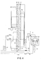
- Fig. 4 is a schematic view of an outdoor heat exchanger according to the embodiment of the present invention.
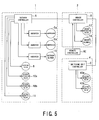
- Fig. 5 is a control system diagram of the multi-type air conditioner according to the embodiment of the present invention.
- A first embodiment of the present invention will be described hereunder with reference to the accompanying drawings.
- Note that in the embodiment described below, the terms "upper", "lower", "right", "left, and the like showing directions are used herein in an illustrated state of the air conditioner or in view of a usual installation state thereof.
- A multi-type air conditioner according to the present invention is composed of an
outdoor unit 1 and a plurality ofindoor units 2. Theoutdoor unit 1 is connected to the plurality ofindoor units 2 by a main pipe 3, which is composed of aliquid pipe 3a, a gas ejection pipe 3b, and agas suction pipe 3c, through switching units 4 for switching operations of theindoor units 2 to heating or cooling. - In the present invention, four sets of the
indoor units switching units - The
outdoor unit 1 accommodates two sets ofcapacity variable compressors oil separator 7, a four-way valve 8, a firstoutdoor heat exchanger 9a, a secondoutdoor heat exchanger 9b, a firstoutdoor expansion valve 10a, a secondoutdoor expansion valve 10b, a refrigerantamount adjustment tank 12, a gas-liquid separator 14, anoutdoor blower 15, and an outdoorelectric parts box 21, and the like. - The outdoor
electric parts box 21 accommodates an outdoor controller A and inverters for controlling theoutdoor blower 15 and thecompressor - The
indoor units 2 accommodateindoor heat exchangers 16,indoor expansion valves 17,indoor blowers 18, and an indoor controller B. - The switching units 4 accommodate liquid
pipe connection pipes 41 for connecting the liquid pipe 3 to the liquid sides of theindoor heat exchangers 16, gasside connection pipes 42 for selectively connecting the gas ejection pipe 3b and thegas suction pipe 3c to the gas sides of theindoor heat exchangers 16,electromagnetic valves - The inverters for driving the
compressor outdoor blower 15, the four-way valve 8, the firstoutdoor expansion valve 10a, the secondoutdoor expansion valve 10b, and anelectromagnetic valve 11 are connected to the outdoor controller A. - The
indoor expansion valves 17 and theindoor blowers 18 are also connected to the indoor controller B. - Further, the
electromagnetic valves - In addition, the outdoor controller A determines opening and/or closing operation and degrees of openings of the various, valves in accordance with the inputs from various sensors (not shown) such as temperature sensors, pressure sensors, and the like disposed to the
outdoor unit 1 and theindoor units 2 and also in accordance with the inputs from remote controllers RC connected to theindoor units 2, thereby controlling the various valves through the indoor controller B and the switching unit controller C. - Next, the
outdoor unit 1 having a structure mentioned below will be explained. - The
outdoor unit 1 has ahorizontal partition plate 22 disposed in an approximately intermediate portion in a vertical direction, and the inside of theoutdoor unit 1 is vertically partitioned by thehorizontal partition plate 22. - An upper compartment on the
horizontal partition plate 22 is arranged as aheat exchange chamber 23, and a lower compartment under it is arranged as amachine chamber 24. - The outer periphery of the
heat exchange chamber 23 and themachine chamber 24 is surrounded by a plurality ofside panels 25 which form an outer peripheral wall, and the upper surface of theheat exchange chamber 23 is closed by atop plate 26 having a cylindrical blow-outport 28. Abottom plate 27 is disposed to the bottom of themachine chamber 24, and thecompressors liquid separator 14, theelectromagnetic valve 11, and a refrigerant pipe for connecting them, the outdoorelectric parts box 21, and the like are disposed on thebottom plate 27. - The first and second
outdoor heat exchangers heat exchange chamber 23 so as to face side surfaces thereof, and the secondoutdoor heat exchangers 9b are disposed to the lower portions of the firstoutdoor heat exchangers 9a on the upstream side thereof in an air flow direction. - The first and second
outdoor expansion valves outdoor blower 15 is disposed to an uppermost central portion of theheat exchange chamber 23. - Outdoor
air suction ports 29 composed of a plurality of holes are formed to theside panels 25 in confrontation with the first and secondoutdoor heat exchangers - When the
outdoor blower 15 is operated, an air flow path is formed such that outdoor air flows through the first and secondoutdoor heat exchangers port 28 after being guided into theheat exchange chamber 23. - Each of the first and second
outdoor heat exchangers heat exchange pipes 31, which pass through thefins 30 in a thickness direction; and a plurality ofU-shaped pipes 32 for forming refrigerant flow paths by sequentially coupling the ends of theheat exchange pipes 31. - The
heat exchange pips 31 are disposed in a plurality of rows in the lengthwise direction of thefins 30 and disposed in a plurality of columns in the air flow direction of thefins 30. Here, theheat exchange pips 31 are disposed to form heat exchange pipe trains L1, L2, L3 of, for example, 30 rows in the lengthwise direction of thefins 30 and three columns in the air flow direction from upstream thereof. - The first and second
outdoor heat exchangers - When the first
outdoor heat exchanger 9a is used as a condenser', the refrigerant flow path thereof is divided into a plurality of flow paths by a gas sideflow dividing pipe 33 disposed on the gas side of the firstoutdoor heat exchanger 9a, and the divided flow paths converge in a liquid sideflow separation pipe 34 disposed to the liquid side. When the firstoutdoor heat exchanger 9a is used as an evaporator, the refrigerant flow path thereof is divided into a plurality of flow paths by the liquid sideflow separation pipe 34 and converge in the gas sideflow dividing pipe 33. - The refrigerant flow path of the second
outdoor heat exchanger 9b is formed by using 12 rows of theheat exchange pips 31 from below the heat exchange pipe train L1 located upstream of the air flow direction of the firstoutdoor heat exchanger 9a, to thereby form a single or a plurality of refrigerant flow paths independently of refrigerant flow path of the first outdoor heat exchanger 8a. - Then, the capacity of the second
outdoor heat exchanger 9b is set to 15% to 30% of the capacity of the firstoutdoor heat exchanger 9a. When the capacity of the secondoutdoor heat exchanger 9b exceeds 30% of the capacity of the firstoutdoor heat exchanger 9a, condensation pressure is lowered when an outside temperature is low, thus decreasing a heating capacity. On the other hand, when the capacity of the secondoutdoor heat exchanger 9b is less than 15% of the capacity of the firstoutdoor heat exchanger 9a, the condensation pressure exceeds design pressure when an outside temperature is high, and thus, there is a fear that the air conditioner may not be operated. - Hereunder, a refrigeration cycle of the multi-type air conditioner will be explained with reference to Fig. 1.
- On the
outdoor unit 1 side,ejection ports compressors ejection pipe 6. The other end of theejection pipe 6 is divided into threeejection pipes oil separator 7. Theejection pipe 6a is connected to the gas side of the firstoutdoor heat exchanger 9a through the four-way valve 8, theejection pipe 6b is connected to the gas side of the secondoutdoor heat exchanger 9b, and theejection pipe 6c is connected to an end of the gas ejection pipe 3b through theelectromagnetic valve 11. - The liquid side of the first
outdoor heat exchanger 9a is connected to an end of theliquid pipe 3a through the firstoutdoor expansion valve 10a and the refrigerantamount adjustment tank 12. - The liquid side of the second
outdoor heat exchanger 9b is connected so as to be converged between the firstoutdoor expansion valve 10a and the refrigerantamount adjustment tank 12 through the secondoutdoor expansion valve 10b. - On the other hand,
suction ports compressors suction pipe 13 through thegas liquid separator 14. The other end of thesuction pipe 13 is divided into twosuction pipes 13a, 13b, the suction pipe 13a is connected to the four-way valve 8, and thesuction pipe 13b is connected to an end of thegas suction pipe 3c. - The four-
way valve 8 shows a state that theejection pipe 6 communicates with the firstoutdoor heat exchanger 9a "OFF" by solid lines and a state that thesuction pipe 13 communicates with the firstoutdoor heat exchanger 9a "ON" by broken lines. - On the indoor unit side, each of the
liquid pipe 3a, the gas ejection pipe 3b, and thegas suction pipe 3c is divided into a plurality of pipes, and they are connected to theindoor units units - As described above, the liquid
pipe connection pipes 41 of the switchingunits liquid pipe 3a to the liquid sides of theindoor heat exchangers 16, and the gasside connection pipes 42 selectively connect the gas ejection pipe 3b and thegas suction pipe 3c to the gas sides of theindoor heat exchangers 16. - The gas
side connection pipes 42 are connected, at one ends, to the gas sides of theindoor heat exchangers 16, and the other ends thereof are divided into gasside connection pipes side connection pipes 42a are connected to one end of the gas ejection pipe 3b through theelectromagnetic valves 43a, and the gasside connection pipes 42b are connected to one end of thegas suction pipe 3c through theelectromagnetic valves 43b. - When the
electromagnetic valves 43a are opened and theelectromagnetic valves 43b are closed, the gas ejection pipe 3b communicates with the gas sides of theindoor heat exchangers 16, whereas when theelectromagnetic valves 43a are closed and theelectromagnetic valves 43b are opened, thegas suction pipe 3c communicates with the gas sides of theindoor heat exchangers 16. - The multi-type air conditioner of the present-invention of the above arrangement carries out operations described below according to the required capacities of the
indoor units - When all the
indoor units outdoor heat exchanger 9a is used as an evaporator, and theindoor heat exchangers 16 are used as condensers. - In the
indoor unit 1, theelectromagnetic valve 11 of theejection pipe 6c is opened and a high pressure gas refrigerant, which is ejected from either one or both of thecompressors ejection pipes - At that time, the four-
way valve 8 is turned on to thereby communicate the gas side of the firstoutdoor heat exchanger 9a with the suction pipe 13a. In order to use the firstoutdoor heat exchanger 9a as the evaporator, the firstoutdoor expansion valve 10a is opened a predetermined degree of angle, and the secondoutdoor expansion valve 10b is entirely closed because the secondoutdoor heat exchanger 9b is not used. - The
electromagnetic valves 43a of the switching units 4 are opened and theelectromagnetic valves 43b thereof are closed. With this operation, the gas ejection pipe 3b communicates with the gas sides of theindoor heat exchangers 16. The high pressure gas refrigerant that flows in the gas ejection pipe 3b enters the gas sides of theindoor heat exchangers 16 through the gasside connection pipes 42a, theelectromagnetic valves 43a, and the gasside connection pipes 42. - In the
indoor units 2, theindoor heat exchangers 16 are used as condensers, and theindoor expansion valves 17 are opened at a predetermined degree of angle, respectively, so as to adjust a flow rate. - The high pressure gas refrigerant, which has entered the
indoor heat exchangers 16, exchanges heat with the indoor air introduced into the indoor units by theindoor blowers 18 and condenses, and then, it flows out from the liquid sides of theindoor heat exchangers 16. The indoor air subjected to the heat exchanging with the refrigerant is made to hot air and supplied to the outside of theindoor units 2 by means of theindoor blowers 18. - The high pressure liquid refrigerant, which has flown out from the liquid sides of the
indoor heat exchangers 16, enters theliquid pipe 3a through theindoor expansion valves 17 and the liquidpipe connection pipes 41. - The high pressure liquid refrigerant, which has entered the
liquid pipe 3a, returns to theoutdoor unit 1, passes through the refrigerantamount adjustment tank 12, and then enters the liquid sideflow separation pipe 34 after its pressure is reduced during the passing through the firstoutdoor expansion valve 10a. The refrigerant, which is caused to separately flow in the plurality of refrigerant flow paths by the liquid sideflow separation pipe 34, enters the firstoutdoor heat exchanger 9a from the liquid side thereof. - The refrigerant, which has entered the first
outdoor heat exchanger 9a, exchanges heat with the outdoor air guided into theheat exchange chamber 23 by theoutdoor blower 15, is made to a low pressure gas refrigerant, and then flows out from the firstoutdoor heat exchanger 9a. The outdoor air subjected to the heat exchanging with the refrigerant is cooled and blown out from the blow-outport 28 by theoutdoor blower 15. - The low pressure gas refrigerant, which has flown out from the first
outdoor heat exchanger 9a, converses in the gas sideflow dividing pipe 33, enters the suction pipe 13a through the four-way valve 8, and is then sucked into either one or both of thecompressors suction pipe 13 and thegas liquid separator 14. - When all the
indoor units 2 perform the cooling operation, the multi-type air conditioner performs the full cooling operation. In this operation, the firstoutdoor heat exchanger 9a is used as a condenser, and theindoor heat exchangers 16 are used as evaporators. - In the
outdoor unit 1, theelectromagnetic valve 11 of theejection pipe 6c is closed, and the four-way valve 8 is turned off. - A high pressure gas refrigerant ejected from either one or both of the
compressors flow separation pipe 33 through theejection pipes way valve 8. The refrigerant, which has been separately flown into a plurality of refrigerant flow paths by the gas sideflow separation pipe 33, enters the firstoutdoor heat exchanger 9a from the gas side thereof and exchanges heat with the outdoor air guided into theheat exchange chamber 23 by theoutdoor blower 15, and condenses to a high pressure liquid refrigerant, which then flows out from the firstoutdoor heat exchanger 9a. The outdoor air subjected to the heat exchanging with the refrigerant is heated and blown out from the blow-outport 28 by means of theoutdoor blower 15. - The high pressure liquid refrigerant, which has been flown out from the first
outdoor heat exchanger 9a, converges in the liquid sideflow separation pipe 34, and then enters the liquid pipe 3b through the firstoutdoor expansion valve 10a and the refrigerantamount adjustment tank 12. - In order to use the first
outdoor heat exchanger 9a as the condenser, the firstoutdoor expansion valve 10a is opened at a predetermined degree of angle, and the secondoutdoor expansion valve 10b is entirely closed because the secondoutdoor heat exchanger 9b is not used. - Since the four-
way valve 8 is turned off and theelectromagnetic valve 11 is closed, the gas ejection pipe 3b is shut off and the refrigerant does not flow. - The
electromagnetic valves 43a of the switching units 4 are closed, and theelectromagnetic valves 43b thereof are opened. With this operation, thegas suction pipe 3c communicates with the gas sides of theindoor heat exchangers 16. The high pressure liquid refrigerant, which flows in theliquid pipe 3a, enters the liquid sides of theindoor heat exchangers 16 through the liquidpipe connection pipe 41. - In the
indoor units 2, theindoor heat exchangers 16 are used as evaporators, and theindoor expansion valves 17 are opened at a predetermined degree of angle, respectively, so as to reduce the pressure of the refrigerant. - The high pressure liquid refrigerant, which has entered the
indoor heat exchangers 16 through theindoor expansion valves 17, exchanges heat with the indoor air guided into the indoor units by theindoor blowers 18 and is evaporated. Then, the refrigerant flows out from the gas sides of theindoor heat exchangers 16. The indoor air subjected to the heat exchanging with the refrigerant is made to cool air and supplied to the outside of theindoor units 2 by means of theindoor blowers 18. - The low pressure gas refrigerant, which has been flown out from the gas sides of the
indoor heat exchangers 16, enters thegas suction pipe 3c through the gasside connection pipes 42, theelectromagnetic valves 43b, and the gasside connection pipes 42b. - The low pressure gas refrigerant, which has entered the
gas suction pipe 3c, returns to theoutdoor unit 1 and sucked into either one or both of thecompressors suction pipe gas liquid separator 14. - When the sum of a heating request capacity requested by the indoor side exceeds the sum of a cooling request capacity requested thereby, the multi-type air conditioner performs the simultaneous cooling/heating operation with mainly heating. When it is assumed that, for example, the
indoor units 2a, 2b, 2c carry out the heating operation and theindoor unit 2d carries out the cooling operation, the firstoutdoor heat exchanger 9a and theindoor heat exchanger 16 of the indoor unit performing the cooling operation are used as evaporators, and theindoor heat exchangers 16 of the indoor units performing the heating operation are used as condensers. - In the
outdoor unit 1, theelectromagnetic valve 11 of theejection pipe 6c is opened, and a high pressure gas refrigerant ejected from either one or both of thecompressors ejection pipe way valve 8 is turned on, and the gas side of the firstoutdoor heat exchanger 9a communicates with the suction pipe 13a. - In order to use the first
outdoor heat exchanger 9a as the evaporator, the firstoutdoor expansion valve 10a is opened at a predetermined degree of angle, and the secondoutdoor expansion valve 10b is entirely closed because the secondoutdoor heat exchanger 9b is not used. - The
electromagnetic valves 43a of the switchingunits electromagnetic valves 43b thereof are closed. In theswitching unit 4d, theelectromagnetic valve 43a is closed, and theelectromagnetic valve 43b thereof is opened. With this operation, the gas ejection pipe 3b communicates with the gas sides of theindoor heat exchangers 16 of theindoor units 2a, 2b, 2c, and thegas suction pipe 3c communicates with theindoor heat exchanger 16 of theindoor unit 2d. - The high pressure gas refrigerant, which flows in the gas ejection pipe 3b, enters the gas sides of the
indoor heat exchangers 16 of theindoor units 2a, 2b, 2c through the gasside connection pipes 42a of the switchingunits electromagnetic valves 43a, and the gasside connection pipes 42a. - In the
indoor units 2a, 2b, 2c, theindoor heat exchanger 16 are used as condensers, and theindoor expansion valves 17 are opened at a predetermined degree of angle, respectively, so as to adjust a flow rate. - After the high pressure gas refrigerant, which has entered the
indoor heat exchangers 16 of theindoor units 2a, 2b, 2c, exchanges heat with the indoor air guided into the indoor units by theindoor blowers 18 and condenses, it flows out from the liquid sides of theindoor heat exchangers 16. - The indoor air subjected to the heat exchanging with the refrigerant is made to hot air and supplied to the outside of the
indoor units 2a, 2b, 2c by means of theindoor blowers 18. The high pressure liquid refrigerant, which has flown out from the liquid sides of theindoor heat exchangers 16 of theindoor units 2a, 2b, 2c enters theliquid pipe 3a through theindoor expansion valves 17 and the liquidpipe connection pipes 41 of the switchingunits liquid pipe 3a, is separated to a refrigerant returned to theoutdoor unit 1 and a refrigerant that enters theindoor unit 2d for carrying out the cooling operation. - The refrigerant, which has returned from the
liquid pipe 3a to theoutdoor unit 1, is subjected to the pressure reduction by theoutdoor expansion valve 10a after passing through the refrigerantamount adjustment tank 12 and enters the liquid sideflow separation pipe 34. The refrigerant, which has been separated to a plurality of refrigerant flow paths by the liquid sideflow separation pipe 34, enters the firstoutdoor heat exchanger 9a from the liquid side thereof. - The refrigerant, which has entered the first
outdoor heat exchanger 9a, exchanges heat with the outdoor air guided into theheat exchange chamber 23 by means of theoutdoor blower 15, is made to a low pressure gas refrigerant, and flows out from the firstoutdoor heat exchanger 9a. The outdoor air subjected to the heat exchanging with the refrigerant is cooled and blown out from the blow-outport 28 by theoutdoor blower 15. The low pressure gas refrigerant, which has flown out from the firstoutdoor heat exchanger 9a, converges in the gas sideflow separation pipe 33 and then enters the suction pipe 13a through the four-way valve 8. - On the other hand, the refrigerant, which has separately entered the
indoor unit 2d, in the cooling operation in theliquid pipe 3a, enters the liquid side of theindoor heat exchanger 16 through the liquidpipe connection pipe 41 of theswitching unit 4d. - In the
indoor unit 2d, theindoor heat exchanger 16 is used as an evaporator, and the indoor expansion valve is opened at a predetermined degree of angle to reduce the pressure of the refrigerant. The high pressure liquid refrigerant, which has entered theindoor heat exchanger 16 of theindoor unit 2d through theindoor expansion valve 17, exchanges the heat with the indoor air guided into the indoor unit by means of theindoor blower 18 and is evaporated and then flows out from the gas side of theindoor heat exchanger 16. - The indoor air subjected to the heat exchanging with the refrigerant is made to cool the air and supplied to the outside of the
indoor unit 2d by means of theindoor blower 18. The low pressure gas refrigerant, which has flown out from the gas side of theindoor heat exchanger 16 of theindoor unit 2d, enters thegas suction pipe 3c through the gasside connection pipe 42, theelectromagnetic valves 43b, and the gasside connection pipe 42b of theswitching unit 4d. The refrigerant, which has entered thegas suction pipe 3c, returns to the outdoor unit, enters thesuction pipe 13b, and then converges with the refrigerant, which has returned from theindoor units 2a, 2b, 2c for heating to theoutdoor unit 1 and flown into the suction pipe 13a, in thesuction pipe 13 and sucked into either one or both of thecompressors gas liquid separator 14. - When the sum of a cooling request capacity requested by the indoor side exceeds the sum of a heating request capacity requested thereby, the multi-type air conditioner performs simultaneous cooling/heating operation with mainly cooling operation. When it is assumed, for example, that the
indoor units 2a, 2b, 2c carry out the cooling operation and theindoor unit 2d carries out the heating operation, the second outdoor heat exchanger 8b and theindoor heat exchanger 16 of the indoor unit performing the heating operation are used as condensers, and theindoor heat exchangers 16 of the indoor units performing the cooling operation are used as evaporators. - In the
indoor unit 1, the four-way valve 8 is turned on, theelectromagnetic valve 11 of theejection pipe 6c and the secondoutdoor expansion valve 10b are opened, a high pressure gas refrigerant ejected from either one or both of thecompressors outdoor heat exchange 9b through theejection pipes ejection pipe electromagnetic valve 11. - In order to use the second
outdoor heat exchanger 9b as the condenser, the secondoutdoor expansion valve 10b is opened at a predetermined degree of angle, and the firstoutdoor expansion valve 10a is closed because the firstoutdoor heat exchanger 9a is not used. The high pressure gas refrigerant, which has entered the secondoutdoor heat exchanger 9b, exchanges heat with the outdoor air guided into theheat exchange chamber 23 by means of theoutdoor blower 15 and condenses, and then flows out from the secondoutdoor heat exchanger 9b in a high pressure liquid state. - The outdoor air subjected to the heat exchanging with the refrigerant is heated and blown out from the blow-out
port 28 by theoutdoor blower 15. The high pressure liquid refrigerant, which has flown out from the secondoutdoor heat exchanger 9b, enters the liquid pipe 3b through the secondoutdoor expansion valve 10b and the refrigerantamount adjustment tank 12. - The
electromagnetic valves 43b of the switchingunits electromagnetic valves 43a thereof are closed. In theswitching unit 4d, theelectromagnetic valve 43b is closed, and theelectromagnetic valve 43a is opened. With this operation, the gas ejection pipe 3b communicates with the gas side of theindoor heat exchanger 16 ofindoor unit 2d, and thegas suction pipe 3c communicates with the gas sides of theindoor heat exchangers 16 of theindoor unit 2a, 2b, 2c. - The high pressure gas refrigerant, which flows in the gas ejection pipe 3b, enters the gas side of the
indoor heat exchanger 16 of theindoor unit 2d through the gasside connection pipe 42a, theelectromagnetic valve 43a, and the gasside connection pipe 42a of theswitching unit 4d. - In the
indoor unit 2d, theindoor heat exchanger 16 is used as the condenser, and theindoor expansion valve 17 is opened at a predetermined degree of angle to adjust a flow rate. The high pressure gas refrigerant, which has entered theindoor heat exchanger 16, exchanges heat with the indoor air guided into theindoor unit 2d by theindoor blower 18 and condenses, and then flows out from the liquid side of theindoor heat exchanger 16. - The indoor air subjected to the heat exchanging with the refrigerant is made to hot air and supplied to the outside of the
indoor unit 2d by means of theindoor blower 18. - The high pressure liquid refrigerant, which has flown from the liquid side of the
indoor heat exchanger 16, enters theliquid pipe 3a through theindoor expansion valve 17 and the liquidpipe connection pipe 41 of theswitching unit 4d. The high pressure liquid refrigerant, which has entered theliquid pipe 3a from theoutdoor unit 2d, converges with the high pressure liquid refrigerant condensed by the secondoutdoor heat exchanger 9b. The converged high pressure liquid refrigerant enters the liquid sides of theindoor heat exchangers 16 through the liquidpipe connection pipes 41 of theswitching unit - In the
indoor units 2a, 2b, 2c, theindoor heat exchangers 16 are used as evaporators, and theindoor expansion valves 17 are opened at a predetermined degree of angle, respectively, so as to reduce the pressure of the refrigerant. The high pressure liquid refrigerant, which has entered theindoor heat exchangers 16 through theindoor expansion valves 17, exchanges heat with the indoor air guided into theindoor units 2a, 2b, 2c by theindoor blowers 18 and evaporates, and then flows out from gas sides of theindoor heat exchangers 16. - The indoor air subjected to the heat exchanging with the refrigerant is made to cool the air and supplied to the outside of the
indoor units 2a, 2b, 2c by means theindoor blowers 18. - The low pressure gas refrigerant, which has flown out from the gas sides of the
indoor heat exchangers 16 of theindoor units 2a, 2b, 2c, enters thegas suction pipe 3c through the gasside connection pipes 42, theelectromagnetic valves 43b, and gasside connection pipes 42b of theswitching unit gas suction pipe 3c, returns to theoutdoor unit 1 and sucked into thecompressors suction pipes gas liquid separator 14. - In the respective operations described above, since the
outdoor blower 15 is installed in the upward blowing-out mode as shown in Fig. 3, the flow rate of the outdoor air guided into theheat exchange chamber 23 is smaller in a lower portion than that in an upper portion in themachine chamber 23. Accordingly, the firstoutdoor heat exchanger 9a tends to have a large heat exchanging amount and the secondoutdoor heat exchanger 9b tends to have a small heat exchanging amount. - Since the second
outdoor heat exchangers 9b are disposed to the lower portions of first columns of the firstoutdoor heat exchangers 9a, in the simultaneous cooling/heating operation with mainly cooling operation in which the secondoutdoor heat exchanger 9b is used as the condenser, a sufficient condensing temperature can be kept in the indoor unit for carrying out the heating operation without accelerating the heat exchanging even if an outside temperature is low, thereby preventing the degradation of the heating capacity. - Further, since the capacity of the second
outdoor heat exchanger 9b is set to 15% to 30% of the firstoutdoor heat exchanger 9a, when an outside temperature is low, the condensation pressure can be kept, and when an outside temperature is high, the condensation pressure does not exceed the design pressure, thereby performing the comfortable air conditioning at all times. - Furthermore, in the overall (full) heating operation, in which the first
outdoor heat exchangers 9a are used as the evaporators, and in the simultaneous cooling/heating operation with mainly heating operation, when the operation is continued for a long time, the lower portions of the firstoutdoor heat exchangers 9a are frosted and the heat exchanging efficiency is deteriorated. To cope with this problem, defrosting operation is carried out. However, the frost melted by the defrosting operation is liable to drop along thefins 30 and to accumulate in the lower portions of theoutdoor heat exchangers 9a. Thus, when the overall heating operation, in which the firstoutdoor heat exchangers 9a are used as the evaporators, and the simultaneous cooling/heating operation with mainly heating operation is carried out again, the accumulating frost and water are refrigerated, and thus, the outdoor heat exchangers may be broken. - When the second
outdoor heat exchangers 9b are not used as the condensers without being supplied with the high pressure gas refrigerant from theejection pipe 6b different from the abovementioned, the secondoutdoor expansion valve 10b is closed, and thus, the high pressure gas refrigerant is forcibly accumulated. Therefore, in the portion in which the high pressure gas refrigerant is forcibly accumulated, the frosting in the portion can be suppressed as well as the disadvantage mentioned above due to the suppression of the defrosting. Since the frosting can be suppressed, the heat exchanging amount of the firstoutdoor heat exchangers 9a is not reduced, thereby effectively performing the operation. - Still furthermore, since the first and second
outdoor heat exchangers common fins 30, the number of parts can be reduced, thereby reducing the cost as well as the space of a housing. - In addition, it is also possible to commonly arrange a standard multi-type air conditioner for carrying out the overall cooling operation or the overall heating operation and the
heat exchange chamber 23 of theoutdoor unit 1. With this arrangement, the cost can be further reduced. - It should be noted that the present invention is mot limited to the above embodiment and can be variously modified within a scope without departing from the scopes of the present invention.
Claims (3)
- A multi-type air conditioner comprising:an outdoor unit provided with an outdoor controller;a plurality of indoor units provided with indoor controllers;switching units for switching operation of the plurality of indoor units; anda main pipe composed of a liquid pipe, a gas ejection pipe and a gas suction pipe for connecting the outdoor unit to the plurality of indoor units through the switching units, in which an overall cooling operation in which all the indoor units performs a cooling operation, an overall heating operation in which all the indoor units performs a heating operation and a simultaneous cooling/heating operation in which the indoor units perform cooling and heating operation simultaneously,wherein the outdoor unit constitutes an outdoor heat exchanging unit including a first outdoor heat exchanger used as a condenser in the cooling operation and used as an evaporator in the heating operation and a second outdoor heat exchanger used as a condenser in the simultaneous cooling/heating operation, and the second outdoor heat exchanger is disposed on an upstream side of the first outdoor heat exchanger in an air flow direction.
- The air conditioner according to claim 1, wherein the outdoor unit includes an outdoor blower blowing out air upward, the outdoor blower is disposed above the first outdoor heat exchanger, and the second outdoor heat exchanger is disposed below the first outdoor heat exchanger.
- The air conditioner according to claim 1, wherein the second outdoor heat exchanger has a capacity of 15% to 30% with respect to a capacity of the first outdoor heat exchanger.
Applications Claiming Priority (2)
| Application Number | Priority Date | Filing Date | Title |
|---|---|---|---|
| JP2004194976 | 2004-06-30 | ||
| PCT/JP2005/011725 WO2006003860A1 (en) | 2004-06-30 | 2005-06-27 | Multi-type air conditioner |
Publications (3)
| Publication Number | Publication Date |
|---|---|
| EP1793179A1 true EP1793179A1 (en) | 2007-06-06 |
| EP1793179A4 EP1793179A4 (en) | 2008-10-22 |
| EP1793179B1 EP1793179B1 (en) | 2018-04-11 |
Family
ID=35782669
Family Applications (1)
| Application Number | Title | Priority Date | Filing Date |
|---|---|---|---|
| EP05765138.2A Expired - Lifetime EP1793179B1 (en) | 2004-06-30 | 2005-06-27 | Multi-type air conditioner |
Country Status (5)
| Country | Link |
|---|---|
| EP (1) | EP1793179B1 (en) |
| JP (1) | JP4499733B2 (en) |
| KR (1) | KR100833560B1 (en) |
| CN (1) | CN100552313C (en) |
| WO (1) | WO2006003860A1 (en) |
Cited By (8)
| Publication number | Priority date | Publication date | Assignee | Title |
|---|---|---|---|---|
| EP2047183A4 (en) * | 2006-07-29 | 2011-03-09 | Lg Electronics Inc | Simulataneous heating/cooling multi air conditioner |
| EP2236383A3 (en) * | 2009-03-31 | 2011-08-17 | Hitachi, Ltd. | Heat pump air conditioning system for railway vehicle |
| EP2693139A1 (en) * | 2012-08-03 | 2014-02-05 | Hitachi Appliances, Inc. | Refrigeration cycle apparatus and refrigeration unit and air-conditioning system equipped with the refrigeration cycle apparatus |
| WO2016107164A1 (en) * | 2014-12-29 | 2016-07-07 | 山东创尔沃热泵技术股份有限公司 | Main engine outer casing structure of air cooled heat pump unit |
| EP3150941A4 (en) * | 2014-05-28 | 2017-05-31 | Daikin Industries, Ltd. | Refrigeration device |
| US9784481B2 (en) | 2013-10-07 | 2017-10-10 | Daikin Industries, Ltd. | Heat-recovery-type refrigerating apparatus |
| EP4328526A1 (en) * | 2022-08-25 | 2024-02-28 | Carrier Corporation | Heat pump system and control method thereof |
| EP4368917A4 (en) * | 2021-10-07 | 2024-10-30 | Daikin Industries, Ltd. | Heat source unit and air-conditioning device |
Families Citing this family (10)
| Publication number | Priority date | Publication date | Assignee | Title |
|---|---|---|---|---|
| JP4922669B2 (en) * | 2006-06-09 | 2012-04-25 | 日立アプライアンス株式会社 | Air conditioner and heat exchanger for air conditioner |
| CN102721122A (en) * | 2012-05-11 | 2012-10-10 | 常州新德冷机有限公司 | Outdoor unit body of air conditioner |
| JP6003635B2 (en) * | 2012-12-28 | 2016-10-05 | ダイキン工業株式会社 | AIR CONDITIONER AND AIR CONDITIONER CONSTRUCTION METHOD |
| JP6149485B2 (en) * | 2013-04-19 | 2017-06-21 | ダイキン工業株式会社 | Refrigeration equipment |
| CN103353147B (en) * | 2013-06-28 | 2016-05-25 | 青岛海信日立空调系统有限公司 | The full heat treatment multi-online air-conditioning system of three control and humiture method for independently controlling |
| CN104633841A (en) * | 2013-11-15 | 2015-05-20 | 广东美的暖通设备有限公司 | Air conditioner and control method thereof |
| JP6179414B2 (en) * | 2014-01-30 | 2017-08-16 | ダイキン工業株式会社 | Heat exchanger for heat source unit of refrigeration apparatus, and heat source unit including the same |
| GB2557523B (en) * | 2015-10-27 | 2020-09-30 | Mitsubishi Electric Corp | Air-conditioning apparatus and outdoor unit for air-conditioning apparatus |
| KR102409975B1 (en) * | 2020-09-07 | 2022-06-15 | 엘지전자 주식회사 | Air Conditioner |
| CN116075673A (en) * | 2020-09-15 | 2023-05-05 | 东芝开利株式会社 | air conditioner |
Family Cites Families (10)
| Publication number | Priority date | Publication date | Assignee | Title |
|---|---|---|---|---|
| US4332137A (en) * | 1979-10-22 | 1982-06-01 | Carrier Corporation | Heat exchange apparatus and method having two refrigeration circuits |
| JPS62255762A (en) | 1986-04-30 | 1987-11-07 | 株式会社日立製作所 | Air conditioner |
| JP2698175B2 (en) | 1989-07-07 | 1998-01-19 | 三洋電機株式会社 | Air conditioner |
| JP2765970B2 (en) | 1989-07-31 | 1998-06-18 | 三洋電機株式会社 | Air conditioner |
| JPH05332637A (en) * | 1992-05-29 | 1993-12-14 | Sanyo Electric Co Ltd | Air conditioner |
| KR100225636B1 (en) * | 1997-05-20 | 1999-10-15 | 윤종용 | Air Conditioning for Air Conditioning |
| JPH11118199A (en) | 1997-10-20 | 1999-04-30 | Hitachi Ltd | Air conditioner |
| KR20030012628A (en) * | 2001-08-02 | 2003-02-12 | 주식회사 엘지이아이 | Air-conditioner |
| JP3669337B2 (en) * | 2002-02-25 | 2005-07-06 | ダイキン工業株式会社 | Air conditioner outdoor air conditioning unit |
| KR20060038268A (en) * | 2004-10-29 | 2006-05-03 | 엘지전자 주식회사 | Air conditioning control system of multi air conditioner |
-
2005
- 2005-06-27 CN CNB2005800258188A patent/CN100552313C/en not_active Expired - Lifetime
- 2005-06-27 WO PCT/JP2005/011725 patent/WO2006003860A1/en not_active Ceased
- 2005-06-27 EP EP05765138.2A patent/EP1793179B1/en not_active Expired - Lifetime
- 2005-06-27 JP JP2006528661A patent/JP4499733B2/en not_active Expired - Fee Related
- 2005-06-27 KR KR1020077002357A patent/KR100833560B1/en not_active Expired - Fee Related
Cited By (11)
| Publication number | Priority date | Publication date | Assignee | Title |
|---|---|---|---|---|
| EP2047183A4 (en) * | 2006-07-29 | 2011-03-09 | Lg Electronics Inc | Simulataneous heating/cooling multi air conditioner |
| US8091377B2 (en) | 2006-07-29 | 2012-01-10 | Lg Electronics Inc. | Simultaneous heating/cooling multi air conditioner |
| EP2236383A3 (en) * | 2009-03-31 | 2011-08-17 | Hitachi, Ltd. | Heat pump air conditioning system for railway vehicle |
| EP2693139A1 (en) * | 2012-08-03 | 2014-02-05 | Hitachi Appliances, Inc. | Refrigeration cycle apparatus and refrigeration unit and air-conditioning system equipped with the refrigeration cycle apparatus |
| US9784481B2 (en) | 2013-10-07 | 2017-10-10 | Daikin Industries, Ltd. | Heat-recovery-type refrigerating apparatus |
| EP3150941A4 (en) * | 2014-05-28 | 2017-05-31 | Daikin Industries, Ltd. | Refrigeration device |
| US10480837B2 (en) | 2014-05-28 | 2019-11-19 | Daikin Industries, Ltd. | Refrigeration apparatus |
| WO2016107164A1 (en) * | 2014-12-29 | 2016-07-07 | 山东创尔沃热泵技术股份有限公司 | Main engine outer casing structure of air cooled heat pump unit |
| EP4368917A4 (en) * | 2021-10-07 | 2024-10-30 | Daikin Industries, Ltd. | Heat source unit and air-conditioning device |
| EP4328526A1 (en) * | 2022-08-25 | 2024-02-28 | Carrier Corporation | Heat pump system and control method thereof |
| US12595941B2 (en) | 2022-08-25 | 2026-04-07 | Carrier Corporation | Heat pump system and control method thereof |
Also Published As
| Publication number | Publication date |
|---|---|
| JP4499733B2 (en) | 2010-07-07 |
| KR100833560B1 (en) | 2008-05-29 |
| CN100552313C (en) | 2009-10-21 |
| JPWO2006003860A1 (en) | 2008-04-17 |
| CN1993587A (en) | 2007-07-04 |
| EP1793179B1 (en) | 2018-04-11 |
| EP1793179A4 (en) | 2008-10-22 |
| KR20070061788A (en) | 2007-06-14 |
| WO2006003860A1 (en) | 2006-01-12 |
Similar Documents
| Publication | Publication Date | Title |
|---|---|---|
| EP1793179B1 (en) | Multi-type air conditioner | |
| EP2759785B1 (en) | Refrigeration device | |
| KR100437802B1 (en) | Multi-type air conditioner for cooling/heating the same time | |
| EP1420216B1 (en) | Air conditioner and operation method thereof | |
| US10655917B2 (en) | Heat exchanger and air conditioning device | |
| CN111664549A (en) | Air conditioner | |
| KR100208144B1 (en) | Airflow Switching Air Conditioning | |
| JP4909093B2 (en) | Multi-type air conditioner | |
| GB2569898A (en) | Air conditioner | |
| JPWO2018047331A1 (en) | Air conditioner | |
| WO2013001976A1 (en) | Air conditioner | |
| US6826924B2 (en) | Heat pump apparatus | |
| KR20060039739A (en) | Outdoor unit with adjustable heat exchange capacity and air conditioner | |
| WO2021014520A1 (en) | Air-conditioning device | |
| US20200200477A1 (en) | Heat exchanger and heat exchange unit including the same | |
| JP3985831B2 (en) | Heat exchanger for outdoor unit | |
| JP2006343052A (en) | Cooling and heating simultaneous multi air conditioner | |
| JP2008157557A (en) | Air conditioner | |
| US20200200476A1 (en) | Heat exchanger | |
| KR20000012499A (en) | An air conditioning system | |
| KR100757969B1 (en) | Parallel air conditioning and air conditioner with high speed defroster | |
| EP1666814B1 (en) | Air conditioning system | |
| KR20220019932A (en) | Outdoor unit of air conditioner | |
| CN222937902U (en) | Air duct machine | |
| CN113776162A (en) | Air conditioner |
Legal Events
| Date | Code | Title | Description |
|---|---|---|---|
| PUAI | Public reference made under article 153(3) epc to a published international application that has entered the european phase |
Free format text: ORIGINAL CODE: 0009012 |
|
| 17P | Request for examination filed |
Effective date: 20061229 |
|
| AK | Designated contracting states |
Kind code of ref document: A1 Designated state(s): FR GB IT |
|
| RBV | Designated contracting states (corrected) |
Designated state(s): FR GB IT |
|
| DAX | Request for extension of the european patent (deleted) | ||
| A4 | Supplementary search report drawn up and despatched |
Effective date: 20080919 |
|
| 17Q | First examination report despatched |
Effective date: 20101025 |
|
| GRAP | Despatch of communication of intention to grant a patent |
Free format text: ORIGINAL CODE: EPIDOSNIGR1 |
|
| RIC1 | Information provided on ipc code assigned before grant |
Ipc: F24F 1/50 20110101ALI20171117BHEP Ipc: F25B 6/04 20060101ALI20171117BHEP Ipc: F25B 13/00 20060101AFI20171117BHEP |
|
| INTG | Intention to grant announced |
Effective date: 20171218 |
|
| GRAS | Grant fee paid |
Free format text: ORIGINAL CODE: EPIDOSNIGR3 |
|
| GRAA | (expected) grant |
Free format text: ORIGINAL CODE: 0009210 |
|
| RAP1 | Party data changed (applicant data changed or rights of an application transferred) |
Owner name: TOSHIBA CARRIER CORPORATION |
|
| AK | Designated contracting states |
Kind code of ref document: B1 Designated state(s): FR GB IT |
|
| REG | Reference to a national code |
Ref country code: GB Ref legal event code: FG4D |
|
| REG | Reference to a national code |
Ref country code: FR Ref legal event code: PLFP Year of fee payment: 14 |
|
| RIC2 | Information provided on ipc code assigned after grant |
Ipc: F25B 13/00 20060101AFI20171117BHEP Ipc: F25B 6/04 20060101ALI20171117BHEP Ipc: F24F 1/50 20110101ALI20171117BHEP |
|
| RIC2 | Information provided on ipc code assigned after grant |
Ipc: F25B 13/00 20060101AFI20171117BHEP Ipc: F25B 6/04 20060101ALI20171117BHEP Ipc: F24F 1/50 20110101ALI20171117BHEP |
|
| PLBE | No opposition filed within time limit |
Free format text: ORIGINAL CODE: 0009261 |
|
| STAA | Information on the status of an ep patent application or granted ep patent |
Free format text: STATUS: NO OPPOSITION FILED WITHIN TIME LIMIT |
|
| 26N | No opposition filed |
Effective date: 20190114 |
|
| PGFP | Annual fee paid to national office [announced via postgrant information from national office to epo] |
Ref country code: GB Payment date: 20240509 Year of fee payment: 20 |
|
| PGFP | Annual fee paid to national office [announced via postgrant information from national office to epo] |
Ref country code: IT Payment date: 20240513 Year of fee payment: 20 Ref country code: FR Payment date: 20240509 Year of fee payment: 20 |
|
| PG25 | Lapsed in a contracting state [announced via postgrant information from national office to epo] |
Ref country code: GB Free format text: LAPSE BECAUSE OF EXPIRATION OF PROTECTION Effective date: 20250626 |
|
| REG | Reference to a national code |
Ref country code: GB Ref legal event code: PE20 Expiry date: 20250626 |