EP1793149B1 - Electromagnetic actuator - Google Patents
Electromagnetic actuator Download PDFInfo
- Publication number
- EP1793149B1 EP1793149B1 EP20060124873 EP06124873A EP1793149B1 EP 1793149 B1 EP1793149 B1 EP 1793149B1 EP 20060124873 EP20060124873 EP 20060124873 EP 06124873 A EP06124873 A EP 06124873A EP 1793149 B1 EP1793149 B1 EP 1793149B1
- Authority
- EP
- European Patent Office
- Prior art keywords
- valve
- armature
- magnet armature
- face
- sealing
- Prior art date
- Legal status (The legal status is an assumption and is not a legal conclusion. Google has not performed a legal analysis and makes no representation as to the accuracy of the status listed.)
- Active
Links
- 238000007789 sealing Methods 0.000 claims description 87
- 230000033001 locomotion Effects 0.000 claims description 35
- 238000013016 damping Methods 0.000 claims description 29
- 230000005540 biological transmission Effects 0.000 claims description 18
- 239000002184 metal Substances 0.000 claims description 3
- 239000004033 plastic Substances 0.000 claims description 2
- 238000000465 moulding Methods 0.000 claims 1
- 239000012530 fluid Substances 0.000 description 7
- 230000002238 attenuated effect Effects 0.000 description 3
- 238000006073 displacement reaction Methods 0.000 description 3
- 238000000034 method Methods 0.000 description 3
- 239000000203 mixture Substances 0.000 description 3
- 230000015572 biosynthetic process Effects 0.000 description 2
- 230000000694 effects Effects 0.000 description 2
- 230000010355 oscillation Effects 0.000 description 2
- 239000000126 substance Substances 0.000 description 2
- 238000002485 combustion reaction Methods 0.000 description 1
- 230000006735 deficit Effects 0.000 description 1
- 238000010586 diagram Methods 0.000 description 1
- 230000001747 exhibiting effect Effects 0.000 description 1
- 230000009969 flowable effect Effects 0.000 description 1
- 239000007789 gas Substances 0.000 description 1
- 230000005484 gravity Effects 0.000 description 1
- 238000009434 installation Methods 0.000 description 1
- 239000007788 liquid Substances 0.000 description 1
- 239000002991 molded plastic Substances 0.000 description 1
- 230000003071 parasitic effect Effects 0.000 description 1
- 230000000750 progressive effect Effects 0.000 description 1
Images
Classifications
-
- F—MECHANICAL ENGINEERING; LIGHTING; HEATING; WEAPONS; BLASTING
- F16—ENGINEERING ELEMENTS AND UNITS; GENERAL MEASURES FOR PRODUCING AND MAINTAINING EFFECTIVE FUNCTIONING OF MACHINES OR INSTALLATIONS; THERMAL INSULATION IN GENERAL
- F16K—VALVES; TAPS; COCKS; ACTUATING-FLOATS; DEVICES FOR VENTING OR AERATING
- F16K31/00—Actuating devices; Operating means; Releasing devices
- F16K31/02—Actuating devices; Operating means; Releasing devices electric; magnetic
- F16K31/06—Actuating devices; Operating means; Releasing devices electric; magnetic using a magnet, e.g. diaphragm valves, cutting off by means of a liquid
- F16K31/0686—Braking, pressure equilibration, shock absorbing
- F16K31/0689—Braking of the valve element
-
- H—ELECTRICITY
- H01—ELECTRIC ELEMENTS
- H01F—MAGNETS; INDUCTANCES; TRANSFORMERS; SELECTION OF MATERIALS FOR THEIR MAGNETIC PROPERTIES
- H01F7/00—Magnets
- H01F7/06—Electromagnets; Actuators including electromagnets
- H01F7/08—Electromagnets; Actuators including electromagnets with armatures
- H01F7/088—Electromagnets; Actuators including electromagnets with armatures provided with means for absorbing shocks
-
- H—ELECTRICITY
- H01—ELECTRIC ELEMENTS
- H01F—MAGNETS; INDUCTANCES; TRANSFORMERS; SELECTION OF MATERIALS FOR THEIR MAGNETIC PROPERTIES
- H01F7/00—Magnets
- H01F7/06—Electromagnets; Actuators including electromagnets
- H01F7/08—Electromagnets; Actuators including electromagnets with armatures
- H01F7/16—Rectilinearly-movable armatures
- H01F7/1607—Armatures entering the winding
Definitions
- the invention relates to an electromagnetic actuator with a cylindrical magnet armature, which is slidably mounted in a hollow cylindrical and closed by a bottom armature space of a coil housing of the actuator between two spaced by a stroke H end positions and in the vicinity of the bottom end position one for damping its movement Serving pressure space between the bottom on the one hand and a floor facing the first end of the magnet armature and a throttle serving as an annular gap on the other hand, wherein for forming the annular gap an inner sealing surface disposed in the magnet armature axial bore, starting from the first end side toward a second end face of the Magnet armature extends, and an inner sealing surface coaxial to the outer sealing surface are provided on a sealing body attached to the coil housing and the pressure chamber with variable height of the annular gap within a in the region of the Bottom near end position extending portion .DELTA.H of the stroke H of the armature with ⁇ H ⁇ H is formed.
- the invention also relates to an electromagnetic hydraulic valve with such an actuator.
- the Indian JP 2002272080 A proposed actuator is part of an electromagnetic control valve with a solenoid operated by the valve lifter whose movement is damped in the region of the upper, the bottom of the bobbin case near end position.
- a pressure builds up in a pressure space between the bottom and the end face of the magnet armature facing the bottom, which-apart from leaks through the guide gap of the magnet armature-can only relieve pressure via an annular gap serving as a throttle.
- This annular gap is between a continuous one Axial bore of the armature and a running in the axial bore shaft formed with the armature firmly bolted valve stem.
- An electromagnetic hydraulic valve with a damped in the end position actuator of the type mentioned is considered from the considered generic JP 58 081281 A out.
- the JP 59 188105 A shows a pneumatically damped piston in the end position.
- the invention is therefore based on the object to avoid these disadvantages and thus to provide an electromagnetic actuator, the armature is motion-damped without significant impairment of the switching dynamics of the actuator with simultaneous targeted influenceability of the switching process.
- this object is achieved in that the armature space is limited by a sleeve housing the lining forming the bottom and made of non-magnetic metal sleeve, on which the sealing body is integrally formed from the ground by deep drawing.
- the sleeve which shields the armature of unwanted electromagnetic forces are used simultaneously as a sealing body, so that the cost and installation costs for an additional, serving as a sealing member in the actuator deleted.
- the height of the annular gap which is variable via its stroke, are available as throttle parameters.
- both the course of the annular gap height and its position with respect to the respective end position largely independent degrees of freedom to optimize the course of movement of the armature.
- the Pressure chamber then depending on the direction of movement of the armature either only as over the annular gap relieving pressure chamber or only as over the annular gap nachsaugender vacuum chamber is effective.
- the position and the height of the annular gap forming the outer sealing surface on the sealing body and the inner sealing surface within the axial bore can also be chosen so that the movement damping of the armature is not effective until final reaching one of the end positions, but is canceled shortly before reaching the end position , This can be advantageous, for example, if in the end position, a rapid pressure equalization in the pressure chamber is desired.
- an electromagnetic hydraulic valve comprising the actuator and the control valve is provided with a valve housing connected to the coil housing.
- the magnet armature is in operative connection with a valve stem extending in the valve stem or is part of this valve stem, which controls the connection between terminals formed in the valve housing for hydraulic fluid.
- Such a distance or component length ratio takes into account component scatters due to unavoidable component length tolerances and ensures that the first closing body always rests completely with its sealing surface on the first sealing seat before the magnet armature reaches the end position lying near the bottom.
- the inner sealing surface of the axial bore and the outer sealing surface of the sealing body can then be positioned relative to one another in such a way that the movement damping is at least partially effective in the region of an idle stroke of the magnet armature. This idle stroke results from the difference L L - (L V + L A ).
- control valve is designed as a 3/2-way switching valve, which has an end-side pressure connection and in each case a radially extending through a lateral surface of the hollow cylindrical valve housing working port and tank connection.
- first sealing seat between the pressure connection and the working connection and a second sealing body corresponding with a second sealing seat between the working connection and the tank connection are arranged.
- the magnet armature should be tubular with a continuous axial bore and the valve tappet designed as a plastic made and axial guide ribs exhibiting molded body.
- the axial guide ribs center the valve stem radially in the valve housing and are with Axialab accountsn, which form the force transmission surface of the valve stem and pass into a floating in the axial bore of the magnet armature centering, on serving as a force transmission surface of the magnet armature second end face of the armature.
- an electromagnetic hydraulic valve comprising the actuator and the control valve is provided with a preferred combination of features explained above.
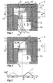
- FIG. 1 shows an electromagnetic actuator 1 with a cylindrical armature 2, which is slidably mounted in a hollow cylindrical and by a bottom 3 closed armature space 4 of a coil housing 5 of the actuator 1 between two spaced by a stroke H end positions.
- the bottom or bottom end position as shown to the left of the centerline of the actuator 1 is designated 6, while that of the bottom 3 is near or top end position as shown to the right of the center line is denoted by 7 below.
- the term fluid is to be understood as meaning all flowable substances and substance mixtures, ie liquids and gases and mixtures thereof.
- a pressure chamber 9 designed as a pressure chamber 8 is enclosed in the region of this end position 7.
- the pressure chamber 9 is bounded on the one hand by the bottom 3 and on the other hand by a first end face 10 of the magnet armature 2 facing the bottom 3 and an annular gap 11.
- the annular gap 11 is formed by an inner sealing surface 12 within an axial bore 13 extending in the magnet armature 2 and an outer sealing surface 14 coaxial with the inner sealing surface 12 on a sealing body 15 extending from the bottom 3 and secured to the coil housing 5.
- the movement damping of the armature 2 is based on the pressurization of the fluid located in the pressure chamber 9, which is displaced over the annular gap 11 by overcoming a throttle resistance in the direction of a bottom 3 remote from the second end face 16 of the armature 2.
- the inner sealing surface 12 is spaced from the outer sealing surface 14 by a damping-free lifting portion H 0 , in conjunction with a variable height H D of the annular gap 11 a tuned to the Hubkoordinate y of the armature 2 damping characteristic can be made.
- Essential parameters for this purpose in addition to the damping-free lifting section H 0, a height a of the inner sealing surface 12 and a height d of the outer sealing surface 14.
- the length of the section .DELTA.H corresponds in this case the sum of the height a of the inner sealing surface 12 and the height d of the outer sealing surface 14 and is selected that the sealing surfaces 12 and 14 no longer overlap immediately before reaching the upper end position 7 of the magnet armature 2. Consequently, the movement of the armature 2 is shortly before the upper end position 7 again without attenuation, since the pressure chamber 9 can relieve rapidly due to the then no longer present annular gap 11.
- the pressure chamber 9 of the actuator 1 according to FIG. 2 during the movement of the armature 2 in the direction of the lower end position 6 as a vacuum chamber 17 is effective. Also in this case, the movement of the armature 2 after the damping-free lifting section H 0 by formation of the annular gap 11 with the height H D , as it results for the intermediate position of the armature 2 shown dotted, attenuated. However, in this case, the movement damping is based on the negative pressure generated in the pressure chamber 9, so that fluid now comes to pressure equalization from the direction of the second end face 16 of the armature 2, overcoming the throttle resistance through the annular gap 11 in the pressure chamber 9.
- the damping characteristic can be coordinated via the design of the inner sealing surface 12 and the outer sealing surface 14.
- the for FIG. 1 and FIG. 2 described damping characteristics combine to the effect that the movement of the armature 2 is attenuated both in the upper end position 7 and in the lower end position 6. This can be achieved, for example, by the fact that the in FIG. 2 shown sealing body 15 to the outer sealing surface 14 according to FIG. 1 is extended. Consequently, the in FIG. 3 illustrated course for the height H D of the annular gap 11 to the in FIG. 3 dashed section shown .DELTA.H 'in the region of the lower end position 6 with respect FIG. 1 or the upper end position 7 with respect FIG. 2 be extended.
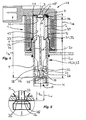
- An in FIG. 4 disclosed electromagnetic hydraulic valve 18 includes the actuator 1 and a control valve 20 designed as a seat valve 19, wherein the movement of the armature 2 based on the in FIG. 1 illustrated principle is attenuated in the upper end position 7.
- Shown is a connected to the coil housing 5 hollow cylindrical valve housing 21 in which an actuated by the armature 2 valve stem 22 controls the connection between formed in the valve housing 21 ports for hydraulic fluid.
- at these connections of the 3/2-way switching valve 23 and adapted to control hydraulically displaceable control elements of a variable valve train of an internal combustion engine suitable control valve 20 is a frontally arranged in the valve housing 21 pressure port P and each radially through a lateral surface 24 of the valve housing 21 extending working port A and tank connection T.
- first closing body 25 which is conical and corresponds with a arranged in the valve housing 21 first sealing seat 26. This serves as an axial stop for the first closing body 25, so that its stroke and, as it were, the stroke of the valve lifter 22 firmly connected to the first closing body 25 is limited in the direction of the upper end position 7 of the magnet armature 2 by the first sealing seat 26.
- the connection between the pressure ports A and T is controlled by a second closing body 27, which corresponds to a second sealing seat 28.
- the armature space 4 is bounded by a sleeve housing 5 lining and the bottom 3 forming sleeve 29 made of non-magnetic metal, which shields the slidingly mounted in the sleeve 29 armature 2 against electromagnetic interference forces.
- the outgoing of the bottom 3 sealing body 15 is integrally formed with the outer sealing surface 14 in a deep-drawing process to the sleeve 29.
- This distance or component length ratio takes into account unavoidable component length tolerances and ensures that the sealing surface 35 of the first closing body 25 always bears completely against the first sealing seat 26 before the magnet armature 2 reaches the upper end position 7 after an idle stroke.
- the idle stroke results from the difference L L - (L V + L A ) and is identical to the distance between the force transmission surface 33 of the valve stem 22 and the force transmission surface 34 of the magnet armature 2, when the sealing surface 35 of the first closing body 25 at the first sealing seat 26th and the armature 2 abut the bottom 3.
- the movement of the armature 2 and the valve stem 22 takes place from the lower end position 6 in the direction of the upper end position 7 only by the force applied to the end-side pressure port P and acting on the valve stem 22 pressing force.
- an undamped magnet armature then there would be the risk that the armature in the upper end position 7 bounces on the bottom 3 and again hits the valve tappet 22, whereby the first closing body 25 would be excited to oscillate with respect to the first sealing seat 26.
- Such oscillations can extend over a relatively long period of time and lead to the initially described disruptive effects with regard to the pressure curve in the hydraulic system to be controlled by the hydraulic valve.
- the pressure chamber 9 limiting annular gap 11 is formed by the inner sealing surface 12 of the axial bore 13 and the outer sealing surface 14 of the sealing body 15 only when the sealing surface 35 of the first closing body 25 of the valve stem 22 is already applied to the first sealing seat 26.
- the portion .DELTA.H in which the movement damping of the armature 2 is effected by partial displacement of the oil-air mixture in the pressure chamber 9 via the annular gap 11, completely within the aforementioned idle stroke L L - (L V + L A ); that is, ⁇ H ⁇ L L - (L V + L A ).
- the height H D of the annular gap 11 increases continuously during the partial section ⁇ H, so that the armature 2 is decelerated until the final end position 7 with progressive damping is finally reached.
- the armature 2 can slide back under the action of gravity to the valve tappet 22 and seat comparatively gently on the axial shoulders 31 of the axial guide ribs 30. Since the inner sealing surface 12 of the axial bore 13 and the outer sealing surface 14 of the sealing body 15 do not overlap in this position, consequently the movement damping of the magnet armature 2 is effective only outside the stroke range of the valve tappet 22. In this respect, the dynamics of the hydraulic valve 18, ie the switching time of the valve stem 22 neither during closing nor during the opening process in which the connection between the pressure port P and the working port A is closed or opened, affected and with the dynamics of a hydraulic valve with undamped magnet armature comparable.
Description
Die Erfindung betrifft einen elektromagnetischen Aktuator mit einem zylindrischen Magnetanker, der in einem hohlzylindrischen und durch einen Boden einseitig verschlossenen Ankerraum eines Spulengehäuses des Aktuators zwischen zwei um einen Hub H beabstandeten Endlagen gleitend gelagert ist und im Bereich der dem Boden nahen Endlage einen zur Dämpfung seiner Bewegung dienenden Druckraum zwischen dem Boden einerseits und einer dem Boden zugewandten ersten Stirnseite des Magnetankers sowie einem als Drossel dienenden Ringspalt andererseits einschließt, wobei zur Bildung des Ringspalts eine Innendichtfläche innerhalb einer im Magnetanker angeordneten Axialbohrung, die ausgehend von der ersten Stirnseite in Richtung einer zweiten Stirnseite des Magnetankers verläuft, und eine zur Innendichtfläche koaxiale Außendichtfläche an einem am Spulengehäuse befestigten Dichtkörper vorgesehen sind und der Druckraum bei veränderlicher Höhe des Ringspalts innerhalb eines im Bereich der dem Boden nahen Endlage verlaufenden Teilabschnitts ΔH des Hubes H des Magnetankers mit ΔH < H gebildet ist.The invention relates to an electromagnetic actuator with a cylindrical magnet armature, which is slidably mounted in a hollow cylindrical and closed by a bottom armature space of a coil housing of the actuator between two spaced by a stroke H end positions and in the vicinity of the bottom end position one for damping its movement Serving pressure space between the bottom on the one hand and a floor facing the first end of the magnet armature and a throttle serving as an annular gap on the other hand, wherein for forming the annular gap an inner sealing surface disposed in the magnet armature axial bore, starting from the first end side toward a second end face of the Magnet armature extends, and an inner sealing surface coaxial to the outer sealing surface are provided on a sealing body attached to the coil housing and the pressure chamber with variable height of the annular gap within a in the region of the Bottom near end position extending portion .DELTA.H of the stroke H of the armature with ΔH <H is formed.
Die Erfindung betrifft außerdem ein elektromagnetisches Hydraulikventil mit einem derartigen Aktuator.The invention also relates to an electromagnetic hydraulic valve with such an actuator.
Der in der
Die folglich starre Ausbildung des Ringspalts kann jedoch zu einigen Nachteilen für den Betrieb des Steuerventils führen. Zum einen wird die Bewegung des Magnetankers während seines gesamten Hubes durch den sich kontinuierlich aufbauenden Differenzdruck im Druckraum gebremst. Dies gilt sowohl für die Bewegung des Magnetankers von der unteren, dem Boden fernen Endlage in die obere Endlage, bei welcher der im Druckraum entstehende Überdruck durch Verdrängen von Fluid über den Ringspalt abgebaut werden muss, als auch für die Bewegung des Magnetankers von der oberen in die untere Endlage, bei welcher der im Druckraum entstehende Unterdruck durch Ansaugen von Fluid über den Ringspalt ausgeglichen werden muss. In beiden Fällen verlangsamen die im Ringspalt auftretenden Strömungsverluste die Bewegung des Magnetankers auch im Bereich zwischen den Endlagen, so dass die Dynamik des Steuerventils aufgrund längerer Umschaltzeiten des Magnetankers zwischen den Endlagen erheblich beeinträchtigt werden kann. Zum anderen ergeben sich durch den starren Ringspalt allenfalls nur stark eingeschränkte Möglichkeiten, die Dämpfungscharakteristik des Magnetankers in Bezug auf seine momentane Position im Aktuator abzustimmen, da lediglich die radiale, über dem Hub jedoch unveränderliche Breite des Ringspalts als Dämpfungsparameter zur Verfügung steht.The consequently rigid formation of the annular gap, however, can lead to some disadvantages for the operation of the control valve. On the one hand, the movement of the magnet armature during its entire stroke is slowed down by the continuously increasing differential pressure in the pressure chamber. This applies both to the movement of the magnet armature from the lower, the bottom distal end position in the upper end position, in which the pressure in the pressure chamber resulting pressure must be reduced by displacement of fluid through the annular gap, as well as for the movement of the armature of the upper in the lower end position, in which the negative pressure arising in the pressure chamber must be compensated by sucking fluid through the annular gap. In both cases, the flow losses occurring in the annular gap slow the movement of the magnet armature in the region between the end positions, so that the dynamics of the control valve can be significantly affected due to longer switching times of the armature between the end positions. On the other hand, due to the rigid annular gap, there are at most only very limited possibilities for tuning the damping characteristic of the magnet armature relative to its instantaneous position in the actuator, since only the radial width of the annular gap, which is invariable over the stroke, is available as a damping parameter.
Insofern kann die in der zitierten Druckschrift vorgeschlagene Maßnahme zur Bewegungsdämpfung des Magnetankers dessen Dämpfungscharakteristik insbesondere bei sehr schnell und präzise schaltenden Aktuatoren so ungünstig beeinflussen, dass die an diese gestellten Anforderungen hinsichtlich der Umschaltzeiten nicht oder nicht vollständig erfüllbar sind.In this respect, the measure proposed in the cited document for damping movement of the armature whose damping characteristic can affect so unfavorably especially in very fast and precise switching actuators that the requirements placed on these switching times are not or not completely fulfilled.
Ein elektromagnetisches Hydraulikventil mit einem in der Endlage gedämpften Aktuator der eingangs genannten Art geht aus der als gattungsbildend betrachteten
Der Erfindung liegt daher die Aufgabe zugrunde, diese geschilderten Nachteile zu vermeiden und somit einen elektromagnetischen Aktuator zu schaffen, dessen Magnetanker ohne wesentliche Beeinträchtigung der Schaltdynamik des Aktuators bei gleichzeitiger gezielter Beeinflussbarkeit des Schaltverlaufs bewegungsgedämpft ist.The invention is therefore based on the object to avoid these disadvantages and thus to provide an electromagnetic actuator, the armature is motion-damped without significant impairment of the switching dynamics of the actuator with simultaneous targeted influenceability of the switching process.
Erfindungsgemäß wird diese Aufgabe dadurch gelöst, dass der Ankerraum durch eine das Spulengehäuse auskleidende, den Boden bildende und aus amagnetischem Metall hergestellte Hülse begrenzt ist, an welcher der Dichtkörper vom Boden ausgehend durch Tiefziehen einteilig angeformt ist.According to the invention, this object is achieved in that the armature space is limited by a sleeve housing the lining forming the bottom and made of non-magnetic metal sleeve, on which the sealing body is integrally formed from the ground by deep drawing.
Somit kann die Hülse, die den Magnetanker von unerwünschten elektromagnetischen Kräften abschirmt, gleichzeitig als Dichtkörper eingesetzt werden, so dass der Kosten- und Montageaufwand für ein zusätzliches, als Dichtkörper dienendes Bauteil im Aktuator entfällt.Thus, the sleeve which shields the armature of unwanted electromagnetic forces, are used simultaneously as a sealing body, so that the cost and installation costs for an additional, serving as a sealing member in the actuator deleted.
Für die Abstimmung der Dämpfungscharakteristik des Magnetankers stehen neben der radialen Breite vor allem die über dessen Hub veränderliche Höhe des Ringspalts als Drosselparameter zur Verfügung. Dabei stellen sowohl der Verlauf der Ringspalthöhe als auch deren Lage in Bezug auf die jeweilige Endlage weitgehend voneinander unabhängige Freiheitsgrade zur Optimierung des Bewegungsverlaufs des Magnetankers dar. Wie nachfolgend noch ausgeführt wird, ist beispielsweise auch eine Bewegungsdämpfung lediglich im Bereich einer der Endlagen möglich, wobei der Druckraum dann je nach Bewegungsrichtung des Magnetankers entweder nur als sich über den Ringspalt entlastender Überdruckraum oder nur als über den Ringspalt nachsaugender Unterdruckraum wirksam ist.For the tuning of the damping characteristic of the magnet armature, in addition to the radial width, above all, the height of the annular gap, which is variable via its stroke, are available as throttle parameters. In this case, both the course of the annular gap height and its position with respect to the respective end position largely independent degrees of freedom to optimize the course of movement of the armature. As will be explained below, for example, a motion damping only in the range of one of the end positions possible, the Pressure chamber then depending on the direction of movement of the armature either only as over the annular gap relieving pressure chamber or only as over the annular gap nachsaugender vacuum chamber is effective.
Darüber hinaus können die Lage und die Höhe der den Ringspalt bildenden Außendichtfläche am Dichtkörper und der Innendichtfläche innerhalb der Axialbohrung auch so gewählt werden, dass die Bewegungsdämpfung des Magnetankers nicht bis zum endgüttigen Erreichen einer der Endlagen wirksam ist, sondern kurz vor Erreichen der Endlage abgebrochen wird. Dies kann beispielsweise dann von Vorteil sein, wenn in der Endlage ein schneller Druckausgleich im Druckraum erwünscht ist.In addition, the position and the height of the annular gap forming the outer sealing surface on the sealing body and the inner sealing surface within the axial bore can also be chosen so that the movement damping of the armature is not effective until final reaching one of the end positions, but is canceled shortly before reaching the end position , This can be advantageous, for example, if in the end position, a rapid pressure equalization in the pressure chamber is desired.
Weiterhin ist ein den Aktuator und das Steuerventil umfassendes elektromagnetisches Hydraulikventil mit einem mit dem Spulengehäuse verbundenen Ventilgehäuse vorgesehen. Dabei steht der Magnetanker in Wirkverbindung mit einem im Ventilgehäuse verlaufenden Ventilstößel oder ist Teil dieses Ventilstößels, der die Verbindung zwischen im Ventilgehäuse ausgebildeten Anschlüssen für Hydraulikmittel steuert. Durch die erfindungsgemäße Bewegungsdämpfung des Magnetankers kann dessen Zurückprellen in den Endlagen infolge einer zu hohen Aufsetzgeschwindigkeit und folglich auch die Übertragung dieser unerwünschten Rückbewegung auf den Ventilstößel verhindert werden. Neben Vorteilen hinsichtlich der mechanischen Bauteilbelastung sowie der Geräuschemission des Hydraulikventils führt dies insbesondere zu einer kontrollierten und im wesentlichen schwingungsfreien Bewegung des Ventilstößels.Furthermore, an electromagnetic hydraulic valve comprising the actuator and the control valve is provided with a valve housing connected to the coil housing. In this case, the magnet armature is in operative connection with a valve stem extending in the valve stem or is part of this valve stem, which controls the connection between terminals formed in the valve housing for hydraulic fluid. The inventive movement damping of the magnet armature whose rebounding can be prevented in the end positions due to an excessive Aufsetzgeschwindigkeit and consequently also the transmission of this undesirable return movement to the valve stem. In addition to advantages in terms of the mechanical component load and the noise emission of the hydraulic valve, this leads in particular to a controlled and substantially vibration-free movement of the valve stem.
In einer bevorzugten Ausführung der Erfindung soll das Steuerventil als Sitzventil mit zumindest einem im Ventilgehäuse angeordneten ersten Dichtsitz ausgebildet sein. Dabei steht der Ventilstößel in Wirkverbindung mit zumindest einem ersten Schließkörper, der mit dem ersten Dichtsitz derart korrespondiert, dass der erste Dichtsitz als Axialanschlag dient, welcher den Hub des ersten Schließkörpers in Richtung der dem Boden nahen Endlage des Magnetankers begrenzt. Gleichzeitig sollen der Magnetanker und der Ventilstößel über einander zugewandte Kraftübertragungsflächen in einer in Zugkraftrichtung losen Druckverbindung stehen, wobei für einen Abstand LV, einen Abstand LA und einen Abstand LL gilt: LL > (LV+ LA), wenn - LV der Abstand zwischen einer am ersten Dichtsitz anliegenden Dichtfläche des ersten Schließkörpers und der Kraftübertragungsfläche des Ventilstößels ist;
- LA der Abstand zwischen der Kraftübertragungsfläche des Magnetankers und der ersten Stirnseite des Magnetankers ist und
- LL der Abstand zwischen dem ersten Dichtsitz und dem Boden ist.
- L A is the distance between the force transmission surface of the armature and the first end face of the armature and
- L L is the distance between the first seal seat and the floor.
Ein solches Abstands- bzw. Bauteillängenverhältnis berücksichtigt Bauteilstreuungen infolge unvermeidlicher Bauteillängentoleranzen und gewährleistet, dass der erste Schließkörper mit seiner Dichtfläche stets vollständig am ersten Dichtsitz anliegt, bevor der Magnetanker die dem Boden nahe liegende Endlage erreicht. Die Innendichtfläche der Axialbohrung und die Außendichtfläche des Dichtkörpers können dann so zueinander positioniert werden, dass die Bewegungsdämpfung zumindest teilweise im Bereich eines Leerhubs des Magnetankers wirksam ist. Dieser Leerhub ergibt sich aus der Differenz LL- (LV+ LA).Such a distance or component length ratio takes into account component scatters due to unavoidable component length tolerances and ensures that the first closing body always rests completely with its sealing surface on the first sealing seat before the magnet armature reaches the end position lying near the bottom. The inner sealing surface of the axial bore and the outer sealing surface of the sealing body can then be positioned relative to one another in such a way that the movement damping is at least partially effective in the region of an idle stroke of the magnet armature. This idle stroke results from the difference L L - (L V + L A ).
Dabei soll in Fortbildung der Erfindung lediglich ein an die dem Boden nahe Endlage des Magnetankers unmittelbar angrenzender Teilabschnitt ΔH mit ΔH ≤ LL-(LV+LA) vorgesehen sein. Das bedeutet, dass die Bewegungsdämpfung des Magnetankers nur im Bereich und bis zum vollständigen Erreichen dieser Endlage und nur innerhalb des vorgenannten Leerhubs des Magnetankers wirksam ist. In diesem Fall setzt die Bewegungsdämpfung des Magnetankers frühestens dann ein, wenn die Dichtfläche des ersten Schließkörper vollständig am ersten Dichtsitz anliegt. Da die Bewegung des Magnetankers bis dahin weitgehend ungedämpft ist, weist das Steuerventil eine Umschaltzeit auf, die derjenigen eines Steuerventils mit ungedämpften Magnetanker entspricht.It should be provided in a further development of the invention only to the near the bottom end position of the armature directly adjacent section .DELTA.H with .DELTA.H ≦ L L - (L V + L A ). This means that the movement damping of the magnet armature is effective only in the range and until complete reaching this end position and only within the aforementioned idle stroke of the magnet armature. In this case, the motion damping of the magnet armature begins at the earliest when the sealing surface of the first closing body rests completely on the first sealing seat. Since the movement of the armature until then largely unattenuated, the control valve has a switching time, which corresponds to that of a control valve with undamped armature.
Es ist außerdem vorgesehen, dass das Steuerventil als 3/2-Wegeschaltventil ausgebildet ist, das einen stirnseitigen Druckanschluss und jeweils einen radial durch eine Mantelfläche des hohlzylindrischen Ventilgehäuses verlaufenden Arbeilsanschluss und Tankanschluss aufweist. Dabei sind der erste Dichtsitz zwischen dem Druckanschluss und dem Arbeitsanschluss und ein mit einem zweiten Schließkörper korrespondierender zweiter Dichtsitz zwischen dem Arbeitsanschluss und dem Tankanschluss angeordnet. Demzufolge wird bei einem derartigen Hydraulikventil die Bewegung des Magnetankers und des Ventilstößels von der unteren in die obere Endlage durch die am stirnseitigen Druckanschluss anliegende Druckkraft zumindest unterstützt. Im Falle eines ungedämpftern Magnetankers bestünde dann insbesondere das Risiko, dass der Magnetanker in der oberen Endlage prellt und erneut auf dem Ventilstößel aufschlägt, wodurch der erste Schließkörper zu Schwingungen gegenüber dem ersten Dichtsitz angeregt werden würde. Diese Schwingungen können zu einem mehrmalig aufeinander folgenden Verbinden und Trennen des Druck- und des Arbeitsanschlusses führen und unerwünschte Druckschwingungen im Hydrauliksystem und/oder einen nur schleichenden Druckabbau in der Arbeitsleitung zur Folge haben. Erfindungsgemäß lassen sich derartige Störeffekte dadurch vermeiden, dass die Bewegungsdämpfung teilweise oder vollständig im Bereich des Leerhubs des Magnetankers wirksam ist, während die Bewegung des Ventilstößels bis zum Einsetzen der Bewegungsdämpfung zugunsten einer schnellen Umschaltzeit des Steuerventils weitgehend ungedämpft ist.It is also provided that the control valve is designed as a 3/2-way switching valve, which has an end-side pressure connection and in each case a radially extending through a lateral surface of the hollow cylindrical valve housing working port and tank connection. In this case, the first sealing seat between the pressure connection and the working connection and a second sealing body corresponding with a second sealing seat between the working connection and the tank connection are arranged. As a result, in such a hydraulic valve, the movement of the armature and the valve lifter from the lower to the upper end position supported by the pressure applied to the frontal pressure port at least. In the case of an undamped magnet armature in particular there would be the risk that the armature bounces in the upper end position and hits again on the valve stem, whereby the first closing body would be excited to oscillate relative to the first sealing seat. These vibrations can lead to a multiple successive connecting and disconnecting the pressure and the working port and have undesirable pressure oscillations in the hydraulic system and / or a creeping pressure reduction in the working line result. According to the invention, such parasitic effects can be avoided in that the movement damping is partially or completely effective in the region of the idle stroke of the armature, while the movement of the valve lifter is largely unattenuated until the onset of motion damping in favor of a fast switching time of the control valve.
In einer zweckmäßigen Ausgestaltung des Steuerventils sollen der Magnetanker rohrförmig mit durchgehender Axialbohrung und der Ventilstößel als aus Kunststoff hergestellter und Axialführungsrippen aufweisender Formkörper ausgebildet sein. Dabei zentrieren die Axialführungsrippen den Ventilstößel radial im Ventilgehäuse und liegen mit Axialabsätzen, die die Kraftübertragungsfläche des Ventilstößels bilden und in einen in der Axialbohrung des Magnetankers schwimmend gelagerten Zentrierzapfen übergehen, an der als Kraftübertragungsfläche des Magnetankers dienenden zweiten Stirnseite des Magnetankers an.In an expedient embodiment of the control valve, the magnet armature should be tubular with a continuous axial bore and the valve tappet designed as a plastic made and axial guide ribs exhibiting molded body. The axial guide ribs center the valve stem radially in the valve housing and are with Axialabsätzen, which form the force transmission surface of the valve stem and pass into a floating in the axial bore of the magnet armature centering, on serving as a force transmission surface of the magnet armature second end face of the armature.
Schließlich ist ein den Aktuator und das Steuerventil umfassendes elektromagnetisches Hydraulikventil mit einer bevorzugten Kombination von vorstehend erläuterten Merkmalen vorgesehen.Finally, an electromagnetic hydraulic valve comprising the actuator and the control valve is provided with a preferred combination of features explained above.
Weitere Merkmale der Erfindung ergeben sich aus der nachfolgenden Beschreibung und aus den Zeichnungen, in denen die Erfindung einerseits prinzipiell und andererseits anhand eines Ausführungsbeispieles vereinfacht dargestellt ist. Dabei sind gleiche oder funktionsgleiche Bauteile mit gleichen Bezugszeichen versehen. Es zeigen:
Figur 1- einen elektromagnetischen Aktuator mit einem als Überdruckraum ausgebildeten Druckraum;
Figur 2- einen elektromagnetischen Aktuator mit einem als Unterdruckraum ausgebildeten Druckraum;
Figur 3- ein Diagramm, bei der die Höhe des Ringspalts über dem Hub des Magnetankers aufgetragen ist;
Figur 4- einen elektromagnetischen Aktuator im Verbund mit einem hydraulischen 3/2-Wegeschaltventil und
Figur 5- den Ausschnitt X aus
Figur 4
- FIG. 1
- an electromagnetic actuator having a pressure space designed as a pressure chamber;
- FIG. 2
- an electromagnetic actuator having a pressure space formed as a vacuum chamber;
- FIG. 3
- a diagram in which the height of the annular gap is plotted against the stroke of the armature;
- FIG. 4
- an electromagnetic actuator in conjunction with a hydraulic 3/2-way switching valve and
- FIG. 5
- the cutout X out
FIG. 4 in an enlarged view.
Bei der Bewegung des Magnetankers 2 in Richtung der oberen Endlage 7 wird im Bereich dieser Endlage 7 ein als Überdruckraum 8 ausgebildeter Druckraum 9 eingeschlossen. Wie aus der links der Mittellinie gepunktet dargestellten Zwischenstellung des Magnetankers 2 hervorgeht, ist der Druckraum 9 einerseits durch den Boden 3 und andererseits durch eine dem Boden 3 zugewandte erste Stirnseite 10 des Magnetankers 2 sowie einen Ringspalt 11 begrenzt. Der Ringspalt 11 ist durch eine Innendichtfläche 12 innerhalb einer im Magnetanker 2 verlaufenden Axialbohrung 13 sowie eine zur Innendichtfläche 12 koaxiale Außendichtfläche 14 an einem vom Boden 3 ausgehenden und am Spulengehäuse 5 befestigten Dichtkörper 15 gebildet. Die Bewegungsdämpfung des Magnetankers 2 beruht auf der Druckbeaufschlagung des im Druckraum 9 befindlichen Fluids, das über den Ringspalt 11 unter Überwindung eines Drosselwiderstandes in Richtung einer dem Boden 3 abgewandten zweiten Stirnseite 16 des Magnetankers 2 verdrängt wird. Da sich jedoch der Magnetanker 2 und der Dichtkörper 15 während des Hubes H des Magnetankers 2 relativ zueinander bewegen und in der unteren Endlage 6 des Magnetankers 2 die Innendichtfläche 12 gegenüber der Außendichtfläche 14 um einen dämpfungsfreien Hubabschnitt H0 beabstandet ist, kann in Verbindung mit einer veränderlichen Höhe HD des Ringspalts 11 eine auf die Hubkoordinate y des Magnetankers 2 abgestimmte Dämpfungscharakteristik vorgenommen werden. Wesentliche Parameter hierfür sind neben dem dämpfungsfreien Hubabschnitt H0 eine Höhe a der Innendichtfläche 12 und eine Höhe d der Außendichtfläche 14.During the movement of the
Unter Einbeziehung der
Der in
Im Gegensatz zu dem in
In Analogie zu den die
Ein in
Wie auch aus der in
Der Ankerraum 4 ist durch eine das Spulengehäuse 5 auskleidende und den Boden 3 bildende Hülse 29 aus amagnetischen Metall begrenzt, die den in der Hülse 29 gleitend gelagerten Magnetanker 2 gegenüber elektromagnetischen Störkräften abschirmt. Dabei ist der vom Boden 3 ausgehende Dichtkörper 15 mit der Außendichtfläche 14 in einem Tiefziehverfahren einteilig an die Hülse 29 angeformt.The
Der Ventilstößel 22 ist als Formkörper aus Kunststoff hergestellt und weist Axialführungsrippen 30 auf, die den Ventilstößel 22 im Ventilgehäuse 21 radial zentrieren und die mit Axialabsätzen 31, die in einen in der durchgehenden Axialbohrung 13 des rohrförmig ausgebildeten Magnetankers 2 schwimmend gelagerten Zentrierzapfen 32 übergehen, an der zweiten Stirnseite 16 des Magnetankers 2 anliegen. Die Axialabsätze 31 dienen als Kraftübertragungsfläche 33 des Ventilstößels 22 und die zweite Stirnseite 16 als Kraftübertragungsfläche 34 des Magnetankers 2, der mit dem Ventilstößel 22 in einer in Zugkraftrichtung losen Druckverbindung steht. Dabei gilt für einen Abstand LV, einen Abstand LA und einen Abstand LL: LL > (LV+ LA), wenn
- LV der Abstand zwischen einer am ersten
Dichtsitz 26 anliegenden Dichtfläche 35 des ersten Schließkörpers 25 und der Kraftübertragungsfläche 33 desVentilstößels 22 ist; - LA der Abstand zwischen der Kraftübertragungsfläche 34 des
Magnetankers 2 und der ersten Stirnseite 10 desMagnetankers 2 ist und - LL der Abstand zwischen
dem ersten Dichtsitz 26und dem Boden 3 ist.
- L V is the distance between a voltage applied to the first sealing
seat 26 sealingsurface 35 of thefirst closing body 25 and the power transmission surface 33 of thevalve stem 22; - L A is the distance between the
force transmission surface 34 of thearmature 2 and thefirst end face 10 of thearmature 2 and - L L is the distance between the first sealing
seat 26 and thebottom 3.
Dieses Abstands- bzw. Bauteillängenverhältnis berücksichtigt unvermeidliche Bauteillängentoleranzen und gewährleistet, dass die Dichtfläche 35 des ersten Schließkörpers 25 stets vollständig am ersten Dichtsitz 26 anliegt, bevor der Magnetanker 2 nach einem Leerhub die obere Endlage 7 erreicht. Der Leerhub ergibt sich aus der Differenz LL - (LV+ LA) und ist mit dem Abstandsmaß zwischen der Kraftübertragungsfläche 33 des Ventilstößels 22 und der Kraftübertragungsfläche 34 des Magnetankers 2 identisch, wenn die Dichtfläche 35 des ersten Schließkörpers 25 am ersten Dichtsitz 26 und der Magnetanker 2 am Boden 3 anliegen.This distance or component length ratio takes into account unavoidable component length tolerances and ensures that the sealing
Bei dem offenbarten Hydraulikventil 18 erfolgt die Bewegung des Magnetankers 2 und des Ventilstößels 22 von der unteren Endlage 6 in Richtung der oberen Endlage 7 lediglich durch die am stirnseitigen Druckanschluss P anliegende und auf den Ventilstößel 22 wirkende Druckkraft. Im Falle eines ungedämpftem Magnetankers bestünde dann das Risiko, dass der Magnetanker in der oberen Endlage 7 am Boden 3 prellt und erneut auf dem Ventilstößel 22 aufschlägt, wodurch der erste Schließkörper 25 zu Schwingungen gegenüber dem ersten Dichtsitz 26 angeregt werden würde. Solche Schwingungen können sich über einen relativ langen Zeitraum erstrecken und zu den eingangs erläuterten Störeffekten hinsichtlich des Druckverlaufs in dem vom Hydraulikventil zu steuernden Hydrauliksystem führen. Insbesondere kann die wiederholt hergestellte Verbindung zwischen dem Druckanschluss P und dem Arbeitsanschluss A zu einem schleichenden, die Verlagerungsdynamik der Stellelemente des Ventiltriebs erheblich beeinträchtigenden Druckabbau am Arbeitsanschluss A mit der Folge von Fehlstellungen der hydraulisch verlagerbaren Stellelemente des Ventiltriebs führen.In the disclosed
Dies wird durch die nachfolgend beschriebene Dämpfungscharakteristik des Hydraulikventils 18 verhindert. Der den Druckraum 9 begrenzende Ringspalt 11 wird von der Innendichtfläche 12 der Axialbohrung 13 und der Außendichtfläche 14 des Dichtkörpers 15 erst dann gebildet, wenn die Dichtfläche 35 des ersten Schließkörpers 25 des Ventilstößels 22 bereits am ersten Dichtsitz 26 anliegt. Somit liegt der Teilabschnitt ΔH, bei dem die Bewegungsdämpfung des Magnetankers 2 durch teilweises Verdrängen des sich im Druckraum 9 befindlichen Öl-Luftgemisches über den Ringspalt 11 erfolgt, vollständig innerhalb des vorgenannten Leerhubs LL - (LV+ LA); es gilt also ΔH ≤ LL - (LV+ LA). Gleichzeitig nimmt die Höhe HD des Ringsspalts 11 während des Teilabschnitts ΔH kontinuierlich zu, so dass der Magnetanker 2 bis zum endgültigen Erreichen der oberen Endlage 7 mit progressiver Dämpfung abgebremst wird.This is prevented by the damping characteristic of the
Im Anschluss daran kann der Magnetanker 2 unter Schwerkrafteinwirkung zum Ventilstößel 22 zurückgleiten und vergleichsweise sanft auf den Axialabsätzen 31 der Axialführungsrippen 30 aufsetzen. Da sich die Innendichtfläche 12 der Axialbohrung 13 und die Außendichtfläche 14 des Dichtkörpers 15 in dieser Position nicht überdecken, ist folglich die Bewegungsdämpfung des Magnetankers 2 auch nur außerhalb des Hubbereichs des Ventilstößels 22 wirksam. Insofern ist auch die Dynamik des Hydraulikventils 18, d.h. die Umschaltzeit des Ventilstößels 22 weder beim Schließvorgang noch beim Öffnungsvorgang, bei denen die Verbindung zwischen dem Druckanschluss P und dem Arbeitsanschluss A geschlossen bzw. geöffnet wird, beeinträchtigt und mit der Dynamik eines Hydraulikventils mit ungedämpftem Magnetanker vergleichbar.Following this, the
- 11
- Aktuatoractuator
- 22
- Magnetankerarmature
- 33
- Bodenground
- 44
- Ankerraumarmature space
- 55
- Spulengehäusecoil housing
- 66
- untere Endlagelower limit position
- 77
- obere Endlageupper end position
- 88th
- ÜberdruckraumAbout pressure chamber
- 99
- Druckraumpressure chamber
- 1010
- erste Stirnseitefirst end face
- 1111
- Ringspaltannular gap
- 1212
- InnendichtflächeInside sealing surface
- 1313
- Axialbohrungaxial bore
- 1414
- AußendichtflächeOuter sealing surface
- 1515
- Dichtkörpersealing body
- 1616
- zweite Stirnseitesecond end face
- 1717
- UnterdruckraumPressurized space
- 1818
- Hydraulikventilhydraulic valve
- 1919
- Sitzventilpoppet valve
- 2020
- Steuerventilcontrol valve
- 2121
- Ventilgehäusevalve housing
- 2222
- Ventilstößeltappet
- 2323
- 3/2-Wegeschaltventil3/2-way switching valve
- 2424
- Mantelflächelateral surface
- 2525
- erster Schließkörperfirst closing body
- 2626
- erster Dichtsitzfirst sealing seat
- 2727
- zweiter Schließkörpersecond closing body
- 2828
- zweiter Dichtsitzsecond sealing seat
- 2929
- Hülseshell
- 3030
- AxialführungsrippeAxialführungsrippe
- 3131
- Axialabsatzaxial shoulder
- 3232
- Zentrierzapfenspigot
- 3333
- Kraftübertragungsfläche des VentilstößelsPower transmission surface of the valve stem
- 3434
- Kraftübertragungsfläche des MagnetankersPower transmission surface of the armature
- 3535
- Dichtflächesealing surface
- HH
- Hub des MagnetankersStroke of the magnet armature
- yy
- HubkoordinateHubkoordinate
- HD H D
- Höhe des RingspaltsHeight of the annular gap
- H0 H 0
- dämpfungsfreier Hubabschnittdamping-free stroke section
- aa
- Höhe der InnendichtflächeHeight of the inner sealing surface
- dd
- Höhe der AußendichtflächeHeight of the outer sealing surface
- ΔHAH
- Teilabschnitt des Hubes HPart of the stroke H
- ΔH'AH '
- Teilabschnitt des Hubes HPart of the stroke H
- PP
- Druckanschlusspressure connection
- AA
- Arbeitsanschlussworking port
- TT
- Tankanschlusstank connection
- LV L V
- Abstanddistance
- LA L A
- Abstanddistance
- LL L L
- Abstanddistance
Claims (6)
- Electromagnetic actuator, with a cylindrical magnet armature (2) which is slideably mounted, between two end positions (6, 7) spaced apart by the amount of a stroke H, in a hollow-cylindrical armature space (4), closed on one side by a bottom (3), of a coil housing (5) of the actuator (1) and which, in the region of the end position (7) near the bottom (3), encloses a pressure space (9), serving for damping the movement of the said magnet armature, between the bottom (3), on the one hand, and a first end face (10), facing the bottom (3), of the magnet armature (2) and also an annular gap (11) serving as a throttle, on the other hand, there being provided for forming the annular gap (11) an inner sealing face (12) within an axial bore (13), which is arranged in the magnet armature (2) and runs from the first end face (10) in the direction of a second end face (16) of the magnet armature (2), and an outer sealing face (14) coaxial to the inner sealing face (12) and located on a sealing body (15) fastened to the coil housing (5), and, in the case of a variable height (HD) of the annular gap (11), the pressure space (9) being formed within a portion ΔH, running in the region of the end position (7) near the bottom (3), of the stroke H of the magnet armature (2), with ΔH < H, characterized in that the armature space (4) is delimited by a sleeve (29) which lines the coil housing (5), forms the bottom (3) and is produced from a magnetic metal and on which the sealing body (15) is formed in one part, starting from the bottom (3), by deep-drawing.
- Electromagnetic hydraulic valve, comprising a control valve (20) and an actuator (1) according to Claim 1, characterized in that the hydraulic valve (18) has a valve housing (21) connected to the coil housing (5), the magnet armature (2) being operatively connected to a valve tappet (22) running in the valve housing (21), or being part of the valve tappet (22) which controls the connection between connections for hydraulic medium which are formed in the valve housing (21).
- Hydraulic valve according to Claim 2, characterized in that• the control valve (20) is designed as a seat valve (19) with at least one first sealing seat (26) arranged in the valve housing (21);• the valve tappet (22) is operatively connected to at least one first closing body (25) which matches with the first sealing seat (26) in such a way that the first sealing seat (26) serves as an axial stop limiting the stroke of the first closing body (25) in the direction of that end position (7) of the magnet armature (2) which is near the bottom (3);• the magnetic armature (2) and the valve tappet (22) are pressure-connected loosely in the tensile force direction via force transmission faces (33, 34) facing one another, the following applying to a spacing LV, a spacing LA and a spacing LL: LL > (LV + LA) when,- LV is the spacing between a sealing face (35), bearing against the first sealing seat (26), of the first closing body (25) and the force transmission face (33) of the valve tappet (22);- LA is the spacing between the force transmission face (34) of the magnet armature (2) and the first end face (10) of the magnet armature (2), and- LL is the spacing between the first sealing seat (26) and the bottom (3).
- Hydraulic valve according to Claim 3, characterized in that the portion ΔH is directly adjacent to that end position (7) of the magnetic armature (2) which is near the bottom (3), the following applying: ΔH ≤ LL-(LV + LA).
- Hydraulic valve according to Claim 3, characterized in that- the control valve (20) is designed as a 3/2-way switching valve (23) which has an end-face pressure connection (P) and in each case a working connection (A) and tank connection (T) running radially through a surface area (24) of the hollow-cylindrical valve housing (21);- the first sealing seat (26) is arranged between the pressure connection (P) and the working connection (A), and a second sealing seat (28) which matches with a second closing body (27) is arranged between the working connection (A) and the tank connection (T).
- Hydraulic valve according to Claim 3, characterized in that the magnet armature (2) is of tubular design with a continuous axial bore (13) and the valve tappet (22) is designed as a moulding produced from plastic and having axial guide ribs(30), which axial guide ribs (30) centre the valve tappet (22) radially in the valve housing (21) and bear with axial shoulders (31), which form the force transmission face (33) of the valve tappet (22) and merge into a centring tenon (32) mounted floatingly in the axial bore (13) of the magnet armature (2), against the second end face (16), serving as the force transmission face (34) of the magnet armature (2), of the magnet armature (2).
Applications Claiming Priority (1)
| Application Number | Priority Date | Filing Date | Title |
|---|---|---|---|
| DE200510057296 DE102005057296A1 (en) | 2005-12-01 | 2005-12-01 | Electromagnetic actuator |
Publications (3)
| Publication Number | Publication Date |
|---|---|
| EP1793149A2 EP1793149A2 (en) | 2007-06-06 |
| EP1793149A3 EP1793149A3 (en) | 2009-12-02 |
| EP1793149B1 true EP1793149B1 (en) | 2011-06-29 |
Family
ID=37864281
Family Applications (1)
| Application Number | Title | Priority Date | Filing Date |
|---|---|---|---|
| EP20060124873 Active EP1793149B1 (en) | 2005-12-01 | 2006-11-28 | Electromagnetic actuator |
Country Status (3)
| Country | Link |
|---|---|
| EP (1) | EP1793149B1 (en) |
| CN (1) | CN101039060A (en) |
| DE (1) | DE102005057296A1 (en) |
Families Citing this family (2)
| Publication number | Priority date | Publication date | Assignee | Title |
|---|---|---|---|---|
| DE102008029434A1 (en) * | 2008-06-20 | 2009-12-24 | Schaeffler Kg | Electromagnetic actuator |
| ATE523886T1 (en) | 2008-12-15 | 2011-09-15 | Kendrion Binder Magnete Gmbh | ELECTROMAGNET WITH DAMPING DISC |
Family Cites Families (4)
| Publication number | Priority date | Publication date | Assignee | Title |
|---|---|---|---|---|
| JPS5881281A (en) * | 1981-11-06 | 1983-05-16 | Ckd Controls Ltd | Gas solenoid valve |
| JPS59188105A (en) * | 1983-04-08 | 1984-10-25 | Matsushita Electric Ind Co Ltd | Solenoid |
| JP3753003B2 (en) * | 2001-03-06 | 2006-03-08 | 株式会社デンソー | Solenoid actuator with shaft |
| DE10359363A1 (en) * | 2003-12-18 | 2005-07-14 | Ina-Schaeffler Kg | Electromagnetic hydraulic valve, in particular 3/2-way switching valve for controlling a variable valve train of an internal combustion engine |
-
2005
- 2005-12-01 DE DE200510057296 patent/DE102005057296A1/en not_active Withdrawn
-
2006
- 2006-11-28 EP EP20060124873 patent/EP1793149B1/en active Active
- 2006-12-01 CN CNA2006101636518A patent/CN101039060A/en active Pending
Also Published As
| Publication number | Publication date |
|---|---|
| EP1793149A3 (en) | 2009-12-02 |
| EP1793149A2 (en) | 2007-06-06 |
| DE102005057296A1 (en) | 2007-06-06 |
| CN101039060A (en) | 2007-09-19 |
Similar Documents
| Publication | Publication Date | Title |
|---|---|---|
| DE102009016464B3 (en) | Adjustable damper valve device | |
| EP0400395B1 (en) | Shock absorber | |
| WO1997004258A1 (en) | Staged valve | |
| EP1004066A1 (en) | Electromagnetic hydraulic valve | |
| DE4212550C2 (en) | Valve arrangement with a directional valve | |
| DE4237681A1 (en) | Electromagnetically operable double-seat valve for vehicle automatic transmission | |
| EP1668283B1 (en) | Solenoid valve with a noise-reducing damping disk | |
| EP3314145A1 (en) | Frequency-dependent damping valve arrangement | |
| DE102016008306A1 (en) | Connecting rod with adjustable connecting rod length | |
| WO2003027450A1 (en) | Hydraulically controlled actuator for actuating a valve | |
| WO1998007611A1 (en) | Electrohydraulic control device | |
| EP2519732B1 (en) | Electromagnetically actuated metering control valve, particularly for controlling the flow of a high pressure fuel pump | |
| DE102010060264B4 (en) | Electromagnetic actuator | |
| EP1793149B1 (en) | Electromagnetic actuator | |
| DE102006001924A1 (en) | hydraulic valve | |
| DE2949202C2 (en) | ||
| EP0976948B1 (en) | Damping device for moving masses, particularly for electromagnetic drive systems | |
| DE102011055688B4 (en) | Lockable piston-cylinder unit | |
| WO2016026690A1 (en) | Solenoid valve | |
| EP3390807B1 (en) | Valve in a high-pressure pump of a fuel injection system | |
| DE102008029434A1 (en) | Electromagnetic actuator | |
| DE10302385B4 (en) | Hydraulically damping bearing | |
| DE102018201148B4 (en) | Switching valve for an assembly bearing of a motor vehicle and corresponding assembly bearing | |
| DE102015214269A1 (en) | Electromagnetically operated suction valve for a high-pressure pump and high-pressure pump | |
| DE10026224A1 (en) | Automotive clutch damper employs two one-way valve elements seated on support and all with transfer channels and load springs for steady valve response and clutching. |
Legal Events
| Date | Code | Title | Description |
|---|---|---|---|
| PUAI | Public reference made under article 153(3) epc to a published international application that has entered the european phase |
Free format text: ORIGINAL CODE: 0009012 |
|
| AK | Designated contracting states |
Kind code of ref document: A2 Designated state(s): AT BE BG CH CY CZ DE DK EE ES FI FR GB GR HU IE IS IT LI LT LU LV MC NL PL PT RO SE SI SK TR |
|
| AX | Request for extension of the european patent |
Extension state: AL BA HR MK YU |
|
| 17P | Request for examination filed |
Effective date: 20070823 |
|
| PUAL | Search report despatched |
Free format text: ORIGINAL CODE: 0009013 |
|
| AK | Designated contracting states |
Kind code of ref document: A3 Designated state(s): AT BE BG CH CY CZ DE DK EE ES FI FR GB GR HU IE IS IT LI LT LU LV MC NL PL PT RO SE SI SK TR |
|
| AX | Request for extension of the european patent |
Extension state: AL BA HR MK RS |
|
| 17Q | First examination report despatched |
Effective date: 20100222 |
|
| AKX | Designation fees paid |
Designated state(s): DE ES FR GB IT SE |
|
| GRAP | Despatch of communication of intention to grant a patent |
Free format text: ORIGINAL CODE: EPIDOSNIGR1 |
|
| GRAS | Grant fee paid |
Free format text: ORIGINAL CODE: EPIDOSNIGR3 |
|
| GRAA | (expected) grant |
Free format text: ORIGINAL CODE: 0009210 |
|
| RAP1 | Party data changed (applicant data changed or rights of an application transferred) |
Owner name: SCHAEFFLER TECHNOLOGIES GMBH & CO. KG |
|
| AK | Designated contracting states |
Kind code of ref document: B1 Designated state(s): DE ES FR GB IT SE |
|
| REG | Reference to a national code |
Ref country code: GB Ref legal event code: FG4D Free format text: NOT ENGLISH |
|
| REG | Reference to a national code |
Ref country code: DE Ref legal event code: R096 Ref document number: 502006009749 Country of ref document: DE Effective date: 20110825 |
|
| PG25 | Lapsed in a contracting state [announced via postgrant information from national office to epo] |
Ref country code: SE Free format text: LAPSE BECAUSE OF FAILURE TO SUBMIT A TRANSLATION OF THE DESCRIPTION OR TO PAY THE FEE WITHIN THE PRESCRIBED TIME-LIMIT Effective date: 20110629 |
|
| PGFP | Annual fee paid to national office [announced via postgrant information from national office to epo] |
Ref country code: FR Payment date: 20111214 Year of fee payment: 6 |
|
| RAP2 | Party data changed (patent owner data changed or rights of a patent transferred) |
Owner name: SCHAEFFLER TECHNOLOGIES AG & CO. KG |
|
| PLBE | No opposition filed within time limit |
Free format text: ORIGINAL CODE: 0009261 |
|
| STAA | Information on the status of an ep patent application or granted ep patent |
Free format text: STATUS: NO OPPOSITION FILED WITHIN TIME LIMIT |
|
| 26N | No opposition filed |
Effective date: 20120330 |
|
| REG | Reference to a national code |
Ref country code: DE Ref legal event code: R097 Ref document number: 502006009749 Country of ref document: DE Effective date: 20120330 |
|
| REG | Reference to a national code |
Ref country code: DE Ref legal event code: R081 Ref document number: 502006009749 Country of ref document: DE Owner name: SCHAEFFLER TECHNOLOGIES AG & CO. KG, DE Free format text: FORMER OWNER: SCHAEFFLER TECHNOLOGIES GMBH & CO. KG, 91074 HERZOGENAURACH, DE Effective date: 20120828 Ref country code: DE Ref legal event code: R081 Ref document number: 502006009749 Country of ref document: DE Owner name: SCHAEFFLER TECHNOLOGIES GMBH & CO. KG, DE Free format text: FORMER OWNER: SCHAEFFLER TECHNOLOGIES GMBH & CO. KG, 91074 HERZOGENAURACH, DE Effective date: 20120828 Ref country code: DE Ref legal event code: R081 Ref document number: 502006009749 Country of ref document: DE Owner name: SCHAEFFLER TECHNOLOGIES GMBH & CO. KG, DE Free format text: FORMER OWNER: SCHAEFFLER KG, 91074 HERZOGENAURACH, DE Effective date: 20110630 Ref country code: DE Ref legal event code: R081 Ref document number: 502006009749 Country of ref document: DE Owner name: SCHAEFFLER TECHNOLOGIES AG & CO. KG, DE Free format text: FORMER OWNER: SCHAEFFLER KG, 91074 HERZOGENAURACH, DE Effective date: 20110630 |
|
| PG25 | Lapsed in a contracting state [announced via postgrant information from national office to epo] |
Ref country code: ES Free format text: LAPSE BECAUSE OF FAILURE TO SUBMIT A TRANSLATION OF THE DESCRIPTION OR TO PAY THE FEE WITHIN THE PRESCRIBED TIME-LIMIT Effective date: 20111010 |
|
| GBPC | Gb: european patent ceased through non-payment of renewal fee |
Effective date: 20121128 |
|
| REG | Reference to a national code |
Ref country code: FR Ref legal event code: ST Effective date: 20130731 |
|
| PG25 | Lapsed in a contracting state [announced via postgrant information from national office to epo] |
Ref country code: IT Free format text: LAPSE BECAUSE OF NON-PAYMENT OF DUE FEES Effective date: 20121128 |
|
| PG25 | Lapsed in a contracting state [announced via postgrant information from national office to epo] |
Ref country code: GB Free format text: LAPSE BECAUSE OF NON-PAYMENT OF DUE FEES Effective date: 20121128 Ref country code: FR Free format text: LAPSE BECAUSE OF NON-PAYMENT OF DUE FEES Effective date: 20121130 |
|
| REG | Reference to a national code |
Ref country code: DE Ref legal event code: R081 Ref document number: 502006009749 Country of ref document: DE Owner name: SCHAEFFLER TECHNOLOGIES GMBH & CO. KG, DE Free format text: FORMER OWNER: SCHAEFFLER TECHNOLOGIES AG & CO. KG, 91074 HERZOGENAURACH, DE Effective date: 20140213 Ref country code: DE Ref legal event code: R081 Ref document number: 502006009749 Country of ref document: DE Owner name: SCHAEFFLER TECHNOLOGIES AG & CO. KG, DE Free format text: FORMER OWNER: SCHAEFFLER TECHNOLOGIES AG & CO. KG, 91074 HERZOGENAURACH, DE Effective date: 20140213 |
|
| REG | Reference to a national code |
Ref country code: DE Ref legal event code: R081 Ref document number: 502006009749 Country of ref document: DE Owner name: SCHAEFFLER TECHNOLOGIES AG & CO. KG, DE Free format text: FORMER OWNER: SCHAEFFLER TECHNOLOGIES GMBH & CO. KG, 91074 HERZOGENAURACH, DE Effective date: 20150213 |
|
| P01 | Opt-out of the competence of the unified patent court (upc) registered |
Effective date: 20230522 |
|
| PGFP | Annual fee paid to national office [announced via postgrant information from national office to epo] |
Ref country code: DE Payment date: 20240119 Year of fee payment: 18 |