EP1792866A1 - Shock absorbing device for elevator - Google Patents
Shock absorbing device for elevator Download PDFInfo
- Publication number
- EP1792866A1 EP1792866A1 EP04787914A EP04787914A EP1792866A1 EP 1792866 A1 EP1792866 A1 EP 1792866A1 EP 04787914 A EP04787914 A EP 04787914A EP 04787914 A EP04787914 A EP 04787914A EP 1792866 A1 EP1792866 A1 EP 1792866A1
- Authority
- EP
- European Patent Office
- Prior art keywords
- buffer
- type buffer
- energy storage
- storage type
- elevator
- Prior art date
- Legal status (The legal status is an assumption and is not a legal conclusion. Google has not performed a legal analysis and makes no representation as to the accuracy of the status listed.)
- Withdrawn
Links
Images



Classifications
-
- B—PERFORMING OPERATIONS; TRANSPORTING
- B66—HOISTING; LIFTING; HAULING
- B66B—ELEVATORS; ESCALATORS OR MOVING WALKWAYS
- B66B5/00—Applications of checking, fault-correcting, or safety devices in elevators
- B66B5/28—Buffer-stops for cars, cages, or skips
-
- B—PERFORMING OPERATIONS; TRANSPORTING
- B66—HOISTING; LIFTING; HAULING
- B66B—ELEVATORS; ESCALATORS OR MOVING WALKWAYS
- B66B5/00—Applications of checking, fault-correcting, or safety devices in elevators
- B66B5/28—Buffer-stops for cars, cages, or skips
- B66B5/282—Structure thereof
Definitions
- the present invention relates to a buffer for elevator use, which is arranged in a bottom portion of an elevator way, for lightening a shock and stopping a cage or a balance weight of the elevator when the cage or the balance weight has been lowered and passed the lowest floor.
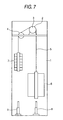
- Fig. 7 is an arrangement view showing an example of the conventional elevator.
- the winch 3, which has a drive sheave 2, and the deflector wheel 4 are arranged in an upper portion of the elevator way 1.
- the main rope 5 is wound round the drive sheave 2 and the deflector wheel 4.
- the cage 6 is hung from one end of the main rope 5, and the balance weight 7 is hung from the other end of the main rope 5.
- the drive sheave 2 is rotated, the cage 6 and the balance weight 7 are elevated like a draw well.
- the cage buffer 8 and the balance weight buffer 9 which are buffers for elevator use, are arranged in the bottom portion of the elevator way 1.
- an energy absorption type buffer or an energy storage type buffer for this buffer used for an elevator.
- collision energy is absorbed.
- a restoring means is provided and used together with the energy absorption type buffer.
- an oil-filled buffer is used for this energy absorption type buffer.
- This energy absorption type buffer is used for absorbing a relatively high intensity of collision energy when a high speed elevator is operated.
- the conventional oil-filled buffer includes: a cylindrical cylinder filled with hydraulic fluid which is vertically arranged in a bottom portion of the elevator way 1; a cylindrical plunger inserted into the cylinder being capable of reciprocating in the axial direction; an orifice hole formed in a bottom portion of the plunger; a long and slender conical member (control rod), the forward end portion of which is inserted into the orifice hole, vertically arranged in the bottom portion of the cylinder; and a restoring spring for elastically supporting and restoring the plunger.
- a buffer member is provided at the top portion of the plunger.
- the other conventional oil-filled buffer is composed in such a manner that a plurality of plungers, the diameters of which are formed so that they can be successively decreased small, are put into a cylinder filled with hydraulic fluid. Therefore, the plurality of plungers can be extended and contracted in the vertical direction by the hydraulic fluid. Further, return springs for returning the plurality of plungers to the initial positions are provided.
- this oil-filled buffer in which the plurality of plungers are arranged in the multiple stage as described above, as compared with the aforementioned oil-filled buffer composed of one plunger, a height of the oil-filled buffer, which is needed for obtaining the same stroke, can be reduced. Concerning this technique, for example, refer to Patent Document 3.
- the energy storage type buffer which is another buffer for elevator use, absorbs collision energy, and when this collision energy is released, the energy storage type buffer is restored to the initial state by itself.
- the energy storage type buffer is composed of an elastic body made of elastic material such as a spring or rubber. This energy storage type buffer is used for absorbing a relatively low intensity of collision energy in the case of a low speed elevator.
- An elastic body made of polyurethane can be compressed to 80% of the overall height, that is, a stroke of the buffer is 80% of the overall height. Therefore, at the time of collision with the cage 6 or the balance weight 7, the elastic body is compressed to 80% of the overall height so as to reduce a shock. After that, when the cage or the balance weight is lifted so that the load can be removed, the compressed elastic body is returned to the initial height, that is, the compressed elastic body is returned to the overall height. Concerning this technique, for example, refer to Non-patent Document 1.
- the buffer for elevator use is designed so that a speed of the cage 6 or the balance weight 7 can be reduced by a predetermined deceleration in a predetermined stroke when the cage 6 or the balance weight 7 collides with the buffer at the speed of 1.15 times as high as the rated speed. Therefore, when the rated speed is raised, a stroke of the buffer for elevator use is extended.
- the length of the plunger In the case where the rated speed is high, in the above conventional oil-filled buffer composed of one plunger, the length of the plunger must be longer than the stroke of the oil-filled buffer. Further, since the cylinder must receive the entering plunger, the length of cylinder must be long corresponding to the length of the plunger. Accordingly, the height of the oil-filled buffer is increased. When the height of the oil-filled buffer is increased as described above, the depth of the pit of the elevator way muse be increased. Accordingly, the following problems are encountered. Expenses needed for the construction work are raised. Further, since the oil-filled buffer is long, the working efficiency is deteriorated when the oil-filled buffer is brought in and installed.
- this oil-filled buffer is composed in such a manner that a plurality of plungers are put on each other and extended and contracted in the vertical direction via the hydraulic fluid. Therefore, the number of parts is increased and the manufacturing cost is raised.
- the stroke is 80% of the overall height. Therefore, while a predetermined stroke is being maintained, the height of the buffer can be reduced.
- the following problems may be encountered in this energy storage type buffer.
- EN code EN81-1: 1998) which is the European laws and ordinances
- the energy storage type buffer can be applied only to an elevator, the rated speed of which is not more than 60 m/min.
- the energy absorption type buffer can be applied to an elevator irrespective of the rated speed.
- the energy absorption type buffer is applied to an elevator, the rated speed of which exceeds 60 m/min, the above problems may be encountered.
- An object of the present invention is to provide a buffer for elevator use characterized in that: even when the rated speed of an elevator exceeds 60 m/ min, the height of the buffer can be reduced and it is unnecessary to increase the depth of a pit; and the structure can be simplified.
- an energy absorption type buffer and an energy storage type buffer are fixed to and combined with each other in series.
- the energy absorption type buffer and the energy storage type buffer are fixed to each other in series. Therefore, even when the rated speed of an elevator is high, it is possible to reduce the height of the buffer and the structure can be simplified.
- Fig. 1 is a view showing a buffer for elevator use of Embodiment 1 of the present invention.
- the energy storage type buffer 11a is fixed in series to an upper end portion of the oil-filled buffer 10a which is an energy absorption type buffer.
- the structure of the oil-filled buffer 10a will be explained as follows.
- the cylinder 14a filled with hydraulic fluid 13a is vertically arranged.
- the cylindrical plunger 15a capable of reciprocating in the axial direction is inserted into the cylinder 14a.
- the flange 16a is fixed to an upper end portion of the cylinder 14a.
- the spring receiver 17a is fixed to an upper end portion of the plunger 15a.
- the plunger 15a is provided with a bottom member 18a to close the bottom portion. At the center of the bottom member 18a, the orifice hole 19a is formed.
- the control rod 20a is vertically arranged on the mount 12a so that a forward end portion of the control rod 20a can be inserted into the orifice hole 19a.
- the control rod 20a is formed into a conical shape, the diameter of which is increased when it comes downward.
- the return spring 21a is provided which pushes and elastically supports the plunger 15a in the direction so that the plunger 15a can be protruded from the cylinder 14a.
- the oil-filled buffer 10a is composed as described above.
- the energy storage type buffer 11a is vertically arranged on the spring receiver 17a which is an upper end portion of this oil-filled buffer 10a. In this way, the buffer for elevator use is composed.
- the energy storage type buffer 11a is integrally made of rubber, for example, polyurethane. It is possible for the energy storage type buffer 11a to be compressed to 80% of the overall height. This compression is the same as the stroke of the energy storage type buffer 11a.
- the height of the energy storage type buffer 11a which is a body made of rubber, is returned from the compressed state to the initial extended state.
- the plunger 15a is pushed upward by a repulsion of the return spring 21a compressed, and hydraulic fluid 13a flows from the orifice hole 19a into the cylinder 14a. Therefore, the oil-filled buffer 10a is extended and returned to the initial state.
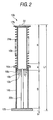
- Fig. 2 is a view showing the height of the conventional oil-filled buffer 10b composed of one plunger 15b
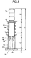
- Fig. 3 is a view showing the height of the buffer for elevator use of the present embodiment.
- the mount 12b, the hydraulic fluid 13b, the cylinder 14b, the plunger 15b, the flange 16b, the spring receiver 17b, the bottom portion member 18b of the plunger 15b, the orifice hole 19b, the control rod 29b and the return spring 21b are the same as the corresponding components shown in Fig. 1.
- the buffer member 22 is provided in an upper portion of the spring receiver 17b. In this case, operation is the same as that of the oil-filled buffer 10a shown in Fig. 1.
- the buffer for elevator use is designed so that the speed of the cage 6 or the balance weight 7 can be safely reduced at a predetermined deceleration when the cage 6 or the balance weight 7 collides with the buffer for elevator use at a speed which is 1.15 times as high as the rated speed.
- S is defined as a stroke of the buffer for elevator use. As shown in Fig. 2, the length of a portion in which the buffer material 22 conducts a stroke is S, and the length from the lower face of the bottom portion member 18b to the upper face of the mount 12b is the stroke of S.
- the elasticity characteristic is set by changing a shape of the energy storage type buffer 11a (for example, the length or the diameter) so that the stroke (the compression) of the energy storage type buffer 11a and the stroke of the oil-filled buffer 10a can be respectively 1/2 of the stroke S of the buffer, and resistance of hydraulic fluid is set by changing a gap formed between the orifice hole 19a of the oil-filled buffer 10a and the control rod 17a.
- the stroke (the compression) of the energy storage type buffer 11a and the stroke (the stroke of the oil-filled buffer 10a) of the spring receiver 17a are respectively S/2.
- the height of the overall buffer device can be downsized as compared with the conventional oil-filled buffer 10b which is composed of one plunger 15b. Due to the foregoing, even in the case where the elevator is operated at a high rated speed exceeding 60 m/min, it is unnecessary to increase the depth of the pit of the elevator way 1. Accordingly, the construction work cost can be decreased.
- the structure of the buffer device can be made simple.
- the buffer member 22 is provided in order to avoid the occurrence of collision between metals caused when the cage 6 or the balance weight 7 collides with the oil-filled buffer 10b.
- the height L2 of the buffer for elevator use is expressed by the following expression.
- L ⁇ 2 3 ⁇ S / 2 + a + b + c
- a difference between the height L1 of the conventional oil-filled buffer 10b and the height L2 of the buffer for elevator use of the present embodiment is approximately S/2 (half of the stroke). Accordingly, the height of the buffer for elevator use of the present embodiment can be reduced.
- the stroke (the compression) of the energy storage type buffer 11a and the stroke of the oil-filled buffer 10a are the same, that is, the stroke (the compression) of the energy storage type buffer 11a and the stroke of the oil-filled buffer 10a are respectively set at 1/2 of the stroke S of the buffer.
- the strokes may be set to be different from each other by changing the shape (for example, the length with the energy storage type buffer 11a made of rubber. Therefore, it is unnecessary to provide the buffer member 22.
- Fig. 2 is a view showing a buffer for elevator use of Embodiment 2 of the present invention.
- the energy storage type buffer 11c is fixed in series to the lower portion of the oil-filled buffer 10c.
- Like reference characters are used to indicate like parts in Figs. 1 and 4.
- the buffer member 23 is provided in an upper portion of the spring receiver 17a.
- the mount 24 is fixed. Since operation of this embodiment is the same as that of Embodiment 1, the explanations are omitted here.
- the buffer member 23 in order to avoid the occurrence of collision between metals caused when the cage 6 or the balance weight 7 collides with the oil-filled buffer 11c, the buffer member 23 must be provided.
- Fig. 5 is a view showing Embodiment 3 of the present invention.
- the restriction body 25 which restricts a stroke of the energy storage type buffer 11a at a predetermined value (for example, an allowable stroke) is provided on the spring receiver 17a.
- a predetermined value for example, an allowable stroke
- the restriction body 25 is formed into a cylindrical shape and inserted outside the energy storage type buffer 11a.
- the energy storage type buffer 11a When an abnormality is caused during the operation of an elevator and the cage 6 or the balance weight 7 collides with the buffer for elevator use, the energy storage type buffer 11a is compressed.
- the energy storage type buffer 11a can be compressed to 80% of the entire height. This compression is an allowable stroke. Therefore, when the energy storage type buffer 11a is compressed exceeding 80%, there is a possibility that the energy storage type buffer 11a is damaged.
- the elasticity characteristic of the energy storage type buffer 11a is set by determining its shape (for example, the length or the diameter) so that the compression of the energy storage type buffer 11a can be in an allowable stroke with respect to the assumed collision energy given when the elevator is operated at the specified speed.
- the restriction body 25 interferes with the cage 6 or the balance weight 7 in this case. Therefore, the energy storage type buffer 11a is not compressed exceeding the allowable stroke.
- the other motions are the same as those of Embodiment 1.
- the energy storage type buffer 11a is not compressed exceeding the allowable stroke. Therefore, the energy storage type buffer 11a is not damaged.
- the elasticity characteristic of the energy storage type buffer 11a must be set by determining its shape (for example, the length or the diameter) so that the compression of the energy storage type buffer 11a can be in an allowable stroke with respect to the assumed collision energy given when the elevator is operated at the specified speed.
- the restriction body 25 is formed into a cylindrical shape.
- the restriction body 25 may be formed into a rectangular shape, a columnar shape or any other shapes. Further, the number of the restriction body is not limited to one, that is, a plurality restriction bodies may be provided.
- the restriction body 25 is inserted outside the energy storage type buffer 11a. However, a cavity portion may be formed inside the energy storage type buffer 11a, and the restriction body 25 may be provided inside the cavity portion.
- Fig. 6 is a view showing Embodiment 4 of the present invention.
- the energy storage type buffer 11a and the oil-filled buffer 10a can be divided from each other.
- the attaching plate 26 is fixed to a lower face of the energy storage type buffer 11a.
- This attaching plate 26 is fixed to the spring receiver 17a by the bolts 27.
- like parts are used to indicate like parts in Figs. 1 and 6. Operation is the same as that of Embodiment 1.
- the energy storage type buffer 11a is made of rubber such as polyurethane
- the elasticity characteristic of rubber changes with age. Therefore, it is necessary to periodically replace the energy storage type buffer 11a made of rubber with a new one.
- the energy storage type buffer 11a and the oil-filled buffer 10a can be divided from each other. Therefore, it is unnecessary to replace both the energy storage type buffer 11a and the oil-filled buffer 10a, that is, only the energy storage type buffer 11a can be replaced. Accordingly, the expenses necessary for the replacement can be reduced.
- the energy storage type buffer is composed of a body made of rubber, the compression of which is 80% of the overall height.
- the energy storage type buffer may be composed of a body made of rubber, the compression of which is not less than 80% of the overall height or not more than 80% of the overall height.
- a cylindrical coil spring or a conical coil spring may be used. Especially when the conical coil spring is used, the height can be reduced as compared with the cylindrical coil spring at the time of compression.
- the buffer for elevator use of the present invention is suitably used for safely stopping the cage 6 or the balance weight 7 while a collision shock is being reduced when the cage 6 or the balance weight 7 descends passing the lowest floor.
Landscapes
- Maintenance And Inspection Apparatuses For Elevators (AREA)
- Vibration Dampers (AREA)
- Fluid-Damping Devices (AREA)
- Vibration Prevention Devices (AREA)
Abstract
Description
- The present invention relates to a buffer for elevator use, which is arranged in a bottom portion of an elevator way, for lightening a shock and stopping a cage or a balance weight of the elevator when the cage or the balance weight has been lowered and passed the lowest floor.
- Fig. 7 is an arrangement view showing an example of the conventional elevator. In Fig. 7, the
winch 3, which has adrive sheave 2, and thedeflector wheel 4 are arranged in an upper portion of the elevator way 1. Themain rope 5 is wound round thedrive sheave 2 and thedeflector wheel 4. Thecage 6 is hung from one end of themain rope 5, and thebalance weight 7 is hung from the other end of themain rope 5. When thedrive sheave 2 is rotated, thecage 6 and thebalance weight 7 are elevated like a draw well. - When some problems are caused in the elevator, there is a possibility that the
cage 6 or thebalance weight 7 passes the lowest floor and further descends. Therefore, even when the problems are caused in the elevator, in order to lighten a shock caused between thecage 6 or thebalance weight 7 and the bottom portion (pit) of the elevator way 1 and to stop thecage 6 safely, thecage buffer 8 and thebalance weight buffer 9, which are buffers for elevator use, are arranged in the bottom portion of the elevator way 1. - Conventionally, there is provided an energy absorption type buffer or an energy storage type buffer for this buffer used for an elevator. According to the energy absorption type buffer, collision energy is absorbed. When this collision energy is released, it is impossible for the energy absorption type buffer to be restored to the initial state by itself. Therefore, a restoring means is provided and used together with the energy absorption type buffer. For example, an oil-filled buffer is used for this energy absorption type buffer. This energy absorption type buffer is used for absorbing a relatively high intensity of collision energy when a high speed elevator is operated.
- The conventional oil-filled buffer includes: a cylindrical cylinder filled with hydraulic fluid which is vertically arranged in a bottom portion of the elevator way 1; a cylindrical plunger inserted into the cylinder being capable of reciprocating in the axial direction; an orifice hole formed in a bottom portion of the plunger; a long and slender conical member (control rod), the forward end portion of which is inserted into the orifice hole, vertically arranged in the bottom portion of the cylinder; and a restoring spring for elastically supporting and restoring the plunger.
- In order to reduce a shock and noise generated when the
cage 6 or thebalance weight 7 collides with the oil-filled buffer, a buffer member is provided at the top portion of the plunger. - Assume a case in which some problems are caused while the elevator is running and the
cage 6 or thebalance weight 7 collides with the buffer member located in an upper portion of the oil-filled buffer. Then, the plunger is pushed downward resisting an elastic force of the return spring. Therefore, hydraulic fluid in the cylinder is pushed downward by a lower face of the plunger and flows out from the orifice hole into the plunger. In this case, since the control rod is tapered, that is, since the diameter of the control rod is gradually increased when it comes downward, as the plunger descends, an area of the orifice hole, in which the hydraulic fluid flows, is decreased. Therefore, resistance given to the hydraulic fluid is gradually increased and the descending speed is decreased, so that the shock can be reduced. After that, when thecage 6 or thebalance weight 7 is lifted and the load is removed, the plunger is pushed and returned to the initial position by a repulsion of the compressed return spring. Concerning this technique, for example, refer toPatent Documents 1 and 2. - The other conventional oil-filled buffer is composed in such a manner that a plurality of plungers, the diameters of which are formed so that they can be successively decreased small, are put into a cylinder filled with hydraulic fluid. Therefore, the plurality of plungers can be extended and contracted in the vertical direction by the hydraulic fluid. Further, return springs for returning the plurality of plungers to the initial positions are provided. In this oil-filled buffer in which the plurality of plungers are arranged in the multiple stage as described above, as compared with the aforementioned oil-filled buffer composed of one plunger, a height of the oil-filled buffer, which is needed for obtaining the same stroke, can be reduced. Concerning this technique, for example, refer to
Patent Document 3. - The above explanations are made into the oil-filled buffer which is an energy absorption type buffer. However, the energy storage type buffer, which is another buffer for elevator use, absorbs collision energy, and when this collision energy is released, the energy storage type buffer is restored to the initial state by itself. For example, the energy storage type buffer is composed of an elastic body made of elastic material such as a spring or rubber. This energy storage type buffer is used for absorbing a relatively low intensity of collision energy in the case of a low speed elevator. An elastic body made of polyurethane can be compressed to 80% of the overall height, that is, a stroke of the buffer is 80% of the overall height. Therefore, at the time of collision with the
cage 6 or thebalance weight 7, the elastic body is compressed to 80% of the overall height so as to reduce a shock. After that, when the cage or the balance weight is lifted so that the load can be removed, the compressed elastic body is returned to the initial height, that is, the compressed elastic body is returned to the overall height. Concerning this technique, for example, refer to Non-patent Document 1. -
- Patent Document 1: Official gazette of
JP-A-8-108984 pages - Patent Document 2: Official gazette of
JP-A-4-217577 pages 4 to 6, Fig. 1) - Patent Document 3: Official gazette of
JP-A-4-217577 pages 2 to 5, Fig. 1) - Non-patent Document 1: Catalog of Elastogran Co. "Cellasto A celluar polyurethane elastomer" page 1
- The buffer for elevator use is designed so that a speed of the
cage 6 or thebalance weight 7 can be reduced by a predetermined deceleration in a predetermined stroke when thecage 6 or thebalance weight 7 collides with the buffer at the speed of 1.15 times as high as the rated speed. Therefore, when the rated speed is raised, a stroke of the buffer for elevator use is extended. - In the case where the rated speed is high, in the above conventional oil-filled buffer composed of one plunger, the length of the plunger must be longer than the stroke of the oil-filled buffer. Further, since the cylinder must receive the entering plunger, the length of cylinder must be long corresponding to the length of the plunger. Accordingly, the height of the oil-filled buffer is increased. When the height of the oil-filled buffer is increased as described above, the depth of the pit of the elevator way muse be increased. Accordingly, the following problems are encountered. Expenses needed for the construction work are raised. Further, since the oil-filled buffer is long, the working efficiency is deteriorated when the oil-filled buffer is brought in and installed.
- On the other hand, in the oil-filled buffer, the plunger of which is composed by a multiple stage, with respect to the oil-filled buffer composed of one plunger, while a predetermined stroke is being maintained, the height of the oil-filled buffer can be reduced. Therefore, the problems described above are not caused. However, this oil-filled buffer is composed in such a manner that a plurality of plungers are put on each other and extended and contracted in the vertical direction via the hydraulic fluid. Therefore, the number of parts is increased and the manufacturing cost is raised.
- As described above, in the energy storage type buffer, the stroke is 80% of the overall height. Therefore, while a predetermined stroke is being maintained, the height of the buffer can be reduced. However, the following problems may be encountered in this energy storage type buffer. For example, according to EN code (EN81-1: 1998) which is the European laws and ordinances, the energy storage type buffer can be applied only to an elevator, the rated speed of which is not more than 60 m/min. In this connection, according to EN code, the energy absorption type buffer can be applied to an elevator irrespective of the rated speed. However, when the energy absorption type buffer is applied to an elevator, the rated speed of which exceeds 60 m/min, the above problems may be encountered.
- The present invention has been accomplished to solve the above problems. An object of the present invention is to provide a buffer for elevator use characterized in that: even when the rated speed of an elevator exceeds 60 m/ min, the height of the buffer can be reduced and it is unnecessary to increase the depth of a pit; and the structure can be simplified.
- In the buffer for elevator use of the present invention, an energy absorption type buffer and an energy storage type buffer are fixed to and combined with each other in series.
- According to the present invention, the energy absorption type buffer and the energy storage type buffer are fixed to each other in series. Therefore, even when the rated speed of an elevator is high, it is possible to reduce the height of the buffer and the structure can be simplified.
-
- [Fig. 1] A view showing a buffer for elevator use in Embodiment 1 of the present invention.
- [Fig. 2] A view showing a height of the conventional oil-filled buffer.
- [Fig. 3] A view showing a height of the buffer for elevator use of Embodiment 1 of the present invention.
- [Fig. 4] A view showing a buffer for elevator use in
Embodiment 2 of the present invention. - [Fig. 5] A view showing a buffer for elevator use in
Embodiment 3 of the present invention. - [Fig. 6] A view showing a buffer for elevator use in
Embodiment 4 of the present invention. - [Fig. 7] An arrangement view showing an example of the conventional elevator.
-
- 1
- Elevator way
- 2
- Drive sheave
- 3
- Winch
- 4
- Deflector wheel
- 5
- Main rope
- 6
- Cage
- 7
- Balance weight
- 8
- Cage buffer
- 9
- Balance weight buffer
- 10a, 10b, 10c
- Oil-filled buffer
- 11a, 11c
- Energy storage type buffer
- 12a, 12b
- Mount
- 13a, 13b
- Hydraulic fluid
- 14a, 14b
- Cylinder
- 15a, 15b
- Plunger
- 16a, 16b
- Flange
- 17a, 17b
- Spring receiver
- 18a, 18b
- Bottom portion member
- 19a, 19b
- Orifice hole
- 20a, 20b
- Control rod
- 21a, 21b
- Return spring
- 22, 23
- Buffer material
- 24
- Mount
- 25
- Restriction body
- 26
- Attaching plate
- 27
- Bolt
- Referring to the drawings, the preferred embodiments of the present invention will be explained below.
- Fig. 1 is a view showing a buffer for elevator use of Embodiment 1 of the present invention. In Fig. 1, the energy
storage type buffer 11a is fixed in series to an upper end portion of the oil-filledbuffer 10a which is an energy absorption type buffer. Next, the structure of the oil-filledbuffer 10a will be explained as follows. On themount 12a, thecylinder 14a filled withhydraulic fluid 13a is vertically arranged. Thecylindrical plunger 15a capable of reciprocating in the axial direction is inserted into thecylinder 14a. Theflange 16a is fixed to an upper end portion of thecylinder 14a. Thespring receiver 17a is fixed to an upper end portion of theplunger 15a. - The
plunger 15a is provided with abottom member 18a to close the bottom portion. At the center of thebottom member 18a, theorifice hole 19a is formed. Thecontrol rod 20a is vertically arranged on themount 12a so that a forward end portion of thecontrol rod 20a can be inserted into theorifice hole 19a. Thecontrol rod 20a is formed into a conical shape, the diameter of which is increased when it comes downward. - As restoration means for restoring the
plunger 15a to the initial position after theplunger 15a has been pushed and lowered, between theflange 16a and thespring receiver 17a, thereturn spring 21a is provided which pushes and elastically supports theplunger 15a in the direction so that theplunger 15a can be protruded from thecylinder 14a. - The oil-filled
buffer 10a is composed as described above. The energystorage type buffer 11a is vertically arranged on thespring receiver 17a which is an upper end portion of this oil-filledbuffer 10a. In this way, the buffer for elevator use is composed. The energystorage type buffer 11a is integrally made of rubber, for example, polyurethane. It is possible for the energystorage type buffer 11a to be compressed to 80% of the overall height. This compression is the same as the stroke of the energystorage type buffer 11a. - Next, operation will be explained as follows. While the elevator is normally running, the oil-filled
buffer 10a and the energystorage type buffer 11a, which compose the buffer for elevator use, are respectively extended as shown in Fig. 1. Assume a case in which an abnormality is caused while the elevator is running and thecage 6 or thebalance weight 7 collides with the buffer for elevator use. At this time, thecage 6 or thebalance weight 7 collides with the energystorage type buffer 11a. Therefore, the energystorage type buffer 11a is compressed and reduces the shock given to it. - On the other hand, in the oil-filled
buffer 10a, together with the compression of the energystorage type buffer 11a, theplunger 15a of the oil-filledbuffer 10a is pushed down, resisting an elastic force generated by thereturn spring 21a. Therefore,hydraulic fluid 13a in thecylinder 14a is pushed by thebottom portion member 18a of theplunger 15a and flows out from theorifice hole 19a into theplunger 15a. Since thecontrol rod 20a is tapered in such a manner that the diameter of thecontrol rod 20a is gradually increased as it comes to the lower portion, when theplunger 15a is lowered, an area of theorifice hole 19a, in which hydraulic 13a fluid passes, is reduced. Accordingly, resistance given tohydraulic fluid 13a is gradually increased and the lowering speed of theplunger 15a is decreased, so that the shock can be reduced. - After that, when the
cage 6 or thebalance weight 7 is lifted and the load is removed from the buffer for elevator use, the height of the energystorage type buffer 11a, which is a body made of rubber, is returned from the compressed state to the initial extended state. On the other hand, in the oil-filledbuffer 10a, theplunger 15a is pushed upward by a repulsion of thereturn spring 21a compressed, andhydraulic fluid 13a flows from theorifice hole 19a into thecylinder 14a. Therefore, the oil-filledbuffer 10a is extended and returned to the initial state. - Next, explanations will be made for the height of the buffer for elevator use of this embodiment. Fig. 2 is a view showing the height of the conventional oil-filled
buffer 10b composed of oneplunger 15b, and Fig. 3 is a view showing the height of the buffer for elevator use of the present embodiment. - In Fig. 2, the
mount 12b, thehydraulic fluid 13b, thecylinder 14b, theplunger 15b, theflange 16b, thespring receiver 17b, thebottom portion member 18b of theplunger 15b, theorifice hole 19b, the control rod 29b and thereturn spring 21b are the same as the corresponding components shown in Fig. 1. In order to avoid the occurrence of collision between metals caused when thecage 6 or thebalance weight 7 collides with the oil-filledbuffer 10b, thebuffer member 22 is provided in an upper portion of thespring receiver 17b. In this case, operation is the same as that of the oil-filledbuffer 10a shown in Fig. 1. - The buffer for elevator use is designed so that the speed of the
cage 6 or thebalance weight 7 can be safely reduced at a predetermined deceleration when thecage 6 or thebalance weight 7 collides with the buffer for elevator use at a speed which is 1.15 times as high as the rated speed. In this case, S is defined as a stroke of the buffer for elevator use. As shown in Fig. 2, the length of a portion in which thebuffer material 22 conducts a stroke is S, and the length from the lower face of thebottom portion member 18b to the upper face of themount 12b is the stroke of S. When the length from the lower end of the stroke portion of thebuffer material 22 to the lower face of thebottom portion member 18b of theplunger 15b is defined as "a" and the thickness of themount 12b is "b", the height L1 of the conventional oil-filledbuffer 10b is expressed by the following expression.
- On the other hand, concerning the buffer for elevator use of the present embodiment, as shown in Fig. 3, the elasticity characteristic is set by changing a shape of the energy
storage type buffer 11a (for example, the length or the diameter) so that the stroke (the compression) of the energystorage type buffer 11a and the stroke of the oil-filledbuffer 10a can be respectively 1/2 of the stroke S of the buffer, and resistance of hydraulic fluid is set by changing a gap formed between theorifice hole 19a of the oil-filledbuffer 10a and thecontrol rod 17a. In this case, as shown in Fig. 3, the stroke (the compression) of the energystorage type buffer 11a and the stroke (the stroke of the oil-filledbuffer 10a) of thespring receiver 17a are respectively S/2. When "a" is defined as the length from the lower end of the stroke portion of thespring receiver 17a to the lower face of thebottom portion member 18a of theplunger 15a and "b" is defined as the thickness of themount 12a and "c" is defined as the height or the diameter) of the energystorage type buffer 11a and by changing the gap between theorifice hole 19a of the oil-filledbuffer 10a and thecontrol rod 17a. Especially when the stroke (the compression) of the energystorage type buffer 11a is increased, it becomes possible to reduce the height of the buffer for elevator use. - As described above, when the energy
storage type buffer 11a of a simple structure is fixed in series to an upper end portion of the oil-filledbuffer 10a which is an energy absorption type buffer, the height of the overall buffer device can be downsized as compared with the conventional oil-filledbuffer 10b which is composed of oneplunger 15b. Due to the foregoing, even in the case where the elevator is operated at a high rated speed exceeding 60 m/min, it is unnecessary to increase the depth of the pit of the elevator way 1. Accordingly, the construction work cost can be decreased. - Since one of the buffers is composed of the energy
storage type buffer 11a, the structure of the buffer device can be made simple. In the conventional oil-filledbuffer 10b, in order to avoid the occurrence of collision between metals caused when thecage 6 or thebalance weight 7 collides with the oil-filledbuffer 10b, thebuffer member 22 is provided. However, in the present embodiment, thecage 6 or thebalance weight 7 collides of the energystorage type buffer 11a at the time of compression, the height L2 of the buffer for elevator use is expressed by the following expression.
storage type buffer 11a is compressed to 80% of the overall height as described before, the height "c" at the time of compression can be expressed as follows.
- As described above, a difference between the height L1 of the conventional oil-filled
buffer 10b and the height L2 of the buffer for elevator use of the present embodiment is approximately S/2 (half of the stroke). Accordingly, the height of the buffer for elevator use of the present embodiment can be reduced. - As described above, the stroke (the compression) of the energy
storage type buffer 11a and the stroke of the oil-filledbuffer 10a are the same, that is, the stroke (the compression) of the energystorage type buffer 11a and the stroke of the oil-filledbuffer 10a are respectively set at 1/2 of the stroke S of the buffer. However, the strokes may be set to be different from each other by changing the shape (for example, the length with the energystorage type buffer 11a made of rubber. Therefore, it is unnecessary to provide thebuffer member 22. - Fig. 2 is a view showing a buffer for elevator use of
Embodiment 2 of the present invention. In this embodiment, with respect to Embodiment 1, the energystorage type buffer 11c is fixed in series to the lower portion of the oil-filledbuffer 10c. Like reference characters are used to indicate like parts in Figs. 1 and 4. In this embodiment, in order to avoid the occurrence of collision between metals caused when thecage 6 or thebalance weight 7 collides with the oil-filledbuffer 11c, thebuffer member 23 is provided in an upper portion of thespring receiver 17a. In the bottom portion of the energystorage type buffer 11c, themount 24 is fixed. Since operation of this embodiment is the same as that of Embodiment 1, the explanations are omitted here. - Even in the structure of this embodiment, it is possible to provide the same effect as that of Embodiment 1. However, with respect to Embodiment 1, in order to avoid the occurrence of collision between metals caused when the
cage 6 or thebalance weight 7 collides with the oil-filledbuffer 11c, thebuffer member 23 must be provided. - Fig. 5 is a
view showing Embodiment 3 of the present invention. In this embodiment, with respect to Embodiment 1, therestriction body 25, which restricts a stroke of the energystorage type buffer 11a at a predetermined value (for example, an allowable stroke), is provided on thespring receiver 17a. Like reference characters are used to indicate like parts in Figs. 1 and 5. In this connection, therestriction body 25 is formed into a cylindrical shape and inserted outside the energystorage type buffer 11a. - When an abnormality is caused during the operation of an elevator and the
cage 6 or thebalance weight 7 collides with the buffer for elevator use, the energystorage type buffer 11a is compressed. The energystorage type buffer 11a can be compressed to 80% of the entire height. This compression is an allowable stroke. Therefore, when the energystorage type buffer 11a is compressed exceeding 80%, there is a possibility that the energystorage type buffer 11a is damaged. The elasticity characteristic of the energystorage type buffer 11a is set by determining its shape (for example, the length or the diameter) so that the compression of the energystorage type buffer 11a can be in an allowable stroke with respect to the assumed collision energy given when the elevator is operated at the specified speed. However, when an intensity of the collision energy exceeds an intensity of the previously assumed energy, the compression exceeds the allowable stroke. According to the present embodiment, therestriction body 25 interferes with thecage 6 or thebalance weight 7 in this case. Therefore, the energystorage type buffer 11a is not compressed exceeding the allowable stroke. The other motions are the same as those of Embodiment 1. - As described above, even when an intensity of collision energy is high, since the stroke of the energy
storage type buffer 11a is restricted by therestriction body 25, the energystorage type buffer 11a is not compressed exceeding the allowable stroke. Therefore, the energystorage type buffer 11a is not damaged. The elasticity characteristic of the energystorage type buffer 11a must be set by determining its shape (for example, the length or the diameter) so that the compression of the energystorage type buffer 11a can be in an allowable stroke with respect to the assumed collision energy given when the elevator is operated at the specified speed. However, it is substantially difficult for the elasticity characteristic to be set with respect to all the specified speeds, because it is too complicated. In this case, when therestriction body 25 is provided, the stroke of the energystorage type buffer 11a can be easily set. - In this connection, according to the present embodiment, the
restriction body 25 is formed into a cylindrical shape. However, the present invention is not limited to the above specific embodiment. Therestriction body 25 may be formed into a rectangular shape, a columnar shape or any other shapes. Further, the number of the restriction body is not limited to one, that is, a plurality restriction bodies may be provided. In the present embodiment, therestriction body 25 is inserted outside the energystorage type buffer 11a. However, a cavity portion may be formed inside the energystorage type buffer 11a, and therestriction body 25 may be provided inside the cavity portion. - Fig. 6 is a
view showing Embodiment 4 of the present invention. In this embodiment, with respect to Embodiment 1, the energystorage type buffer 11a and the oil-filledbuffer 10a can be divided from each other. In Fig. 6, the attachingplate 26 is fixed to a lower face of the energystorage type buffer 11a. This attachingplate 26 is fixed to thespring receiver 17a by thebolts 27. Except for the above, like parts are used to indicate like parts in Figs. 1 and 6. Operation is the same as that of Embodiment 1. - In the case where the energy
storage type buffer 11a is made of rubber such as polyurethane, generally speaking, the elasticity characteristic of rubber changes with age. Therefore, it is necessary to periodically replace the energystorage type buffer 11a made of rubber with a new one. In this case, according to the present embodiment, the energystorage type buffer 11a and the oil-filledbuffer 10a can be divided from each other. Therefore, it is unnecessary to replace both the energystorage type buffer 11a and the oil-filledbuffer 10a, that is, only the energystorage type buffer 11a can be replaced. Accordingly, the expenses necessary for the replacement can be reduced. - In Embodiments 1 to 4 described above, the energy storage type buffer is composed of a body made of rubber, the compression of which is 80% of the overall height. However, the present invention is not limited to the above specific embodiment. The energy storage type buffer may be composed of a body made of rubber, the compression of which is not less than 80% of the overall height or not more than 80% of the overall height. Instead of the rubber body, a cylindrical coil spring or a conical coil spring may be used. Especially when the conical coil spring is used, the height can be reduced as compared with the cylindrical coil spring at the time of compression.
- As described above, the buffer for elevator use of the present invention is suitably used for safely stopping the
cage 6 or thebalance weight 7 while a collision shock is being reduced when thecage 6 or thebalance weight 7 descends passing the lowest floor.
Claims (5)
- A buffer for elevator use, which is arranged in a bottom portion of an elevator way and under a cage or a balance weight, for reducing a shock caused when the cage or the balance weight collides with the buffer for elevator use, comprising: an energy absorption type buffer; and an energy storage type buffer fixed in series to this energy absorption type buffer.
- The buffer for elevator use according to claim 1, wherein the energy storage type buffer is arranged in series to an upper portion of the energy absorption type buffer.
- The buffer for elevator use according to claim 1 or 2, wherein a restriction body for restricting a stroke of the energy storage type buffer is arranged in the energy storage type buffer.
- The buffer for elevator use according to one of claims 1 to 3, wherein the energy storage type buffer and the energy absorption type buffer are capable of being divided from each other.
- The buffer for elevator use according to one of claims 1 to 4, wherein the energy storage type buffer is composed of a rubber body.
Applications Claiming Priority (1)
| Application Number | Priority Date | Filing Date | Title |
|---|---|---|---|
| PCT/JP2004/013731 WO2006033135A1 (en) | 2004-09-21 | 2004-09-21 | Shock absorbing device for elevator |
Publications (2)
| Publication Number | Publication Date |
|---|---|
| EP1792866A1 true EP1792866A1 (en) | 2007-06-06 |
| EP1792866A4 EP1792866A4 (en) | 2012-01-18 |
Family
ID=36089902
Family Applications (1)
| Application Number | Title | Priority Date | Filing Date |
|---|---|---|---|
| EP04787914A Withdrawn EP1792866A4 (en) | 2004-09-21 | 2004-09-21 | SHOCK ABSORBER DEVICE FOR ELEVATOR |
Country Status (5)
| Country | Link |
|---|---|
| EP (1) | EP1792866A4 (en) |
| JP (1) | JPWO2006033135A1 (en) |
| KR (1) | KR20070032937A (en) |
| CN (1) | CN1922091A (en) |
| WO (1) | WO2006033135A1 (en) |
Cited By (2)
| Publication number | Priority date | Publication date | Assignee | Title |
|---|---|---|---|---|
| WO2010019145A1 (en) * | 2008-08-14 | 2010-02-18 | Otis Elevator Company | Inspection device and method for deformable elevator buffers |
| US20100307871A1 (en) * | 2007-08-31 | 2010-12-09 | Mitsubishi Electric Corporation | Oil buffer for an elevator |
Families Citing this family (10)
| Publication number | Priority date | Publication date | Assignee | Title |
|---|---|---|---|---|
| ES2432518T3 (en) * | 2007-11-30 | 2013-12-04 | Otis Elevator Company | Passive magnetic elevator car stabilizer |
| CN103708319A (en) * | 2012-09-30 | 2014-04-09 | 凌怀宇 | Suspension type elevator buffer |
| CN103241612A (en) * | 2013-05-20 | 2013-08-14 | 苏州新达电扶梯部件有限公司 | Double-shaft shock absorption press rod |
| CN104444695B (en) * | 2014-12-13 | 2017-08-25 | 重庆和航科技股份有限公司 | The buffer system of the progressive damping force of elevator adaptability |
| CN108190683B (en) * | 2017-12-09 | 2019-07-19 | 上海中菱电梯有限公司 | A kind of elevator multi-stage buffer |
| CN108116960A (en) * | 2017-12-19 | 2018-06-05 | 苏州市远极智能科技有限公司 | A kind of elevator |
| CN109319626A (en) * | 2018-11-05 | 2019-02-12 | 广州广日电梯工业有限公司 | A kind of novel elevator hydraulic bjuffer |
| WO2020194573A1 (en) * | 2019-03-27 | 2020-10-01 | 三菱電機株式会社 | Spring buffer for elevator |
| CN111397827A (en) * | 2020-04-26 | 2020-07-10 | 中国工程物理研究院总体工程研究所 | Guide drop test system and method |
| EP4201862A1 (en) * | 2021-12-24 | 2023-06-28 | Otis Elevator Company | Buffer device |
Family Cites Families (10)
| Publication number | Priority date | Publication date | Assignee | Title |
|---|---|---|---|---|
| JPS6019568U (en) * | 1983-07-18 | 1985-02-09 | 株式会社東芝 | elevator shock absorber |
| JPS60137766U (en) * | 1984-12-20 | 1985-09-12 | 三菱電機株式会社 | Elevator oil-filled buffer |
| JPH04217577A (en) | 1990-12-20 | 1992-08-07 | Mitsubishi Electric Corp | Oil-immersed buffer for elevator |
| JPH06115848A (en) * | 1992-10-01 | 1994-04-26 | Toshiba Corp | Elevator buffer |
| JPH08108984A (en) | 1994-10-12 | 1996-04-30 | Hitachi Ltd | Oil buffer for elevator |
| JP2000302353A (en) * | 1999-04-22 | 2000-10-31 | Toshiba Corp | Elevator spring shock absorber |
| JP2001151435A (en) * | 1999-11-25 | 2001-06-05 | Hitachi Ltd | Elevator shock absorber and elevator |
| JP3619110B2 (en) * | 2000-03-01 | 2005-02-09 | 株式会社日立製作所 | Elevator shock absorber |
| JP4301837B2 (en) * | 2002-05-21 | 2009-07-22 | 三菱電機株式会社 | Elevator shock absorber |
| JP2004018233A (en) * | 2002-06-19 | 2004-01-22 | Hitachi Ltd | Elevator shock absorber |
-
2004
- 2004-09-21 JP JP2006536271A patent/JPWO2006033135A1/en active Pending
- 2004-09-21 CN CNA2004800422116A patent/CN1922091A/en active Pending
- 2004-09-21 WO PCT/JP2004/013731 patent/WO2006033135A1/en not_active Ceased
- 2004-09-21 KR KR1020067017170A patent/KR20070032937A/en not_active Ceased
- 2004-09-21 EP EP04787914A patent/EP1792866A4/en not_active Withdrawn
Cited By (3)
| Publication number | Priority date | Publication date | Assignee | Title |
|---|---|---|---|---|
| US20100307871A1 (en) * | 2007-08-31 | 2010-12-09 | Mitsubishi Electric Corporation | Oil buffer for an elevator |
| US8360210B2 (en) * | 2007-08-31 | 2013-01-29 | Mitsubishi Electric Corporation | Oil buffer for an elevator |
| WO2010019145A1 (en) * | 2008-08-14 | 2010-02-18 | Otis Elevator Company | Inspection device and method for deformable elevator buffers |
Also Published As
| Publication number | Publication date |
|---|---|
| WO2006033135A1 (en) | 2006-03-30 |
| JPWO2006033135A1 (en) | 2008-05-15 |
| EP1792866A4 (en) | 2012-01-18 |
| KR20070032937A (en) | 2007-03-23 |
| CN1922091A (en) | 2007-02-28 |
Similar Documents
| Publication | Publication Date | Title |
|---|---|---|
| EP1792866A1 (en) | Shock absorbing device for elevator | |
| US7287626B2 (en) | Buffer device for elevator | |
| JP5081066B2 (en) | Hydraulic shock absorber for elevator | |
| US8047335B2 (en) | Shock absorbing hitch | |
| JPWO2009028100A1 (en) | Elevator hydraulic shock absorber | |
| JP3619110B2 (en) | Elevator shock absorber | |
| JP5368289B2 (en) | Elevator equipment | |
| EP2088111A1 (en) | Buffer of elevator | |
| JPH0664861A (en) | Pit buffer assembly for elevator system | |
| CN1668523A (en) | Conical Spring Buffers for Elevators | |
| JP2011073823A (en) | Elevator buffer | |
| JP2001241506A (en) | Shock absorber | |
| EP1928776B1 (en) | Frangible buffer for an elevator system with multiple cars in a hoistway | |
| CN213415238U (en) | Belt feeder straining device and mounting structure of belt feeder | |
| CN103274335B (en) | Straight top type loading lifting table | |
| KR101200506B1 (en) | Limit switch apparatus for oil-filled shock absorber | |
| US20060225967A1 (en) | Conical spring buffer for an elevator | |
| CN113879937B (en) | Elevator buffer and working method thereof | |
| CN202130956U (en) | Over-winding and over-relaxation buffering cage supporting device through deformation of steel wire rope | |
| CN120622268A (en) | Novel deceleration elevator pit buffering device | |
| KR100358497B1 (en) | Device to reduce shock when hydraulic jack starts or stops | |
| JP3178109U (en) | Elevator system | |
| JP2004018233A (en) | Elevator shock absorber | |
| JP5436340B2 (en) | Elevator safety equipment | |
| KR101147825B1 (en) | Oil-filled shock absorber for elevator |
Legal Events
| Date | Code | Title | Description |
|---|---|---|---|
| PUAI | Public reference made under article 153(3) epc to a published international application that has entered the european phase |
Free format text: ORIGINAL CODE: 0009012 |
|
| 17P | Request for examination filed |
Effective date: 20060825 |
|
| AK | Designated contracting states |
Kind code of ref document: A1 Designated state(s): DE |
|
| RAP1 | Party data changed (applicant data changed or rights of an application transferred) |
Owner name: MITSUBISHI ELECTRIC CORPORATION |
|
| DAX | Request for extension of the european patent (deleted) | ||
| RBV | Designated contracting states (corrected) |
Designated state(s): DE |
|
| A4 | Supplementary search report drawn up and despatched |
Effective date: 20111216 |
|
| RIC1 | Information provided on ipc code assigned before grant |
Ipc: B66B 5/28 20060101AFI20111212BHEP |
|
| 17Q | First examination report despatched |
Effective date: 20120510 |
|
| STAA | Information on the status of an ep patent application or granted ep patent |
Free format text: STATUS: THE APPLICATION IS DEEMED TO BE WITHDRAWN |
|
| 18D | Application deemed to be withdrawn |
Effective date: 20150401 |