EP1792719A2 - Apparatus and method of manufacturing reduced gauge tire ply - Google Patents
Apparatus and method of manufacturing reduced gauge tire ply Download PDFInfo
- Publication number
- EP1792719A2 EP1792719A2 EP06124733A EP06124733A EP1792719A2 EP 1792719 A2 EP1792719 A2 EP 1792719A2 EP 06124733 A EP06124733 A EP 06124733A EP 06124733 A EP06124733 A EP 06124733A EP 1792719 A2 EP1792719 A2 EP 1792719A2
- Authority
- EP
- European Patent Office
- Prior art keywords
- ply
- layer
- cords
- rubber
- cord
- Prior art date
- Legal status (The legal status is an assumption and is not a legal conclusion. Google has not performed a legal analysis and makes no representation as to the accuracy of the status listed.)
- Withdrawn
Links
Images





Classifications
-
- B—PERFORMING OPERATIONS; TRANSPORTING
- B29—WORKING OF PLASTICS; WORKING OF SUBSTANCES IN A PLASTIC STATE IN GENERAL
- B29D—PRODUCING PARTICULAR ARTICLES FROM PLASTICS OR FROM SUBSTANCES IN A PLASTIC STATE
- B29D30/00—Producing pneumatic or solid tyres or parts thereof
- B29D30/06—Pneumatic tyres or parts thereof (e.g. produced by casting, moulding, compression moulding, injection moulding, centrifugal casting)
- B29D30/38—Textile inserts, e.g. cord or canvas layers, for tyres; Treatment of inserts prior to building the tyre
-
- B—PERFORMING OPERATIONS; TRANSPORTING
- B29—WORKING OF PLASTICS; WORKING OF SUBSTANCES IN A PLASTIC STATE IN GENERAL
- B29C—SHAPING OR JOINING OF PLASTICS; SHAPING OF MATERIAL IN A PLASTIC STATE, NOT OTHERWISE PROVIDED FOR; AFTER-TREATMENT OF THE SHAPED PRODUCTS, e.g. REPAIRING
- B29C43/00—Compression moulding, i.e. applying external pressure to flow the moulding material; Apparatus therefor
- B29C43/22—Compression moulding, i.e. applying external pressure to flow the moulding material; Apparatus therefor of articles of indefinite length
- B29C43/28—Compression moulding, i.e. applying external pressure to flow the moulding material; Apparatus therefor of articles of indefinite length incorporating preformed parts or layers, e.g. compression moulding around inserts or for coating articles
-
- B—PERFORMING OPERATIONS; TRANSPORTING
- B29—WORKING OF PLASTICS; WORKING OF SUBSTANCES IN A PLASTIC STATE IN GENERAL
- B29C—SHAPING OR JOINING OF PLASTICS; SHAPING OF MATERIAL IN A PLASTIC STATE, NOT OTHERWISE PROVIDED FOR; AFTER-TREATMENT OF THE SHAPED PRODUCTS, e.g. REPAIRING
- B29C48/00—Extrusion moulding, i.e. expressing the moulding material through a die or nozzle which imparts the desired form; Apparatus therefor
- B29C48/03—Extrusion moulding, i.e. expressing the moulding material through a die or nozzle which imparts the desired form; Apparatus therefor characterised by the shape of the extruded material at extrusion
- B29C48/07—Flat, e.g. panels
-
- B—PERFORMING OPERATIONS; TRANSPORTING
- B29—WORKING OF PLASTICS; WORKING OF SUBSTANCES IN A PLASTIC STATE IN GENERAL
- B29C—SHAPING OR JOINING OF PLASTICS; SHAPING OF MATERIAL IN A PLASTIC STATE, NOT OTHERWISE PROVIDED FOR; AFTER-TREATMENT OF THE SHAPED PRODUCTS, e.g. REPAIRING
- B29C48/00—Extrusion moulding, i.e. expressing the moulding material through a die or nozzle which imparts the desired form; Apparatus therefor
- B29C48/03—Extrusion moulding, i.e. expressing the moulding material through a die or nozzle which imparts the desired form; Apparatus therefor characterised by the shape of the extruded material at extrusion
- B29C48/07—Flat, e.g. panels
- B29C48/08—Flat, e.g. panels flexible, e.g. films
-
- B—PERFORMING OPERATIONS; TRANSPORTING
- B29—WORKING OF PLASTICS; WORKING OF SUBSTANCES IN A PLASTIC STATE IN GENERAL
- B29C—SHAPING OR JOINING OF PLASTICS; SHAPING OF MATERIAL IN A PLASTIC STATE, NOT OTHERWISE PROVIDED FOR; AFTER-TREATMENT OF THE SHAPED PRODUCTS, e.g. REPAIRING
- B29C48/00—Extrusion moulding, i.e. expressing the moulding material through a die or nozzle which imparts the desired form; Apparatus therefor
- B29C48/15—Extrusion moulding, i.e. expressing the moulding material through a die or nozzle which imparts the desired form; Apparatus therefor incorporating preformed parts or layers, e.g. extrusion moulding around inserts
- B29C48/156—Coating two or more articles simultaneously
-
- B—PERFORMING OPERATIONS; TRANSPORTING
- B29—WORKING OF PLASTICS; WORKING OF SUBSTANCES IN A PLASTIC STATE IN GENERAL
- B29C—SHAPING OR JOINING OF PLASTICS; SHAPING OF MATERIAL IN A PLASTIC STATE, NOT OTHERWISE PROVIDED FOR; AFTER-TREATMENT OF THE SHAPED PRODUCTS, e.g. REPAIRING
- B29C48/00—Extrusion moulding, i.e. expressing the moulding material through a die or nozzle which imparts the desired form; Apparatus therefor
- B29C48/03—Extrusion moulding, i.e. expressing the moulding material through a die or nozzle which imparts the desired form; Apparatus therefor characterised by the shape of the extruded material at extrusion
- B29C48/12—Articles with an irregular circumference when viewed in cross-section, e.g. window profiles
-
- B—PERFORMING OPERATIONS; TRANSPORTING
- B29—WORKING OF PLASTICS; WORKING OF SUBSTANCES IN A PLASTIC STATE IN GENERAL
- B29D—PRODUCING PARTICULAR ARTICLES FROM PLASTICS OR FROM SUBSTANCES IN A PLASTIC STATE
- B29D30/00—Producing pneumatic or solid tyres or parts thereof
- B29D30/06—Pneumatic tyres or parts thereof (e.g. produced by casting, moulding, compression moulding, injection moulding, centrifugal casting)
- B29D30/38—Textile inserts, e.g. cord or canvas layers, for tyres; Treatment of inserts prior to building the tyre
- B29D2030/381—Textile inserts, e.g. cord or canvas layers, for tyres; Treatment of inserts prior to building the tyre the inserts incorporating reinforcing parallel cords; manufacture thereof
-
- Y—GENERAL TAGGING OF NEW TECHNOLOGICAL DEVELOPMENTS; GENERAL TAGGING OF CROSS-SECTIONAL TECHNOLOGIES SPANNING OVER SEVERAL SECTIONS OF THE IPC; TECHNICAL SUBJECTS COVERED BY FORMER USPC CROSS-REFERENCE ART COLLECTIONS [XRACs] AND DIGESTS
- Y10—TECHNICAL SUBJECTS COVERED BY FORMER USPC
- Y10T—TECHNICAL SUBJECTS COVERED BY FORMER US CLASSIFICATION
- Y10T428/00—Stock material or miscellaneous articles
- Y10T428/249921—Web or sheet containing structurally defined element or component
- Y10T428/249924—Noninterengaged fiber-containing paper-free web or sheet which is not of specified porosity
- Y10T428/249933—Fiber embedded in or on the surface of a natural or synthetic rubber matrix
Definitions
- a standard layer of ply is defined herein as having a depth or gauge in the range of 0.03 to 0.06 inches, typically 0.045 inches.
- a standard layer of ply typically has a cord spacing in the range of 18 to 36 epi, generally 28 epi, and with cord diameters in the range of 0.02 to 0.04 inches.
- the ply layers in a tire may have different thicknesses.
- one or more of the ply layers may have a reduced cord spacing on the order of 30% to 100%, preferably 40% to 75%, of the epi spacing of a standard layer of ply.
- the first layer and second layer of ply 10 may each have a gauge thickness in the range of 30% to 100% of standard ply gauge, and a cord spacing in the range of 30% to 100% the standard cord spacing.
- ply layers 10 may each comprise a gauge thickness of 50% standard thickness and a reduced cord spacing of 50% of the standard cord spacing. When layers 10 are combined together, the total thickness of both layers is 100% of the standard thickness and a combined epi cord spacing of 100% of the standard epi.
- ply layers 10 may each have different gauge thickness and cord spacing and when layered together, the combined total thickness may result in a nonstandard thickness and cord spacing.
- the cords of ply layers 10 may be oriented at the top edge of the ply so that the cord 12 is flush with the gum layer 14.
- the cords of the first layer of ply 10 may be offset from the cords of the second layer of ply as shown in Figure 2B.
- the two layers of ply when assembled together, they may have the thickness and cord spacing of a typical layer of ply.
- the thickness of the ply layers is 0.036 inches and the cord diameters are 0.026 inches in diameter.
- the cord spacing of each layer is 14 epi.
- the full gauge thickness of the combined layers is 0.072 inches and 28 epi. The cords are staggered.
- ply layers 30 have the cords 32 impregnated about half way into the gum surface 34 of the ply, with a skim coat 36 of rubber layered over the cords.
- the layers 30 may be stacked on top of each other so that the gum or back edge of the first ply layer mates with the upper surface of the second ply layer as shown in Figure 3D.
- Ply layers 30 may be assembled such that the cords are abutted face to face wherein the cords of the upper layer are located between the cords of the lower layer, as shown in Figure 3B,C.
- the skim coat 36 forms a protective barrier over the cords 32.
- the skim coat may comprise a thin layer of gum rubber, having a thickness typically in the range of 0.003 to 0.007 inches.
- the cords are encapsulated between the gum rubber and the skim coat layer.
- the cords upon exiting the die are pressed into the top layer of the base ply by the pressure of the die against the assembly roller 412.
- An optional skim coat of rubber 422 may be applied as a top layer over the cords. Rubber is fed between two rollers 418, 420 having a desired clearance gap to form the desired gauge of the rubber skim coat.
- the skim coat 422 is applied over the cord/gum layer wherein stitcher roller 414 stitches the skim layer onto the cord/gum layer.
- Trim knife 424 trims the formed ply to the desired width.
- the cord impregnated base gum layer 702 is fed to the nip of assembly roller 712 and roller 714 for mating engagement with a skim coat layer 716, wherein the assembled components form a ply layer 720.
- An optional secondary stitcher 760 may be used to eliminate any remaining trapped air. Trim knife 770 trims the ply layer 720 to the desired width before being pulled off the calender system by rollers 780.
- a cross-sectional view of a tire assembly 200 is shown in Figure 11.
- Ply layer 210 is located radially outward of the inner liner 112, and has a first end 212 located adjacent bead 114b.
- the ply layer 210 extends up from the first end 212, up the sidewall 104b, under the tread 102, down the other sidewall 104a and extends down to the other bead 114a.
- the ends 212, 214 of ply layer 210 do not wrap around either bead.
- a second layer of sidewall ply 220a, 220b is located radially outward of the first layer of ply 210 in the sidewall and shoulder area.
Landscapes
- Engineering & Computer Science (AREA)
- Mechanical Engineering (AREA)
- Textile Engineering (AREA)
- Tyre Moulding (AREA)
- Extrusion Moulding Of Plastics Or The Like (AREA)
- Moulding By Coating Moulds (AREA)
- Casting Or Compression Moulding Of Plastics Or The Like (AREA)
Abstract
Description
- This invention relates to pneumatic tires, and more particularly to ply constructions for tires and methods to make plies.
- Modern passenger tires are typically constructed utilizing two or more layers of ply or a fabric woven from reinforcement filaments or cords. There has been an increasing trend among tire manufacturers to reduce tire weight without sacrificing structural integrity. One way to decrease weight in the tire is to eliminate ply where it is not needed. Typically, the area under the tread is one area where the ply can be reduced in thickness. Even a small decrease in the amount of materials needed to produce a tire can result in significantly decreased material expenses for a manufacturer engaged in high-volume tire production. There is a need for a tire having reduced weight that provides the desired performance characteristics and can be produced with fewer materials at a lower cost.
- The present invention provides a method of making ply, particularly a reinforced ply for a tire, according to claim 1.
- The invention also provides according to claim 2 a layer of ply comprising a layer of gum rubber and a plurality of cords partially embedded within the layer of rubber.
- Finally, the invention provides a layer of ply according to claim 8.
- Dependent claims cover preferred embodiments of the invention.
- The invention will best be understood with reference to the following description of preferred embodiments taken in conjunction with the accompanying drawings.
- "Cord" means one of the reinforcement strands, including fibers, which are used to reinforce plies.
- "Ply" means a cord-reinforced layer of elastomer-coated, radially deployed or otherwise parallel cords.
- "Radial Ply Structure" means the one or more carcass plies or which at least one ply has reinforcing cords oriented at an angle of between 65° and 90° with respect to the equatorial plane of a tire.
- "Radial Ply Tire" means a belted or circumferentially-restricted pneumatic tire in which the ply cords which extend from bead to bead are laid at cord angles between 65° and 90° with respect to the equatorial plane of the tire.
- In the accompanying drawings:
- Figs. 1A and 1B are a partial cross-sectional view of a first embodiment of a ply layer, and a first and second ply layer, respectively;
- Figs. 2A and 2B are a partial cross-sectional view of a second embodiment of a ply layer, and a first and second ply layer, respectively.
- Figs. 3A, 3B, 3C, 3D and 3E are partial cross-sectional views of a third embodiment of a ply layer;
- Fig. 4 is a side view of a calender system for forming ply;
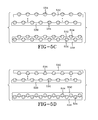
- Fig. 5 is a side view of a cross feed extruder system having a die as shown in Fig. 5A for forming ply as shown in Figs. 5B, 5C and 5D.
- Fig. 6 is a side view of a second embodiment of a calender system for forming ply;
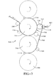
- Fig. 7 is a side view of a second embodiment of a calender system for forming ply;
- Figs. 8-10 are front views of alternate dies for use in the calender systems of the inventions.
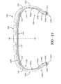
- Fig. 11 is a cross-sectional view of a tire assembly.
- Any or all of the ply layers in a tire may comprise one or more layers of a reduced gauge ply having a reduced thickness on the order of 30% to 100 %, preferably 40% to 75%, of the gauge thickness of a standard layer of ply. The ply configurations as described herein may be used in tire configurations such as, for example, passenger tires, truck tires, aircraft tires or off the road tires.
- A standard layer of ply is defined herein as having a depth or gauge in the range of 0.03 to 0.06 inches, typically 0.045 inches. A standard layer of ply typically has a cord spacing in the range of 18 to 36 epi, generally 28 epi, and with cord diameters in the range of 0.02 to 0.04 inches. The ply layers in a tire may have different thicknesses. Alternatively, one or more of the ply layers may have a reduced cord spacing on the order of 30% to 100%, preferably 40% to 75%, of the epi spacing of a standard layer of ply. Alternatively, any or all of the ply layers in a tire may comprise a reduced gauge ply having a reduced thickness on the order of 30% to 100 %, preferably 40% to 75%, of the normal gauge thickness and a reduced cord spacing on the order of 30% to 100%, preferably 40% to 75%, of the epi spacing.
- One example of a ply layer construction is shown in Figures 1 a and 1 b. The first layer and second layer of
ply 10 may each have a gauge thickness in the range of 30% to 100% of standard ply gauge, and a cord spacing in the range of 30% to 100% the standard cord spacing. In one example,ply layers 10 may each comprise a gauge thickness of 50% standard thickness and a reduced cord spacing of 50% of the standard cord spacing. Whenlayers 10 are combined together, the total thickness of both layers is 100% of the standard thickness and a combined epi cord spacing of 100% of the standard epi. However,ply layers 10 may each have different gauge thickness and cord spacing and when layered together, the combined total thickness may result in a nonstandard thickness and cord spacing. - As shown in Figure 1 B, the cords of
ply layers 10 may be oriented at the top edge of the ply so that thecord 12 is flush with thegum layer 14. The cords of the first layer ofply 10 may be offset from the cords of the second layer of ply as shown in Figure 2B. For example, when the two layers of ply are assembled together, they may have the thickness and cord spacing of a typical layer of ply. In one example, the thickness of the ply layers is 0.036 inches and the cord diameters are 0.026 inches in diameter. The cord spacing of each layer is 14 epi. When layered together as in Figure 1 B, the full gauge thickness of the combined layers is 0.072 inches and 28 epi. The cords are staggered. - Alternatively as shown in Figures 2A and 2B,
ply layers 20 have thecords 22 impregnated about half way into thegum surface 24 of the ply. Thelayers 20 may be stacked on top of each other so that the gum orback edge 26 of the first ply layer mates with theupper surface 28 of the second ply layer as shown in Figure 2B. For example, if 0.026 inch diameter cords are used in a 0.023 inch thick gum base, this results in a 0.10 inch thickness "t" between the lower end of the cord to the end of the ply. In one example, the thickness of theply layers 20 are 0.023 inches and the cord diameters are 0.026 inches in diameter. The cord spacing of each layer is 14 epi. When layered together as in Figure 2B, the full gauge thickness of the combined layers is 0.042 inches and 28 epi. The cords are preferably staggered when the ply layers are assembled together. - Alternatively as shown in Figures 3A-3D,
ply layers 30 have thecords 32 impregnated about half way into thegum surface 34 of the ply, with askim coat 36 of rubber layered over the cords. Thelayers 30 may be stacked on top of each other so that the gum or back edge of the first ply layer mates with the upper surface of the second ply layer as shown in Figure 3D. Ply layers 30 may be assembled such that the cords are abutted face to face wherein the cords of the upper layer are located between the cords of the lower layer, as shown in Figure 3B,C. Theskim coat 36 forms a protective barrier over thecords 32. The skim coat may comprise a thin layer of gum rubber, having a thickness typically in the range of 0.003 to 0.007 inches. Preferably the cords are encapsulated between the gum rubber and the skim coat layer. - The ply layers as described above may be formed from a
calender system 400 as shown in Figure 4. Rubber is fed to the nip offirst calender roll 402 and asecond calender roll 404 to form thebase gum layer 406 of the ply.Trim knife 408 is used to trim off excess rubber to form the desired width of thebase gum layer 406. Pull offroller 410 guides thebase gum layer 406 and maintains the appropriate tension. Thebase gum layer 406 is fed toassembly roller 412 having a die 414 located in mating contact with thebase gum layer 406. A plurality ofcords 415 are fed through the die inlet into engagement with the base gum layer mounted over theassembly roller 412. Thedie 410 maintains the desired cord spacing. Examples of dies which may be used with thesystem 400 are shown in Figures 8-10, and are described in more detail inUS application no. 11/240,430 filed on September 30, 2005 - The cords upon exiting the die, are pressed into the top layer of the base ply by the pressure of the die against the
assembly roller 412. An optional skim coat ofrubber 422 may be applied as a top layer over the cords. Rubber is fed between tworollers skim coat 422 is applied over the cord/gum layer whereinstitcher roller 414 stitches the skim layer onto the cord/gum layer.Trim knife 424 trims the formed ply to the desired width. - The ply layers shown in Figures 1-3 may also be formed from a
cross-feed extruder system 500 shown in Figure 5. As shown in Figure 5a, a cross-feed extruder die 510 may be used havinggrooves 514 in theupper plate 512 of the die for receiving the cords therein. The grooves are spaced to match the desired cord epi spacing. The cords are pulled through thegrooves 514 in the cross feed extruder die by pull-uproller 520. The angle α of the pull uproller 520 is adjustable to pull cords more or less tightly againstgrooves 514 in die. The higher the angle, the more tightly the cords lie against grooved 514. The angle α may be, for example, in the range of 20-60 degrees. As the cords are pulled through the cross feed extruder, they are coated with rubber. The resultingply 530 formed by the cross-head extruder has abase gum layer 532 withcords 534 impregnated into the base layer. A thin layer of rubber coats the cords. The ply layers 530 may be assembled top to bottom as shown in Figure 5c or wherein one of the ply layers is flipped over so that the cords are face to face as shown in Fig. 5d. - A second embodiment of a calendering system is shown in Figure 6. Rubber is fed to the nip of a
first calender roll 602 andsecond calender roll 604 to form thebase gum layer 600 of the ply.Trim knife 608 is used to trim off excess rubber to form the desired width of thebase gum layer 600. For example, the base gum layer may be trimmed to a strip of 3.7 inches wide, with a thickness of 0.03 inches. - A bank of rubber is fed into nip of
calender rollers thin skim coat 630 of rubber, which for example, may have a gauge of 0.003 to 0.005 inches. A plurality of cords are pressed into theskim coat 630 via adie 410 as described above, located in mating contact with theskim coat layer 630. Thedie 410 is mounted adjacent theassembly roller 612 so that the cords are in mating engagement with theskim coat 630. A plurality of cords are fed through the die inlet into engagement with the skimcoat gum layer 630 mounted over theassembly roller 612. The die maintains the desired cord spacing. The cords are pressed into the top layer of the base ply by the pressure of the die against theassembly roller 612. The cords may be stitched into the skim coat bycord stitcher roller 632. Thebase gum layer 600 is fed to the nip ofassembly roller 612 for mating engagement with a skim coat cord impregnatedlayer 650 formingply layer 655. An optionalsecondary stitcher 660 may be used to eliminate any remaining trapped air.Trim knife 670 trims theply layer 655 to the desired width before being pulled off the calender system byrollers 680. - A third embodiment of a
calender system 700 is shown in Figure 7. Rubber is fed by an extruder or other means for processing rubber (not shown) to the nip offirst calender roll 702 and asecond calender roll 704 to form thebase gum layer 706 of the ply.Trim knife 708 is used to trim off excess rubber to form the desired width of thebase gum layer 706. For example, the base gum layer may be trimmed to a strip of 3.7 inches wide, with a thickness of 0.03 inches. Base gum layer is then fed toassembly roller 710. Cords fed intodie 410 are pressed into the base gum layer onassembly roller 710. The cord impregnatedbase gum layer 702 is fed to the nip of assembly roller 712 androller 714 for mating engagement with askim coat layer 716, wherein the assembled components form aply layer 720. An optionalsecondary stitcher 760 may be used to eliminate any remaining trapped air.Trim knife 770 trims theply layer 720 to the desired width before being pulled off the calender system byrollers 780. - A cross-sectional view of a
tire assembly 200 is shown in Figure 11.Ply layer 210 is located radially outward of theinner liner 112, and has afirst end 212 locatedadjacent bead 114b. Theply layer 210 extends up from thefirst end 212, up thesidewall 104b, under thetread 102, down theother sidewall 104a and extends down to theother bead 114a. The ends 212, 214 ofply layer 210 do not wrap around either bead. A second layer ofsidewall ply ply 210 in the sidewall and shoulder area. Afirst sidewall ply 220a has afirst end 222 located under theinner tread belt 108 and extends down thesidewall 104a, wraps around thebead 114a and apex 116a, and has a turned upend 224 located on the interior of the tire assembly. Asecond sidewall ply 220b has afirst end 226 located under theinner tread belt 108 and extends down thesidewall 104b, wraps around thebead 114b and apex 116b, and has a turned upend 228 located on the interior of the tire assembly. Thus the second layer of ply 220 does not extend under the crown portion of the tire. Each of the ply layers 210, 220 has a reduced thickness of 0.026 inches and a reduced cord spacing of 18 epi. When assembled together, the total gauge thickness is 0.052 inches with a cord spacing of 36 epi. Any of the ply configurations described in the preceding paragraphs would work with the tire configuration.
Claims (8)
- A method of making ply, the method comprising the steps of:calendering a base coat (34) of rubber between a first and second calender rollers (402, 404);calendering a skim layer (36) of rubber between an assembly roller (412) and a fourth calender roller (418);pressing a plurality of cords (32) onto the skim layer (36) of rubber forming a cord layer (30);and mating the base coat (34) of rubber with the cord layer (30) to form a layer of ply.
- A method of making ply comprising: extruding a plurality of cords through a cross-head extruder, wherein the cords are aligned in a die, and forming a base layer of rubber wherein the cords are impregnated within the base layer.
- The method of claim 1 or 2, wherein the cords are not flush with the surface of the base layer.
- A layer of ply comprising a layer of gum rubber and a plurality of cords partially embedded within the layer of rubber.
- The layer of ply of claim 4, wherein the cord spacing is in the range of 9 to 18 epi or in the range of 18 to 36 epi.
- The layer of ply of claim 4 or 5, wherein the gauge thickness of the ply is in the range of 0.5 mm to 1.5 mm, alternately in the range from 0.5 mm to 1.14 mm.
- The layer of ply of at least one of the claims 4-6, wherein the cords are tangent to the upper surface of the rubber layer.
- A layer of ply comprising a layer of rubber and a plurality of cords, wherein the cord spacing is in the range of 9 to 18 epi, and wherein the gauge thickness of the layer of ply is in the range of 0.5 mm to 1.5 mm.
Applications Claiming Priority (1)
| Application Number | Priority Date | Filing Date | Title |
|---|---|---|---|
| US11/290,689 US20070122605A1 (en) | 2005-11-30 | 2005-11-30 | Apparatus and method of manufacturing reduced gauge tire ply |
Publications (2)
| Publication Number | Publication Date |
|---|---|
| EP1792719A2 true EP1792719A2 (en) | 2007-06-06 |
| EP1792719A3 EP1792719A3 (en) | 2007-08-15 |
Family
ID=37813529
Family Applications (1)
| Application Number | Title | Priority Date | Filing Date |
|---|---|---|---|
| EP20060124733 Withdrawn EP1792719A3 (en) | 2005-11-30 | 2006-11-24 | Apparatus and method of manufacturing reduced gauge tire ply |
Country Status (5)
| Country | Link |
|---|---|
| US (1) | US20070122605A1 (en) |
| EP (1) | EP1792719A3 (en) |
| JP (1) | JP2007152948A (en) |
| CN (1) | CN100594118C (en) |
| BR (1) | BRPI0604828A (en) |
Cited By (2)
| Publication number | Priority date | Publication date | Assignee | Title |
|---|---|---|---|---|
| FR2922143A1 (en) * | 2007-10-11 | 2009-04-17 | Michelin Soc Tech | Gum band manufacturing system for manufacturing tire, has extrusion device with opening for extruding gum band, and wire displacing unit with band displacing unit arranged in downstream of opening to displace band in downstream of opening |
| WO2019123200A1 (en) * | 2017-12-20 | 2019-06-27 | Bridgestone Europe Nv/Sa | Method for the production of a fabric for the manufacture of a ply of a pneumatic tyre and method for the construction of said pneumatic tyre |
Families Citing this family (12)
| Publication number | Priority date | Publication date | Assignee | Title |
|---|---|---|---|---|
| TR201104076A1 (en) * | 2011-04-26 | 2012-11-21 | Kordsa Global End�Str�Yel �Pl�K Ve Kord Bez� San. Ve T�C. A.�. | Production method of the tire belt upper belt. |
| WO2014021830A1 (en) * | 2012-07-31 | 2014-02-06 | Compagnie Generale Des Etablissements Michelin | Automatic startup and continued operation of calendering drives for elastomeric mixes |
| JP5756451B2 (en) * | 2012-12-11 | 2015-07-29 | 住友ゴム工業株式会社 | Pneumatic tire |
| CN104476778B (en) * | 2014-12-01 | 2017-02-22 | 浙江大学台州研究院 | Manufacturing device of wire cord fabric for rubber track and manufacturing method |
| JP6152867B2 (en) * | 2015-04-06 | 2017-06-28 | 横浜ゴム株式会社 | Method and apparatus for manufacturing rubber extruded member |
| NL2016826B1 (en) * | 2016-05-25 | 2017-12-12 | Vmi Holland Bv | Extruder head for extruding cord-reinforced extrudate |
| US11806910B2 (en) * | 2017-10-16 | 2023-11-07 | Compagnie Generale Des Etablissements Michelin | Production of a layered semi-finished product for use in tire production |
| EP3763507A4 (en) * | 2018-04-09 | 2021-12-08 | Sumitomo Rubber Industries, Ltd. | Rubber-coated cord manufacturing device and rubber-coated cord manufacturing method |
| FR3099890A1 (en) * | 2019-08-12 | 2021-02-19 | Compagnie Generale Des Etablissements Michelin | Wire Guiding and Holding Machine and Method of Use |
| CN119682097A (en) | 2019-08-12 | 2025-03-25 | 米其林集团总公司 | Filament guide holding machine and method of use |
| US20210387395A1 (en) * | 2020-06-10 | 2021-12-16 | The Goodyear Tire & Rubber Company | Die for a polymer mixing machine and tire ply produced by same |
| CN119773322A (en) * | 2025-01-15 | 2025-04-08 | 芜湖风雪橡胶有限公司 | Multilayer composite rubber and manufacturing method thereof |
Family Cites Families (27)
| Publication number | Priority date | Publication date | Assignee | Title |
|---|---|---|---|---|
| GB191105036A (en) * | 1911-02-28 | 1912-02-28 | Mann Trikotweberei Ag | Improvements in and relating to the Manufacture of Rubber Goods. |
| US1509301A (en) * | 1924-01-22 | 1924-09-23 | New England Tire & Rubber Comp | Nonskid tire |
| GB580838A (en) * | 1944-08-15 | 1946-09-20 | Us Rubber Co | Improvements in method of making pneumatic tyres |
| US2650642A (en) * | 1950-08-24 | 1953-09-01 | Us Rubber Co | Method of preventing blows in manufacture of pneumatic tires |
| GB681872A (en) * | 1950-11-21 | 1952-10-29 | Continental Gummi Werke Ag | Improvements in or relating to reinforced rubber objects |
| US2754883A (en) * | 1952-12-22 | 1956-07-17 | Firestone Tire & Rubber Co | Apparatus for tension-calendering fabric |
| GB868954A (en) * | 1957-03-08 | 1961-05-25 | Olympic Tyre & Rubber Company | Method and apparatus for processing cord |
| NL280535A (en) * | 1961-08-14 | |||
| USB372753I5 (en) * | 1965-04-30 | 1900-01-01 | ||
| FR2134244B1 (en) * | 1971-04-28 | 1973-12-28 | Michelin & Cie | |
| US3904457A (en) * | 1972-06-07 | 1975-09-09 | Firestone Tire & Rubber Co | Method of ultrasonic butt splicing reinforced tire fabric |
| US3843434A (en) * | 1972-06-12 | 1974-10-22 | Industrial Nucleonics Corp | Process control |
| US4399854A (en) * | 1981-06-15 | 1983-08-23 | Dirocco Jobbie | Tire repair patch and method of manufacture |
| US4435477A (en) * | 1983-07-25 | 1984-03-06 | The Firestone Tire & Rubber Company | Rubber compositions and articles thereof having improved metal adhesion and metal adhesion retention |
| GB8726630D0 (en) * | 1987-11-13 | 1987-12-16 | Holroyd Associates Ltd | Reinforced polymeric article |
| JP2951699B2 (en) * | 1990-07-18 | 1999-09-20 | 株式会社ブリヂストン | Method and apparatus for forming corded rubber sheet |
| JPH0531829A (en) * | 1991-07-26 | 1993-02-09 | Bridgestone Corp | Ply manufacturing method, tire ply for carcass, and tire |
| JP3402395B2 (en) * | 1994-02-28 | 2003-05-06 | 株式会社ブリヂストン | Steel cord alignment device and method for manufacturing radial tire treat using the same |
| US5662751A (en) * | 1994-09-20 | 1997-09-02 | Michelin Recherche Et Technique S.A. | Tire with a specified two-ply steel-aramid belt package |
| US6280548B1 (en) * | 1995-01-05 | 2001-08-28 | Goodyear Tire & Rubber | Method and apparatus for building a laminate and forming a carcass subassembly for a tire |
| US6748731B2 (en) * | 2002-04-08 | 2004-06-15 | Tokusen U.S.A., Inc. | Tire cord |
| DE10258353B4 (en) * | 2002-12-12 | 2007-07-26 | Berstorff Gmbh | Calendering plant for the production of steel cable car tracks |
| JP4348109B2 (en) * | 2003-04-30 | 2009-10-21 | 住友ゴム工業株式会社 | Tire cord topping method and topping device |
| US7524398B2 (en) * | 2004-12-23 | 2009-04-28 | The Goodyear Tire & Rubber Company | Apparatus for making tire components, and a tire |
| US20060137804A1 (en) * | 2004-12-23 | 2006-06-29 | Downing Daniel R | Method for making tire ply |
| US20060137814A1 (en) * | 2004-12-23 | 2006-06-29 | Downing Daniel R | Method for making reinforced elastomeric materials |
| US7509987B2 (en) * | 2005-11-22 | 2009-03-31 | The Goodyear Tire & Rubber Company | Tire with turned down ply construction |
-
2005
- 2005-11-30 US US11/290,689 patent/US20070122605A1/en not_active Abandoned
-
2006
- 2006-11-22 BR BRPI0604828-5A patent/BRPI0604828A/en not_active IP Right Cessation
- 2006-11-24 EP EP20060124733 patent/EP1792719A3/en not_active Withdrawn
- 2006-11-30 JP JP2006324429A patent/JP2007152948A/en active Pending
- 2006-11-30 CN CN200610163679A patent/CN100594118C/en not_active Expired - Fee Related
Cited By (2)
| Publication number | Priority date | Publication date | Assignee | Title |
|---|---|---|---|---|
| FR2922143A1 (en) * | 2007-10-11 | 2009-04-17 | Michelin Soc Tech | Gum band manufacturing system for manufacturing tire, has extrusion device with opening for extruding gum band, and wire displacing unit with band displacing unit arranged in downstream of opening to displace band in downstream of opening |
| WO2019123200A1 (en) * | 2017-12-20 | 2019-06-27 | Bridgestone Europe Nv/Sa | Method for the production of a fabric for the manufacture of a ply of a pneumatic tyre and method for the construction of said pneumatic tyre |
Also Published As
| Publication number | Publication date |
|---|---|
| BRPI0604828A (en) | 2007-10-09 |
| JP2007152948A (en) | 2007-06-21 |
| CN101007442A (en) | 2007-08-01 |
| EP1792719A3 (en) | 2007-08-15 |
| CN100594118C (en) | 2010-03-17 |
| US20070122605A1 (en) | 2007-05-31 |
Similar Documents
| Publication | Publication Date | Title |
|---|---|---|
| US20070122605A1 (en) | Apparatus and method of manufacturing reduced gauge tire ply | |
| EP1674246A1 (en) | Method for making tire ply | |
| US20010050134A1 (en) | Method of producing pneumatic tires | |
| US7524398B2 (en) | Apparatus for making tire components, and a tire | |
| US20070031529A1 (en) | Apparatus for forming elastomeric tire component and a tire | |
| JP2002187408A (en) | Composite reinforced rubber material, method for producing the same, and pneumatic tire | |
| US20100024960A1 (en) | Body ply and insert assembly method | |
| EP1516752A1 (en) | Tire bead configuration | |
| US20150107746A1 (en) | Tire apex structure | |
| US7971615B2 (en) | Tire with turned down ply construction | |
| US7509987B2 (en) | Tire with turned down ply construction | |
| JP3683065B2 (en) | Pneumatic radial tire | |
| EP3173222B1 (en) | Method of manufacturing a tire with a monolayer belt component | |
| US7780809B2 (en) | Method for forming elastomeric tire component and a tire | |
| JP2008213750A (en) | Pneumatic tire and manufacturing method for pneumatic tire | |
| EP0928705B1 (en) | Pneumatic radial tire | |
| US7670449B2 (en) | Method of manufacturing tire with turned down ply construction | |
| US6645334B1 (en) | Tire manufacturing using a roll forming apparatus | |
| CN112313088A (en) | Pneumatic tires | |
| EP1674247A1 (en) | Method for making reinforced elastomeric materials | |
| US20070122582A1 (en) | Method and apparatus for producing a monocomposite for a tire component | |
| US12109773B2 (en) | Method and apparatus for forming an apex | |
| EP1787827A1 (en) | A tire with turned down ply contruction and a method to manufacture such a tire | |
| JPH0531829A (en) | Ply manufacturing method, tire ply for carcass, and tire | |
| US20120148702A1 (en) | Extruder die assembly |
Legal Events
| Date | Code | Title | Description |
|---|---|---|---|
| PUAI | Public reference made under article 153(3) epc to a published international application that has entered the european phase |
Free format text: ORIGINAL CODE: 0009012 |
|
| AK | Designated contracting states |
Kind code of ref document: A2 Designated state(s): AT BE BG CH CY CZ DE DK EE ES FI FR GB GR HU IE IS IT LI LT LU LV MC NL PL PT RO SE SI SK TR |
|
| AX | Request for extension of the european patent |
Extension state: AL BA HR MK YU |
|
| PUAL | Search report despatched |
Free format text: ORIGINAL CODE: 0009013 |
|
| AK | Designated contracting states |
Kind code of ref document: A3 Designated state(s): AT BE BG CH CY CZ DE DK EE ES FI FR GB GR HU IE IS IT LI LT LU LV MC NL PL PT RO SE SI SK TR |
|
| AX | Request for extension of the european patent |
Extension state: AL BA HR MK YU |
|
| 17P | Request for examination filed |
Effective date: 20080215 |
|
| AKX | Designation fees paid |
Designated state(s): DE FR GB IT |
|
| 17Q | First examination report despatched |
Effective date: 20080410 |
|
| STAA | Information on the status of an ep patent application or granted ep patent |
Free format text: STATUS: THE APPLICATION IS DEEMED TO BE WITHDRAWN |
|
| 18D | Application deemed to be withdrawn |
Effective date: 20090917 |